EP2487085A2 - Lane departure warning system and a method for a lane departure warning system - Google Patents
Lane departure warning system and a method for a lane departure warning system Download PDFInfo
- Publication number
- EP2487085A2 EP2487085A2 EP12154658A EP12154658A EP2487085A2 EP 2487085 A2 EP2487085 A2 EP 2487085A2 EP 12154658 A EP12154658 A EP 12154658A EP 12154658 A EP12154658 A EP 12154658A EP 2487085 A2 EP2487085 A2 EP 2487085A2
- Authority
- EP
- European Patent Office
- Prior art keywords
- vehicle
- deviation
- lane
- signal
- alarm
- Prior art date
- Legal status (The legal status is an assumption and is not a legal conclusion. Google has not performed a legal analysis and makes no representation as to the accuracy of the status listed.)
- Withdrawn
Links
Images

Classifications
-
- B—PERFORMING OPERATIONS; TRANSPORTING
- B60—VEHICLES IN GENERAL
- B60W—CONJOINT CONTROL OF VEHICLE SUB-UNITS OF DIFFERENT TYPE OR DIFFERENT FUNCTION; CONTROL SYSTEMS SPECIALLY ADAPTED FOR HYBRID VEHICLES; ROAD VEHICLE DRIVE CONTROL SYSTEMS FOR PURPOSES NOT RELATED TO THE CONTROL OF A PARTICULAR SUB-UNIT
- B60W30/00—Purposes of road vehicle drive control systems not related to the control of a particular sub-unit, e.g. of systems using conjoint control of vehicle sub-units
- B60W30/10—Path keeping
- B60W30/12—Lane keeping
-
- B—PERFORMING OPERATIONS; TRANSPORTING
- B60—VEHICLES IN GENERAL
- B60W—CONJOINT CONTROL OF VEHICLE SUB-UNITS OF DIFFERENT TYPE OR DIFFERENT FUNCTION; CONTROL SYSTEMS SPECIALLY ADAPTED FOR HYBRID VEHICLES; ROAD VEHICLE DRIVE CONTROL SYSTEMS FOR PURPOSES NOT RELATED TO THE CONTROL OF A PARTICULAR SUB-UNIT
- B60W50/00—Details of control systems for road vehicle drive control not related to the control of a particular sub-unit, e.g. process diagnostic or vehicle driver interfaces
- B60W50/08—Interaction between the driver and the control system
- B60W50/14—Means for informing the driver, warning the driver or prompting a driver intervention
-
- B—PERFORMING OPERATIONS; TRANSPORTING
- B62—LAND VEHICLES FOR TRAVELLING OTHERWISE THAN ON RAILS
- B62D—MOTOR VEHICLES; TRAILERS
- B62D15/00—Steering not otherwise provided for
- B62D15/02—Steering position indicators ; Steering position determination; Steering aids
- B62D15/029—Steering assistants using warnings or proposing actions to the driver without influencing the steering system
-
- H—ELECTRICITY
- H04—ELECTRIC COMMUNICATION TECHNIQUE
- H04S—STEREOPHONIC SYSTEMS
- H04S3/00—Systems employing more than two channels, e.g. quadraphonic
- H04S3/002—Non-adaptive circuits, e.g. manually adjustable or static, for enhancing the sound image or the spatial distribution
-
- B—PERFORMING OPERATIONS; TRANSPORTING
- B60—VEHICLES IN GENERAL
- B60W—CONJOINT CONTROL OF VEHICLE SUB-UNITS OF DIFFERENT TYPE OR DIFFERENT FUNCTION; CONTROL SYSTEMS SPECIALLY ADAPTED FOR HYBRID VEHICLES; ROAD VEHICLE DRIVE CONTROL SYSTEMS FOR PURPOSES NOT RELATED TO THE CONTROL OF A PARTICULAR SUB-UNIT
- B60W2552/00—Input parameters relating to infrastructure
- B60W2552/53—Road markings, e.g. lane marker or crosswalk
-
- H—ELECTRICITY
- H04—ELECTRIC COMMUNICATION TECHNIQUE
- H04R—LOUDSPEAKERS, MICROPHONES, GRAMOPHONE PICK-UPS OR LIKE ACOUSTIC ELECTROMECHANICAL TRANSDUCERS; ELECTRIC HEARING AIDS; PUBLIC ADDRESS SYSTEMS
- H04R2499/00—Aspects covered by H04R or H04S not otherwise provided for in their subgroups
- H04R2499/10—General applications
- H04R2499/13—Acoustic transducers and sound field adaptation in vehicles
-
- H—ELECTRICITY
- H04—ELECTRIC COMMUNICATION TECHNIQUE
- H04R—LOUDSPEAKERS, MICROPHONES, GRAMOPHONE PICK-UPS OR LIKE ACOUSTIC ELECTROMECHANICAL TRANSDUCERS; ELECTRIC HEARING AIDS; PUBLIC ADDRESS SYSTEMS
- H04R3/00—Circuits for transducers
- H04R3/12—Circuits for transducers for distributing signals to two or more loudspeakers
-
- H—ELECTRICITY
- H04—ELECTRIC COMMUNICATION TECHNIQUE
- H04S—STEREOPHONIC SYSTEMS
- H04S7/00—Indicating arrangements; Control arrangements, e.g. balance control
- H04S7/30—Control circuits for electronic adaptation of the sound field
Definitions
- the present invention relates to a lane departure warning system, and a method for a lane departure warning system, for vehicles, according to the preambles of the independent claims. More specifically the invention relates to a system and a method for warning the driver of a vehicle, e.g. a truck, bus or car, if the vehicle is unintendedly about to leave its traffic lane.
- a vehicle e.g. a truck, bus or car
- a vehicle's unintended deviation from its traffic lane is one of the main causes of traffic accidents. There are many reasons for such unintended deviation, e.g. handling of and conversation via mobile telephones, inattention when setting the radio, falling asleep while driving.
- LDW lane departure warning
- a conventional LDW system described for example in EP 1074430 is configured to monitor the vehicle's position on the road relative to the lane markings. Such systems often have a camera for saving the visible lane markings and an image processor for determining the vehicle's position relative to its lane. When the vehicle crosses or is about to cross the lane marking, the system generates automatically a warning to the driver.
- US 2009/0021358 refers to an LDW system adapted to delivering first and second warning signals based on deviation from a traffic lane.
- the first warning signal is generated when the vehicle's wheels approach the lane markings, and may be regarded as a pre-warning.
- the second warning signal is generated when the vehicle's wheels pass the lane markings.
- the first warning signal may take the form of vibration in the steering wheel and the second warning signal the form of a lamp signal.
- US 20100295707 A1 also relates to an LDW system which is adapted to generating warning signals, e.g. lamp, acoustic and/or haptic signals, with different intensities depending inter alia on the degree of activeness exhibited by the driver.
- warning signals e.g. lamp, acoustic and/or haptic signals
- EP 1663711 A1 also refers to an LDW system intended inter alia to reduce the number of false or unnecessary alarms. This system also monitors the driver's activeness by measuring a number of parameters relating to how he/she is driving the vehicle, e.g. in terms of steering activity, pedal use and acceleration changes. If these parameters indicate that the driver is actively driving the vehicle, the LDW system need not generate any warning signals.
- the object of the present invention is to propose an improved lane departure warning system which helps to reduce the number of alarms generated when the vehicle is on the point of leaving its traffic lane but which at the same time results in improved safety.
- the present invention is based on the inventors' understanding and knowledge of research into the ability of human beings to perceive changes in their environment, and in particular their ability to perceive changes of where an acoustic signal is coming from. Applying this knowledge to generate warning signals in conjunction with LDW systems results in a system which is highly acceptable to users.
- the present invention uses the fact that human beings react to significant changes in the sonic environment. These may be acoustic changes, e.g. a rising sound level. They may also be semantic changes, e.g. one's name being heard.
- the intention of the present invention is to use changes in directions of sounds to attract driver attention. Research has shown that sounds generated in a direction in a vehicle can draw the driver's attention to the specific direction, see for example the article entitled "Assessing the Effectiveness of Various Auditory Cues in Capturing a Driver's Visual Attention" by Cristy Ho and Charles Spence, published in Journal of Experimental Psychology: Applied, 2005, vol. 11, No. 3, pages 157-174 (http://www.apa.org/pubs/journals/features/xap-11-3-157.pdf ).
- a conventional warning system e.g. of the kind described above, often uses specifically intended warning signals to attract attention.
- the intention of the present invention is primarily to use existing sound from the vehicle's radio installation.
- an acoustic change takes place whereby sound is focused to one direction in the vehicle. This change in direction may potentially draw the driver's attention to that direction without any other warning signal having to be generated. Panning of music to indicate directions has been tested in aviation with promising results.
- the present invention is based on utilising information which comes from the LDW system in the form of the vehicle's position and bearing relative to its traffic lane and on providing a "gentler" and more acceptable indication that a warning is on the way before the actual legally required warning comes.
- the idea is also based on utilising existing signals but altering them to provide the driver with a gentle indication that the vehicle will shortly be leaving its traffic lane.
- using existing signals entails altering the "balance" of the sound which comes from the radio, e.g. moving all of the sound to the right side of the cab to indicate an imminent deviation to the right.
- the sound balance may depend on the distance or time to crossing the line.
- the indication has also to be such that if the driver counteracts the deviation, i.e. steers back into the traffic lane, the indication disappears.
- the solution according to the present invention differs from other solutions in that the driver is helped to keep the vehicle more in the middle of its lane without being appreciably disturbed, while at the same time the LDW system is adapted to responding to the vehicle leaving the lane by delivering an alarm signal strong enough to, for example, wake a driver who has fallen asleep.
- the LDW system according to the invention is more intuitive for the driver in that the indication which alters the alarm signal disappears when he/she counteracts the deviation.
- the system utilises sounds/vibrations/lamps which are "naturally" present but are altered in a way which is noticeable without being disturbing, and the present invention is relatively easy to implement since it involves no further hardware.
- a lane departure warning system according to a first embodiment of the present invention will now be described with reference to Figure 1 .
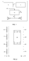
- Figure 1 depicts an LDW system 2 for a vehicle 20 (see Figure 2 ), comprising a lane monitoring unit 4 adapted to delivering a location signal 6 which indicates the vehicle's position relative to the lane markings 22 (see Figure 2 ) of a road.
- the system further comprises a lane deviation unit 8 adapted to calculating on the basis of said location signal 6 the vehicle's current deviation and prospective deviations from its lane, and the direction of deviation relative to the vehicle, and to generating on the basis thereof one or more deviation signals 10.
- the system also comprises an alarm unit 12 adapted to generating on the basis of said deviation signals 10 one or more alarm signals 14,16 to the vehicle's driver, comprising a first alarm signal 14 arranged to be generated if the vehicle's current deviation exceeds a first threshold value (T1,T1') which represents an impermissible deviation, and a second alarm signal 16 arranged to be generated if said deviation signal 10 indicates that the vehicle will impermissibly deviate from its lane.
- Said second alarm signal 16 is an acoustic signal which indicates the direction of prospective deviation relative to the vehicle.
- the second alarm signal 16 may for example be implemented in the form of a change in the existing acoustic environment in the driver's cab, e.g. by the radio programme or other material already coming through the loudspeakers being altered so that its sound balance changes. If a first alarm signal has thereafter to be generated, the radio programme is interrupted and the signal is generated to warn the driver.
- the lane monitoring unit is configured, according to a preferred embodiment, as an image processing system comprising one or more cameras and an image processor, which do not appear in the diagrams.
- the camera or cameras are for example fitted at the windscreen, to the control panel or on top of the vehicle to save visible lane markings on the road.
- the image information generated by the camera is fed to the image processor, which delivers to the deviation unit a location signal which indicates the vehicle's position relative to the lane markings.
- the alarm unit is adapted to generating optical, acoustic and/or haptic signals to warn the driver.
- the diagram shows two loudspeakers for delivering the second alarm signal in the form of acoustic signals.
- the first alarm signal may also be delivered in the form of an acoustic signal alone or in combination with optical and/or haptic signals.
- the second alarm signal may be delivered in combination with optical and/or haptic signals.
- FIG. 2 depicts a vehicle 20 in a traffic lane with lane markings 22. Calculating the vehicle's location is preferably based on calculating the position of its wheels 24 relative to the lane markings 22.
- the centrelines of the lane markings on the respective right and left sides of the vehicle are marked L and L'.
- Respective first threshold values T1 and T1' indicate the distance from the lane markings at which the LDW system has to generate a first alarm signal. This threshold value according to a preferred embodiment is 0.3 metre beyond the markings.
- Respective second threshold values T2 and T2' are also depicted.
- the system is adapted to generating the second alarm signal.
- the second threshold value may for example be 0.1 metre within the markings.
- the second threshold value may be zero so that the second alarm signal is generated when a wheel of the vehicle is on the lane markings.
- the second threshold value may have a significantly larger value, e.g. of the order of 0.5 metre, and for there to be one or more further threshold values between the second threshold value and the lane markings. This makes it possible to provide a second alarm signal which varies with the distance between the position of the vehicle wheel and the lane markings.
- the direction of prospective deviation is indicated by altering the balance of the vehicle's sound system.
- the change in the sound balance takes place at a stage where the prospective deviation is less than the second threshold value or where the vehicle's position relative to the lane markings indicates a prospective deviation.
- the second alarm signal is designated 16 and the first alarm signal 14.
- the first alarm signal has a higher amplitude (A) than the second alarm signal. This may for example mean that the first alarm signal is delivered at a higher intensity (louder sound) than the second alarm signal.
- the change in the sound balance takes place continuously with changes in the vehicle's position relative to the lane markings.
- the second alarm signal is designated 16 and the first alarm signal 14.
- the first alarm signal has a higher amplitude (A) than the second alarm signal.
- the change in the sound balance takes place gradually as the vehicle approaches the lane markings.
- the second alarm signal is variable in such a way that its intensity depends on how near in time the vehicle is to leaving its lane, or on its distance to leaving the lane, so that the intensity of the second alarm signal increases continuously the nearer the vehicle is to leaving the lane.
- the alarm unit is adapted to generating the second alarm signal when the deviation signal indicates that a prospective deviation is below a predetermined second threshold value.
- the second threshold value represents a predetermined time before a deviation occurs, and according to another embodiment said second threshold value represents a predetermined distance between the vehicle and the lane markings.
- the alarm unit will stop generating the second alarm signal if the deviation signal indicates that the prospective deviation will not occur, e.g. that the vehicle has moved away from the lane markings.
- the second alarm signal is generated on the basis of the vehicle's position relative to the lane markings.
- the invention thus comprises a lane departure warning system 2' for a vehicle 20', comprising a main monitoring unit 4' adapted to delivering a location signal 6' which indicates the vehicle's position relative to the lane markings 22 of a road, a lane deviation unit 8' adapted to calculating on the basis of said location signal 6' the vehicle's current deviation and the direction of deviation relative to the vehicle, and to generating on the basis thereof one or more deviation signals 10'.
- the alarm unit is adapted to generating on the basis of said location signal a second alarm signal 16' which indicates the vehicle's position relative to the lane markings, in the form of an acoustic signal.
- the vehicle's position relative to the lane markings is preferably indicated by altering the balance of its sound system, which takes place continuously depending on the vehicle's position relative to the lane markings.
- the intensity of the second alarm signal may change depending on the vehicle's position relative to the lane markings.
- the present invention comprises also a method pertaining to a lane departure warning system for a vehicle.
- the method comprises
- the method further comprises:
- the direction of prospective deviation is preferably indicated by altering the balance of the vehicle's sound system.
- the change in the sound balance takes place at a stage where the prospective deviation is less than the second threshold value or where the vehicle's position relative to the lane markings indicates a prospective deviation.
- the change in the sound balance takes place continuously depending on the vehicle's position relative to the lane markings.
- the alarm unit is adapted to generating the second alarm signal when the deviation signal indicates that a prospective deviation is less than a predetermined second threshold value.
- the second threshold value may either represent a predetermined time before a deviation occurs or a predetermined distance between the vehicle and the lane markings.
- the second alarm signal is variable in such a way that its intensity depends on how near in time the vehicle is to leaving its lane, or on the vehicle's distance to leaving its lane, so that the intensity of the second alarm signal increases continuously the nearer the vehicle is to leaving the lane.
- the alarm unit will preferably stop generating said second alarm signal.
- the invention comprises also a method which implements the lane departure warning system according to the second embodiment.
- This method comprises the steps of
- the method further comprises
- the vehicle's position relative to the lane markings is indicated by altering the balance of the vehicle's sound system, which preferably takes place continuously depending on the vehicle's position relative to the lane markings.
- the present invention may be implemented in the form of software or in the form of one or more hardware items or in the form of a combination of software and hardware.
- the invention will then comprise a computer programme product with programme code for performing the various steps of the invention when the programme code is run on a computer.
Landscapes
- Engineering & Computer Science (AREA)
- Transportation (AREA)
- Mechanical Engineering (AREA)
- Automation & Control Theory (AREA)
- Chemical & Material Sciences (AREA)
- Combustion & Propulsion (AREA)
- Physics & Mathematics (AREA)
- Acoustics & Sound (AREA)
- Signal Processing (AREA)
- Human Computer Interaction (AREA)
- Traffic Control Systems (AREA)
Abstract
Description
- The present invention relates to a lane departure warning system, and a method for a lane departure warning system, for vehicles, according to the preambles of the independent claims. More specifically the invention relates to a system and a method for warning the driver of a vehicle, e.g. a truck, bus or car, if the vehicle is unintendedly about to leave its traffic lane.
- A vehicle's unintended deviation from its traffic lane is one of the main causes of traffic accidents. There are many reasons for such unintended deviation, e.g. handling of and conversation via mobile telephones, inattention when setting the radio, falling asleep while driving.
- In 2013 the European Union will introduce a requirement for heavy vehicles to be equipped with a so-called lane departure warning (LDW) system with specific requirements that the warning must be by sound or vibration and give an indication of the direction in which the vehicle is about to leave its traffic lane. There is also a specific requirement that the warning must reach the driver at the latest 0.3 m after the respective tyre has left the lane marking.
- A conventional LDW system described for example in
EP 1074430 is configured to monitor the vehicle's position on the road relative to the lane markings. Such systems often have a camera for saving the visible lane markings and an image processor for determining the vehicle's position relative to its lane. When the vehicle crosses or is about to cross the lane marking, the system generates automatically a warning to the driver. -
US 2009/0021358 refers to an LDW system adapted to delivering first and second warning signals based on deviation from a traffic lane. The first warning signal is generated when the vehicle's wheels approach the lane markings, and may be regarded as a pre-warning. The second warning signal is generated when the vehicle's wheels pass the lane markings. The first warning signal may take the form of vibration in the steering wheel and the second warning signal the form of a lamp signal. -
US 20100295707 A1 also relates to an LDW system which is adapted to generating warning signals, e.g. lamp, acoustic and/or haptic signals, with different intensities depending inter alia on the degree of activeness exhibited by the driver. -
EP 1663711 A1 also refers to an LDW system intended inter alia to reduce the number of false or unnecessary alarms. This system also monitors the driver's activeness by measuring a number of parameters relating to how he/she is driving the vehicle, e.g. in terms of steering activity, pedal use and acceleration changes. If these parameters indicate that the driver is actively driving the vehicle, the LDW system need not generate any warning signals. - One of the basic problems of today's LDW systems is the desirability of warning the driver sufficiently to wake him/her if he/she has fallen asleep, while at the same time making it possible, depending on the situation, for there to be, without any system errors, a very large number of warnings per 10 km travelled. It is therefore very important to provide a system which is highly acceptable to drivers.
- The object of the present invention is to propose an improved lane departure warning system which helps to reduce the number of alarms generated when the vehicle is on the point of leaving its traffic lane but which at the same time results in improved safety.
- The above objects are achieved with the invention defined by the independent claims.
- Preferred embodiments are defined by the dependent claims.
- The present invention is based on the inventors' understanding and knowledge of research into the ability of human beings to perceive changes in their environment, and in particular their ability to perceive changes of where an acoustic signal is coming from. Applying this knowledge to generate warning signals in conjunction with LDW systems results in a system which is highly acceptable to users.
- More specifically, the present invention uses the fact that human beings react to significant changes in the sonic environment. These may be acoustic changes, e.g. a rising sound level. They may also be semantic changes, e.g. one's name being heard. The intention of the present invention is to use changes in directions of sounds to attract driver attention. Research has shown that sounds generated in a direction in a vehicle can draw the driver's attention to the specific direction, see for example the article entitled "Assessing the Effectiveness of Various Auditory Cues in Capturing a Driver's Visual Attention" by Cristy Ho and Charles Spence, published in Journal of Experimental Psychology: Applied, 2005, vol. 11, No. 3, pages 157-174 (http://www.apa.org/pubs/journals/features/xap-11-3-157.pdf).
- A conventional warning system, e.g. of the kind described above, often uses specifically intended warning signals to attract attention. The intention of the present invention is primarily to use existing sound from the vehicle's radio installation. When the sound from the radio installation is panned in the driver environment, an acoustic change takes place whereby sound is focused to one direction in the vehicle. This change in direction may potentially draw the driver's attention to that direction without any other warning signal having to be generated. Panning of music to indicate directions has been tested in aviation with promising results.
- The present invention is based on utilising information which comes from the LDW system in the form of the vehicle's position and bearing relative to its traffic lane and on providing a "gentler" and more acceptable indication that a warning is on the way before the actual legally required warning comes.
- The idea is also based on utilising existing signals but altering them to provide the driver with a gentle indication that the vehicle will shortly be leaving its traffic lane.
- According to a preferred embodiment, using existing signals entails altering the "balance" of the sound which comes from the radio, e.g. moving all of the sound to the right side of the cab to indicate an imminent deviation to the right.
- Utilising existing signals may however also entail using the flasher sound at a different rate, indicating by the flasher symbol, vibrating a massage seat, putting vibration into the steering wheel or applying to the steering wheel a slight turning motion in the opposite direction.
- The sound balance may depend on the distance or time to crossing the line.
- The indication has also to be such that if the driver counteracts the deviation, i.e. steers back into the traffic lane, the indication disappears.
- The solution according to the present invention differs from other solutions in that the driver is helped to keep the vehicle more in the middle of its lane without being appreciably disturbed, while at the same time the LDW system is adapted to responding to the vehicle leaving the lane by delivering an alarm signal strong enough to, for example, wake a driver who has fallen asleep.
- The LDW system according to the invention is more intuitive for the driver in that the indication which alters the alarm signal disappears when he/she counteracts the deviation.
- The system utilises sounds/vibrations/lamps which are "naturally" present but are altered in a way which is noticeable without being disturbing, and the present invention is relatively easy to implement since it involves no further hardware.
-
-
Figure 1 is a schematic block diagram illustrating a first embodiment of the present invention. -
Figure 2 depicts a vehicle in a traffic lane with lane markings. -
Figure 3 is a flowchart illustrating the method according to the present invention. -
Figures 4 and 5 are graphs illustrating two embodiments of the present invention. -
Figure 6 is a schematic block diagram illustrating another embodiment of the present invention. - A lane departure warning system according to a first embodiment of the present invention will now be described with reference to
Figure 1 . -
Figure 1 depicts anLDW system 2 for a vehicle 20 (seeFigure 2 ), comprising alane monitoring unit 4 adapted to delivering alocation signal 6 which indicates the vehicle's position relative to the lane markings 22 (seeFigure 2 ) of a road. The system further comprises alane deviation unit 8 adapted to calculating on the basis of saidlocation signal 6 the vehicle's current deviation and prospective deviations from its lane, and the direction of deviation relative to the vehicle, and to generating on the basis thereof one ormore deviation signals 10. - The system also comprises an
alarm unit 12 adapted to generating on the basis of saiddeviation signals 10 one ormore alarm signals first alarm signal 14 arranged to be generated if the vehicle's current deviation exceeds a first threshold value (T1,T1') which represents an impermissible deviation, and asecond alarm signal 16 arranged to be generated if saiddeviation signal 10 indicates that the vehicle will impermissibly deviate from its lane. Saidsecond alarm signal 16 is an acoustic signal which indicates the direction of prospective deviation relative to the vehicle. - The
second alarm signal 16 may for example be implemented in the form of a change in the existing acoustic environment in the driver's cab, e.g. by the radio programme or other material already coming through the loudspeakers being altered so that its sound balance changes. If a first alarm signal has thereafter to be generated, the radio programme is interrupted and the signal is generated to warn the driver. - The lane monitoring unit is configured, according to a preferred embodiment, as an image processing system comprising one or more cameras and an image processor, which do not appear in the diagrams. The camera or cameras are for example fitted at the windscreen, to the control panel or on top of the vehicle to save visible lane markings on the road. The image information generated by the camera is fed to the image processor, which delivers to the deviation unit a location signal which indicates the vehicle's position relative to the lane markings.
- The alarm unit is adapted to generating optical, acoustic and/or haptic signals to warn the driver. The diagram shows two loudspeakers for delivering the second alarm signal in the form of acoustic signals. It should be noted that the first alarm signal may also be delivered in the form of an acoustic signal alone or in combination with optical and/or haptic signals. The second alarm signal may be delivered in combination with optical and/or haptic signals.
-
Figure 2 depicts avehicle 20 in a traffic lane withlane markings 22. Calculating the vehicle's location is preferably based on calculating the position of itswheels 24 relative to thelane markings 22. In the diagram the centrelines of the lane markings on the respective right and left sides of the vehicle are marked L and L'. Respective first threshold values T1 and T1' indicate the distance from the lane markings at which the LDW system has to generate a first alarm signal. This threshold value according to a preferred embodiment is 0.3 metre beyond the markings. - Respective second threshold values T2 and T2' are also depicted. When any of the vehicle's wheels is nearer to the lane markings than the respective second threshold value, the system is adapted to generating the second alarm signal. The second threshold value may for example be 0.1 metre within the markings. Alternatively the second threshold value may be zero so that the second alarm signal is generated when a wheel of the vehicle is on the lane markings.
- It is also possible that the second threshold value may have a significantly larger value, e.g. of the order of 0.5 metre, and for there to be one or more further threshold values between the second threshold value and the lane markings. This makes it possible to provide a second alarm signal which varies with the distance between the position of the vehicle wheel and the lane markings.
- According to a preferred embodiment, the direction of prospective deviation is indicated by altering the balance of the vehicle's sound system.
- According to an embodiment, the change in the sound balance takes place at a stage where the prospective deviation is less than the second threshold value or where the vehicle's position relative to the lane markings indicates a prospective deviation. This is depicted schematically in
Figure 4 , in which the second alarm signal is designated 16 and thefirst alarm signal 14. In this diagram the first alarm signal has a higher amplitude (A) than the second alarm signal. This may for example mean that the first alarm signal is delivered at a higher intensity (louder sound) than the second alarm signal. - According to another embodiment, the change in the sound balance takes place continuously with changes in the vehicle's position relative to the lane markings. This is depicted schematically in
Figure 5 , in which the second alarm signal is designated 16 and thefirst alarm signal 14. In this diagram the first alarm signal has a higher amplitude (A) than the second alarm signal. Here the change in the sound balance takes place gradually as the vehicle approaches the lane markings. This diagram also illustrates an embodiment in which the second alarm signal is variable in such a way that its intensity depends on how near in time the vehicle is to leaving its lane, or on its distance to leaving the lane, so that the intensity of the second alarm signal increases continuously the nearer the vehicle is to leaving the lane. - More specifically, the alarm unit is adapted to generating the second alarm signal when the deviation signal indicates that a prospective deviation is below a predetermined second threshold value.
- According to an embodiment, the second threshold value represents a predetermined time before a deviation occurs, and according to another embodiment said second threshold value represents a predetermined distance between the vehicle and the lane markings.
- In all the embodiments discussed above, if the deviation signal indicates that the prospective deviation will not occur, e.g. that the vehicle has moved away from the lane markings, the alarm unit will stop generating the second alarm signal.
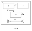
- According to another embodiment of the present invention illustrated in the block diagram in
Figure 6 , the second alarm signal is generated on the basis of the vehicle's position relative to the lane markings. - With reference to
Figure 6 , the invention thus comprises a lane departure warning system 2' for a vehicle 20', comprising a main monitoring unit 4' adapted to delivering a location signal 6' which indicates the vehicle's position relative to thelane markings 22 of a road, a lane deviation unit 8' adapted to calculating on the basis of said location signal 6' the vehicle's current deviation and the direction of deviation relative to the vehicle, and to generating on the basis thereof one or more deviation signals 10'. It further comprises an alarm unit 12' adapted to generating on the basis of said deviation signals 10' one or more alarm signals 14',16' to the vehicle's driver, the first alarm signal 14' being adapted to being generated if the vehicle's current deviation exceeds a first threshold value (T1,T1') which represents an impermissible deviation. The alarm unit is adapted to generating on the basis of said location signal a second alarm signal 16' which indicates the vehicle's position relative to the lane markings, in the form of an acoustic signal. - The vehicle's position relative to the lane markings is preferably indicated by altering the balance of its sound system, which takes place continuously depending on the vehicle's position relative to the lane markings.
- In other respects we cite the relevant sections of the description of the first embodiment which refer to configurations which may also be applicable for the second embodiment. For example, the intensity of the second alarm signal may change depending on the vehicle's position relative to the lane markings.
- The present invention comprises also a method pertaining to a lane departure warning system for a vehicle.
- With reference to
Figure 3 , the method comprises - a) determining the vehicle's position relative to the lane markings of a road,
- b) calculating the vehicle's current deviation and prospective deviations from its traffic lane and the direction of deviation relative to the vehicle, and generating on the basis thereof one or more deviation signals,
- c) generating on the basis of said deviation signals one or more alarm signals to the vehicle's driver, comprising a first alarm signal arranged to be generated if the vehicle's deviation exceeds a first threshold value which represents an impermissible deviation, and a second alarm signal arranged to be generated if said deviation signals indicate that the vehicle will impermissibly deviate from its traffic lane.
- The method further comprises:
- d) generating said second alarm signal in the form of a sound signal which indicates the direction of prospective deviation relative to the vehicle.
- The direction of prospective deviation is preferably indicated by altering the balance of the vehicle's sound system.
- According to an embodiment, the change in the sound balance takes place at a stage where the prospective deviation is less than the second threshold value or where the vehicle's position relative to the lane markings indicates a prospective deviation. Alternatively, the change in the sound balance takes place continuously depending on the vehicle's position relative to the lane markings.
- These embodiments were discussed in more detail above with reference to
Figures 4 and 5 . - The alarm unit is adapted to generating the second alarm signal when the deviation signal indicates that a prospective deviation is less than a predetermined second threshold value. The second threshold value may either represent a predetermined time before a deviation occurs or a predetermined distance between the vehicle and the lane markings. According to an embodiment of the method according to the present invention, the second alarm signal is variable in such a way that its intensity depends on how near in time the vehicle is to leaving its lane, or on the vehicle's distance to leaving its lane, so that the intensity of the second alarm signal increases continuously the nearer the vehicle is to leaving the lane.
- In all embodiments of the method according to the invention, if the deviation signal indicates that the prospective deviation will not occur, the alarm unit will preferably stop generating said second alarm signal.
- The invention comprises also a method which implements the lane departure warning system according to the second embodiment.
- This method comprises the steps of
- a) determining the vehicle's position relative to the lane markings of a road,
- b) calculating the vehicle's current deviation from its lane and the direction of deviation relative to the vehicle, and generating on the basis thereof one or more deviation signals,
- c) generating on the basis of said deviation signals one or more alarm signals comprising a first alarm signal arranged to be generated if the vehicle's deviation exceeds a first threshold value which represents an impermissible deviation.
- The method further comprises
- d) generating on the basis of said location signal a second alarm signal which indicates the vehicle's position relative to the lane markings, said second alarm signal being an acoustic signal.
- According to a method, the vehicle's position relative to the lane markings is indicated by altering the balance of the vehicle's sound system, which preferably takes place continuously depending on the vehicle's position relative to the lane markings.
- The present invention may be implemented in the form of software or in the form of one or more hardware items or in the form of a combination of software and hardware. The invention will then comprise a computer programme product with programme code for performing the various steps of the invention when the programme code is run on a computer.
- The present invention is not restricted to the preferred embodiments described above. Sundry alternatives, modifications and equivalents may be used. The above embodiments are therefore not to be regarded at limiting the invention's protective scope which is defined by the attached claims.
Claims (22)
- A lane departure warning system (2) for a vehicle (20), comprising a lane monitoring unit (4) adapted to delivering a location signal (6) which indicates the vehicle's position relative to the lane markings (22) (see Figure 2) of a road,
a lane deviation unit (8) adapted to calculating on the basis of said location signal (6) the vehicle's current deviation and prospective deviations from its lane, and the direction of deviation relative to the vehicle, and to generating on the basis thereof one or more deviation signals (10); and
an alarm unit (12) adapted to generating on the basis of said deviation signals (10) one or more alarm signals (14,16) to the vehicle's driver, comprising a first alarm signal (14) arranged to be generated if the vehicle's current deviation exceeds a first threshold value (T1,T1') which represents an impermissible deviation, and a second alarm signal (16) arranged to be generated if said deviation signal (10) indicates that the vehicle will impermissibly deviate from its lane, wherein
said second alarm signal (16) is an acoustic signal which indicates the direction of prospective deviation relative to the vehicle,
characterised in that the direction of prospective deviation is indicated by altering the balance of the vehicle's sound system. - The lane departure warning system according to claim 1, in which the change in the sound balance takes place at a stage where the prospective deviation is less than a second threshold value.
- The lane departure warning system according to claim 1, in which the change in the sound balance takes place at a stage where the vehicle's position relative to the lane markings indicates a prospective deviation.
- The lane departure warning system according to claim 1, in which the change in the sound balance takes place continuously depending on the vehicle's position relative to the lane markings.
- The lane departure warning system according to claim 1, in which the alarm unit is adapted to generating said second alarm signal when the deviation signal indicates that a prospective deviation is less than a predetermined second threshold value.
- A lane departure warning system according to claim 5, in which said second threshold value represents a predetermined time before a deviation occurs.
- A lane departure warning system according to claim 5, in which said second threshold value represents a predetermined distance between the vehicle and the lane markings.
- The lane departure warning system according to any one of the foregoing claims, in which said second alarm signal is variable in such a way that its intensity depends on how near in time the vehicle is to leaving its lane or on its distance to leaving the lane, so that the intensity of the second alarm signal increases continuously the nearer the vehicle is to leaving the lane.
- The lane departure warning system according to any one of the foregoing claims, in which if the deviation signal indicates that the prospective deviation will not occur the alarm unit stops generating said second alarm signal.
- A lane departure warning system (2') for a vehicle (20'), comprising a lane monitoring unit (4') adapted to delivering a location signal (6') which indicates the vehicle's position relative to the lane markings (22) of a road,
a lane deviation unit (8') adapted to calculating on the basis of said location signal (6') the vehicle's current deviation and the direction of deviation relative to the vehicle, and to generating on the basis thereof one or more deviation signals (10'), and
an alarm unit (12') adapted to generating on the basis of said deviation signals (10') one or more alarm signals (14',16') to the vehicle's driver, comprising a first alarm signal (14') arranged to be generated if the vehicle's current deviation exceeds a first threshold value (T1,T1') which represents an impermissible deviation, wherein said alarm unit is adapted to generating on the basis of said location signal a second alarm signal (16') which indicates the vehicle's position relative to the lane markings, and that said second alarm signal (16') is an acoustic signal,
characterised in that the vehicle's position relative to the lane markings is indicated by altering the balance of the vehicle's sound system. - The lane departure warning system according to claim 10, in which the change in the sound balance takes place continuously depending on the vehicle's position relative to the lane markings.
- A method pertaining to a lane departure warning system for a vehicle, comprising:a) determining the vehicle's position relative to the lane markings of a road,b) calculating the vehicle's current deviation and prospective deviations from its traffic lane and the direction of deviation relative to the vehicle, and generating on the basis thereof one or more deviation signals,c) generating on the basis of said deviation signals one or more alarm signals to the vehicle's driver, comprising a first alarm signal arranged to be generated if the vehicle's deviation exceeds a first threshold value which represents an impermissible deviation, and a second alarm signal arranged to be generated if said deviation signals indicate that the vehicle will impermissibly deviate from its traffic lane,d) generating said second alarm signal in the form of a sound signal which indicates the direction of prospective deviation relative to the vehicle,
characterised in that the method further comprises that:the direction of prospective deviation is indicated by altering the balance of the vehicle's sound system. - The method according to claim 12, in which the change in the sound balance takes place at a stage where the prospective deviation is less than a second threshold value.
- The method according to claim 12, in which the change in the sound balance takes place at a stage where the vehicle's position relative to the lane markings indicates a prospective deviation.
- The method according to claim 12, in which the change in the sound balance takes place continuously depending on the vehicle's position relative to the lane markings.
- The method according to claim 12, in which the alarm unit is adapted to generating said second alarm signal when the deviation signal indicates that a prospective deviation is less than a predetermined second threshold value.
- The method according to claim 16, in which said second threshold value represents a predetermined time before a deviation occurs.
- The method according to claim 16, in which said second threshold value represents a predetermined distance between the vehicle and the lane markings.
- The method according to claim according to any one of claims 12-18 above, in which said second alarm signal is variable in such a way that its intensity depends on how near in time the vehicle is to leaving its lane or its distance to leaving the lane, so that the intensity of the second alarm signal increases continuously the nearer the vehicle is to leaving the lane.
- The method according to any one of claims 12-19 above, in which if the deviation signal indicates that the prospective deviation will not occur the alarm unit stops generating said second alarm signal.
- A method pertaining to a lane departure warning system for a vehicle, comprisinga) determining the vehicle's position relative to the lane markings of a road,b) calculating the vehicle's current deviation from its lane and the direction of deviation relative to the vehicle, and generating on the basis thereof one or more deviation signals,c) generating on the basis said the deviation signals one or more alarm signals comprising a first alarm signal arranged to be generated if the vehicle's deviation exceeds a first threshold value which represents an impermissible deviation,d) generating on the basis of said location signal a second alarm signal which indicates the vehicle's position relative to the lane markings, and that said second alarm signal is an acoustic signal,
characterised in that the method further comprises that:the vehicle's position relative to the lane markings is indicated by altering the balance of the vehicle's sound system. - A method according to claim 21, in which the change in the sound balance takes place continuously depending on the vehicle's position relative to the lane markings.
Priority Applications (1)
| Application Number | Priority Date | Filing Date | Title |
|---|---|---|---|
| EP14164979.8A EP2767450A1 (en) | 2011-02-11 | 2012-02-09 | Lane departure warning system and a method for a lane departure warning system |
Applications Claiming Priority (1)
| Application Number | Priority Date | Filing Date | Title |
|---|---|---|---|
| SE1150108A SE536947C2 (en) | 2011-02-11 | 2011-02-11 | Lane guard system and a method for a lane guard system |
Related Child Applications (2)
| Application Number | Title | Priority Date | Filing Date |
|---|---|---|---|
| EP14164979.8A Division-Into EP2767450A1 (en) | 2011-02-11 | 2012-02-09 | Lane departure warning system and a method for a lane departure warning system |
| EP14164979.8A Division EP2767450A1 (en) | 2011-02-11 | 2012-02-09 | Lane departure warning system and a method for a lane departure warning system |
Publications (2)
| Publication Number | Publication Date |
|---|---|
| EP2487085A2 true EP2487085A2 (en) | 2012-08-15 |
| EP2487085A3 EP2487085A3 (en) | 2014-08-13 |
Family
ID=45655505
Family Applications (2)
| Application Number | Title | Priority Date | Filing Date |
|---|---|---|---|
| EP12154658.4A Withdrawn EP2487085A3 (en) | 2011-02-11 | 2012-02-09 | Lane departure warning system and a method for a lane departure warning system |
| EP14164979.8A Withdrawn EP2767450A1 (en) | 2011-02-11 | 2012-02-09 | Lane departure warning system and a method for a lane departure warning system |
Family Applications After (1)
| Application Number | Title | Priority Date | Filing Date |
|---|---|---|---|
| EP14164979.8A Withdrawn EP2767450A1 (en) | 2011-02-11 | 2012-02-09 | Lane departure warning system and a method for a lane departure warning system |
Country Status (3)
| Country | Link |
|---|---|
| EP (2) | EP2487085A3 (en) |
| CN (1) | CN102632835B (en) |
| SE (1) | SE536947C2 (en) |
Cited By (3)
| Publication number | Priority date | Publication date | Assignee | Title |
|---|---|---|---|---|
| WO2018041575A1 (en) * | 2016-09-05 | 2018-03-08 | Knorr-Bremse Systeme für Nutzfahrzeuge GmbH | Method for the open-loop or closed-loop control of a driver assistance system of a vehicle, and driver assistance system |
| CN114199267A (en) * | 2021-11-25 | 2022-03-18 | 交通运输部公路科学研究所 | Vehicle lane departure warning evaluation method, device and system |
| DE102022126876A1 (en) | 2022-10-14 | 2024-04-25 | Dr. Ing. H.C. F. Porsche Aktiengesellschaft | Method for assisting a user of a motor vehicle |
Families Citing this family (13)
| Publication number | Priority date | Publication date | Assignee | Title |
|---|---|---|---|---|
| CN103287430A (en) * | 2013-06-24 | 2013-09-11 | 成都衔石科技有限公司 | Lane departure warning device applied to car |
| KR101539302B1 (en) * | 2013-12-11 | 2015-07-30 | 현대자동차주식회사 | Vehicle and control method for the same |
| JP2016007894A (en) * | 2014-06-23 | 2016-01-18 | トヨタ自動車株式会社 | Alerting device and travel control device |
| JP6398951B2 (en) * | 2015-11-12 | 2018-10-03 | マツダ株式会社 | Lane maintenance control device |
| DE102015224711A1 (en) * | 2015-12-09 | 2017-06-14 | Robert Bosch Gmbh | Method for actuating a hydraulic braking device in a motor vehicle |
| CN105667515A (en) * | 2016-03-02 | 2016-06-15 | 江苏大学 | Lane departure early warning method based on fuzzy theory |
| CN106184206B (en) * | 2016-08-31 | 2018-12-14 | 威马汽车科技集团有限公司 | A kind of intelligent vehicle based on monocular vision principle is from road early warning system and method |
| CN107097794B (en) * | 2016-12-15 | 2020-04-21 | 财团法人车辆研究测试中心 | Road lane line detection system and method |
| JP2018144643A (en) * | 2017-03-06 | 2018-09-20 | トヨタ自動車株式会社 | Notification system and driver assistance system |
| CN108238101A (en) * | 2017-12-26 | 2018-07-03 | 潍柴动力股份有限公司 | For the automatic control system and autocontrol method of sweeper |
| CN109624975A (en) * | 2018-11-13 | 2019-04-16 | 上海建工集团股份有限公司 | Engineering transportation vehicle traveling monitoring method and system |
| SE544204C2 (en) * | 2020-04-15 | 2022-03-01 | Scania Cv Ab | Method and control arrangement for vehicle self-diagnosis |
| JP7795336B2 (en) * | 2021-12-01 | 2026-01-07 | 株式会社デンソーテン | Driving support device and driving support method |
Citations (4)
| Publication number | Priority date | Publication date | Assignee | Title |
|---|---|---|---|---|
| EP1074430A1 (en) | 1999-08-04 | 2001-02-07 | Iteris, Inc. | Imaging system and method with dynamic brightness control |
| EP1663711A1 (en) | 2003-09-08 | 2006-06-07 | Scania CV AB (publ) | Detection of unintended lane departures |
| US20090021358A1 (en) | 2007-07-16 | 2009-01-22 | Jae Kwan Lee | Lane deviation warning system |
| US20100295707A1 (en) | 2009-05-19 | 2010-11-25 | Brian Bennie | System and method for lane departure warning |
Family Cites Families (5)
| Publication number | Priority date | Publication date | Assignee | Title |
|---|---|---|---|---|
| DE10332961A1 (en) * | 2003-07-21 | 2005-02-17 | Robert Bosch Gmbh | Method and device for determining the position and / or the expected position of a vehicle during a parking operation in relation to the opposite lane of a multi-lane road |
| JP3982483B2 (en) * | 2003-11-13 | 2007-09-26 | 日産自動車株式会社 | Lane departure prevention device |
| TWI236990B (en) * | 2004-10-07 | 2005-08-01 | Chi-Ruei Huang | Pre-warning system of deviated lane for vehicles |
| US7561032B2 (en) * | 2005-09-26 | 2009-07-14 | Gm Global Technology Operations, Inc. | Selectable lane-departure warning system and method |
| DE102009015416B4 (en) * | 2009-03-27 | 2023-07-27 | Bayerische Motoren Werke Aktiengesellschaft | Procedure for warning the driver |
-
2011
- 2011-02-11 SE SE1150108A patent/SE536947C2/en unknown
-
2012
- 2012-02-08 CN CN201210027683.0A patent/CN102632835B/en active Active
- 2012-02-09 EP EP12154658.4A patent/EP2487085A3/en not_active Withdrawn
- 2012-02-09 EP EP14164979.8A patent/EP2767450A1/en not_active Withdrawn
Patent Citations (4)
| Publication number | Priority date | Publication date | Assignee | Title |
|---|---|---|---|---|
| EP1074430A1 (en) | 1999-08-04 | 2001-02-07 | Iteris, Inc. | Imaging system and method with dynamic brightness control |
| EP1663711A1 (en) | 2003-09-08 | 2006-06-07 | Scania CV AB (publ) | Detection of unintended lane departures |
| US20090021358A1 (en) | 2007-07-16 | 2009-01-22 | Jae Kwan Lee | Lane deviation warning system |
| US20100295707A1 (en) | 2009-05-19 | 2010-11-25 | Brian Bennie | System and method for lane departure warning |
Non-Patent Citations (1)
| Title |
|---|
| CRISTY HO; CHARLES SPENCE: "Assessing the Effectiveness of Various Auditory Cues in Capturing a Driver's Visual Attention", JOURNAL OF EXPERIMENTAL PSYCHOLOGY: APPLIED, vol. 11, no. 3, 2005, pages 157 - 174, Retrieved from the Internet <URL:http://www.apa.org/pubs/journals/features/xap-11-3-157.pdf> |
Cited By (4)
| Publication number | Priority date | Publication date | Assignee | Title |
|---|---|---|---|---|
| WO2018041575A1 (en) * | 2016-09-05 | 2018-03-08 | Knorr-Bremse Systeme für Nutzfahrzeuge GmbH | Method for the open-loop or closed-loop control of a driver assistance system of a vehicle, and driver assistance system |
| US11220263B2 (en) | 2016-09-05 | 2022-01-11 | Knorr-Bremse Systeme Fuer Nutzfahrzeuge Gmbh | Method for the open-loop or closed-loop control of a driver assistance system of a vehicle, and driver assistance system |
| CN114199267A (en) * | 2021-11-25 | 2022-03-18 | 交通运输部公路科学研究所 | Vehicle lane departure warning evaluation method, device and system |
| DE102022126876A1 (en) | 2022-10-14 | 2024-04-25 | Dr. Ing. H.C. F. Porsche Aktiengesellschaft | Method for assisting a user of a motor vehicle |
Also Published As
| Publication number | Publication date |
|---|---|
| CN102632835A (en) | 2012-08-15 |
| CN102632835B (en) | 2014-07-23 |
| EP2487085A3 (en) | 2014-08-13 |
| SE536947C2 (en) | 2014-11-11 |
| SE1150108A1 (en) | 2012-08-12 |
| EP2767450A1 (en) | 2014-08-20 |
Similar Documents
| Publication | Publication Date | Title |
|---|---|---|
| EP2487085A2 (en) | Lane departure warning system and a method for a lane departure warning system | |
| US11590890B2 (en) | Method and system for augmented alerting based on driver's state in hybrid driving | |
| US11511752B2 (en) | Method and system for risk based driving mode switching in hybrid driving | |
| CN106274480B (en) | Method and apparatus for enabling secondary tasks during semi-autonomous driving | |
| US9007198B2 (en) | Adaptive Actuator interface for active driver warning | |
| CN103794072B (en) | Method and the vehicle exceeding speed limit alarm is sent to vehicle driver | |
| JP2021523427A (en) | Methods and systems for switching operation modes based on self-awareness parameters in hybrid operation | |
| US9908410B2 (en) | Method and device for warning the driver of a motor vehicle in the event of lack of attention | |
| US11745745B2 (en) | Systems and methods for improving driver attention awareness | |
| US20160214531A1 (en) | Method and system for a warning message in a vehicle | |
| WO2018163470A1 (en) | Driving mode switching control device, system, and method | |
| CN116867697A (en) | Physical feedback confirmation of traffic events by assisted driving systems | |
| WO2022258150A1 (en) | Computer-implemented method of assisting a driver, computer program product, driving assistance system, and vehicle | |
| JP2006343904A (en) | Driving support device | |
| JP2017167623A (en) | Information display device, information display method, and program | |
| EP3729398A1 (en) | Method and system for risk control in switching driving mode | |
| CA3083411C (en) | Method and system for adapting augmented switching warning | |
| WO2015012757A1 (en) | System and method for continuous distance monitoring | |
| EP2463172B1 (en) | Safety system for a vehicle and a method for a safety system | |
| CN117985036A (en) | HMI interaction method and system based on cooperative V2X | |
| JP2020095421A (en) | Information presentation system, information presentation processing device, and program thereof |
Legal Events
| Date | Code | Title | Description |
|---|---|---|---|
| PUAI | Public reference made under article 153(3) epc to a published international application that has entered the european phase |
Free format text: ORIGINAL CODE: 0009012 |
|
| AK | Designated contracting states |
Kind code of ref document: A2 Designated state(s): AL AT BE BG CH CY CZ DE DK EE ES FI FR GB GR HR HU IE IS IT LI LT LU LV MC MK MT NL NO PL PT RO RS SE SI SK SM TR |
|
| AX | Request for extension of the european patent |
Extension state: BA ME |
|
| PUAL | Search report despatched |
Free format text: ORIGINAL CODE: 0009013 |
|
| AK | Designated contracting states |
Kind code of ref document: A3 Designated state(s): AL AT BE BG CH CY CZ DE DK EE ES FI FR GB GR HR HU IE IS IT LI LT LU LV MC MK MT NL NO PL PT RO RS SE SI SK SM TR |
|
| AX | Request for extension of the european patent |
Extension state: BA ME |
|
| RIC1 | Information provided on ipc code assigned before grant |
Ipc: B62D 15/02 20060101ALI20140710BHEP Ipc: H04S 3/00 20060101ALI20140710BHEP Ipc: B60W 50/14 20120101AFI20140710BHEP |
|
| 17P | Request for examination filed |
Effective date: 20150213 |
|
| RBV | Designated contracting states (corrected) |
Designated state(s): AL AT BE BG CH CY CZ DE DK EE ES FI FR GB GR HR HU IE IS IT LI LT LU LV MC MK MT NL NO PL PT RO RS SE SI SK SM TR |
|
| 17Q | First examination report despatched |
Effective date: 20180718 |
|
| STAA | Information on the status of an ep patent application or granted ep patent |
Free format text: STATUS: THE APPLICATION IS DEEMED TO BE WITHDRAWN |
|
| 18D | Application deemed to be withdrawn |
Effective date: 20190129 |
|
| P01 | Opt-out of the competence of the unified patent court (upc) registered |
Effective date: 20230516 |