EP2487041A2 - Image forming apparatus with cover - Google Patents
Image forming apparatus with cover Download PDFInfo
- Publication number
- EP2487041A2 EP2487041A2 EP12154748A EP12154748A EP2487041A2 EP 2487041 A2 EP2487041 A2 EP 2487041A2 EP 12154748 A EP12154748 A EP 12154748A EP 12154748 A EP12154748 A EP 12154748A EP 2487041 A2 EP2487041 A2 EP 2487041A2
- Authority
- EP
- European Patent Office
- Prior art keywords
- cover
- support member
- image forming
- forming apparatus
- main body
- Prior art date
- Legal status (The legal status is an assumption and is not a legal conclusion. Google has not performed a legal analysis and makes no representation as to the accuracy of the status listed.)
- Granted
Links
Images


Classifications
-
- B—PERFORMING OPERATIONS; TRANSPORTING
- B41—PRINTING; LINING MACHINES; TYPEWRITERS; STAMPS
- B41J—TYPEWRITERS; SELECTIVE PRINTING MECHANISMS, i.e. MECHANISMS PRINTING OTHERWISE THAN FROM A FORME; CORRECTION OF TYPOGRAPHICAL ERRORS
- B41J29/00—Details of, or accessories for, typewriters or selective printing mechanisms not otherwise provided for
- B41J29/12—Guards, shields or dust excluders
- B41J29/13—Cases or covers
Landscapes
- Accessory Devices And Overall Control Thereof (AREA)
- Sealing Devices (AREA)
- Casings For Electric Apparatus (AREA)
Abstract
Description
- This disclosure relates to an image forming apparatus, such as an inkjet recording apparatus, a thermal or other type of information recording apparatus, a copier, a facsimile machine, a printer, a plotter, a word processor, or a multi-functional device having two or more of the foregoing capabilities and a cover used in the image forming apparatus, and more specifically to an image forming apparatus capable of preventing dust from entering, adhering to, or accumulating on the image forming apparatus and a dustproof cover used in the image forming apparatus.
- Image forming apparatuses are used as printers, facsimile machines, copiers, plotters, or multi-functional devices having two or more of the foregoing capabilities. To prevent dirt or dust from entering its interior or adhering to or accumulating on its exterior surface, a dustproof cover (hereinafter, also simply referred to as "cover") may be employed to entirely cover an image forming apparatus. Typically, such a cover is used during non-operation of the apparatus and removed during operation of the apparatus. However, a cover may be needed during operation, in particular, when such an image forming apparatus is used in a dusty environment. Hence, some conventional dustproof covers are proposed that have an opening and an opening-and-closing unit to open and close the opening so as to enable a user to operate the image forming apparatus, pick up a sheet or recording media, and replace inks with the cover being put on the apparatus.
- For example,
JP-H11-334175-A - However, in such conventional configurations including that described in
JP-H11-334175-A - In an aspect of this invention, there is provided an image forming apparatus including a main body, a cover member, and a support member. The main body has a bottom face opposing a surface on which the image forming apparatus rests. The cover member is at least partially flexible, has a bottom opening, and is dimensioned to entirely cover the image forming apparatus except for the bottom face of the image forming apparatus. The support member is pivotably supported on the main body. The support member has base end portions supported on the main body and a front end portion to support a portion of the cover member. With a pivotal movement of the support member, the cover member displaces and deforms and an end of the bottom opening of the cover member moves upward to expose a portion of the image forming apparatus to be accessed by a user operating the image forming apparatus.
- The aforementioned and other aspects, features, and advantages of the present disclosure would be better understood by reference to the following detailed description when considered in connection with the accompanying drawings, wherein:
-
FIG 1 is an exterior perspective view of a printer mounting a cover according to a first exemplary embodiment seen from a front side of the printer; -
FIG 2 is a side view of an entire configuration of a mechanical section of the printer; -
FIG 3 is a plan view of a portion of the mechanical section ofFIG 2 ; -
FIG 4 is a side view of the cover and the printer illustrating operation of the cover and a support member in the first exemplary embodiment; -
FIG 5 is a side view of a cover and a printer according to a second exemplary embodiment illustrating operation of the cover and a support member; -
FIG 6 is an exterior perspective view of a printer mounting a cover according to a third exemplary embodiment seen from a front side of the printer; -
FIG 7 is a side view of the printer ofFIG 6 illustrating operation of the cover and a support member; -
FIG 8A is a side view of a cover and a printer according to a fourth exemplary embodiment illustrating operation of the cover and a support member; and -
FIG 8B is an enlarged view of a sliding mechanism illustrated inFIG 8A . - The accompanying drawings are intended to depict exemplary embodiments of the present disclosure and should not be interpreted to limit the scope thereof. The accompanying drawings are not to be considered as drawn to scale unless explicitly noted.
- In describing embodiments illustrated in the drawings, specific terminology is employed for the sake of clarity. However, the disclosure of this patent specification is not intended to be limited to the specific terminology so selected and it is to be understood that each specific element includes all technical equivalents that operate in a similar manner and achieve similar results.
- Although the exemplary embodiments are described with technical limitations with reference to the attached drawings, such description is not intended to limit the scope of the invention and all of the components or elements described in the exemplary embodiments of this disclosure are not necessarily indispensable to the present invention.
- Referring now to the drawings, exemplary embodiments of the present disclosure are described below. In the following exemplary embodiments, the same reference characters are allocated to elements (members or components) having the same function and shape and redundant descriptions thereof are omitted below. Additionally, for sake of simplicity and clearness, elements considered to require no specific descriptions may be omitted from drawings.
- First exemplary embodiment
- With reference to
FIGS. 1 to 3 , first, an entire configuration and operation of a printer serving as an inkjet recording apparatus which is an example of an image forming apparatus according to a first exemplary embodiment of this disclosure. -
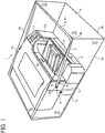
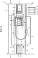
FIG 1 is an exterior perspective view of the printer with a cover mounted thereon seen from the front side of the printer.FIG 2 is a side view of an entire configuration of a mechanical section of the printer.FIG 3 is a plan view of a portion of the mechanical section ofFIG 2 . The front side of the printer is located at the right side inFIG 2 and the lower side inFIG 3 . - The inkjet recording apparatus illustrated in
FIGS. 1 to 3 is a printer serving as a serial-type inkjet recording apparatus. InFIGS. 1 to 3 , theprinter 1 has amain body 1A, asheet feed tray 2, and thesheet output tray 3. Themain body 1A includes aframe 20 forming a skeleton of theprinter 1 and exterior panels forming a housing of theprinter 1. Thesheet feed tray 2 is mounted in themain body 1A and serves as a sheet accommodation unit to accommodate sheets. Thesheet output tray 3 is removably mounted in themain body 1A and serves as a sheet stack unit on which sheets having images recorded/formed are stacked. Each of thesheet feed tray 2 and thesheet output tray 3 is partially exposed to the outside of themain body 1A. As illustrated inFIGS. 1 and2 , above thesheet output tray 3 is formed a sheet output opening 3a serving as a space through which sheets having images formed thereon are discharged. - At one end portion of the front side of the
main body 1A (near a lateral side of the sheet output tray 3) is disposed a cartridge mounting portion 5 (seeFIG 3 ) having afront cover 5a to open and close cartridge mounting ports into which liquid cartridges are mounted/inserted. The cartridge mounting portion 5 protrudes forward from the front side of themain body 1A and is disposed at a position lower than an upper face of themain body 1A. At an upper face of the cartridge mounting portion 5 is disposed acontrol panel 4 serving as an operation-and-display unit having operation buttons and a display. As illustrated inFIG 1 , theprinter 1 also has acover 6, asupport member 7, andattachment members 8. - As illustrated in
FIG 3 ,liquid cartridges main body 1A toward the rear side of themain body 1A to be mounted in the cartridge mounting portion 5. Theliquid cartridges - The
control panel 4 includes remaining-quantity indicators indicating that the remaining quantities of the respective color liquids in theliquid cartridges control panel 4, the remaining-quantity indicators are disposed at positions corresponding to the mount positions of theliquid cartridges control panel 4. - As described above, the
printer 1 has a front operation design to enable a user to pick up a sheet having an image formed thereon from thesheet output tray 3, operate buttons of thecontrol panel 4, and handle the cartridge mounting portion 5 with the user opposing the front face of themain body 1A illustrated inFIG 1 . In using theprinter 1 as the image forming apparatus, the user accesses, for example, thesheet feed tray 2, the sheet output tray 3, thecontrol panel 4, and the cartridge mounting portion 5. - As illustrated in
FIG 3 , themain body 1A has two, left and right,main side plates rear plate 24 forming theframe 20. As illustrated inFIG 3 , amain guide rod 31 and asub guide rod 32 serving as guide members extend between themain side plates main guide rod 31 and thesub guide rod 32 support thecarriage 33 so that thecarriage 33 is slidable in a main scanning direction indicated by a double arrow MSD inFIG 3 . Thecarriage 33 is reciprocally moved for scanning in the main scanning direction MSD by a main scanning motor via a timing belt. - On the
carriage 33 are mounted recording heads (droplet ejection heads) 34 having multiple nozzle rows to eject droplets of the different color liquids of black (K), cyan (C), magenta (M), and yellow (Y). - On the
carriage 33 is mounted a plurality ofliquid tanks 35 to supply the different color liquids to the respective recording heads 34. The different color inks are replenished from the respective liquid cartridges 10 mounted in the cartridge mounting portion 5 to theliquid tanks 35 viaflexible supply tubes 36 dedicated for the respective colors. In the cartridge mount portion 5 is mounted a supply-pump unit to feed liquids from the liquid cartridges 10. A holdingmember 37 holds thesupply tubes 36 on astay 29 indicated by a broken line inFIG 3 . - As illustrated in
FIG 2 , theprinter 1 further includes a sheet feed section to feedsheets 42 stacked on a sheet stack portion (platen) 41 of thesheet feed tray 2. The sheet feed section includes a sheet feed roller 43 and aseparation pad 44. The sheet feed roller 43 of, e.g., a half moon shape separates thesheets 42 from thesheet stack portion 41 and feeds thesheets 42 sheet by sheet. Theseparation pad 44 is disposed facing the sheet feed roller 43, is made of a material of a high friction coefficient, and is urged toward the sheet feed roller 43. To feed thesheet 42 from the sheet feed section to a position below the recording heads 43, theprinter 1 has afirst guide member 45 to guide thesheet 42, acounter roller 46, aconveyance guide member 47, apress member 48 including a front-end press roller 49, and aconveyance belt 51 serving as a conveyance unit to convey thesheet 42 to a position opposing the recording heads 34 with thesheet 42 electrostatically adhered on theconveyance belt 51. - The
conveyance belt 51 is an endless belt looped around aconveyance roller 52 and atension roller 53 so as to circulate in a belt conveyance direction (sub-scanning direction). - The
printer 1 also has a chargingroller 56 serving as a charging unit to charge an outer surface of theconveyance belt 51. The chargingroller 56 is disposed so as to contact the outer surface of theconveyance belt 51 and rotate with the circulation of theconveyance belt 51. On the reverse (inner) side of theconveyance belt 51, asecond guide member 57 serving as a platen unit is disposed at a position corresponding to a printing (recording) area of the recording heads 34. Theconveyance roller 52 is rotated by a sub-scanning motor via a timing roller, so that theconveyance belt 51 circulates in the belt conveyance direction, that is, the sub-scanning direction indicated by an arrow SSD inFIG 3 . - As illustrated in
FIG 2 , aduplex unit 71 is mounted on a rear portion of themain body 1A. When theconveyance belt 51 rotates in reverse to return thesheet 42, theduplex unit 71 receives thesheet 42. Then theduplex unit 71 turns thesheet 42 around to feed thesheet 42 again to a position between thecounter roller 46 and theconveyance belt 51. - As illustrated in
FIG 3 , the image forming apparatus further includes a sheet output section to output thesheet 42 having an image formed by the recording heads 43. The sheet output section includes aseparation claw 61 to separate thesheet 42 from theconveyance belt 51, afirst output roller 62, asecond output roller 63, and thesheet output tray 3 disposed below thefirst output roller 62. - As illustrated in
FIG 3 , amaintenance unit 81 is disposed at a non-printing (non-recording) area that is located at one end in the main-scanning direction of thecarriage 33. Themaintenance unit 81 maintains and recovers nozzle conditions of the recording heads 34. Themaintenance unit 81 includescaps 82 to collectively cover the nozzles of the recording heads 34, awiper blade 83 serving as a blade member to wipe the nozzle faces of the recording heads 34, and afirst droplet receptacle 84 to receive liquid droplets discharged during maintenance ejection in which liquid droplets not contributing to a recorded image are discharged to remove increased-viscosity recording liquid from the nozzles of the recording heads. - Waste recording liquid discharged in such maintenance-and-recovery operation of the
maintenance unit 81, liquid discharged to thecaps 82, liquid adhered to thewiper blade 83 and wiped with a wiper cleaner, and liquid (ink) discharged to thefirst droplet receptacle 84 are accommodated in a waste tank. - As illustrated in
FIG 3 , asecond droplet receptacle 88 is disposed at a non-printing area on the other end in the main-scanning direction of thecarriage 33. Thesecond droplet receptacle 88 receives liquid droplets that are discharged to remove increased-viscosity recording liquid during, e.g., recording (image forming) operation. Thesecond droplet receptacle 88 hasopenings 89 arranged in parallel with the rows of nozzles of the recording heads 134. - Next, operation of the printer having the above-described configuration is described with reference to
FIGS. 2 and3 . - First, the sheet feed roller 43 and the
separation pad 44 cooperate to separate and feed thesheets 42 sheet by sheet from thesheet feed tray 2. Thesheet 42 is fed upward in a substantially vertical direction, guided along thefirst guide member 45, and conveyed between theconveyance belt 51 and thecounter roller 46. Further, the front edge of thesheet 42 is guided along theconveyance guide member 47 and pressed against theconveyance belt 51 by the front-end press roller 49 to turn the transport direction of thesheet 42 by substantially 90 degrees. - At this time, the
conveyance roller 52 is rotated by the sub-scanning motor, so that theconveyance belt 51 circulates in the sub-scanning direction (belt conveyance direction) indicated by the arrow SSD inFIG 3 . Meanwhile, an AC (alternating current) bias supply unit of a controller alternately supplies positive and negative voltages to the chargingroller 56 so that theconveyance belt 51 is charged with an alternating voltage pattern, that is, an alternating band pattern of positively-charged band areas and negatively-charged band areas. - When the
sheet 42 is fed onto theconveyance belt 51 alternately charged with positive and negative charges, thesheet 42 is adhered onto theconveyance belt 51 and conveyed in the sub-scanning direction with the circulation of theconveyance belt 51. By driving the recording heads 34 in response to image signals while moving thecarriage 33, liquid (ink) droplets are ejected on thesheet 42 stopped below the recording heads 43 to form one line of a desired image. After thesheet 42 is fed by a certain amount, another line of the image is recorded on thesheet 42. - Then, the
sheet 42 is conveyed by theconveyance belt 51 with the rotation of theconveyance roller 52. Thesheet 42 having the image formed thereon is separated from theconveyance belt 51 with theseparation claw 61 which is pivotably disposed between thetension roller 53 and theconveyance roller 52. Thesecond output roller 63 is rotated with the rotation of thefirst output roller 62 to feed thesheet 42. Receiving a signal indicating that the image has been recorded or that the rear edge of thesheet 42 has arrived at the printing (recording) area, the recording heads 43 finish the recording operation and thesheet 42 is outputted to thesheet output tray 3. - In waiting for the next recording (printing) operation, the
carriage 33 is shifted to a position above themaintenance unit 81 and the nozzle faces of the recording heads 34 are sealed with thecaps 82. Thus, the moisture in the nozzles is kept to prevent an ejection failure due to ink drying. With the nozzle faces of the recording heads 34 sealed with thecaps 82, a suction pump suctions recording liquid from the nozzles to remove increased-viscosity liquid (ink or other recording liquid) or air bubbles. Thus, recovery operation is performed. Further, before or during a recording operation, the above-described maintenance ejection is performed in which ink not contributing to a recorded image is discharged for maintenance. Such maintenance ejection allows stable ejection performance of the recording heads 34. Descriptions of operation of theprinter 1 during duplex printing with theduplex unit 71 are omitted for simplicity. - Next, the
cover 6, thesupport member 7, and theattachment member 8 are described with reference toFIGS. 1 to 4 . - In
FIG 1 , no sheets having images formed thereon are discharged or stacked on thesheet output tray 3.FIG 4 is a side view of theprinter 1 illustrated to describe operation of thecover 6 and thesupport member 7 in the first exemplary embodiment. - The
cover 6 is a sheet-type flexible cover member serving as a dustproof cover mounted on theprinter 1 to prevent dirt or dust from adhering to or accumulating on theprinter 1. The same applies to acover 6A according to another exemplary embodiment illustrated inFIGS. 6 and7 . Typically, theprinter 1 rests on asurface 25, such as a table or floor surface, via mountingportions 1b disposed on abottom surface 1a so as to protrude downward from thebottom surface 1a. - The
cover 6 has a substantially rectangular parallelepiped shape to entirely cover theprinter 1 except for thebottom surface 1a, in which abottom opening 6a is opened opposing thebottom surface 1a. The shape of thecover 6 is maintained by themain body 1A and thesupport member 7. Such a configuration allows a user to mount and remove thecover 6 onto and from theprinter 1 by simple operation. In other words, the user can mount thecover 6 onto theprinter 1 by simply putting thecover 6 onto an upper portion of theprinter 1 through thebottom opening 6a of thecover 6, and remove or detach thecover 6 from theprinter 1 by simply picking up anupper portion 6d of thecover 6 by his/her hand. - The
cover 6 is preferably made of flexible material, for example, polyvinyl chloride (PVC) or other plastic, to displace or deform in response to movement of thesupport member 7. At least a portion or the entire of thecover 6 may be made of light-transmissive, transparent or semi-transparent material to enable a user to see the inside of thecover 6 and easily operate theprinter 1. For example, at at least an area corresponding to parts which a user need access from the outside of thecover 1 to use theprinter 1, thecover 6 preferably has a transparent portion(s) allowing the user to see the parts, such as, thesheet feed tray 2, thesheet output tray 3, thecontrol panel 4, and the cartridge mounting portion 5. - The
cover 6 of the substantially rectangular parallelepiped shape protrudes corresponding to thesheet output tray 3 extending forward from the front side of themain body 1A so as to have a relatively large space at a side close to thesheet output tray 3. Thecover 6 has anupper corner portion 6c of a substantially right angle shape engageable with afront end portion 7a of thesupport member 7. - The
support member 7 is made of, for example, resin or metal material having a cylindrical shape in cross section. Thesupport member 7 protrudes forward of themain body 1A correspondingly to the shape of thecover 6 to obtain a space in which thesheet 42 having an image formed thereon is discharged from thesheet output opening 3a to thesheet output tray 3 at the front face of themain body 1A. Thesupport member 7 also has a substantially U-shape on a plan view and substantially the same width as a width of themain body 1A to support thecover 6 of the substantially rectangular parallelepiped shape covering theprinter 1 by a single component, that is, thesupport member 7. In this exemplary embodiment,base end portions 7b of lateral sides of the substantiallyU-shaped support member 7 are pivotably supported at respective side faces 1c of themain body 1A viaattachment members 8. Thefront end portion 7a of thesupport member 7 pivotably supports theupper corner portion 6c of thecover 6. - The
base end portions 7b of the lateral sides of thesupport member 7 are supported byshafts 8a of theattachment members 8 fixed at theprinter 1 so as to be pivotable around theshafts 8a. As a result, as illustrated inFIG 4 , thefront end portion 7a of thesupport member 7 is pivotable on an arc-shapedmovement trajectory 15 around therespective shafts 8a. The positions of supported points of thebase end portions 7b of thesupport member 7 are not limited to the positions illustrated inFIG 4 but may be any other positions/places. However, preferably, as illustrated inFIG 4 , the positions of supported points of thebase end portions 7b are placed higher than thesheet output opening 3a. - When the
support member 7 is placed at an initial position P1 illustrated inFIG 1 , thebase end portions 7bcontact stopper members 9 protruding outward from therespective attachment members 8, thus preventing thesupport member 7 from pivoting to a position lower than the initial position P1. - The
attachment members 8 may be fixed relative to themain body 1A of theprinter 1 with, for example, double-faced adhesive tapes. Alternatively, theattachment members 8 may be fixed with, for example, screws or fitting clips so as to be removably mountable relative to themain body 1A. It is to be noted that theattachment members 8 may be not necessary and, for example, thebase end portions 7b of thesupport member 7 may be directly supported by themain body 1A in a pivotable manner. In other words, any other member or mechanism other than those described above can be used to pivot thesupport member 7 relative to themain body 1A. - By pivoting the
front end portion 7a of thesupport member 7 counterclockwise from the initial position P1 illustrated inFIGS. 1 and4 around theshafts 8a, theupper corner portion 6c of thecover 6 engaging thefront end portion 7a is lifted up along the arc-shapedmovement trajectory 15 while thecover 6 displaces and deforms. As a result, an end (hereinafter "bottom opening end 6b") of thebottom opening 6a at a front side of the cover 6 (front right side inFIG 1 ) is lifted up to a position to open the parts, such as thesheet output tray 3 and thesheet output opening 3 a, to which a user need access in using theprinter 1, thus allowing the user's accessing parts at the front face of the printer 1 (e.g., thesheet feed tray 2, thesheet output tray 3, thesheet output opening 3a, thecontrol panel 4, and the cartridge mounting portion 5) to be widely opened to the outside of thecover 6. Such a configuration allows the user to operate and check theprinter 1, replenish or replace consumables, such as sheets and ink, and pick up output sheets without removing thecover 6. - The configuration and operation are further described below with reference to
FIG 4 . - With the
support member 7 placed at the initial position P1, a user can hold thefront end portion 7a of thesupport member 7 by his/her hand via theupper corner portion 6c of thecover 6. In picking up thesheet 42 from thesheet output tray 3, the user holds thefront end portion 7a of thesupport member 7 at the initial position P1 via theupper corner portion 6c of thecover 6 by one hand and lifts thesupport member 7 to a first open position P2 (hereinafter, simply "open position P2") indicated by a broken line inFIG 4 so that thesupport member 7 pivots counterclockwise around theshafts 8a along the arc-shapedmovement trajectory 15. At this time, while thecover 6 displaces and deforms, thebottom opening end 6b of the front side of thecover 6 is lifted to a position upper than thesheets 42 stacked on thesheet output tray 3, thus allowing the user to pick up thesheets 42 by the other hand. - When the user releases the hand from the
front end portion 7a at the open position P2, thesupport member 7 returns to the initial position P1 clockwise along the arc-shapedmovement trajectory 15 by its weight, thus allowing simple operation. In checking theprinter 1 or replenishing or replacing consumables, such as sheets and ink, the user holds thefront end portion 7a of thesupport member 7 via theupper corner portion 6c of thecover 6 and further pivots thefront end portion 7a from the open position P2 to a second open position P3 (hereinafter, simply "open position P3") indicated by another broken line inFIG 4 . At this time, while thecover 6 further displaces and deforms, thefront end portion 7a of thesupport member 7 contacts the upper face of themain body 1A. As a result, the front face and substantially half of the upper face of themain body 1A are largely opened to the outside, thus facilitating the user's operation. - As described above, this exemplary embodiment obviates a special opening, except for the
bottom opening 6a generally used to mount and remove thecover 6 to and from theprinter 1 serving as the image forming apparatus, and an opening-and-closing unit for opening and closing such a special opening. This exemplary embodiment can also provide thedustproof cover 6 facilitating user's access to parts of theprinter 1, such as thesheet feed tray 2, thesheet output tray 3, thecontrol panel 4, and the cartridge mounting portion 5, and theprinter 1 having thedustproof cover 6. Thecover 6 is made of flexible and elastic material, thus allowing a reduced size of theentire cover 6. At least a portion of thecover 6 corresponding to the parts of theprinter 1, such as thesheet feed tray 2, thesheet output tray 3, thecontrol panel 4, and the cartridge mounting portion 5, which a user need access in operating theprinter 1 is made of light-transmittable material, thus allowing the user to see the inside of thecover 6. - Second exemplary embodiment
- A second exemplary embodiment of this disclosure is described with reference to
FIG 5 . -
FIG 5 is a side view of acover 6 and aprinter 1 according to the second exemplary embodiment illustrating operation of thecover 6 and asupport member 7 in the second exemplary embodiment. - The second exemplary embodiment differs from the first exemplary embodiment of
FIGS. 1 to 4 in that thecover 6 of the second exemplary embodiment has such a size that, when thesupport member 7 pivots, abottom opening end 6b at a front side of thecover 6 does not contactsheets 42 stacked on thesheet output tray 3. Except for the difference, the configuration of the second exemplary embodiment is substantially the same as the configuration of the first exemplary embodiment illustrated inFIGS. 1 to 4 . - In
FIG 5 , abroken line 17 indicates a trajectory of movement of thebottom opening end 6b at the front side of thecover 6 drawn when thesupport member 7 pivots. In this exemplary embodiment, the length of thesupport member 7 from thebase end portions 7b to thefront end portion 7a is set to such a length that thesheets 42 discharged and stacked on thesheet output tray 3 do not intersect themovement traj ectory 17 of thebottom opening end 6b. In other words, by specifying themovement trajectory 17 of thebottom opening end 6b, this exemplary embodiment clearly defines that thesupport member 7 has such a length that, while thesupport member 7 pivots, thesheet 42 discharged and stacked on thesheet output tray 3 do not contact themovement trajectory 17 of thebottom opening end 6b. - Accordingly, besides advantages and effects equivalent to those of the first exemplary embodiment, this second exemplary embodiment also allows a user to securely pick up the
sheet 42 from thesheet output tray 3 without being hampered by thecover 6 because, even when the user lifts up thefront end portion 7a of thesupport member 7 to the open position P2 to pick up thesheet 42 on thesheet output tray 3, thebottom opening end 6b of thecover 6 does not contact thesheets 42 stacked on thesheet output tray 3. Such a configuration facilitates the user to pick up thesheets 42 from thesheet output tray 3. - Third exemplary embodiment
- A third exemplary embodiment of this disclosure is described with reference to
FIGS. 6 and7 . -
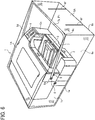
FIG 6 is an exterior perspective view of aprinter 1 with acover 6A mounted thereon according to the third exemplary embodiment seen from the front side of theprinter 1.FIG 7 is a side view of thecover 6A and theprinter 1 illustrating operation of thecover 6A and asupport member 7A in the third exemplary embodiment. - The third exemplary embodiment differs from the second exemplary embodiment illustrated in
FIG 5 in that thecover 6A is used in the third exemplary embodiment instead of thecover 6 of the second exemplary embodiment. Except for the difference, the configuration of the third exemplary embodiment is substantially the same as the configuration of the second exemplary embodiment illustrated inFIG 5 . - The
cover 6A differs from thecover 6 in that thecover 6A has twoslits 6f opposing thesheet output tray 3 and extending upward from abottom opening end 6b. Theslits 6f are also arranged to have an interval of substantially the same size to the size of thesheet 42 in the width direction (more specifically, the maximum size in the width direction of the sheet usable in the printer 1). - In the second exemplary embodiment of
FIG 5 , thesupport member 7 has a relatively long length such that themovement trajectory 17 of thebottom opening end 6b at the front side of thecover 6 does not contact thesheets 42 on thesheet output tray 3. By contrast, as in this third exemplary embodiment, even in a case in which thesheets 42 on thesheet output tray 3 intersect amovement trajectory 17 of thebottom opening end 6b at the front side of thecover 6A, the above-described twoslits 6f limit deformation of thecover 6A, caused by contact with thesheets 42 on thesheet output tray 3, to an area between theslits 6f, thus preventing thecover 6A from hampering the pivotal movement of thesupport member 7A. - Accordingly, besides advantages and effects equivalent to those of the second exemplary embodiment, this third exemplary embodiment can employ a shorter length of the
support member 7 than that of the second exemplary embodiment, thus allowing a reduction in the entire size of thecover 6A as compared to thecover 6 of the second exemplary embodiment. - Fourth exemplary embodiment
- A fourth exemplary embodiment of this disclosure is described with reference to
FIG 8 . -
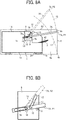
FIG 8A is a side view of acover 6 and aprinter 1 according to the fourth exemplary embodiment illustrating operation of thecover 6 and asupport member 7A in the fourth exemplary embodiment.FIG 8B is an enlarged view of a sliding mechanism ofFIG 8A . - The fourth exemplary embodiment differs from the second exemplary embodiment illustrated in
FIG 5 in that, in the fourth exemplary embodiment, asupport member 7A is employed instead of thesupport member 7 of the second exemplary embodiment and that a sliding mechanism is employed as a support unit to supportbase end portions 7b of thesupport member 7A. Except for the difference, the configuration of the fourth exemplary embodiment is substantially the same as the configuration of the second exemplary embodiment illustrated inFIG 5 . - The
support member 7A differs from thesupport member 7 ofFIG 5 in that each of thebase end portions 7b has aslot 19 formed along a longitudinal direction of thesupport member 7A and that each of thebase end portions 7b has apin 12 protruding from an inner side of thesupport member 7A (a back side inFIGS. 8A and 8B ) inward relative to aside face 1c of theprinter 1. Additionally,attachment members 8 in the fourth exemplary embodiment differ from those of the above-described exemplary embodiments in that, instead of theshaft 8a, each ofattachment members 8 in the fourth exemplary embodiment has apin 18 protruding outward relative to theside face 1c of theprinter 1 to loosely fit into theslot 19 to slidingly guide thesupport member 7A in the longitudinal direction of thesupport member 7A and aslot 13 loosely fitting with thepin 12 to guide thepin 12 with the movement of thesupport member 7A between the initial position P1 and the open position P2 (in other words, theslot 13 is formed along a direction in which thepin 12 moves when thesupport member 7A moves between an initial position P1 and an open position P2). - Operation in this fourth exemplary embodiment is described below mainly with respect to differences from the second exemplary embodiment.
- With the
support member 7A placed at the initial position P1, a user can hold afront end portion 7a of thesupport member 7A by his/her hand via theupper corner portion 6c of thecover 6. To pickup thesheets 42 from thesheet output tray 3, the user holds thefront end portion 7a of thesupport member 7A placed at the initial position P1 via theupper corner portion 6c of thecover 6 by one hand (at this time, theimmovable pin 18 is fitted into theslot 19 in contact with the right end of theslot 19 inFIG 8B and themovable pin 12 is fitted into theslot 13 in contact with the lower end of theslot 13 inFIG 8B ). When the user lifts up while pivoting thesupport member 7A counterclockwise via thepins movable slot 19 slides upward while being guided by theimmovable pin 18. At the same time, themovable pin 12 slides with thesupport member 7A while being guided by theimmovable slot 13. Thus, quasi-pivotal movement of thesupport member 7A is regulated by the above-described operation of the sliding mechanism. - With the quasi-pivotal movement of the
support member 7A, the length from thebase end portion 7b supported by thesecond pin 18 to thefront end portion 7a of thesupport member 7A gradually increases. Meanwhile, thefront end portion 7a of thesupport member 7A is lifted up to the open position P2, indicated by a broken line inFIG 8A , while drawing amovement trajectory 15 gradually approaching a straight line. At the same time, thecover 6 displaces and deforms, and thebottom opening end 6b at the front side of thecover 6, while drawing amovement trajectory 17 gradually approaching a straight line, is lifted to a position higher than a level of thesheets 42 stacked on thesheet output tray 3, thus allowing the user to pick up thesheet 42 by the other hand. - In this exemplary embodiment, the sliding mechanism serving as the support unit supports the
support member 7A by the combination of two pairs ofpins slots movement trajectory 15 of thefront end portion 7a of thesupport member 7A to more approach a straight line than the configuration in which thesupport member 7 is pivotably supported by theshafts 8a as in the second exemplary embodiment. As a result, in this exemplary embodiment, themovement trajectory 17 of thebottom opening end 6b at the front side of thecover 6 also more approaches a straight line. Accordingly, at the initial position P1, the length of thesupport member 7A protruding forward from the front side of theprinter 1 can be shorter than that of thesupport member 7 illustrated inFIG 5 . Thus, besides advantages and effects equivalent to those of the second exemplary embodiment, this exemplary embodiment allows a reduction in the entire size of thecover 6. - In this exemplary embodiment, the above-described sliding mechanism (including the
pins slots 13, 19) is employed as the support unit to support thebase end portions 7b of thesupport member 7A. However, it is to be noted that the support unit is not limited to the sliding mechanism but may be any other suitable mechanism if themovement trajectory 15 of the front end portions of the support member more approaches a straight line than that of any of the above-described first to third exemplary embodiments. - In the first to fourth exemplary embodiments, at the initial position P1, the
front end portion 7a of thesupport member upper corner portion 6c of thecover front end portion 7a at the initial position P1 is not limited to such a state. For example, if enhancement of the operability achieved by extending the range of the movement trajectory of thefront end portion 7a is not so highly prioritized, the initial position P1 may be set to a position at which thefront end portion 7a engages the bottom opening ends 6b of the front side of thecover - Numerous additional modifications and variations are possible in light of the above teachings. It is therefore to be understood that, within the scope of the appended claims, the present disclosure may be practiced otherwise than as specifically described herein. With some embodiments having thus been described, it will be obvious that the same may be varied in many ways. Such variations are not to be regarded as a departure from the scope of the present disclosure and appended claims, and all such modifications are intended to be included within the scope of the present disclosure and appended claims.
- For example, an image forming apparatus recited in appended claims is not limited to the above-described printer serving as an inkjet-type image forming apparatus but may be, for example, other type of printer, a thermal or other type of information recording apparatus, a copier, a facsimile machine, a plotter, a word processor, a printing press, or a multi-functional device having two or more of the foregoing capabilities. Additionally, sheets are not limited to the sheets of paper but may be, for example, any other type of sheets, recording media, or recorded media on which images can be formed or recorded according to an inkj et, electrophotographic, thermal, or other recording method.
Claims (6)
- An image forming apparatus (1) comprising:a main body (1A) having a bottom face (1a), the bottom face (1a) opposing a surface (25) on which the image forming apparatus (1) rests;a cover member (6, 6A) being at least partially flexible, having a bottom opening (6a), and dimensioned to entirely cover the image forming apparatus (1) except for the bottom face (1a) of the image forming apparatus (1); anda support member (7, 7A) pivotably supported on the main body (1A), the support member (7, 7A) having base end portions (7b) supported on the main body (1A) and a front end portion (7a) to support a portion of the cover member (6, 6A),wherein, with a pivotal movement of the support member (7, 7A), the cover member (6, 6A) displaces and deforms and an end (6b) of the bottom opening (6a) of the cover member (6, 6A) moves upward to expose a portion (2, 3, 4, 5) of the image forming apparatus (1) to be accessed by a user operating the image forming apparatus (1).
- The image forming apparatus (1) according to claim 1, wherein at least a portion of the cover member (6, 6A) corresponding to the portion (2, 3, 4, 5) of the image forming apparatus (1) to be accessed by the user is made of light-transmissive material
- The image forming apparatus (1) according to claim 1 or 2, further comprising a sheet stack unit (3) disposed at one exterior side of the main body (1A) to stack sheets discharged after image formation,
wherein the support member (7, 7A) has such a length that, during the pivotal movement of the support member (7, 7A), the sheets stacked on the sheet stack unit (3) do not intersect a movement trajectory (17) of the end (6b) of the bottom opening (6a) of the cover member (6, 6A). - The image forming apparatus (1) according to claim 1 or 2, further comprising a sheet stack unit (3) disposed at one exterior side of the main body (1A) to stack sheets discharged after image formation;
wherein the cover member (6, 6A) has two slits (6f) opposing the sheet stack unit (3), the slits (6f) extending upward from the end (6b) of the bottom opening (6a) and having an interval therebetween of a substantially same size as a width of the sheets. - The image forming apparatus (1) according to any of claims 1 to 4, wherein the base end portions (7b) of the support member (7, 7A) are pivotably supported at side faces (1c) of the main body (1A).
- The image forming apparatus (1) according to any of claims 1 to 5, further comprising a sliding mechanism (12, 13, 18, 19) slidably supporting the base end portions (7b) of the support member (7, 7A) relative to the main body (1A).
Applications Claiming Priority (1)
| Application Number | Priority Date | Filing Date | Title |
|---|---|---|---|
| JP2011028915A JP5782732B2 (en) | 2011-02-14 | 2011-02-14 | Image forming apparatus |
Publications (3)
| Publication Number | Publication Date |
|---|---|
| EP2487041A2 true EP2487041A2 (en) | 2012-08-15 |
| EP2487041A3 EP2487041A3 (en) | 2013-02-20 |
| EP2487041B1 EP2487041B1 (en) | 2015-04-01 |
Family
ID=45655539
Family Applications (1)
| Application Number | Title | Priority Date | Filing Date |
|---|---|---|---|
| EP12154748.3A Active EP2487041B1 (en) | 2011-02-14 | 2012-02-09 | Image forming apparatus with cover |
Country Status (4)
| Country | Link |
|---|---|
| US (1) | US8727530B2 (en) |
| EP (1) | EP2487041B1 (en) |
| JP (1) | JP5782732B2 (en) |
| CN (1) | CN102632727B (en) |
Cited By (1)
| Publication number | Priority date | Publication date | Assignee | Title |
|---|---|---|---|---|
| EP3248803A1 (en) * | 2016-05-26 | 2017-11-29 | Riso Kagaku Corporation | Printing apparatus with access portions for access to inside of housing |
Families Citing this family (13)
| Publication number | Priority date | Publication date | Assignee | Title |
|---|---|---|---|---|
| JP6282393B2 (en) | 2012-07-27 | 2018-02-21 | 株式会社リコー | Image forming apparatus |
| JP2014024283A (en) | 2012-07-27 | 2014-02-06 | Ricoh Co Ltd | Image forming apparatus and image forming method |
| JP6015482B2 (en) * | 2013-02-18 | 2016-10-26 | ブラザー工業株式会社 | Transport device |
| US9108442B2 (en) | 2013-08-20 | 2015-08-18 | Ricoh Company, Ltd. | Image forming apparatus |
| CN103862889A (en) * | 2014-04-04 | 2014-06-18 | 晏石英 | Dust-free printing system |
| US10183512B2 (en) * | 2014-08-29 | 2019-01-22 | Seiko Epson Corporation | Recording apparatus |
| WO2016063708A1 (en) * | 2014-10-24 | 2016-04-28 | 株式会社リコー | Image forming device and dustproof cover |
| JP6720542B2 (en) * | 2016-01-14 | 2020-07-08 | セイコーエプソン株式会社 | Printer |
| US10632761B2 (en) | 2016-05-06 | 2020-04-28 | Ricoh Company, Ltd. | Printer, cloth holder, holder with cloth, and cloth printing system |
| US10625522B2 (en) | 2016-05-06 | 2020-04-21 | Ricoh Company, Ltd. | Image adding system, printer, cloth holder, and holder with cloth |
| CN107399172B (en) * | 2017-09-28 | 2019-04-26 | 贵州云侠科技有限公司 | The dust guard and printer of printer |
| JP6996202B2 (en) | 2017-09-29 | 2022-01-17 | セイコーエプソン株式会社 | How to hold the printing device and holding part |
| US11613135B2 (en) * | 2019-11-11 | 2023-03-28 | Seiko Epson Corporation | Recording apparatus |
Citations (1)
| Publication number | Priority date | Publication date | Assignee | Title |
|---|---|---|---|---|
| JPH11334175A (en) | 1998-05-26 | 1999-12-07 | Fuji Photo Film Co Ltd | Dustproof cover for image or information recorder and image or information recorder |
Family Cites Families (20)
| Publication number | Priority date | Publication date | Assignee | Title |
|---|---|---|---|---|
| US2311057A (en) | 1940-10-04 | 1943-02-16 | Bishop Ellis Graham | Typewriter case |
| US3180572A (en) * | 1963-10-11 | 1965-04-27 | Underwood Corp | Adding machine cover mechanisms |
| JPS6032594B2 (en) | 1979-08-04 | 1985-07-29 | 日立工機株式会社 | Line printer upper cover device |
| JPH02271694A (en) * | 1989-04-13 | 1990-11-06 | Toshiba Corp | Portable case for electronic apparatus |
| JPH0612940Y2 (en) * | 1989-07-14 | 1994-04-06 | 株式会社寺岡精工 | Waterproof cover for printer |
| JPH08146692A (en) * | 1994-11-24 | 1996-06-07 | Canon Inc | Image forming device |
| KR970009163A (en) | 1995-07-28 | 1997-02-24 | 김광호 | Protective cover of fax machine |
| JPH09110060A (en) * | 1995-10-17 | 1997-04-28 | Mitsue Kushima | Facsimile machine cover |
| JPH09131812A (en) * | 1995-11-10 | 1997-05-20 | Ricoh Elemex Corp | Protective cover for electric and electronic equipment |
| JP3317297B2 (en) * | 2000-01-05 | 2002-08-26 | 村田機械株式会社 | Dust cover for image forming equipment |
| JP3885564B2 (en) | 2001-11-16 | 2007-02-21 | セイコーエプソン株式会社 | Printer and printer unit |
| US7300148B2 (en) * | 2003-12-08 | 2007-11-27 | Hewlett-Packard Development Company, L.P. | Flexibly supported printer |
| JP4534736B2 (en) | 2004-11-30 | 2010-09-01 | ブラザー工業株式会社 | Information device |
| JP2007160816A (en) | 2005-12-16 | 2007-06-28 | Seiko Epson Corp | Cover opening and closing mechanism and electronic instrument |
| JP2008126434A (en) * | 2006-11-17 | 2008-06-05 | Ricoh Co Ltd | Recording body loading device, feeding device and image forming apparatus |
| JP4611324B2 (en) | 2007-01-31 | 2011-01-12 | 株式会社サトー | Label printer |
| JP4848308B2 (en) * | 2007-04-23 | 2011-12-28 | サトーホールディングス株式会社 | Printing device |
| US7905670B2 (en) * | 2007-10-29 | 2011-03-15 | International Business Machines Corporation | Method and apparatus for exposing printable media in a printer |
| CN101746163B (en) | 2008-12-12 | 2012-07-11 | 山东新北洋信息技术股份有限公司 | Printer with waterproof and dustproof cover |
| JP2011240648A (en) * | 2010-05-20 | 2011-12-01 | Seiko Epson Corp | Drip-proof cover of printer, and attaching position indicator for drip-proof cover |
-
2011
- 2011-02-14 JP JP2011028915A patent/JP5782732B2/en active Active
-
2012
- 2012-01-17 US US13/351,403 patent/US8727530B2/en active Active
- 2012-02-09 EP EP12154748.3A patent/EP2487041B1/en active Active
- 2012-02-10 CN CN201210030326.XA patent/CN102632727B/en not_active Expired - Fee Related
Patent Citations (1)
| Publication number | Priority date | Publication date | Assignee | Title |
|---|---|---|---|---|
| JPH11334175A (en) | 1998-05-26 | 1999-12-07 | Fuji Photo Film Co Ltd | Dustproof cover for image or information recorder and image or information recorder |
Cited By (2)
| Publication number | Priority date | Publication date | Assignee | Title |
|---|---|---|---|---|
| EP3248803A1 (en) * | 2016-05-26 | 2017-11-29 | Riso Kagaku Corporation | Printing apparatus with access portions for access to inside of housing |
| US10071579B2 (en) | 2016-05-26 | 2018-09-11 | Riso Kagaku Corporation | Printing apparatus with access portions for access to inside of housing |
Also Published As
| Publication number | Publication date |
|---|---|
| JP5782732B2 (en) | 2015-09-24 |
| CN102632727A (en) | 2012-08-15 |
| US8727530B2 (en) | 2014-05-20 |
| CN102632727B (en) | 2014-10-29 |
| EP2487041A3 (en) | 2013-02-20 |
| EP2487041B1 (en) | 2015-04-01 |
| US20120206552A1 (en) | 2012-08-16 |
| JP2012166449A (en) | 2012-09-06 |
Similar Documents
| Publication | Publication Date | Title |
|---|---|---|
| EP2487041B1 (en) | Image forming apparatus with cover | |
| EP1770034B1 (en) | Sheet feeder including a plurality of paper cassettes | |
| US7552998B2 (en) | Method and apparatus for image forming capable of increasing maintenance efficiency | |
| US7425064B2 (en) | Image-forming device | |
| US7578572B2 (en) | Image forming apparatus using inkjet process capable of maintaining an image forming quality | |
| JP2004230880A (en) | Image forming device and paper discharge tray | |
| EP3351396B1 (en) | Printing system and extension unit | |
| US9409410B2 (en) | Image forming apparatus and non-transitory computer readable medium | |
| JP5919790B2 (en) | Image forming apparatus | |
| US8827394B2 (en) | Image forming apparatus including recording head for ejecting liquid droplets | |
| US8777370B2 (en) | Image forming apparatus | |
| JP2010000671A (en) | Ink cartridge and image forming device | |
| JP5720273B2 (en) | Ink container and image forming apparatus | |
| US20120193862A1 (en) | Sheet transport device and image forming apparatus | |
| US20090085992A1 (en) | Cartridge Holder | |
| JP4919651B2 (en) | Image forming apparatus | |
| JP2007062247A (en) | Recording liquid cartridge and image forming device | |
| JP5857657B2 (en) | Detachable unit and image forming apparatus having the same | |
| JP2006137079A (en) | Waste liquid storage vessel and image forming apparatus | |
| JP2007062236A (en) | Image forming apparatus and waste liquid storing unit | |
| JP2004338245A (en) | Waste liquid detector and image forming device |
Legal Events
| Date | Code | Title | Description |
|---|---|---|---|
| PUAI | Public reference made under article 153(3) epc to a published international application that has entered the european phase |
Free format text: ORIGINAL CODE: 0009012 |
|
| 17P | Request for examination filed |
Effective date: 20120209 |
|
| AK | Designated contracting states |
Kind code of ref document: A2 Designated state(s): AL AT BE BG CH CY CZ DE DK EE ES FI FR GB GR HR HU IE IS IT LI LT LU LV MC MK MT NL NO PL PT RO RS SE SI SK SM TR |
|
| AX | Request for extension of the european patent |
Extension state: BA ME |
|
| PUAL | Search report despatched |
Free format text: ORIGINAL CODE: 0009013 |
|
| AK | Designated contracting states |
Kind code of ref document: A3 Designated state(s): AL AT BE BG CH CY CZ DE DK EE ES FI FR GB GR HR HU IE IS IT LI LT LU LV MC MK MT NL NO PL PT RO RS SE SI SK SM TR |
|
| AX | Request for extension of the european patent |
Extension state: BA ME |
|
| RIC1 | Information provided on ipc code assigned before grant |
Ipc: B41J 29/13 20060101AFI20130114BHEP |
|
| GRAP | Despatch of communication of intention to grant a patent |
Free format text: ORIGINAL CODE: EPIDOSNIGR1 |
|
| INTG | Intention to grant announced |
Effective date: 20141016 |
|
| GRAS | Grant fee paid |
Free format text: ORIGINAL CODE: EPIDOSNIGR3 |
|
| GRAA | (expected) grant |
Free format text: ORIGINAL CODE: 0009210 |
|
| AK | Designated contracting states |
Kind code of ref document: B1 Designated state(s): AL AT BE BG CH CY CZ DE DK EE ES FI FR GB GR HR HU IE IS IT LI LT LU LV MC MK MT NL NO PL PT RO RS SE SI SK SM TR |
|
| REG | Reference to a national code |
Ref country code: GB Ref legal event code: FG4D |
|
| REG | Reference to a national code |
Ref country code: CH Ref legal event code: EP |
|
| REG | Reference to a national code |
Ref country code: IE Ref legal event code: FG4D |
|
| REG | Reference to a national code |
Ref country code: DE Ref legal event code: R096 Ref document number: 602012006252 Country of ref document: DE Effective date: 20150513 |
|
| REG | Reference to a national code |
Ref country code: AT Ref legal event code: REF Ref document number: 718830 Country of ref document: AT Kind code of ref document: T Effective date: 20150515 |
|
| REG | Reference to a national code |
Ref country code: NL Ref legal event code: VDEP Effective date: 20150401 |
|
| REG | Reference to a national code |
Ref country code: AT Ref legal event code: MK05 Ref document number: 718830 Country of ref document: AT Kind code of ref document: T Effective date: 20150401 |
|
| REG | Reference to a national code |
Ref country code: LT Ref legal event code: MG4D |
|
| PG25 | Lapsed in a contracting state [announced via postgrant information from national office to epo] |
Ref country code: NL Free format text: LAPSE BECAUSE OF FAILURE TO SUBMIT A TRANSLATION OF THE DESCRIPTION OR TO PAY THE FEE WITHIN THE PRESCRIBED TIME-LIMIT Effective date: 20150401 |
|
| PG25 | Lapsed in a contracting state [announced via postgrant information from national office to epo] |
Ref country code: FI Free format text: LAPSE BECAUSE OF FAILURE TO SUBMIT A TRANSLATION OF THE DESCRIPTION OR TO PAY THE FEE WITHIN THE PRESCRIBED TIME-LIMIT Effective date: 20150401 Ref country code: CZ Free format text: LAPSE BECAUSE OF FAILURE TO SUBMIT A TRANSLATION OF THE DESCRIPTION OR TO PAY THE FEE WITHIN THE PRESCRIBED TIME-LIMIT Effective date: 20150401 Ref country code: HR Free format text: LAPSE BECAUSE OF FAILURE TO SUBMIT A TRANSLATION OF THE DESCRIPTION OR TO PAY THE FEE WITHIN THE PRESCRIBED TIME-LIMIT Effective date: 20150401 Ref country code: PT Free format text: LAPSE BECAUSE OF FAILURE TO SUBMIT A TRANSLATION OF THE DESCRIPTION OR TO PAY THE FEE WITHIN THE PRESCRIBED TIME-LIMIT Effective date: 20150803 Ref country code: NO Free format text: LAPSE BECAUSE OF FAILURE TO SUBMIT A TRANSLATION OF THE DESCRIPTION OR TO PAY THE FEE WITHIN THE PRESCRIBED TIME-LIMIT Effective date: 20150701 Ref country code: ES Free format text: LAPSE BECAUSE OF FAILURE TO SUBMIT A TRANSLATION OF THE DESCRIPTION OR TO PAY THE FEE WITHIN THE PRESCRIBED TIME-LIMIT Effective date: 20150401 Ref country code: LT Free format text: LAPSE BECAUSE OF FAILURE TO SUBMIT A TRANSLATION OF THE DESCRIPTION OR TO PAY THE FEE WITHIN THE PRESCRIBED TIME-LIMIT Effective date: 20150401 |
|
| PG25 | Lapsed in a contracting state [announced via postgrant information from national office to epo] |
Ref country code: RS Free format text: LAPSE BECAUSE OF FAILURE TO SUBMIT A TRANSLATION OF THE DESCRIPTION OR TO PAY THE FEE WITHIN THE PRESCRIBED TIME-LIMIT Effective date: 20150401 Ref country code: LV Free format text: LAPSE BECAUSE OF FAILURE TO SUBMIT A TRANSLATION OF THE DESCRIPTION OR TO PAY THE FEE WITHIN THE PRESCRIBED TIME-LIMIT Effective date: 20150401 Ref country code: GR Free format text: LAPSE BECAUSE OF FAILURE TO SUBMIT A TRANSLATION OF THE DESCRIPTION OR TO PAY THE FEE WITHIN THE PRESCRIBED TIME-LIMIT Effective date: 20150702 Ref country code: AT Free format text: LAPSE BECAUSE OF FAILURE TO SUBMIT A TRANSLATION OF THE DESCRIPTION OR TO PAY THE FEE WITHIN THE PRESCRIBED TIME-LIMIT Effective date: 20150401 Ref country code: IS Free format text: LAPSE BECAUSE OF FAILURE TO SUBMIT A TRANSLATION OF THE DESCRIPTION OR TO PAY THE FEE WITHIN THE PRESCRIBED TIME-LIMIT Effective date: 20150801 |
|
| REG | Reference to a national code |
Ref country code: DE Ref legal event code: R097 Ref document number: 602012006252 Country of ref document: DE |
|
| PG25 | Lapsed in a contracting state [announced via postgrant information from national office to epo] |
Ref country code: DK Free format text: LAPSE BECAUSE OF FAILURE TO SUBMIT A TRANSLATION OF THE DESCRIPTION OR TO PAY THE FEE WITHIN THE PRESCRIBED TIME-LIMIT Effective date: 20150401 Ref country code: EE Free format text: LAPSE BECAUSE OF FAILURE TO SUBMIT A TRANSLATION OF THE DESCRIPTION OR TO PAY THE FEE WITHIN THE PRESCRIBED TIME-LIMIT Effective date: 20150401 |
|
| PLBE | No opposition filed within time limit |
Free format text: ORIGINAL CODE: 0009261 |
|
| STAA | Information on the status of an ep patent application or granted ep patent |
Free format text: STATUS: NO OPPOSITION FILED WITHIN TIME LIMIT |
|
| REG | Reference to a national code |
Ref country code: FR Ref legal event code: PLFP Year of fee payment: 5 |
|
| PG25 | Lapsed in a contracting state [announced via postgrant information from national office to epo] |
Ref country code: RO Free format text: LAPSE BECAUSE OF NON-PAYMENT OF DUE FEES Effective date: 20150401 Ref country code: SK Free format text: LAPSE BECAUSE OF FAILURE TO SUBMIT A TRANSLATION OF THE DESCRIPTION OR TO PAY THE FEE WITHIN THE PRESCRIBED TIME-LIMIT Effective date: 20150401 Ref country code: PL Free format text: LAPSE BECAUSE OF FAILURE TO SUBMIT A TRANSLATION OF THE DESCRIPTION OR TO PAY THE FEE WITHIN THE PRESCRIBED TIME-LIMIT Effective date: 20150401 |
|
| 26N | No opposition filed |
Effective date: 20160105 |
|
| PG25 | Lapsed in a contracting state [announced via postgrant information from national office to epo] |
Ref country code: IT Free format text: LAPSE BECAUSE OF FAILURE TO SUBMIT A TRANSLATION OF THE DESCRIPTION OR TO PAY THE FEE WITHIN THE PRESCRIBED TIME-LIMIT Effective date: 20150401 |
|
| PG25 | Lapsed in a contracting state [announced via postgrant information from national office to epo] |
Ref country code: BE Free format text: LAPSE BECAUSE OF NON-PAYMENT OF DUE FEES Effective date: 20160229 Ref country code: SI Free format text: LAPSE BECAUSE OF FAILURE TO SUBMIT A TRANSLATION OF THE DESCRIPTION OR TO PAY THE FEE WITHIN THE PRESCRIBED TIME-LIMIT Effective date: 20150401 |
|
| PG25 | Lapsed in a contracting state [announced via postgrant information from national office to epo] |
Ref country code: BE Free format text: LAPSE BECAUSE OF FAILURE TO SUBMIT A TRANSLATION OF THE DESCRIPTION OR TO PAY THE FEE WITHIN THE PRESCRIBED TIME-LIMIT Effective date: 20150401 |
|
| PG25 | Lapsed in a contracting state [announced via postgrant information from national office to epo] |
Ref country code: LU Free format text: LAPSE BECAUSE OF FAILURE TO SUBMIT A TRANSLATION OF THE DESCRIPTION OR TO PAY THE FEE WITHIN THE PRESCRIBED TIME-LIMIT Effective date: 20160209 Ref country code: MC Free format text: LAPSE BECAUSE OF FAILURE TO SUBMIT A TRANSLATION OF THE DESCRIPTION OR TO PAY THE FEE WITHIN THE PRESCRIBED TIME-LIMIT Effective date: 20150401 |
|
| REG | Reference to a national code |
Ref country code: CH Ref legal event code: PL |
|
| PG25 | Lapsed in a contracting state [announced via postgrant information from national office to epo] |
Ref country code: LI Free format text: LAPSE BECAUSE OF NON-PAYMENT OF DUE FEES Effective date: 20160229 Ref country code: CH Free format text: LAPSE BECAUSE OF NON-PAYMENT OF DUE FEES Effective date: 20160229 |
|
| REG | Reference to a national code |
Ref country code: IE Ref legal event code: MM4A |
|
| PG25 | Lapsed in a contracting state [announced via postgrant information from national office to epo] |
Ref country code: IE Free format text: LAPSE BECAUSE OF NON-PAYMENT OF DUE FEES Effective date: 20160209 |
|
| REG | Reference to a national code |
Ref country code: FR Ref legal event code: PLFP Year of fee payment: 6 |
|
| PG25 | Lapsed in a contracting state [announced via postgrant information from national office to epo] |
Ref country code: SE Free format text: LAPSE BECAUSE OF FAILURE TO SUBMIT A TRANSLATION OF THE DESCRIPTION OR TO PAY THE FEE WITHIN THE PRESCRIBED TIME-LIMIT Effective date: 20150401 |
|
| PG25 | Lapsed in a contracting state [announced via postgrant information from national office to epo] |
Ref country code: MT Free format text: LAPSE BECAUSE OF FAILURE TO SUBMIT A TRANSLATION OF THE DESCRIPTION OR TO PAY THE FEE WITHIN THE PRESCRIBED TIME-LIMIT Effective date: 20150401 |
|
| REG | Reference to a national code |
Ref country code: FR Ref legal event code: PLFP Year of fee payment: 7 |
|
| PG25 | Lapsed in a contracting state [announced via postgrant information from national office to epo] |
Ref country code: CY Free format text: LAPSE BECAUSE OF FAILURE TO SUBMIT A TRANSLATION OF THE DESCRIPTION OR TO PAY THE FEE WITHIN THE PRESCRIBED TIME-LIMIT Effective date: 20150401 Ref country code: HU Free format text: LAPSE BECAUSE OF FAILURE TO SUBMIT A TRANSLATION OF THE DESCRIPTION OR TO PAY THE FEE WITHIN THE PRESCRIBED TIME-LIMIT; INVALID AB INITIO Effective date: 20120209 Ref country code: SM Free format text: LAPSE BECAUSE OF FAILURE TO SUBMIT A TRANSLATION OF THE DESCRIPTION OR TO PAY THE FEE WITHIN THE PRESCRIBED TIME-LIMIT Effective date: 20150401 |
|
| PG25 | Lapsed in a contracting state [announced via postgrant information from national office to epo] |
Ref country code: MK Free format text: LAPSE BECAUSE OF FAILURE TO SUBMIT A TRANSLATION OF THE DESCRIPTION OR TO PAY THE FEE WITHIN THE PRESCRIBED TIME-LIMIT Effective date: 20150401 Ref country code: MT Free format text: LAPSE BECAUSE OF FAILURE TO SUBMIT A TRANSLATION OF THE DESCRIPTION OR TO PAY THE FEE WITHIN THE PRESCRIBED TIME-LIMIT Effective date: 20160229 Ref country code: TR Free format text: LAPSE BECAUSE OF FAILURE TO SUBMIT A TRANSLATION OF THE DESCRIPTION OR TO PAY THE FEE WITHIN THE PRESCRIBED TIME-LIMIT Effective date: 20150401 |
|
| PG25 | Lapsed in a contracting state [announced via postgrant information from national office to epo] |
Ref country code: BG Free format text: LAPSE BECAUSE OF FAILURE TO SUBMIT A TRANSLATION OF THE DESCRIPTION OR TO PAY THE FEE WITHIN THE PRESCRIBED TIME-LIMIT Effective date: 20150401 |
|
| PG25 | Lapsed in a contracting state [announced via postgrant information from national office to epo] |
Ref country code: AL Free format text: LAPSE BECAUSE OF FAILURE TO SUBMIT A TRANSLATION OF THE DESCRIPTION OR TO PAY THE FEE WITHIN THE PRESCRIBED TIME-LIMIT Effective date: 20150401 |
|
| PGFP | Annual fee paid to national office [announced via postgrant information from national office to epo] |
Ref country code: FR Payment date: 20230221 Year of fee payment: 12 |
|
| PGFP | Annual fee paid to national office [announced via postgrant information from national office to epo] |
Ref country code: GB Payment date: 20230220 Year of fee payment: 12 Ref country code: DE Payment date: 20230216 Year of fee payment: 12 |
|
| P01 | Opt-out of the competence of the unified patent court (upc) registered |
Effective date: 20230522 |