EP2487024A1 - Apparatus for forming a composite component - Google Patents
Apparatus for forming a composite component Download PDFInfo
- Publication number
- EP2487024A1 EP2487024A1 EP12151888A EP12151888A EP2487024A1 EP 2487024 A1 EP2487024 A1 EP 2487024A1 EP 12151888 A EP12151888 A EP 12151888A EP 12151888 A EP12151888 A EP 12151888A EP 2487024 A1 EP2487024 A1 EP 2487024A1
- Authority
- EP
- European Patent Office
- Prior art keywords
- mould
- tool
- interface layer
- peristaltic
- mould tool
- Prior art date
- Legal status (The legal status is an assumption and is not a legal conclusion. Google has not performed a legal analysis and makes no representation as to the accuracy of the status listed.)
- Granted
Links
- 239000002131 composite material Substances 0.000 title claims abstract description 25
- 239000011159 matrix material Substances 0.000 claims abstract description 51
- 230000002572 peristaltic effect Effects 0.000 claims abstract description 40
- 238000000034 method Methods 0.000 claims abstract description 23
- 230000003014 reinforcing effect Effects 0.000 claims abstract description 9
- 239000000463 material Substances 0.000 claims description 22
- 238000010438 heat treatment Methods 0.000 claims description 8
- 238000012545 processing Methods 0.000 claims description 7
- 230000009471 action Effects 0.000 claims description 5
- 238000000926 separation method Methods 0.000 claims description 2
- 239000000835 fiber Substances 0.000 description 34
- 210000000569 greater omentum Anatomy 0.000 description 23
- 239000007788 liquid Substances 0.000 description 14
- 239000012530 fluid Substances 0.000 description 13
- 230000008569 process Effects 0.000 description 13
- 230000000694 effects Effects 0.000 description 12
- 239000011347 resin Substances 0.000 description 12
- 229920005989 resin Polymers 0.000 description 12
- 238000002347 injection Methods 0.000 description 11
- 239000007924 injection Substances 0.000 description 11
- 230000035699 permeability Effects 0.000 description 11
- 238000001802 infusion Methods 0.000 description 10
- 230000008901 benefit Effects 0.000 description 9
- 238000001879 gelation Methods 0.000 description 8
- 230000033001 locomotion Effects 0.000 description 8
- 230000008602 contraction Effects 0.000 description 7
- 238000004519 manufacturing process Methods 0.000 description 7
- 229910052751 metal Inorganic materials 0.000 description 5
- 239000002184 metal Substances 0.000 description 5
- 238000000465 moulding Methods 0.000 description 5
- 239000004744 fabric Substances 0.000 description 4
- 238000007711 solidification Methods 0.000 description 4
- 230000008023 solidification Effects 0.000 description 4
- 229920001187 thermosetting polymer Polymers 0.000 description 4
- 229910000831 Steel Inorganic materials 0.000 description 3
- 230000015572 biosynthetic process Effects 0.000 description 3
- 238000001816 cooling Methods 0.000 description 3
- 238000009826 distribution Methods 0.000 description 3
- 238000005259 measurement Methods 0.000 description 3
- 230000008855 peristalsis Effects 0.000 description 3
- 229920001296 polysiloxane Polymers 0.000 description 3
- 239000010959 steel Substances 0.000 description 3
- 230000035882 stress Effects 0.000 description 3
- 229920001169 thermoplastic Polymers 0.000 description 3
- 239000004416 thermosoftening plastic Substances 0.000 description 3
- OKTJSMMVPCPJKN-UHFFFAOYSA-N Carbon Chemical compound [C] OKTJSMMVPCPJKN-UHFFFAOYSA-N 0.000 description 2
- 229910001374 Invar Inorganic materials 0.000 description 2
- 239000000853 adhesive Substances 0.000 description 2
- 230000001070 adhesive effect Effects 0.000 description 2
- 230000009286 beneficial effect Effects 0.000 description 2
- 229910052799 carbon Inorganic materials 0.000 description 2
- 239000000919 ceramic Substances 0.000 description 2
- 230000008859 change Effects 0.000 description 2
- 239000007789 gas Substances 0.000 description 2
- 230000008595 infiltration Effects 0.000 description 2
- 238000001764 infiltration Methods 0.000 description 2
- BASFCYQUMIYNBI-UHFFFAOYSA-N platinum Chemical compound [Pt] BASFCYQUMIYNBI-UHFFFAOYSA-N 0.000 description 2
- 230000009467 reduction Effects 0.000 description 2
- 238000009745 resin transfer moulding Methods 0.000 description 2
- 239000002699 waste material Substances 0.000 description 2
- 230000037303 wrinkles Effects 0.000 description 2
- ZOXJGFHDIHLPTG-UHFFFAOYSA-N Boron Chemical compound [B] ZOXJGFHDIHLPTG-UHFFFAOYSA-N 0.000 description 1
- 244000025254 Cannabis sativa Species 0.000 description 1
- 235000012766 Cannabis sativa ssp. sativa var. sativa Nutrition 0.000 description 1
- 235000012765 Cannabis sativa ssp. sativa var. spontanea Nutrition 0.000 description 1
- 230000032683 aging Effects 0.000 description 1
- 238000013459 approach Methods 0.000 description 1
- 238000003491 array Methods 0.000 description 1
- 230000003542 behavioural effect Effects 0.000 description 1
- 230000000903 blocking effect Effects 0.000 description 1
- 229910052796 boron Inorganic materials 0.000 description 1
- 235000009120 camo Nutrition 0.000 description 1
- 235000005607 chanvre indien Nutrition 0.000 description 1
- 239000004927 clay Substances 0.000 description 1
- 238000005520 cutting process Methods 0.000 description 1
- 230000007423 decrease Effects 0.000 description 1
- 230000003247 decreasing effect Effects 0.000 description 1
- 238000011161 development Methods 0.000 description 1
- 230000018109 developmental process Effects 0.000 description 1
- 238000005265 energy consumption Methods 0.000 description 1
- 230000002349 favourable effect Effects 0.000 description 1
- 239000000945 filler Substances 0.000 description 1
- 239000003365 glass fiber Substances 0.000 description 1
- 239000011487 hemp Substances 0.000 description 1
- 230000003116 impacting effect Effects 0.000 description 1
- 230000006872 improvement Effects 0.000 description 1
- 238000003754 machining Methods 0.000 description 1
- 150000002739 metals Chemical class 0.000 description 1
- 230000035515 penetration Effects 0.000 description 1
- 229910052697 platinum Inorganic materials 0.000 description 1
- 230000002787 reinforcement Effects 0.000 description 1
- 239000012779 reinforcing material Substances 0.000 description 1
- 239000007787 solid Substances 0.000 description 1
- 239000000126 substance Substances 0.000 description 1
- 230000001629 suppression Effects 0.000 description 1
- 239000004634 thermosetting polymer Substances 0.000 description 1
- 239000011800 void material Substances 0.000 description 1
- XLYOFNOQVPJJNP-UHFFFAOYSA-N water Substances O XLYOFNOQVPJJNP-UHFFFAOYSA-N 0.000 description 1
- 238000009941 weaving Methods 0.000 description 1
- 239000002759 woven fabric Substances 0.000 description 1
Images



Classifications
-
- B—PERFORMING OPERATIONS; TRANSPORTING
- B29—WORKING OF PLASTICS; WORKING OF SUBSTANCES IN A PLASTIC STATE IN GENERAL
- B29C—SHAPING OR JOINING OF PLASTICS; SHAPING OF MATERIAL IN A PLASTIC STATE, NOT OTHERWISE PROVIDED FOR; AFTER-TREATMENT OF THE SHAPED PRODUCTS, e.g. REPAIRING
- B29C43/00—Compression moulding, i.e. applying external pressure to flow the moulding material; Apparatus therefor
- B29C43/32—Component parts, details or accessories; Auxiliary operations
- B29C43/36—Moulds for making articles of definite length, i.e. discrete articles
-
- B—PERFORMING OPERATIONS; TRANSPORTING
- B29—WORKING OF PLASTICS; WORKING OF SUBSTANCES IN A PLASTIC STATE IN GENERAL
- B29C—SHAPING OR JOINING OF PLASTICS; SHAPING OF MATERIAL IN A PLASTIC STATE, NOT OTHERWISE PROVIDED FOR; AFTER-TREATMENT OF THE SHAPED PRODUCTS, e.g. REPAIRING
- B29C70/00—Shaping composites, i.e. plastics material comprising reinforcements, fillers or preformed parts, e.g. inserts
- B29C70/04—Shaping composites, i.e. plastics material comprising reinforcements, fillers or preformed parts, e.g. inserts comprising reinforcements only, e.g. self-reinforcing plastics
- B29C70/28—Shaping operations therefor
- B29C70/54—Component parts, details or accessories; Auxiliary operations, e.g. feeding or storage of prepregs or SMC after impregnation or during ageing
- B29C70/549—Details of caul plates, e.g. materials or shape
-
- B—PERFORMING OPERATIONS; TRANSPORTING
- B29—WORKING OF PLASTICS; WORKING OF SUBSTANCES IN A PLASTIC STATE IN GENERAL
- B29C—SHAPING OR JOINING OF PLASTICS; SHAPING OF MATERIAL IN A PLASTIC STATE, NOT OTHERWISE PROVIDED FOR; AFTER-TREATMENT OF THE SHAPED PRODUCTS, e.g. REPAIRING
- B29C70/00—Shaping composites, i.e. plastics material comprising reinforcements, fillers or preformed parts, e.g. inserts
- B29C70/04—Shaping composites, i.e. plastics material comprising reinforcements, fillers or preformed parts, e.g. inserts comprising reinforcements only, e.g. self-reinforcing plastics
- B29C70/28—Shaping operations therefor
- B29C70/40—Shaping or impregnating by compression not applied
- B29C70/42—Shaping or impregnating by compression not applied for producing articles of definite length, i.e. discrete articles
- B29C70/46—Shaping or impregnating by compression not applied for producing articles of definite length, i.e. discrete articles using matched moulds, e.g. for deforming sheet moulding compounds [SMC] or prepregs
- B29C70/48—Shaping or impregnating by compression not applied for producing articles of definite length, i.e. discrete articles using matched moulds, e.g. for deforming sheet moulding compounds [SMC] or prepregs and impregnating the reinforcements in the closed mould, e.g. resin transfer moulding [RTM], e.g. by vacuum
-
- B—PERFORMING OPERATIONS; TRANSPORTING
- B29—WORKING OF PLASTICS; WORKING OF SUBSTANCES IN A PLASTIC STATE IN GENERAL
- B29C—SHAPING OR JOINING OF PLASTICS; SHAPING OF MATERIAL IN A PLASTIC STATE, NOT OTHERWISE PROVIDED FOR; AFTER-TREATMENT OF THE SHAPED PRODUCTS, e.g. REPAIRING
- B29C70/00—Shaping composites, i.e. plastics material comprising reinforcements, fillers or preformed parts, e.g. inserts
- B29C70/04—Shaping composites, i.e. plastics material comprising reinforcements, fillers or preformed parts, e.g. inserts comprising reinforcements only, e.g. self-reinforcing plastics
- B29C70/28—Shaping operations therefor
- B29C70/54—Component parts, details or accessories; Auxiliary operations, e.g. feeding or storage of prepregs or SMC after impregnation or during ageing
- B29C70/546—Measures for feeding or distributing the matrix material in the reinforcing structure
- B29C70/548—Measures for feeding or distributing the matrix material in the reinforcing structure using distribution constructions, e.g. channels incorporated in or associated with the mould
-
- B—PERFORMING OPERATIONS; TRANSPORTING
- B30—PRESSES
- B30B—PRESSES IN GENERAL
- B30B11/00—Presses specially adapted for forming shaped articles from material in particulate or plastic state, e.g. briquetting presses, tabletting presses
- B30B11/001—Presses specially adapted for forming shaped articles from material in particulate or plastic state, e.g. briquetting presses, tabletting presses using a flexible element, e.g. diaphragm, urged by fluid pressure; Isostatic presses
-
- B—PERFORMING OPERATIONS; TRANSPORTING
- B30—PRESSES
- B30B—PRESSES IN GENERAL
- B30B11/00—Presses specially adapted for forming shaped articles from material in particulate or plastic state, e.g. briquetting presses, tabletting presses
- B30B11/005—Control arrangements
-
- B—PERFORMING OPERATIONS; TRANSPORTING
- B29—WORKING OF PLASTICS; WORKING OF SUBSTANCES IN A PLASTIC STATE IN GENERAL
- B29C—SHAPING OR JOINING OF PLASTICS; SHAPING OF MATERIAL IN A PLASTIC STATE, NOT OTHERWISE PROVIDED FOR; AFTER-TREATMENT OF THE SHAPED PRODUCTS, e.g. REPAIRING
- B29C43/00—Compression moulding, i.e. applying external pressure to flow the moulding material; Apparatus therefor
- B29C43/32—Component parts, details or accessories; Auxiliary operations
- B29C43/36—Moulds for making articles of definite length, i.e. discrete articles
- B29C43/3642—Bags, bleeder sheets or cauls for isostatic pressing
- B29C2043/3655—Pressure transmitters, e.g. caul plates; pressure pads
-
- B—PERFORMING OPERATIONS; TRANSPORTING
- B29—WORKING OF PLASTICS; WORKING OF SUBSTANCES IN A PLASTIC STATE IN GENERAL
- B29C—SHAPING OR JOINING OF PLASTICS; SHAPING OF MATERIAL IN A PLASTIC STATE, NOT OTHERWISE PROVIDED FOR; AFTER-TREATMENT OF THE SHAPED PRODUCTS, e.g. REPAIRING
- B29C43/00—Compression moulding, i.e. applying external pressure to flow the moulding material; Apparatus therefor
- B29C43/32—Component parts, details or accessories; Auxiliary operations
- B29C43/36—Moulds for making articles of definite length, i.e. discrete articles
- B29C2043/3665—Moulds for making articles of definite length, i.e. discrete articles cores or inserts, e.g. pins, mandrels, sliders
-
- B—PERFORMING OPERATIONS; TRANSPORTING
- B29—WORKING OF PLASTICS; WORKING OF SUBSTANCES IN A PLASTIC STATE IN GENERAL
- B29C—SHAPING OR JOINING OF PLASTICS; SHAPING OF MATERIAL IN A PLASTIC STATE, NOT OTHERWISE PROVIDED FOR; AFTER-TREATMENT OF THE SHAPED PRODUCTS, e.g. REPAIRING
- B29C43/00—Compression moulding, i.e. applying external pressure to flow the moulding material; Apparatus therefor
- B29C43/32—Component parts, details or accessories; Auxiliary operations
- B29C43/58—Measuring, controlling or regulating
- B29C2043/5808—Measuring, controlling or regulating pressure or compressing force
-
- B—PERFORMING OPERATIONS; TRANSPORTING
- B29—WORKING OF PLASTICS; WORKING OF SUBSTANCES IN A PLASTIC STATE IN GENERAL
- B29C—SHAPING OR JOINING OF PLASTICS; SHAPING OF MATERIAL IN A PLASTIC STATE, NOT OTHERWISE PROVIDED FOR; AFTER-TREATMENT OF THE SHAPED PRODUCTS, e.g. REPAIRING
- B29C43/00—Compression moulding, i.e. applying external pressure to flow the moulding material; Apparatus therefor
- B29C43/32—Component parts, details or accessories; Auxiliary operations
- B29C43/58—Measuring, controlling or regulating
- B29C2043/5833—Measuring, controlling or regulating movement of moulds or mould parts, e.g. opening or closing, actuating
-
- B—PERFORMING OPERATIONS; TRANSPORTING
- B29—WORKING OF PLASTICS; WORKING OF SUBSTANCES IN A PLASTIC STATE IN GENERAL
- B29C—SHAPING OR JOINING OF PLASTICS; SHAPING OF MATERIAL IN A PLASTIC STATE, NOT OTHERWISE PROVIDED FOR; AFTER-TREATMENT OF THE SHAPED PRODUCTS, e.g. REPAIRING
- B29C43/00—Compression moulding, i.e. applying external pressure to flow the moulding material; Apparatus therefor
- B29C43/32—Component parts, details or accessories; Auxiliary operations
- B29C43/36—Moulds for making articles of definite length, i.e. discrete articles
- B29C43/3697—Moulds for making articles of definite length, i.e. discrete articles comprising rollers or belts cooperating with non-rotating mould parts
-
- B—PERFORMING OPERATIONS; TRANSPORTING
- B30—PRESSES
- B30B—PRESSES IN GENERAL
- B30B1/00—Presses, using a press ram, characterised by the features of the drive therefor, pressure being transmitted directly, or through simple thrust or tension members only, to the press ram or platen
- B30B1/005—Presses, using a press ram, characterised by the features of the drive therefor, pressure being transmitted directly, or through simple thrust or tension members only, to the press ram or platen by thermal expansion or evaporation
Definitions
- the present invention relates to apparatus for forming a composite component, and to an associated method.
- the invention relates particularly to the forming of composite components using liquid moulding processes, such as resin transfer moulding (RTM).
- RTM resin transfer moulding
- Composite components formed from composite materials are widely used across a range of industries, including in the aerospace and automotive sectors.
- Composite components comprise a network of reinforcing fibres held within a typically resinous matrix material, and may be formed using a variety of processes.
- Liquid moulding processes are widely used for the forming of composite components, and a typical liquid moulding process comprises the following steps:
- the fibre preform may for example be a stack of fibre laminates, or may be a 3D woven or stitched piece of fabric that is formed from the reinforcing fibres.
- the shape of the preform approximates the net shape of the finished component.
- Solidification of the matrix material may be induced by heating or cooling.
- thermoset polymer matrix materials a chemical change is induced in the material by heating.
- thermoplastic or metal matrix materials solidification is induced by cooling.
- Figure 1 shows a cross section through a typical composite component mould 2.
- the geometry of the mould cavity 4 is not representative of any specific component, but illustrates features commonly found in composite components for a range of applications.
- the matrix material inlet 6 is illustrated on the left of the Figure and the outflow 8 is on the right.
- the fibre preform is placed inside the mould cavity 4, closely conforming to the internal geometry of the mould cavity.
- Thermoset matrix materials are of high viscosity, typically 100 times that of water.
- Thermoplastic matrix materials have a viscosity between 1000 and 1000000 times that of thermosets.
- Very high pressures are therefore required to force the matrix material though the mould cavity.
- High pressures at the material inlet generate a pressure gradient between the inlet and the outlet, which increases with the size of the mould; the greater the distance to be travelled by the matrix material, the larger the pressure gradient.
- a vacuum may be drawn at the outlet of the matrix material, to assist in drawing the material through the full volume of the mould cavity.
- multiple outflow locations may be provided, especially where the component geometry is complex, in order to ensure a good fill in all regions of the mould, and to minimise the distance over which the matrix material must travel.
- the path of the matrix material through the mould cavity is obstructed by the presence of the fibre preform.
- the preform is composed of fibre tows, which may be woven, stitched or assembled in any other appropriate manner.
- the tows are themselves composed of individual filaments of reinforcing material.
- the blocking action of the preform within the mould is a function of the fibre volume fraction within the mould, the weave or layup style of the preform, the complexity of the volume of the mould cavity, and the compliance of the mould tooling.
- the degree of obstruction caused by the preform in the mould is referred to as the permeability of the preform.
- the structure of the preform means that there are in fact two "effective permeabilities" in the preform: the permeability in the space between the tows, and the permeability in the space between the filaments inside the tows. In the time taken for the viscous matrix material to move through the mould cavity, full infusion inside the fibre tows may not be complete.
- the finished component it is desirable to maximise the fibre volume fraction in order to achieve favourable structural properties, but increasing the fibre volume fraction has the effect of reducing the permeability of the preform during forming of the component.
- the fabric of the preform is crushed within the mould cavity, flattening the tows and greatly reducing the permeability of the preform.
- This reduced permeability means that an increased pressure gradient is required to force the matrix material through the mould cavity.
- An overflow gutter may be provided around the edge of the mould to catch this excess material.
- Mechanical closing of the mould to increase the fibre volume fraction is resisted by the injected fluid and the reducing permeability of the preform, meaning this approach is only suitable if the matrix material doesn't have far to flow and the tooling is sufficiently rigid not to distort.
- a relatively porous sacrificial material may also be used as a wick, acting to draw the matrix material and distribute it throughout the preform during material infusion.
- thermosetting matrix material If a thermosetting matrix material is employed, increasing temperature in order to reduce viscosity and speed the injection process is only possible to a certain degree, as higher temperatures induce the onset of gelation and cure of the component. Cure is exothermic, so as soon as one region starts to gel, a surrounding neighbourhood also begins the process of gelation. Pressure gradients within the flowing material also induce local thermal changes, though the second law of thermodynamics, meaning that a variety of interacting effects must be managed. The ultimate result of these conflicting and interacting factors is that there is a practical limit to the length of time that the injection process can take before the onset of solidification, and this imposes a finite limit on the size of component that can be manufactured.
- High pressures within the mould cavity can also lead to disruption of the fibres within the preform. This disruption may take the form of fibre waviness, regions of higher or lower fibre concentration, or creases or folds or wrinkles forming in the preform during the infusion. Regions of higher or lower concentration are a particular concern in component designs having unidirectional fibre regions. Folds or creases or wrinkles are a particular issue in components including a "T" joint.
- the present invention seeks to address some or all of the above noted disadvantages of existing methods and apparatus for liquid moulding of composite components.
- apparatus for forming a composite component comprising: a deformable mould tool that at least partially defines a mould cavity; an interface layer formed on an external surface of the mould tool; and at least two peristaltic actuators, mounted to contact the interface layer and to generate a peristaltic pressure wave in the mould tool.
- the interface layer may be integrally formed with the mould tool.
- the interface layer may be a separate component and may be sealed to the mould tool, for example by adhesive or other mechanical means.
- the interface layer may be flexible and may function as a flexible caul, ensuring even pressure distribution over the tool. This allows for distortion of the mould tool under pressure, while at the same time preventing localised pressure spikes and protecting the tool from high contact stresses.
- the interface layer may be formed from flexible caul materials such as invar sheet, mosite (platinum cured silicone sheet) - both could have external stiffening with such as carbon patches, strips, or sheets.
- the caul plate could be sprung steel plate or directionally rolled steel plate.
- multiple layers may be used with a softer material, for example silicone, being used as an immediate interface with a stiffer material for example metal, ceramic or composite providing support.
- the stiffer material may be ribbed or other wise structured to provide controlled flexure.
- the peristaltic actuators may comprise rollers which may be mounted to roll across a surface of the interface layer, so generating the peristaltic pressure wave.
- the separation between the rollers may be variable, allowing for variation of the wave form.
- the peristaltic actuators may comprise pistons.
- the pistons may be mechanically attached to the interface layer, such that the pistons are operable to apply tensile or compressive force to the interface layer.
- the peristaltic actuators may comprise metallic blocks and associated heating elements, the blocks being mounted on a fixed, rigid backing layer.
- At least two of the blocks may be formed from materials having different thermal expansion coefficients.
- the blocks may exhibit a "bimetallic effect" the differing thermal expansion applying varying pressure to the interface layer, thus generating a peristaltic pressure wave.
- the apparatus may comprise a plurality of actuators of any of the forms disclosed, arranged along the interface layer.
- the number of actuators may be selected according to the dimensions of the mould tool and the desired wavelength of the peristaltic pressure wave to be generated in the tool. It will be further appreciated that increasing the number of actuators increases the fineness of control that can be achieved in managing the applied pressure within the tool.
- the pressure wave does not have to be linear, as for instance in the case of centre of mould injection the wave may be circular emanating from the injection point.
- the deformable mould tool may comprise first and second opposed tool sections that cooperate to define the mould cavity, each tool section having an associated interface layer formed on an external surface thereof, and at least two associated peristaltic actuators mounted to contact the associated interface layer and to generate a peristaltic pressure wave in the tool section.
- the apparatus may further comprise a rigid mould tool that is in opposed relation to the deformable mould tool and cooperates with the deformable mould tool to define the mould cavity.
- the apparatus may further comprise a control system, which may be arranged to control the action of the peristaltic actuators.
- the control system may further comprise sensing elements, operable to sense parameters representative of conditions within the mould tool and deliver the sensed parameters to a processing unit of the control unit.
- a method of forming a composite component using a mould tool that at least partially defines a mould cavity comprising: placing reinforcing fibres into the mould cavity, forcing a matrix material into the mould cavity through the reinforcing fibres, and generating a peristaltic pressure wave within the mould tool during forcing of the matrix material into the mould cavity.
- the reinforcing fibres may be woven, stitched or otherwise assembled as a preform.
- the peristaltic pressure wave may be generated by at least one of rollers, pistons or bi-metallic structures.
- the present invention recognises that viscous fluids are moved around biological systems by peristalsis. Movement of viscous fluids is effected by alternating contraction and relaxation of the walls of a vessel carrying the fluid. This contraction and relaxation is coordinated into a wave like pattern, ensuring one way motion of the fluid and reducing the effective length of the vessel over which a pressure differential is required to the characteristic wavelength of the peristaltic motion.
- the present invention employs the principals of peristalsis within apparatus and methods for forming a composite component in order to address at least some of the above noted disadvantages of existing systems.
- a first embodiment of apparatus 200 for forming a composite component comprises a deformable mould tool 204 and a plurality of peristaltic actuators in the form of rollers 206.
- the mould tool 204 comprises first and second tool sections 208, 210 which cooperate to define a mould cavity 212 between them.
- the cavity 212 is operable to receive a fibre preform (not shown) and comprises a fluid inlet 214 at a first or inlet end 216 and a fluid outlet 218 at a second or outlet end 220.
- First and second interface layers 222, 224 are formed on external surfaces of the opposing first and second tool sections 208, 210.
- the interface layers 222, 224 comprise flexible cauls formed from Invar sheet and sealed to the external surfaces of the tool sections 208, 210 using an appropriate adhesive.
- the flexible cauls 222, 224 may comprise any other suitable material such as sprung steel sheet, and may be attached through contact or by other mechanical means to the tool sections 208, 210.
- the flexible cauls made from such as reinforced or non-reinforced mosite may be integrally formed with the tool sections 208, 210.
- multiple layers may be used with a softer material, for example silicone, being used as an immediate interface with a stiffer material for example metal, ceramic or composite providing support. The stiffer material may be ribbed or other wise structured to provide controlled flexure.
- the apparatus 200 comprises four rollers 206 divided into first and second pairs of rollers 226, 228.
- the first pair of rollers 226 contacts the interface layer 222 of the first tool section 208
- the second pair of rollers 228 contacts the interface layer 224 of the second tool section 210.
- the first and second pairs of rollers 226, 228 are staggered with respect to each other, such that the second pair of rollers 228 is offset from the first pair of rollers 226 in the vertical direction, as seen in Figure 2 .
- the rollers 206 are mounted to apply pressure to the adjacent interface layer 222, 224 and through the layer to the corresponding tool section 208, 210.
- the rollers are mounted to roll along the adjacent interface layer from the inlet end 216 to the outlet end 218.
- the rollers 206 assist the infusion of matrix material into the mould cavity 212.
- the action of the rollers 206 as they are rolled along the interface layers 222, 224 is to cause distortion in the tool sections 208, 210. This distortion results in squeezing or contraction of the mould cavity 212 in certain regions, and opening up or expansion of the mould cavity 212 in adjacent regions.
- the regions of contraction and expansion travel along the mould cavity from the inlet end 216 to the outlet end 218 with the motion of the rollers 206, forming a peristaltic pressure wave within the tooling.
- the effect of the contraction and expansion of the mould cavity 212 is to move the viscous liquid of the matrix material from the squeezed regions into the more open regions immediately ahead in the direction of travel.
- the role of the flexible cauls 222, 224 during the motion of the rollers 206 is to ensure even pressure distribution over the tool sections.
- the flexibility of the cauls 222, 224 allows for distortion of the mould tool sections 208, 210 while at the same time preventing localised pressure spikes and protecting the tool sections 208, 210 from high contact stresses.
- rollers 206 may also be combined with multi-step tooling closure, such that the overall fibre volume fraction is stepped up between passes of the rollers 206.
- the apparatus may comprise more or less than the two pairs of rollers 226, 228 described and illustrated in Figure 2 .
- the number of rollers 206 may be selected according to the size of the mould tool 204 and the level of control and variation required in the generation of the peristaltic pressure wave.
- the mould tool may comprise a single deformable tool section in opposed relation to a substantially rigid, non deformable tool section. In this instance, the peristaltic pressure wave may be generated in only one section of the mould tool, contracting and expanding the mould cavity 212 along one side only of the cavity 212.
- Figure 3 illustrates two alternative embodiments of apparatus; the first embodiment is illustrated in the upper tool section of the Figure and the second embodiment is illustrated in the lower tool section of the Figure.
- the two alternative embodiments are illustrated in the same apparatus for compactness of presentation in Figure 3 , but are described separately below. It is envisaged that in practice, any apparatus would employ only a single embodiment of the invention. This embodiment may be employed in both tool sections of an apparatus, or in a single tool section placed in opposed relation to a rigid, undeformable tool section, as described above with respect to the first embodiment.
- an apparatus 300 for forming a composite component comprises a deformable mould tool 304 and a plurality of peristaltic actuators in the form of pistons 306.
- the mould tool 304 comprises first and second tool sections 308, 310 (of which only the upper tool section 308 is shown), which cooperate to define a mould cavity 312 between them.
- the cavity 312 is operable to receive a fibre preform (not shown) and comprises a fluid inlet 314 at a first or inlet end 316 and a fluid outlet 318 at a second or outlet end 320.
- the following description of the apparatus 300 is directed to the upper tool section 308 and associated components, but it will be appreciated that corresponding features and components may be found on the lower tool section 310 (not shown).
- An interface layer 322 is formed on the external surface of the first tool section 308.
- the interface layer 322 comprises a flexible caul having features and being attached in a manner as described above with respect to the flexible cauls 222, 224 of the first embodiment.
- the plurality of pistons 306 is arrayed across the flexible caul 322.
- the pistons 306 can apply compressive or tensile loading to the caul 322, and through the caul 322 to the associated tool section 308.
- the pistons 306 apply discrete point loading, and the caul 322 ensures that this pressure is more evenly distributed in the tool section 308.
- the tensile and compressive loading of the pistons 306 generates a peristaltic pressure wave in the tool section 308 similar to that created by the rollers 206 in the first embodiment shown in Figure 2 .
- This pressure wave has the same effect of contracting and expanding the mould cavity 312 and assisting the injection of viscous matrix material into and through the cavity 312 as is described above with respect to the first embodiment.
- the pistons 306 provide increased flexibility of application, when compared to the rollers 206 of the first embodiment, and can be applied to tool surfaces of more complex curvature.
- the precise location of the individual pistons may be selected according to component geometry. This apparatus may therefore be used to beneficial effect in the formation of complex composite components, particularly where there are regions that are small and hard to fill, but where manufacturing quality is important and porosity and fibre distortion must be avoided.
- an apparatus 400 for forming a composite component comprises a deformable mould tool 404 and a plurality of peristaltic actuators in the form of metallic blocks 406 and associated heating elements.
- the mould tool 404 comprises first and second tool sections 408, 410 (of which only the lower section 410 is shown), which cooperate to define a mould cavity 412 between them.
- the cavity 412 is operable to receive a fibre preform (not shown) and comprises a fluid inlet 414 at a first or inlet end 416 and a fluid outlet 418 at a second or outlet end 420.
- the following description of the apparatus 400 is directed to the lower tool section 410 and associated components, but it will be appreciated that corresponding features and components may be found on the upper tool section 408 (not shown).
- An interface layer 424 is formed on the external surface of the second tool section 410.
- the interface layer 424 comprises a flexible caul having features and being attached in a manner as described above with respect to the flexible cauls 222, 224 of the first embodiment.
- the metallic blocks 406 are mounted between the flexible caul 424 and a fixed rigid backing layer 425.
- Each individual block 406 may have a dedicated heating element, or in a preferred embodiment, the heating elements for the individual blocks may comprise an adjacent region of the flexible caul 424 or backing layer 425, heat being applied in a controlled manner to either or both of the flexible caul 424 and/or backing layer 425.
- the metallic blocks 406 comprise alternating blocks of two different materials, the materials having different coefficients of thermal expansion.
- the blocks may be arranged in configurations other than the illustrated alternating arrangement, and that more than two different materials may be used, providing a varying array of coefficients of thermal expansion.
- the blocks 406 exhibit a bi-metallic effect on heating by the flexible caul 424 and/or backing sheet 425.
- the blocks can provide tensile or compressive loading in much the same way as the pistons 306, and can thus generate a peristaltic pressure wave in the tool section 310.
- This pressure wave has the same effect of contracting and expanding the mould cavity 412 and assisting the injection of viscous matrix material into and through the cavity 412 as is described above with respect to the first embodiment.
- pistons and thermionic blocks are just two ways of exerting pressures to form a peristaltic wave.
- Other actuators such as piezoelectric stacks, hydraulic pads, etc could be used in their place.
- control system 450 Also illustrated in the lower part of Figure 3 is a control system 450.
- the control system 450 will be described with reference to the second alternative embodiment of apparatus 400, but it will be appreciated that a control system of the type described below may be incorporated with beneficial effect into any embodiments of the present invention, including those disclosed above.
- the control system 450 may be connected to all of the component parts of the apparatus 400, including the tool section 410, the cavity 412, the metallic blocks 406 and the flexible caul 424 and/or backing layer 425.
- the control system preferably includes sensing elements 452 and actuators operable to dictate behaviour of the peristaltic actuators of the apparatus.
- the control system 450 takes local measurements of liquid matrix material temperature, pressure and velocity. It may also take measurements of electrical capacitance, as the dielectric constant of the matrix material changes from the liquid state through gelation to the cured state. From these measurements, and comparison with theoretical, modelling or intelligent system interpretation, the state of viscosity and possible onset of gelation of the matrix material may be deduced.
- the control system then initiates appropriate action in the bi-metallic blocks 406 (or in the rollers 206 or pistons 306) to manage the infusion and cure of the matrix material.
- a primary advantage of the control system 450 is in managing the effects of resin matrix material ageing. Aspects of the behaviour of a resin matrix material can change over the shelf life of the material, and these changes can lead to substantial variations in the pressure differential required to drive the liquid resin into the preform.
- the control system 450 provides real time information as to the behaviour of the matrix material, compensating for any behavioural changes owing to the age of the material. The system thus allows for a relaxation in acceptable shelf life limits for certain resin matrix materials, meaning that batch sizes can be increased without impacting upon finished component quality.
- the system 450 can also manage the effects of other variations affecting the injection process. Manufacturing variables can induce slight differences in the preform shape and size. These differences are minor in themselves but can influence the local preform permeability and hence the flow of matrix material. Real time feedback and control through the control system 450 can compensate for these minor variations, optimising infusion of the matrix material into and through the preform.
- control system 450 affords advantages in improving and ensuring finished component quality.
- the control system can be programmed to closely manage all stages of the infusion process at a local level. Thus, regions that are prone to fabric distortion can be targeted with low pressure liquid flow. This is achieved by the control system maintaining that region of the mould cavity as open as possible, and encouraging flow without over increasing the pressure differential. This region can then be squeezed down to final thickness again at low pressure differential.
- the localised flexibility of the piston arrays or bi-metallic blocks of Figure 3 lend themselves well to this close control, allowing the application of specific pressure regimes to problem areas, while neighbouring regions continue to be subject to the contraction and expansion of the peristaltic wave motion.
- the close control described above can even be used to induce early gelation in specific, problem prone areas, fixing the matrix material and fibres in place to avoid distortion while the rest of the cavity is filled.
- thermal actuation is used to raise the temperature of the resin matrix material in a localised problem area to the gelation temperature. Cure then begins in this region, locking the fibres into position.
- Temperature controls remote from the region, together with thermal conduction through the preform fibres and thermal convection from the resin flow ensure that gelation does not spread, maintaining the gelation region finite until full infiltration of the preform is complete.
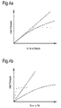
- Figures 4a and 4b show schematic graphs of inlet pressure against percentage fill and fill time respectively.
- the solid line on each graph shows a conventional fast infusion
- the dashed line shows a conventional slow infusion
- the dotted line shows what could be achieved through the present invention.
- the conventional fast fill system requires very high pressures towards the end of the fill process, with all the attendant disadvantages of very high pressure systems, as discussed above.
- the conventional slow fill system is less demanding of pressure, but substantially slower, increasing the unit cost of each item and placing a finite limit on the size of component that can be manufactured.
- the present invention has the potential to fill a mould cavity more quickly than the fast fill system, and use lower applied pressure than the slow fill system.
- a further advantage of the present invention is manifested in its effect on the individual fibres within the fibre tows.
- the effective permeability in the space between the individual fibres is different to, and considerably lower than that in the space between the tows.
- Figure 5 shows a cross-section through a partially resin infused tow 500, Figure 5a illustrating the filaments 502 and Figure 5b illustrating the resin boundary 504 between the infused filament region 506 and the dry filament region 508.
- a tow will contain of the order of a thousand filaments, all of which are quite closely packed and the number of fibres can range from tens of fibres per tow up to in excess of 50 thousand.
- the filament bundle would be virtually impenetrable. It is only as the tow cross-section changes that gaps between filaments open up, as individual filaments must distort around each other to accommodate changes in cross-sectional shape dictated by tow weaving. These gaps allow for the penetration of liquid matrix material. Thus, in order for matrix material to penetrate into the fibre tow, the tow must be made to flex and move. This flexing motion is provided by the present invention, as repeated contraction and opening of the mould cavity also flexes the preform held within it. Flexing the preform opens and closes the filaments within the tows, thus encouraging early and complete infusion of the tows.
- any trapped gases are also teased out into the main body of fluid and carried to the upper surface and thence more rapidly to the outlets. This reduces porosity both within the tows, and in the tow-resin boundaries.
- Applying the peristaltic flexing when applying a pre-injection (partial) vacuum can assist in reducing the quantity of trapped gas or moisture.
- the above described invention thus employs the principles of peristalsis to reduce the pressure gradient necessary for liquid composite moulding. In doing this, the peak pressures required are reduced, and larger component manufacture becomes more feasible.
- a control system including sensors and actuators can be employed to maximise the advantages afforded, particularly by achieving localised seeded cure. This introduces additional solid regions in the mould cavity, influences the flow, and can be used to fix critical fibres into position and improve finished product quality.
- the invention affords many advantages when compared with conventional apparatus and systems. These advantages can be largely categorised as: (i) reducing unit cost, (ii) improving finished component quality, (iii) reducing processing time, and (iv) reducing waste.
- the invention reduces cost through the reduction in pressure required to force matrix material into and through the mould.
- Lower operating pressures reduce tooling and energy costs.
- the finished parts spend less time in the tooling, reducing the necessary man and resource hours per finished component, and are of a higher or at least more predictable quality, reducing scrap losses.
- components can be redesigned to take advantage of the increased quality and predictability afforded by the invention, allowing lower weight, greater complexity of geometry and reduced post manufacture machining steps.
- control system can position the pistons or blocks to make small adjustments to the mould without the usual time and cost of cutting a new surface.
- abrasive fillers such as clay
- Finished product quality is improved owing to the reduction of pressure and flow effects on fibre alignment, reduced distortion, improved infiltration in difficult regions and particularly within the fibre tows, and reduced and/or more evenly distributed porosity.
- the early lock in of key fibres that can be achieved by localised seeded cure using the control system also provides considerable improvement in product quality.
- Processing time is reduced by filling the mould more quickly, and thanks to the more even fill and faster equalisation of pressure following closure of the inlet.
- Waste is reduced thanks to the extension of resin shelf life enabled by the control system. Also tooling can be made less durable or will last longer, and the process is more energy efficient.
- the present invention has been described with reference to a resin transfer moulding (RTM) type process. However, it will be appreciated that the invention can be applied to other processing systems, such as a closed mould pre-preg system for debaulking of the preform before exerting final mould pressure and temperature for curing. Employing the present invention decreases the risk of fibre wrinkling through fibre movement during the cure cycle.
- RTM resin transfer moulding
- thermoset resin processing with carbon and/or glass fibre performs is equally applicable to other fibre types including basalt, boron, metal, nano-fibres, natural fibres such as hemp, or special fibres including DyneemaTM.
- the invention is also applicable to other matrix materials such as metals or thermoplastics. The substantial differences in viscosity between these matrix materials could mean order of magnitude differences to the processing, but the principles and advantages afforded by the invention remain.
- One field of application for the invention is in the manufacture of composite components for aero-engines. Particular benefits may also be enjoyed in industries where larger components are required, such as airframe and wing manufacture for aerospace applications, wind farm turbine blade manufacture and other civil engineering applications.
Landscapes
- Engineering & Computer Science (AREA)
- Mechanical Engineering (AREA)
- Chemical & Material Sciences (AREA)
- Composite Materials (AREA)
- Physics & Mathematics (AREA)
- Fluid Mechanics (AREA)
- Moulding By Coating Moulds (AREA)
- Casting Or Compression Moulding Of Plastics Or The Like (AREA)
Abstract
Description
- The present invention relates to apparatus for forming a composite component, and to an associated method. The invention relates particularly to the forming of composite components using liquid moulding processes, such as resin transfer moulding (RTM).
- Components formed from composite materials are widely used across a range of industries, including in the aerospace and automotive sectors. Composite components comprise a network of reinforcing fibres held within a typically resinous matrix material, and may be formed using a variety of processes. Liquid moulding processes are widely used for the forming of composite components, and a typical liquid moulding process comprises the following steps:
- a) a fibre preform is inserted into the mould, to form the reinforcement element of the composite component;
- b) the mould is sealed;
- c) the matrix material, in its liquid state, is forced under pressure into the mould and flows through the fibre preform until it reaches an outflow; and
- d) solidification of the matrix material is induced to form the finished component.
- The fibre preform may for example be a stack of fibre laminates, or may be a 3D woven or stitched piece of fabric that is formed from the reinforcing fibres. The shape of the preform approximates the net shape of the finished component.
- Solidification of the matrix material may be induced by heating or cooling. In the case of thermoset polymer matrix materials, a chemical change is induced in the material by heating. For thermoplastic or metal matrix materials, solidification is induced by cooling.
-
Figure 1 shows a cross section through a typical composite component mould 2. The geometry of the mould cavity 4 is not representative of any specific component, but illustrates features commonly found in composite components for a range of applications. Thematrix material inlet 6 is illustrated on the left of the Figure and theoutflow 8 is on the right. The fibre preform is placed inside the mould cavity 4, closely conforming to the internal geometry of the mould cavity. - Thermoset matrix materials are of high viscosity, typically 100 times that of water. Thermoplastic matrix materials have a viscosity between 1000 and 1000000 times that of thermosets. Very high pressures are therefore required to force the matrix material though the mould cavity. High pressures at the material inlet generate a pressure gradient between the inlet and the outlet, which increases with the size of the mould; the greater the distance to be travelled by the matrix material, the larger the pressure gradient. A vacuum may be drawn at the outlet of the matrix material, to assist in drawing the material through the full volume of the mould cavity. In addition, multiple outflow locations may be provided, especially where the component geometry is complex, in order to ensure a good fill in all regions of the mould, and to minimise the distance over which the matrix material must travel.
- The path of the matrix material through the mould cavity is obstructed by the presence of the fibre preform. The preform is composed of fibre tows, which may be woven, stitched or assembled in any other appropriate manner. The tows are themselves composed of individual filaments of reinforcing material. The blocking action of the preform within the mould is a function of the fibre volume fraction within the mould, the weave or layup style of the preform, the complexity of the volume of the mould cavity, and the compliance of the mould tooling. The degree of obstruction caused by the preform in the mould is referred to as the permeability of the preform. The structure of the preform means that there are in fact two "effective permeabilities" in the preform: the permeability in the space between the tows, and the permeability in the space between the filaments inside the tows. In the time taken for the viscous matrix material to move through the mould cavity, full infusion inside the fibre tows may not be complete.
- In the finished component, it is desirable to maximise the fibre volume fraction in order to achieve favourable structural properties, but increasing the fibre volume fraction has the effect of reducing the permeability of the preform during forming of the component. In order to achieve a high fibre volume fraction, the fabric of the preform is crushed within the mould cavity, flattening the tows and greatly reducing the permeability of the preform. This reduced permeability means that an increased pressure gradient is required to force the matrix material through the mould cavity. In order to address the issue of fibre volume fraction, it is known to provide multiple mould settings, allowing matrix material injection to take place at a relatively low fibre volume fraction, after which the mould cavity is reduced, the tool faces being brought closer together and squeezing out excess matrix material. An overflow gutter may be provided around the edge of the mould to catch this excess material. Mechanical closing of the mould to increase the fibre volume fraction is resisted by the injected fluid and the reducing permeability of the preform, meaning this approach is only suitable if the matrix material doesn't have far to flow and the tooling is sufficiently rigid not to distort. A relatively porous sacrificial material may also be used as a wick, acting to draw the matrix material and distribute it throughout the preform during material infusion.
- Even with the application of variable mould settings, and others of the techniques described above, the fact remains that driving highly viscous fluids through relatively low permeability preforms requires the application of high pressure. High operating pressures mean high grade equipment; powerful compressors, thick pipes, stiff tooling and consequently greater energy consumption, all leading to higher unit cost for the components manufactured. For large components, a significant pressure drop between inlet and outlet is inevitable, meaning pressures at the outlet of the component mould may be lower, and less easily controlled. This has implications for component quality and durability in the outlet region, as high pressure is necessary for the suppression of void formation. Voids in the injected matrix material result in undesirable porosity in the finished component. Where it is impractical to increase pressure levels to address this, injection time must increase, again increasing unit cost. However, there is a finite limit to the length of time that the injection process can take, as discussed below.
- If a thermosetting matrix material is employed, increasing temperature in order to reduce viscosity and speed the injection process is only possible to a certain degree, as higher temperatures induce the onset of gelation and cure of the component. Cure is exothermic, so as soon as one region starts to gel, a surrounding neighbourhood also begins the process of gelation. Pressure gradients within the flowing material also induce local thermal changes, though the second law of thermodynamics, meaning that a variety of interacting effects must be managed. The ultimate result of these conflicting and interacting factors is that there is a practical limit to the length of time that the injection process can take before the onset of solidification, and this imposes a finite limit on the size of component that can be manufactured.
- High pressures within the mould cavity can also lead to disruption of the fibres within the preform. This disruption may take the form of fibre waviness, regions of higher or lower fibre concentration, or creases or folds or wrinkles forming in the preform during the infusion. Regions of higher or lower concentration are a particular concern in component designs having unidirectional fibre regions. Folds or creases or wrinkles are a particular issue in components including a "T" joint.
- The present invention seeks to address some or all of the above noted disadvantages of existing methods and apparatus for liquid moulding of composite components.
- According to the present invention, there is provided apparatus for forming a composite component, comprising: a deformable mould tool that at least partially defines a mould cavity; an interface layer formed on an external surface of the mould tool; and at least two peristaltic actuators, mounted to contact the interface layer and to generate a peristaltic pressure wave in the mould tool.
- The interface layer may be integrally formed with the mould tool. Alternatively, the interface layer may be a separate component and may be sealed to the mould tool, for example by adhesive or other mechanical means.
- The interface layer may be flexible and may function as a flexible caul, ensuring even pressure distribution over the tool. This allows for distortion of the mould tool under pressure, while at the same time preventing localised pressure spikes and protecting the tool from high contact stresses. The interface layer may be formed from flexible caul materials such as invar sheet, mosite (platinum cured silicone sheet) - both could have external stiffening with such as carbon patches, strips, or sheets. For a semi-rigid tool the caul plate could be sprung steel plate or directionally rolled steel plate. Alternately, or in addition, multiple layers may be used with a softer material, for example silicone, being used as an immediate interface with a stiffer material for example metal, ceramic or composite providing support. The stiffer material may be ribbed or other wise structured to provide controlled flexure.
- The peristaltic actuators may comprise rollers which may be mounted to roll across a surface of the interface layer, so generating the peristaltic pressure wave.
- The separation between the rollers may be variable, allowing for variation of the wave form.
- The peristaltic actuators may comprise pistons. The pistons may be mechanically attached to the interface layer, such that the pistons are operable to apply tensile or compressive force to the interface layer.
- The peristaltic actuators may comprise metallic blocks and associated heating elements, the blocks being mounted on a fixed, rigid backing layer.
- At least two of the blocks may be formed from materials having different thermal expansion coefficients. In this manner, the blocks may exhibit a "bimetallic effect" the differing thermal expansion applying varying pressure to the interface layer, thus generating a peristaltic pressure wave.
- It will be appreciated that the apparatus may comprise a plurality of actuators of any of the forms disclosed, arranged along the interface layer. The number of actuators may be selected according to the dimensions of the mould tool and the desired wavelength of the peristaltic pressure wave to be generated in the tool. It will be further appreciated that increasing the number of actuators increases the fineness of control that can be achieved in managing the applied pressure within the tool.
- The pressure wave does not have to be linear, as for instance in the case of centre of mould injection the wave may be circular emanating from the injection point.
- The deformable mould tool may comprise first and second opposed tool sections that cooperate to define the mould cavity, each tool section having an associated interface layer formed on an external surface thereof, and at least two associated peristaltic actuators mounted to contact the associated interface layer and to generate a peristaltic pressure wave in the tool section.
- In another embodiment, the apparatus may further comprise a rigid mould tool that is in opposed relation to the deformable mould tool and cooperates with the deformable mould tool to define the mould cavity.
- The apparatus may further comprise a control system, which may be arranged to control the action of the peristaltic actuators.
- The control system may further comprise sensing elements, operable to sense parameters representative of conditions within the mould tool and deliver the sensed parameters to a processing unit of the control unit.
- According to another aspect of the present invention, there is provided a method of forming a composite component using a mould tool that at least partially defines a mould cavity, comprising: placing reinforcing fibres into the mould cavity, forcing a matrix material into the mould cavity through the reinforcing fibres, and generating a peristaltic pressure wave within the mould tool during forcing of the matrix material into the mould cavity.
- The reinforcing fibres may be woven, stitched or otherwise assembled as a preform.
- The peristaltic pressure wave may be generated by at least one of rollers, pistons or bi-metallic structures.
- For a better understanding of the present invention, and to show more clearly how it may be carried into effect, reference will now be made, by way of example, to the following drawings, in which:-
-
Figure 1 is a sectional view of a mould embodying features known in the art; -
Figure 2 is a sectional view of apparatus according to the present invention; -
Figure 3 is a sectional view of another embodiment of apparatus according to the invention; -
Figures 4a and 4b are graphs of inlet pressure for a component mould against time to fill the mould and the % fill of the mould; and -
Figures 5a and 5b show two sectional views of a partially resin infused fibre tow. - The present invention recognises that viscous fluids are moved around biological systems by peristalsis. Movement of viscous fluids is effected by alternating contraction and relaxation of the walls of a vessel carrying the fluid. This contraction and relaxation is coordinated into a wave like pattern, ensuring one way motion of the fluid and reducing the effective length of the vessel over which a pressure differential is required to the characteristic wavelength of the peristaltic motion. The present invention employs the principals of peristalsis within apparatus and methods for forming a composite component in order to address at least some of the above noted disadvantages of existing systems.
- With reference to
Figure 2 , a first embodiment ofapparatus 200 for forming a composite component comprises adeformable mould tool 204 and a plurality of peristaltic actuators in the form ofrollers 206. Themould tool 204 comprises first andsecond tool sections mould cavity 212 between them. Thecavity 212 is operable to receive a fibre preform (not shown) and comprises afluid inlet 214 at a first orinlet end 216 and afluid outlet 218 at a second oroutlet end 220. First and second interface layers 222, 224 are formed on external surfaces of the opposing first andsecond tool sections tool sections flexible cauls tool sections tool sections - In the illustrated embodiment, the
apparatus 200 comprises fourrollers 206 divided into first and second pairs ofrollers rollers 226 contacts theinterface layer 222 of thefirst tool section 208, and the second pair ofrollers 228 contacts theinterface layer 224 of thesecond tool section 210. The first and second pairs ofrollers rollers 228 is offset from the first pair ofrollers 226 in the vertical direction, as seen inFigure 2 . Therollers 206 are mounted to apply pressure to theadjacent interface layer corresponding tool section inlet end 216 to theoutlet end 218. - In use, the
rollers 206 assist the infusion of matrix material into themould cavity 212. The action of therollers 206 as they are rolled along the interface layers 222, 224 is to cause distortion in thetool sections mould cavity 212 in certain regions, and opening up or expansion of themould cavity 212 in adjacent regions. The regions of contraction and expansion travel along the mould cavity from theinlet end 216 to theoutlet end 218 with the motion of therollers 206, forming a peristaltic pressure wave within the tooling. The effect of the contraction and expansion of themould cavity 212 is to move the viscous liquid of the matrix material from the squeezed regions into the more open regions immediately ahead in the direction of travel. As the fibre volume fraction in the more open regions is lower, the viscous liquid flows more readily into it from the contracted regions. As therollers 206 pass over the more open regions, these regions are then contracted, and the fibre volume fraction is increased, but excess liquid passes easily into the newly opening regions just ahead, where the fibre volume fraction is decreasing. - The role of the
flexible cauls rollers 206 is to ensure even pressure distribution over the tool sections. The flexibility of thecauls mould tool sections tool sections - Repeated passage of the
rollers 206 leads to an even distribution of matrix material throughout thecavity 212. Successive passes of therollers 206 may be at higher or lower normal applied force, such that the final configuration is close to equal pressure/internal stress distributed throughout thecavity 212. Under such conditions, thetool sections mould tool sections - The action of the
rollers 206 may also be combined with multi-step tooling closure, such that the overall fibre volume fraction is stepped up between passes of therollers 206. It will be appreciated that the apparatus may comprise more or less than the two pairs ofrollers Figure 2 . The number ofrollers 206 may be selected according to the size of themould tool 204 and the level of control and variation required in the generation of the peristaltic pressure wave. It will also be understood that the mould tool may comprise a single deformable tool section in opposed relation to a substantially rigid, non deformable tool section. In this instance, the peristaltic pressure wave may be generated in only one section of the mould tool, contracting and expanding themould cavity 212 along one side only of thecavity 212. - The embodiment of apparatus described above and illustrated in
Figure 2 is particularly suited to the formation of components where the outer tooling surfaces are substantially flat, or are of single curvature. -
Figure 3 illustrates two alternative embodiments of apparatus; the first embodiment is illustrated in the upper tool section of the Figure and the second embodiment is illustrated in the lower tool section of the Figure. The two alternative embodiments are illustrated in the same apparatus for compactness of presentation inFigure 3 , but are described separately below. It is envisaged that in practice, any apparatus would employ only a single embodiment of the invention. This embodiment may be employed in both tool sections of an apparatus, or in a single tool section placed in opposed relation to a rigid, undeformable tool section, as described above with respect to the first embodiment. - With reference to the upper half of
Figure 3 , and in accordance with a first alternative embodiment of the invention, anapparatus 300 for forming a composite component comprises adeformable mould tool 304 and a plurality of peristaltic actuators in the form ofpistons 306. Themould tool 304 comprises first andsecond tool sections 308, 310 (of which only theupper tool section 308 is shown), which cooperate to define amould cavity 312 between them. Thecavity 312 is operable to receive a fibre preform (not shown) and comprises a fluid inlet 314 at a first orinlet end 316 and a fluid outlet 318 at a second oroutlet end 320. The following description of theapparatus 300 is directed to theupper tool section 308 and associated components, but it will be appreciated that corresponding features and components may be found on the lower tool section 310 (not shown). - An
interface layer 322 is formed on the external surface of thefirst tool section 308. Theinterface layer 322 comprises a flexible caul having features and being attached in a manner as described above with respect to theflexible cauls - As illustrated in
Figure 3 , the plurality ofpistons 306 is arrayed across theflexible caul 322. When mechanically attached to thecaul 322, thepistons 306 can apply compressive or tensile loading to thecaul 322, and through thecaul 322 to the associatedtool section 308. Thepistons 306 apply discrete point loading, and thecaul 322 ensures that this pressure is more evenly distributed in thetool section 308. The tensile and compressive loading of thepistons 306 generates a peristaltic pressure wave in thetool section 308 similar to that created by therollers 206 in the first embodiment shown inFigure 2 . This pressure wave has the same effect of contracting and expanding themould cavity 312 and assisting the injection of viscous matrix material into and through thecavity 312 as is described above with respect to the first embodiment. - The
pistons 306 provide increased flexibility of application, when compared to therollers 206 of the first embodiment, and can be applied to tool surfaces of more complex curvature. The precise location of the individual pistons may be selected according to component geometry. This apparatus may therefore be used to beneficial effect in the formation of complex composite components, particularly where there are regions that are small and hard to fill, but where manufacturing quality is important and porosity and fibre distortion must be avoided. - With reference to the lower half of
Figure 3 , and in accordance with a second alternative embodiment of the invention, anapparatus 400 for forming a composite component comprises adeformable mould tool 404 and a plurality of peristaltic actuators in the form ofmetallic blocks 406 and associated heating elements. Themould tool 404 comprises first and second tool sections 408, 410 (of which only thelower section 410 is shown), which cooperate to define amould cavity 412 between them. Thecavity 412 is operable to receive a fibre preform (not shown) and comprises a fluid inlet 414 at a first orinlet end 416 and a fluid outlet 418 at a second oroutlet end 420. The following description of theapparatus 400 is directed to thelower tool section 410 and associated components, but it will be appreciated that corresponding features and components may be found on the upper tool section 408 (not shown). - An
interface layer 424 is formed on the external surface of thesecond tool section 410. Theinterface layer 424 comprises a flexible caul having features and being attached in a manner as described above with respect to theflexible cauls - As illustrated in
Figure 3 , themetallic blocks 406 are mounted between theflexible caul 424 and a fixedrigid backing layer 425. Eachindividual block 406 may have a dedicated heating element, or in a preferred embodiment, the heating elements for the individual blocks may comprise an adjacent region of theflexible caul 424 orbacking layer 425, heat being applied in a controlled manner to either or both of theflexible caul 424 and/orbacking layer 425. In the illustrated embodiment, themetallic blocks 406 comprise alternating blocks of two different materials, the materials having different coefficients of thermal expansion. However, it will be appreciated that the blocks may be arranged in configurations other than the illustrated alternating arrangement, and that more than two different materials may be used, providing a varying array of coefficients of thermal expansion. Theblocks 406 exhibit a bi-metallic effect on heating by theflexible caul 424 and/orbacking sheet 425. By changing the temperature in thecaul 424 and/orbacking sheet 425, the blocks can provide tensile or compressive loading in much the same way as thepistons 306, and can thus generate a peristaltic pressure wave in the tool section 310. This pressure wave has the same effect of contracting and expanding themould cavity 412 and assisting the injection of viscous matrix material into and through thecavity 412 as is described above with respect to the first embodiment. - As can be appreciated by the skilled user, pistons and thermionic blocks are just two ways of exerting pressures to form a peristaltic wave. Other actuators such as piezoelectric stacks, hydraulic pads, etc could be used in their place.
- Also illustrated in the lower part of
Figure 3 is acontrol system 450. Thecontrol system 450 will be described with reference to the second alternative embodiment ofapparatus 400, but it will be appreciated that a control system of the type described below may be incorporated with beneficial effect into any embodiments of the present invention, including those disclosed above. - The
control system 450 may be connected to all of the component parts of theapparatus 400, including thetool section 410, thecavity 412, themetallic blocks 406 and theflexible caul 424 and/orbacking layer 425. The control system preferably includessensing elements 452 and actuators operable to dictate behaviour of the peristaltic actuators of the apparatus. Thecontrol system 450 takes local measurements of liquid matrix material temperature, pressure and velocity. It may also take measurements of electrical capacitance, as the dielectric constant of the matrix material changes from the liquid state through gelation to the cured state. From these measurements, and comparison with theoretical, modelling or intelligent system interpretation, the state of viscosity and possible onset of gelation of the matrix material may be deduced. The control system then initiates appropriate action in the bi-metallic blocks 406 (or in therollers 206 or pistons 306) to manage the infusion and cure of the matrix material. - A primary advantage of the
control system 450 is in managing the effects of resin matrix material ageing. Aspects of the behaviour of a resin matrix material can change over the shelf life of the material, and these changes can lead to substantial variations in the pressure differential required to drive the liquid resin into the preform. Thecontrol system 450 provides real time information as to the behaviour of the matrix material, compensating for any behavioural changes owing to the age of the material. The system thus allows for a relaxation in acceptable shelf life limits for certain resin matrix materials, meaning that batch sizes can be increased without impacting upon finished component quality. Thesystem 450 can also manage the effects of other variations affecting the injection process. Manufacturing variables can induce slight differences in the preform shape and size. These differences are minor in themselves but can influence the local preform permeability and hence the flow of matrix material. Real time feedback and control through thecontrol system 450 can compensate for these minor variations, optimising infusion of the matrix material into and through the preform. - In addition to compensating for variations affecting resin inflow, the
control system 450 affords advantages in improving and ensuring finished component quality. The control system can be programmed to closely manage all stages of the infusion process at a local level. Thus, regions that are prone to fabric distortion can be targeted with low pressure liquid flow. This is achieved by the control system maintaining that region of the mould cavity as open as possible, and encouraging flow without over increasing the pressure differential. This region can then be squeezed down to final thickness again at low pressure differential. The localised flexibility of the piston arrays or bi-metallic blocks ofFigure 3 lend themselves well to this close control, allowing the application of specific pressure regimes to problem areas, while neighbouring regions continue to be subject to the contraction and expansion of the peristaltic wave motion. - The close control described above can even be used to induce early gelation in specific, problem prone areas, fixing the matrix material and fibres in place to avoid distortion while the rest of the cavity is filled. In order to achieve this localised seeded cure, thermal actuation is used to raise the temperature of the resin matrix material in a localised problem area to the gelation temperature. Cure then begins in this region, locking the fibres into position. Temperature controls remote from the region, together with thermal conduction through the preform fibres and thermal convection from the resin flow ensure that gelation does not spread, maintaining the gelation region finite until full infiltration of the preform is complete.
-
Figures 4a and 4b show schematic graphs of inlet pressure against percentage fill and fill time respectively. The solid line on each graph shows a conventional fast infusion, the dashed line shows a conventional slow infusion, and the dotted line shows what could be achieved through the present invention. - The conventional fast fill system requires very high pressures towards the end of the fill process, with all the attendant disadvantages of very high pressure systems, as discussed above. The conventional slow fill system is less demanding of pressure, but substantially slower, increasing the unit cost of each item and placing a finite limit on the size of component that can be manufactured. The present invention has the potential to fill a mould cavity more quickly than the fast fill system, and use lower applied pressure than the slow fill system.
- A further advantage of the present invention is manifested in its effect on the individual fibres within the fibre tows. As noted above, the effective permeability in the space between the individual fibres is different to, and considerably lower than that in the space between the tows.
Figure 5 shows a cross-section through a partially resin infusedtow 500,Figure 5a illustrating thefilaments 502 andFigure 5b illustrating theresin boundary 504 between the infusedfilament region 506 and thedry filament region 508. Typically a tow will contain of the order of a thousand filaments, all of which are quite closely packed and the number of fibres can range from tens of fibres per tow up to in excess of 50 thousand. There is usually a slight twist to the tow, which ensures that the filaments stay tightly packed to each other, particularly when they are in a woven fabric. Flattening the fabric down when the mould closes causes the filaments to move to new positions so that the overall tow shape becomes roughly elliptical or lenticular. In assuming this shape, the outermost filaments are placed under tensile or compressive loading, the loading changing with the cross sectional shape as the tow weaves between other tows. - For a perfectly aligned set of filaments within a tow, the filament bundle would be virtually impenetrable. It is only as the tow cross-section changes that gaps between filaments open up, as individual filaments must distort around each other to accommodate changes in cross-sectional shape dictated by tow weaving. These gaps allow for the penetration of liquid matrix material. Thus, in order for matrix material to penetrate into the fibre tow, the tow must be made to flex and move. This flexing motion is provided by the present invention, as repeated contraction and opening of the mould cavity also flexes the preform held within it. Flexing the preform opens and closes the filaments within the tows, thus encouraging early and complete infusion of the tows. As a consequence of this, any trapped gases are also teased out into the main body of fluid and carried to the upper surface and thence more rapidly to the outlets. This reduces porosity both within the tows, and in the tow-resin boundaries. Applying the peristaltic flexing when applying a pre-injection (partial) vacuum can assist in reducing the quantity of trapped gas or moisture.
- The above described invention thus employs the principles of peristalsis to reduce the pressure gradient necessary for liquid composite moulding. In doing this, the peak pressures required are reduced, and larger component manufacture becomes more feasible. As an additional feature, a control system including sensors and actuators can be employed to maximise the advantages afforded, particularly by achieving localised seeded cure. This introduces additional solid regions in the mould cavity, influences the flow, and can be used to fix critical fibres into position and improve finished product quality.
- The invention affords many advantages when compared with conventional apparatus and systems. These advantages can be largely categorised as: (i) reducing unit cost, (ii) improving finished component quality, (iii) reducing processing time, and (iv) reducing waste.
- The invention reduces cost through the reduction in pressure required to force matrix material into and through the mould. Lower operating pressures reduce tooling and energy costs. Additionally, the finished parts spend less time in the tooling, reducing the necessary man and resource hours per finished component, and are of a higher or at least more predictable quality, reducing scrap losses. Finally, components can be redesigned to take advantage of the increased quality and predictability afforded by the invention, allowing lower weight, greater complexity of geometry and reduced post manufacture machining steps.
- During the development phase, the control system can position the pistons or blocks to make small adjustments to the mould without the usual time and cost of cutting a new surface. Likewise if one part of the mould has a tendency to wear, such as when abrasive fillers (such as clay) are used in the matrix, this can be compensated for in a similar manner.
- Finished product quality is improved owing to the reduction of pressure and flow effects on fibre alignment, reduced distortion, improved infiltration in difficult regions and particularly within the fibre tows, and reduced and/or more evenly distributed porosity. The early lock in of key fibres that can be achieved by localised seeded cure using the control system also provides considerable improvement in product quality.
- Processing time is reduced by filling the mould more quickly, and thanks to the more even fill and faster equalisation of pressure following closure of the inlet.
- Waste is reduced thanks to the extension of resin shelf life enabled by the control system. Also tooling can be made less durable or will last longer, and the process is more energy efficient.
- The present invention has been described with reference to a resin transfer moulding (RTM) type process. However, it will be appreciated that the invention can be applied to other processing systems, such as a closed mould pre-preg system for debaulking of the preform before exerting final mould pressure and temperature for curing. Employing the present invention decreases the risk of fibre wrinkling through fibre movement during the cure cycle.
- A primary application for the invention is in thermoset resin processing with carbon and/or glass fibre performs. However, the invention is equally applicable to other fibre types including basalt, boron, metal, nano-fibres, natural fibres such as hemp, or special fibres including Dyneema™. The invention is also applicable to other matrix materials such as metals or thermoplastics. The substantial differences in viscosity between these matrix materials could mean order of magnitude differences to the processing, but the principles and advantages afforded by the invention remain.
- One field of application for the invention is in the manufacture of composite components for aero-engines. Particular benefits may also be enjoyed in industries where larger components are required, such as airframe and wing manufacture for aerospace applications, wind farm turbine blade manufacture and other civil engineering applications.
Claims (15)
- Apparatus (200) for forming a composite component, comprising: a deformable mould tool (204) that at least partially defines a mould cavity (212); an interface layer (222,224) provided between an external surface (208,210) of the mould tool (204) and at least two peristaltic actuators (226,228), mounted to contact the interface layer (222,224) and to generate a peristaltic pressure wave in the mould tool (204).
- Apparatus (200) as claimed in claim 1, wherein the interface layer (222,224) is formed on the mould tool (204).
- Apparatus (200) as claimed in claim 1, wherein the interface layer (222,224) is integrally formed with the mould tool (204).
- Apparatus (200) as claimed in claim 1, wherein the interface layer (222,224) is sealed to the mould tool (204).
- Apparatus (200) as claimed in any one of claims 1 to 4, wherein the peristaltic actuators (226,228) comprise rollers (206) mounted to roll across a surface of the interface layer (222,224).
- Apparatus (200) as claimed in claim 5, wherein the separation between the rollers (206) is variable.
- Apparatus (200) as claimed in any one of claims 1 to 4, wherein the peristaltic actuators (226,228) comprise pistons (306).
- Apparatus (200) as claimed in claim 7, wherein the pistons (306) are mechanically attached to the interface layer (222,224), such that the pistons (306) are operable to apply tensile or compressive force to the interface layer (222,224).
- Apparatus (200) as claimed in any one of claims 1 to 4, wherein the peristaltic actuators (226,228) comprise metallic blocks (406) and associated heating elements, the blocks (406) being mounted on a fixed, rigid backing layer.
- Apparatus (200) as claimed in claim 9 wherein at least two of the blocks (406) are formed from materials having different thermal expansion coefficients.
- Apparatus (200) as claimed in any one of the preceding claims, wherein the deformable mould tool (204) comprises first and second opposed tool sections that cooperate to define the mould cavity (212), each tool section having an associated interface layer (222,224) formed on an external surface thereof and at least two associated peristaltic actuators (226,228) mounted to contact the associated interface layer (222,224) and generate a peristaltic pressure wave in the tool section.
- Apparatus (200) as claimed in any one of the preceding claims, further comprising a control system, arranged to control the action of the peristaltic actuators (226,228).
- Apparatus (200) as claimed in claim 12, wherein the control system (450) further comprises sensing elements (452), operable to sense parameters representative of conditions within the mould tool (204) and deliver the sensed parameters to a processing unit of the control unit.
- A method of forming a composite component using a mould tool (204) that at least partially defines a mould cavity (212), comprising: placing reinforcing fibres into the mould cavity (212), forcing a matrix material into the mould cavity (212) through the reinforcing fibres, and generating a peristaltic pressure wave within the mould tool (204) during forcing of the matrix material into the mould cavity (212).
- A method as claimed in claim 14, wherein the peristaltic pressure wave is generated by at least one of rollers, pistons and bi-metallic structures.
Applications Claiming Priority (1)
| Application Number | Priority Date | Filing Date | Title |
|---|---|---|---|
| GBGB1102406.4A GB201102406D0 (en) | 2011-02-11 | 2011-02-11 | Apparatus for forming a composite component |
Publications (2)
| Publication Number | Publication Date |
|---|---|
| EP2487024A1 true EP2487024A1 (en) | 2012-08-15 |
| EP2487024B1 EP2487024B1 (en) | 2014-08-27 |
Family
ID=43859270
Family Applications (1)
| Application Number | Title | Priority Date | Filing Date |
|---|---|---|---|
| EP12151888.0A Not-in-force EP2487024B1 (en) | 2011-02-11 | 2012-01-20 | Apparatus and method for forming a composite component |
Country Status (3)
| Country | Link |
|---|---|
| US (1) | US9168686B2 (en) |
| EP (1) | EP2487024B1 (en) |
| GB (1) | GB201102406D0 (en) |
Cited By (5)
| Publication number | Priority date | Publication date | Assignee | Title |
|---|---|---|---|---|
| WO2014058561A1 (en) * | 2012-10-10 | 2014-04-17 | The Boeing Company | Shape-distorting tooling system and method for curing composite parts |
| EP2857168A1 (en) * | 2013-10-02 | 2015-04-08 | BAE Systems PLC | Flexible tooling |
| WO2015049509A1 (en) * | 2013-10-02 | 2015-04-09 | Bae Systems Plc | Flexible tooling |
| WO2022083882A1 (en) * | 2020-10-21 | 2022-04-28 | Neue Materialien Fürth GmbH | Press device and method for producing a pressed product |
| US12064365B2 (en) | 2017-07-03 | 2024-08-20 | Ossur Iceland Ehf | Structure comprising stackable layers |
Families Citing this family (1)
| Publication number | Priority date | Publication date | Assignee | Title |
|---|---|---|---|---|
| ES2539312B1 (en) * | 2013-11-29 | 2016-05-10 | Industrias Deltavigo S.L. | Automated manufacturing process of preforms of composite frames and stiffeners |
Citations (5)
| Publication number | Priority date | Publication date | Assignee | Title |
|---|---|---|---|---|
| GB944955A (en) * | 1960-04-12 | 1963-12-18 | English Electric Co Ltd | Improvements in or relating to methods of producing reinforced plastic structures |
| US5039371A (en) * | 1989-03-23 | 1991-08-13 | Lockheed Corporation | Apparatus for roll-consolidation of thermoplastic composite laminates |
| US5151277A (en) * | 1991-03-27 | 1992-09-29 | The Charles Stark Draper Lab., Inc. | Reconfigurable fiber-forming resin transfer system |
| US20030227107A1 (en) * | 1999-03-18 | 2003-12-11 | Stewart David H. | Method and machine for manufacturing molded structures using zoned pressure molding |
| EP2236271A1 (en) * | 2009-03-30 | 2010-10-06 | Eurocopter Deutschland GmbH | Method and mould tool for producing a component made of fibre-reinforced plastic |
Family Cites Families (3)
| Publication number | Priority date | Publication date | Assignee | Title |
|---|---|---|---|---|
| US5672227A (en) | 1995-12-18 | 1997-09-30 | Chiu; Chang-Hsuan | Resin transfer molding process for making composite pipe |
| US7249943B2 (en) * | 2003-08-01 | 2007-07-31 | Alliant Techsystems Inc. | Apparatus for forming composite stiffeners and reinforcing structures |
| US20080093776A1 (en) | 2006-10-05 | 2008-04-24 | 3M Innovative Properties Company | Method of molding ultraviolet cured microstructures and molds |
-
2011
- 2011-02-11 GB GBGB1102406.4A patent/GB201102406D0/en not_active Ceased
-
2012
- 2012-01-20 US US13/354,802 patent/US9168686B2/en active Active
- 2012-01-20 EP EP12151888.0A patent/EP2487024B1/en not_active Not-in-force
Patent Citations (5)
| Publication number | Priority date | Publication date | Assignee | Title |
|---|---|---|---|---|
| GB944955A (en) * | 1960-04-12 | 1963-12-18 | English Electric Co Ltd | Improvements in or relating to methods of producing reinforced plastic structures |
| US5039371A (en) * | 1989-03-23 | 1991-08-13 | Lockheed Corporation | Apparatus for roll-consolidation of thermoplastic composite laminates |
| US5151277A (en) * | 1991-03-27 | 1992-09-29 | The Charles Stark Draper Lab., Inc. | Reconfigurable fiber-forming resin transfer system |
| US20030227107A1 (en) * | 1999-03-18 | 2003-12-11 | Stewart David H. | Method and machine for manufacturing molded structures using zoned pressure molding |
| EP2236271A1 (en) * | 2009-03-30 | 2010-10-06 | Eurocopter Deutschland GmbH | Method and mould tool for producing a component made of fibre-reinforced plastic |
Cited By (6)
| Publication number | Priority date | Publication date | Assignee | Title |
|---|---|---|---|---|
| WO2014058561A1 (en) * | 2012-10-10 | 2014-04-17 | The Boeing Company | Shape-distorting tooling system and method for curing composite parts |
| US8986484B2 (en) | 2012-10-10 | 2015-03-24 | The Boeing Company | Shape-distorting tooling system and method for curing composite parts |
| EP2857168A1 (en) * | 2013-10-02 | 2015-04-08 | BAE Systems PLC | Flexible tooling |
| WO2015049509A1 (en) * | 2013-10-02 | 2015-04-09 | Bae Systems Plc | Flexible tooling |
| US12064365B2 (en) | 2017-07-03 | 2024-08-20 | Ossur Iceland Ehf | Structure comprising stackable layers |
| WO2022083882A1 (en) * | 2020-10-21 | 2022-04-28 | Neue Materialien Fürth GmbH | Press device and method for producing a pressed product |
Also Published As
| Publication number | Publication date |
|---|---|
| US20120205835A1 (en) | 2012-08-16 |
| US9168686B2 (en) | 2015-10-27 |
| EP2487024B1 (en) | 2014-08-27 |
| GB201102406D0 (en) | 2011-03-30 |
Similar Documents
| Publication | Publication Date | Title |
|---|---|---|
| US9168686B2 (en) | Apparatus for forming a composite component | |
| US11926093B2 (en) | Methods and apparatus for embedding heating circuits into articles made by additive manufacturing and articles made therefrom | |
| Michaud | A review of non-saturated resin flow in liquid composite moulding processes | |
| Studer et al. | Effect of fabric architecture, compaction and permeability on through thickness thermoplastic melt impregnation | |
| JP5634408B2 (en) | Constant pressure injection method for resin transfer molding | |
| Qi et al. | A resin film infusion process for manufacture of advanced composite structures | |
| US11072432B2 (en) | Method for manufacturing a part made of a composite material comprising at least one portion forming a force-insertion portion or local thickened portion | |
| Laurenzi et al. | Process simulation for a large composite aeronautic beam by resin transfer molding | |
| Kang et al. | Analysis of resin transfer moulding process with controlled multiple gates resin injection | |
| Gourichon et al. | A new numerical procedure to predict dynamic void content in liquid composite molding | |
| Harshe | A review on advanced out-of-autoclave composites processing | |
| CN114269548B (en) | Method and device for producing a component made of a fiber composite material | |
| Jespersen et al. | Film stacking impregnation model for a novel net shape thermoplastic composite preforming process | |
| WO2009044194A2 (en) | Method of moulding a charge | |
| US20130333793A1 (en) | Fibrous structure for a part made of a composite material and having a complex shape | |
| Quadrini et al. | Shape memory polymer composite unit with embedded heater | |
| Li et al. | Modeling and analysis of thickness gradient and variations in vacuum‐assisted resin transfer molding process | |
| Rudd et al. | Towards a manufacturing technology for high-volume production of composite components | |
| CN114599505B (en) | Method for producing a component from a fiber composite material | |
| EP3927527B1 (en) | Fabrication of three-dimensional structures from preform blanks | |
| WO2019012242A1 (en) | Composite lay-up apparatus and method | |
| Chamberlain et al. | Cost effective thermoplastic composites in aerostructures | |
| Goncharova et al. | Analytical modeling of composite manufacturing by vacuum assisted infusion with minimal experimental characterization of random fabrics | |
| KR102220747B1 (en) | Molding apparatus for composite material | |
| Zhang et al. | Overview of preparation methods for high performance composite materials |
Legal Events
| Date | Code | Title | Description |
|---|---|---|---|
| PUAI | Public reference made under article 153(3) epc to a published international application that has entered the european phase |
Free format text: ORIGINAL CODE: 0009012 |
|
| AK | Designated contracting states |
Kind code of ref document: A1 Designated state(s): AL AT BE BG CH CY CZ DE DK EE ES FI FR GB GR HR HU IE IS IT LI LT LU LV MC MK MT NL NO PL PT RO RS SE SI SK SM TR |
|
| AX | Request for extension of the european patent |
Extension state: BA ME |
|
| 17P | Request for examination filed |
Effective date: 20130207 |
|
| 17Q | First examination report despatched |
Effective date: 20130408 |
|
| GRAP | Despatch of communication of intention to grant a patent |
Free format text: ORIGINAL CODE: EPIDOSNIGR1 |
|
| INTG | Intention to grant announced |
Effective date: 20140520 |
|
| INTG | Intention to grant announced |
Effective date: 20140527 |
|
| GRAP | Despatch of communication of intention to grant a patent |
Free format text: ORIGINAL CODE: EPIDOSNIGR1 |
|
| GRAS | Grant fee paid |
Free format text: ORIGINAL CODE: EPIDOSNIGR3 |
|
| GRAA | (expected) grant |
Free format text: ORIGINAL CODE: 0009210 |
|
| INTG | Intention to grant announced |
Effective date: 20140704 |
|
| AK | Designated contracting states |
Kind code of ref document: B1 Designated state(s): AL AT BE BG CH CY CZ DE DK EE ES FI FR GB GR HR HU IE IS IT LI LT LU LV MC MK MT NL NO PL PT RO RS SE SI SK SM TR |
|
| REG | Reference to a national code |
Ref country code: GB Ref legal event code: FG4D |
|
| REG | Reference to a national code |
Ref country code: CH Ref legal event code: EP |
|
| REG | Reference to a national code |
Ref country code: AT Ref legal event code: REF Ref document number: 684288 Country of ref document: AT Kind code of ref document: T Effective date: 20140915 |
|
| REG | Reference to a national code |
Ref country code: IE Ref legal event code: FG4D |
|
| REG | Reference to a national code |
Ref country code: DE Ref legal event code: R096 Ref document number: 602012002844 Country of ref document: DE Effective date: 20141009 |
|
| REG | Reference to a national code |
Ref country code: AT Ref legal event code: MK05 Ref document number: 684288 Country of ref document: AT Kind code of ref document: T Effective date: 20140827 |
|
| REG | Reference to a national code |
Ref country code: LT Ref legal event code: MG4D |
|
| REG | Reference to a national code |
Ref country code: NL Ref legal event code: VDEP Effective date: 20140827 |
|
| PG25 | Lapsed in a contracting state [announced via postgrant information from national office to epo] |
Ref country code: NO Free format text: LAPSE BECAUSE OF FAILURE TO SUBMIT A TRANSLATION OF THE DESCRIPTION OR TO PAY THE FEE WITHIN THE PRESCRIBED TIME-LIMIT Effective date: 20141127 Ref country code: LT Free format text: LAPSE BECAUSE OF FAILURE TO SUBMIT A TRANSLATION OF THE DESCRIPTION OR TO PAY THE FEE WITHIN THE PRESCRIBED TIME-LIMIT Effective date: 20140827 Ref country code: BG Free format text: LAPSE BECAUSE OF FAILURE TO SUBMIT A TRANSLATION OF THE DESCRIPTION OR TO PAY THE FEE WITHIN THE PRESCRIBED TIME-LIMIT Effective date: 20141127 Ref country code: ES Free format text: LAPSE BECAUSE OF FAILURE TO SUBMIT A TRANSLATION OF THE DESCRIPTION OR TO PAY THE FEE WITHIN THE PRESCRIBED TIME-LIMIT Effective date: 20140827 Ref country code: FI Free format text: LAPSE BECAUSE OF FAILURE TO SUBMIT A TRANSLATION OF THE DESCRIPTION OR TO PAY THE FEE WITHIN THE PRESCRIBED TIME-LIMIT Effective date: 20140827 Ref country code: SE Free format text: LAPSE BECAUSE OF FAILURE TO SUBMIT A TRANSLATION OF THE DESCRIPTION OR TO PAY THE FEE WITHIN THE PRESCRIBED TIME-LIMIT Effective date: 20140827 Ref country code: PT Free format text: LAPSE BECAUSE OF FAILURE TO SUBMIT A TRANSLATION OF THE DESCRIPTION OR TO PAY THE FEE WITHIN THE PRESCRIBED TIME-LIMIT Effective date: 20141229 Ref country code: GR Free format text: LAPSE BECAUSE OF FAILURE TO SUBMIT A TRANSLATION OF THE DESCRIPTION OR TO PAY THE FEE WITHIN THE PRESCRIBED TIME-LIMIT Effective date: 20141128 |
|
| PG25 | Lapsed in a contracting state [announced via postgrant information from national office to epo] |
Ref country code: IS Free format text: LAPSE BECAUSE OF FAILURE TO SUBMIT A TRANSLATION OF THE DESCRIPTION OR TO PAY THE FEE WITHIN THE PRESCRIBED TIME-LIMIT Effective date: 20141227 Ref country code: CY Free format text: LAPSE BECAUSE OF FAILURE TO SUBMIT A TRANSLATION OF THE DESCRIPTION OR TO PAY THE FEE WITHIN THE PRESCRIBED TIME-LIMIT Effective date: 20140827 Ref country code: LV Free format text: LAPSE BECAUSE OF FAILURE TO SUBMIT A TRANSLATION OF THE DESCRIPTION OR TO PAY THE FEE WITHIN THE PRESCRIBED TIME-LIMIT Effective date: 20140827 Ref country code: RS Free format text: LAPSE BECAUSE OF FAILURE TO SUBMIT A TRANSLATION OF THE DESCRIPTION OR TO PAY THE FEE WITHIN THE PRESCRIBED TIME-LIMIT Effective date: 20140827 Ref country code: AT Free format text: LAPSE BECAUSE OF FAILURE TO SUBMIT A TRANSLATION OF THE DESCRIPTION OR TO PAY THE FEE WITHIN THE PRESCRIBED TIME-LIMIT Effective date: 20140827 Ref country code: HR Free format text: LAPSE BECAUSE OF FAILURE TO SUBMIT A TRANSLATION OF THE DESCRIPTION OR TO PAY THE FEE WITHIN THE PRESCRIBED TIME-LIMIT Effective date: 20140827 |
|
| PG25 | Lapsed in a contracting state [announced via postgrant information from national office to epo] |
Ref country code: NL Free format text: LAPSE BECAUSE OF FAILURE TO SUBMIT A TRANSLATION OF THE DESCRIPTION OR TO PAY THE FEE WITHIN THE PRESCRIBED TIME-LIMIT Effective date: 20140827 |
|
| PG25 | Lapsed in a contracting state [announced via postgrant information from national office to epo] |
Ref country code: IT Free format text: LAPSE BECAUSE OF FAILURE TO SUBMIT A TRANSLATION OF THE DESCRIPTION OR TO PAY THE FEE WITHIN THE PRESCRIBED TIME-LIMIT Effective date: 20140827 Ref country code: EE Free format text: LAPSE BECAUSE OF FAILURE TO SUBMIT A TRANSLATION OF THE DESCRIPTION OR TO PAY THE FEE WITHIN THE PRESCRIBED TIME-LIMIT Effective date: 20140827 Ref country code: DK Free format text: LAPSE BECAUSE OF FAILURE TO SUBMIT A TRANSLATION OF THE DESCRIPTION OR TO PAY THE FEE WITHIN THE PRESCRIBED TIME-LIMIT Effective date: 20140827 Ref country code: CZ Free format text: LAPSE BECAUSE OF FAILURE TO SUBMIT A TRANSLATION OF THE DESCRIPTION OR TO PAY THE FEE WITHIN THE PRESCRIBED TIME-LIMIT Effective date: 20140827 Ref country code: RO Free format text: LAPSE BECAUSE OF FAILURE TO SUBMIT A TRANSLATION OF THE DESCRIPTION OR TO PAY THE FEE WITHIN THE PRESCRIBED TIME-LIMIT Effective date: 20140827 Ref country code: SK Free format text: LAPSE BECAUSE OF FAILURE TO SUBMIT A TRANSLATION OF THE DESCRIPTION OR TO PAY THE FEE WITHIN THE PRESCRIBED TIME-LIMIT Effective date: 20140827 |
|
| REG | Reference to a national code |
Ref country code: DE Ref legal event code: R097 Ref document number: 602012002844 Country of ref document: DE |
|
| PG25 | Lapsed in a contracting state [announced via postgrant information from national office to epo] |
Ref country code: PL Free format text: LAPSE BECAUSE OF FAILURE TO SUBMIT A TRANSLATION OF THE DESCRIPTION OR TO PAY THE FEE WITHIN THE PRESCRIBED TIME-LIMIT Effective date: 20140827 |
|
| PG25 | Lapsed in a contracting state [announced via postgrant information from national office to epo] |
Ref country code: BE Free format text: LAPSE BECAUSE OF NON-PAYMENT OF DUE FEES Effective date: 20150131 |
|
| PLBE | No opposition filed within time limit |
Free format text: ORIGINAL CODE: 0009261 |
|
| STAA | Information on the status of an ep patent application or granted ep patent |
Free format text: STATUS: NO OPPOSITION FILED WITHIN TIME LIMIT |
|
| RAP2 | Party data changed (patent owner data changed or rights of a patent transferred) |
Owner name: ROLLS-ROYCE PLC |
|
| 26N | No opposition filed |
Effective date: 20150528 |
|
| REG | Reference to a national code |
Ref country code: CH Ref legal event code: PL |
|
| PG25 | Lapsed in a contracting state [announced via postgrant information from national office to epo] |
Ref country code: LU Free format text: LAPSE BECAUSE OF FAILURE TO SUBMIT A TRANSLATION OF THE DESCRIPTION OR TO PAY THE FEE WITHIN THE PRESCRIBED TIME-LIMIT Effective date: 20150120 |
|
| PG25 | Lapsed in a contracting state [announced via postgrant information from national office to epo] |
Ref country code: MC Free format text: LAPSE BECAUSE OF FAILURE TO SUBMIT A TRANSLATION OF THE DESCRIPTION OR TO PAY THE FEE WITHIN THE PRESCRIBED TIME-LIMIT Effective date: 20140827 |
|
| PG25 | Lapsed in a contracting state [announced via postgrant information from national office to epo] |
Ref country code: LI Free format text: LAPSE BECAUSE OF NON-PAYMENT OF DUE FEES Effective date: 20150131 Ref country code: CH Free format text: LAPSE BECAUSE OF NON-PAYMENT OF DUE FEES Effective date: 20150131 |
|
| REG | Reference to a national code |
Ref country code: IE Ref legal event code: MM4A |
|
| PG25 | Lapsed in a contracting state [announced via postgrant information from national office to epo] |
Ref country code: SI Free format text: LAPSE BECAUSE OF FAILURE TO SUBMIT A TRANSLATION OF THE DESCRIPTION OR TO PAY THE FEE WITHIN THE PRESCRIBED TIME-LIMIT Effective date: 20140827 |
|
| REG | Reference to a national code |
Ref country code: FR Ref legal event code: PLFP Year of fee payment: 5 |
|
| PG25 | Lapsed in a contracting state [announced via postgrant information from national office to epo] |
Ref country code: IE Free format text: LAPSE BECAUSE OF NON-PAYMENT OF DUE FEES Effective date: 20150120 |
|
| PG25 | Lapsed in a contracting state [announced via postgrant information from national office to epo] |
Ref country code: BE Free format text: LAPSE BECAUSE OF FAILURE TO SUBMIT A TRANSLATION OF THE DESCRIPTION OR TO PAY THE FEE WITHIN THE PRESCRIBED TIME-LIMIT Effective date: 20140827 |
|
| PG25 | Lapsed in a contracting state [announced via postgrant information from national office to epo] |
Ref country code: MT Free format text: LAPSE BECAUSE OF FAILURE TO SUBMIT A TRANSLATION OF THE DESCRIPTION OR TO PAY THE FEE WITHIN THE PRESCRIBED TIME-LIMIT Effective date: 20140827 |
|
| REG | Reference to a national code |
Ref country code: FR Ref legal event code: PLFP Year of fee payment: 6 |
|
| PG25 | Lapsed in a contracting state [announced via postgrant information from national office to epo] |
Ref country code: HU Free format text: LAPSE BECAUSE OF FAILURE TO SUBMIT A TRANSLATION OF THE DESCRIPTION OR TO PAY THE FEE WITHIN THE PRESCRIBED TIME-LIMIT; INVALID AB INITIO Effective date: 20120120 Ref country code: SM Free format text: LAPSE BECAUSE OF FAILURE TO SUBMIT A TRANSLATION OF THE DESCRIPTION OR TO PAY THE FEE WITHIN THE PRESCRIBED TIME-LIMIT Effective date: 20140827 |
|
| PG25 | Lapsed in a contracting state [announced via postgrant information from national office to epo] |
Ref country code: TR Free format text: LAPSE BECAUSE OF FAILURE TO SUBMIT A TRANSLATION OF THE DESCRIPTION OR TO PAY THE FEE WITHIN THE PRESCRIBED TIME-LIMIT Effective date: 20140827 |
|
| REG | Reference to a national code |
Ref country code: FR Ref legal event code: PLFP Year of fee payment: 7 |
|
| PG25 | Lapsed in a contracting state [announced via postgrant information from national office to epo] |
Ref country code: MK Free format text: LAPSE BECAUSE OF FAILURE TO SUBMIT A TRANSLATION OF THE DESCRIPTION OR TO PAY THE FEE WITHIN THE PRESCRIBED TIME-LIMIT Effective date: 20140827 |
|
| PG25 | Lapsed in a contracting state [announced via postgrant information from national office to epo] |
Ref country code: AL Free format text: LAPSE BECAUSE OF FAILURE TO SUBMIT A TRANSLATION OF THE DESCRIPTION OR TO PAY THE FEE WITHIN THE PRESCRIBED TIME-LIMIT Effective date: 20140827 |
|
| PGFP | Annual fee paid to national office [announced via postgrant information from national office to epo] |
Ref country code: FR Payment date: 20230124 Year of fee payment: 12 |
|
| PGFP | Annual fee paid to national office [announced via postgrant information from national office to epo] |
Ref country code: GB Payment date: 20230124 Year of fee payment: 12 Ref country code: DE Payment date: 20230127 Year of fee payment: 12 |
|
| P01 | Opt-out of the competence of the unified patent court (upc) registered |
Effective date: 20230528 |
|
| REG | Reference to a national code |
Ref country code: DE Ref legal event code: R119 Ref document number: 602012002844 Country of ref document: DE |
|
| GBPC | Gb: european patent ceased through non-payment of renewal fee |
Effective date: 20240120 |
|
| PG25 | Lapsed in a contracting state [announced via postgrant information from national office to epo] |
Ref country code: DE Free format text: LAPSE BECAUSE OF NON-PAYMENT OF DUE FEES Effective date: 20240801 |
|
| PG25 | Lapsed in a contracting state [announced via postgrant information from national office to epo] |
Ref country code: GB Free format text: LAPSE BECAUSE OF NON-PAYMENT OF DUE FEES Effective date: 20240120 |
|
| PG25 | Lapsed in a contracting state [announced via postgrant information from national office to epo] |
Ref country code: FR Free format text: LAPSE BECAUSE OF NON-PAYMENT OF DUE FEES Effective date: 20240131 |
|
| PG25 | Lapsed in a contracting state [announced via postgrant information from national office to epo] |
Ref country code: GB Free format text: LAPSE BECAUSE OF NON-PAYMENT OF DUE FEES Effective date: 20240120 Ref country code: FR Free format text: LAPSE BECAUSE OF NON-PAYMENT OF DUE FEES Effective date: 20240131 Ref country code: DE Free format text: LAPSE BECAUSE OF NON-PAYMENT OF DUE FEES Effective date: 20240801 |