EP2486465B1 - An optical measurement instrument - Google Patents
An optical measurement instrument Download PDFInfo
- Publication number
- EP2486465B1 EP2486465B1 EP10776758.4A EP10776758A EP2486465B1 EP 2486465 B1 EP2486465 B1 EP 2486465B1 EP 10776758 A EP10776758 A EP 10776758A EP 2486465 B1 EP2486465 B1 EP 2486465B1
- Authority
- EP
- European Patent Office
- Prior art keywords
- heating resistors
- temperature
- measurement chamber
- base module
- plate
- Prior art date
- Legal status (The legal status is an assumption and is not a legal conclusion. Google has not performed a legal analysis and makes no representation as to the accuracy of the status listed.)
- Active
Links
Images


Classifications
-
- G—PHYSICS
- G01—MEASURING; TESTING
- G01N—INVESTIGATING OR ANALYSING MATERIALS BY DETERMINING THEIR CHEMICAL OR PHYSICAL PROPERTIES
- G01N21/00—Investigating or analysing materials by the use of optical means, i.e. using sub-millimetre waves, infrared, visible or ultraviolet light
- G01N21/62—Systems in which the material investigated is excited whereby it emits light or causes a change in wavelength of the incident light
- G01N21/63—Systems in which the material investigated is excited whereby it emits light or causes a change in wavelength of the incident light optically excited
- G01N21/64—Fluorescence; Phosphorescence
- G01N21/645—Specially adapted constructive features of fluorimeters
- G01N21/6452—Individual samples arranged in a regular 2D-array, e.g. multiwell plates
-
- G—PHYSICS
- G05—CONTROLLING; REGULATING
- G05D—SYSTEMS FOR CONTROLLING OR REGULATING NON-ELECTRIC VARIABLES
- G05D23/00—Control of temperature
- G05D23/19—Control of temperature characterised by the use of electric means
- G05D23/1917—Control of temperature characterised by the use of electric means using digital means
-
- G—PHYSICS
- G05—CONTROLLING; REGULATING
- G05D—SYSTEMS FOR CONTROLLING OR REGULATING NON-ELECTRIC VARIABLES
- G05D23/00—Control of temperature
- G05D23/19—Control of temperature characterised by the use of electric means
- G05D23/1919—Control of temperature characterised by the use of electric means characterised by the type of controller
-
- G—PHYSICS
- G05—CONTROLLING; REGULATING
- G05D—SYSTEMS FOR CONTROLLING OR REGULATING NON-ELECTRIC VARIABLES
- G05D23/00—Control of temperature
- G05D23/19—Control of temperature characterised by the use of electric means
- G05D23/1927—Control of temperature characterised by the use of electric means using a plurality of sensors
- G05D23/193—Control of temperature characterised by the use of electric means using a plurality of sensors sensing the temperaure in different places in thermal relationship with one or more spaces
- G05D23/1931—Control of temperature characterised by the use of electric means using a plurality of sensors sensing the temperaure in different places in thermal relationship with one or more spaces to control the temperature of one space
-
- G—PHYSICS
- G01—MEASURING; TESTING
- G01N—INVESTIGATING OR ANALYSING MATERIALS BY DETERMINING THEIR CHEMICAL OR PHYSICAL PROPERTIES
- G01N21/00—Investigating or analysing materials by the use of optical means, i.e. using sub-millimetre waves, infrared, visible or ultraviolet light
- G01N21/01—Arrangements or apparatus for facilitating the optical investigation
- G01N21/03—Cuvette constructions
- G01N21/0332—Cuvette constructions with temperature control
-
- G—PHYSICS
- G01—MEASURING; TESTING
- G01N—INVESTIGATING OR ANALYSING MATERIALS BY DETERMINING THEIR CHEMICAL OR PHYSICAL PROPERTIES
- G01N2201/00—Features of devices classified in G01N21/00
- G01N2201/02—Mechanical
- G01N2201/023—Controlling conditions in casing
- G01N2201/0231—Thermostating
Definitions
- the invention relates to a method for controlling temperature of samples being measured with an optical measurement instrument. Furthermore, the invention relates to a base module for an optical measurement instrument.
- the base module can be used as a platform with the aid of which different optical measurement instruments provided with measurement temperature control can be constructed using different optical measurement elements such as for example lenses, fibres, detectors, light sources, etc.
- An optical measurement can be, for example but not necessarily, an absorption measurement, a photoluminescence measurement, or a chemiluminescence measurement.
- the invention relates to an optical measurement instrument.
- Typical labels used are different radioactive isotopes, enzymes, different fluorescent molecules and e.g. fluorescent chelates of rare earth metals.
- Detection of enzyme labels can be performed by utilizing its natural biochemical function, i.e. to alter the physical properties of molecules.
- colourless substances are catalysed by enzyme to sparkle substances or non-fluorescent substances to fluorescent substances.
- the sparkling substances can be measured with absorption measurement, i.e. photometric measurement.
- absorption measurement the intensity of filtered and stabilized beam is first measured without any sample and then the sample inside one plate is measured. The absorbance i.e. the absorption values are then calculated.
- the fluorescent substances can be measured with fluorescent measurement that is generally used for measuring quantities of fluorescent label substance in a sample.
- the most photoluminescence labels are based on molecular photoluminescence process. In this process optical radiation is absorbed by the ground state of a molecule. Due to the absorption of energy the quantum molecule rises into higher excited state. After the fast vibrational relaxation the molecule returns back to its ground state and the excess energy is released as an optical quantum. Due to losses in this process the average absorbed energies are higher than the average emitted energies.
- a further measurement method is chemiluminescence measurement where emission of a substance is measured from a sample without excitation by illumination. Thus a photoluminometer suitable for photoluminescence measurements can also be used as a chemiluminometer.
- AlphaScreenTM Amplified Luminescent Proximity Homogeneous Assay
- the function of the AlphaScreenTM method is based on the use of small beads that attach to the molecules under study.
- beads There are two types of beads that are coated with a material acting either as a donor or acceptor of singlet-state oxygen. The measurement starts, when the liquid sample is illuminated by light with a suitable wavelength e.g. 680 nm. After this, the material in the donor bead converts ambient oxygen into singlet-state oxygen.
- the single-state molecules have a short lifetime and they can reach only about a 200 nm distance by diffusion in the liquid.
- both the donor and acceptor beads are bound to the same molecule and so they are sufficiently close to each other.
- the singlet-state oxygen may reach the acceptor bead where a series of reactions is started.
- the coating material in the acceptor beads emits photons in the 500-700 nm range. If the chemical reaction has not taken place the singlet-state oxygen cannot reach the acceptor bead and the emission light is not detected. By measuring the intensity of light it is possible to conclude the efficiency of the chemical reaction.
- An optical measurement instrument suitable for performing some or all of the measurements of the kind described above comprises typically at least one excitation light source for producing excitation beams to one or more samples to be measured at each time.
- Each excitation light source can be for example a flash lamp or a laser source.
- An optical path from an excitation light source to a sample may contain for example lenses, fibers, mirrors, dichroic mirrors, optical filters, monochromators and/or other optical elements.
- the optical measurement instrument further comprises at least one detector for detecting emission beams emitted by the samples to be measured at each time, and for producing detection signals responsive to the detected emission beams.
- Each detector can be for example a photo-diode or a photo-multiplier tube.
- An optical path from the sample to the detector may contain for example lenses, fibers, mirrors, dichroic mirrors, optical filters, monochromators, and/or other optical elements.
- the optical measurement instrument may further comprise a processing device for producing a measurement result for each sample to be measured on the basis of the detection signal related to that sample.
- the optical measurement instrument comprises a reception device for receiving samples to be measured.
- Each sample to be measured is stored in one of a plurality of sample wells that are built on e.g. a microtitration plate or some other sample support element.
- the reception device can be, for example, a movable sledge adapted to receive the microtitration plate or the other sample support element. Due to the fact that the reception device allows moving the microtitration plate or the other sample support element, the samples can be measured in a temporally successive manner so that each sample is in turn the sample that is currently being measured. In order to maximize quality of the measurement results obtained with the optical measurements, temperature of the samples being measured is tried to be kept as close as possible to an optimum measurement temperature.
- Publication US6977722 discloses an optical measurement instrument that includes an enclosure that is arranged to surround a reception device for receiving samples to be measured.
- the enclosure constitutes a measurement chamber arranged to protect the samples to be measured against undesired stray light and thermal radiation from the surroundings, and thus, inter alia, to keep the samples at a relatively steady temperature.
- An inconvenience related to the construction described above is that the temperature in the measurement chamber may, however, slowly wander along with changes of the temperature of the surroundings.
- optical measurement instrument comprises:
- the measurement chamber can be more easily kept at a desired temperature than in conjunction with the optical measurement instrument according to the prior art described earlier in this document.
- Value of each balancing coefficient depends on temperature/power-characteristics related to surroundings of the respective heating resistor. With the aid of the balancing coefficients, it is possible to achieve a desired temperature distribution (e.g. a flat temperature distribution) in a measurement chamber also in case where the temperature is measured only from a single spot. Values of the balancing coefficient may be different for different temperatures and/or temperature distributions. Hence, a desired temperature distribution can be achieved without a need for multiple measurements and multivariable control systems where the power sharing between heating resistors has to be determined on-line during operation of a measurement instrument.
- a new base module for an optical measurement instrument can be used as a platform with the aid of which different optical measurement instruments provided with measurement temperature control can be constructed using different optical measurement elements such as for example lenses, fibres, detectors, light sources, etc.
- the base module according to the invention comprises:
- the base module may preferably but not necessarily further comprise a controller arranged to control electrical power supplied to each of the at least one heating resistor on the basis of the temperature signal.
- a new method for controlling temperature of samples being measured with an optical measurement instrument comprises:
- FIG. 1 a shows a schematic illustration of a side view of an optical measurement instrument according to an embodiment of the invention.
- the optical measurement instrument includes a base module 100 that includes a mechanical structure that forms a measurement chamber 170 and acts as a support onto which one or more optical measurement elements can be mounted.
- the mechanical structure forming the measurement chamber 170 includes a first plate 102 and a second plate 103 that is substantially parallel and, in a direction perpendicular to the first plate, overlapping with the first plate.
- the second plate 103 is movably supported with respect to the first plate 102 so that the second plate is movable in the direction substantially perpendicular to the first and second plates, i.e. the second plate is moveable in the positive and negative z-directions of the co-ordinate system 190.
- the second plate 103 is movably supported to the first plate 102 with threaded rods and with respective counterparts.
- Reference numbers 111 and 112 indicate one of the threaded rods and its respective counterpart, respectively. It is also possible to support the second plate 103 movably with respect to the first plate 102 e.g. with the aid of toothed bars and respective gearwheels as counterparts of the toothed bars.
- the counterparts can be provided, for example, with servomotors arranged to move the second plate 103 in the positive or negative z-direction.
- the mechanical structure forming the measurement chamber further includes walls 104 extending from outer edges of the first plate to outer edges of the second plate.
- the said walls include a flexible portion 105 fastened to outer edges of the second plate 103.
- the flexible portion 105 allows the movement of the second plate relative to the first plate. It would be also possible to provide the second plate 103 e.g. with walls protruding towards the negative z-direction, overlapping the walls 104, and being capable of sliding with respect to the walls 104 thus allowing the movement of the second plate relative to the first plate.
- the optical measurement instrument includes, inside the measurement chamber 170, a reception device 101 for receiving samples 151, 152, 153, 154, 155, 156, 157 to be measured.
- the measurement chamber 170 is capable of protecting the samples against adverse stray light and thermal radiation from the surroundings.
- the walls 104 include a door element 106 for enabling insertion of the samples to be measured into the measurement chamber.
- the second plate 103 includes a fastening interface 107 provided with an aperture.
- the fastening interface is suitable for an optical measurement element 117 that is mounted to the second plate 103.
- the distance between the optical measurement element 117 and the sample being measured can be adjusted by moving the second plate 103 in the positive or negative z-direction.
- the first plate 102 includes a fastening interface 180 provided with an aperture and suitable for an optical measurement element. In the configuration shown in figure 1a , there is however no optical measurement element mounted to the fastening interface 180.
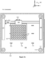
- FIG. 1b shows a schematic illustration of a view seen downwards from line A-A of figure 1a .
- the sample wells constitute in this exemplifying case a 7 x 7 array. In many cases there are, however, more sample wells in the array, e.g. 96 sample wells.
- the reception device 101 has an interface for receiving a changeable separate element 110, e.g. a microtitration plate, which includes the plurality of the sample wells.
- the reception device 101 is often called a sample plate sledge.
- the reception device 101 is mechanically connected to a support rail 140 that is supported by support elements 140' in such a manner that the support rail 140 is movable in the directions defined by a two-headed arrow 141 shown in figure 1 b.
- the reception device 101 is in turn movable along the support rail 140 in the directions defined by a two-headed arrow 142 shown in figure 1 b.
- the reception device 101 and thus also the sample wells are movable in parallel with the first and second plates 102 and 103, i.e. the reception device 101 and the sample wells are movable in the xy-plane defined by the co-ordinate system 190.
- each sample can be measured in its turn by changing the mechanical position of the reception device 101.
- a sample that is currently being measured is the sample 153 that is stored in the sample well 163.
- the element 110 including the sample wells is an integral part of the reception device, i.e. the reception device would include the sample wells, but several advantages are provided by having a changeable element that includes the plurality of sample wells.
- the optical measurement instrument includes an excitation light source 120 that is arranged to produce an excitation light beam.
- the excitation light source 120 can be, for example, a flash lamp.
- the excitation light beam radiated by the excitation light source 120 is collimated with a lens 121 and directed through an optical filter 122. Different optical filters can be selected for different wavelengths.
- the excitation light beam is then focused with a lens 123 to an end of a fibre optic guide 124, which guides the excitation light beam to the optical measurement element 117.
- the fibre optic guide can be, for example, a bundle of fibres, such as 200 pieces of fibres with a diameter of e.g. 100 ⁇ m.
- the bundle of fibres can be used for mixing the excitation light beam in order to avoid an uneven distribution of light on a sample to be measured.
- the excitation light beam is reflected by a dichroic mirror 125 to a collimating lens 126.
- the excitation light beam is then focused with a lens 127 to the sample 153.
- Photoluminescence emission beam from the sample 153 is directed with the lenses 127 and 126 to the dichroic mirror 125.
- the dichroic mirror is preferably designed so that it reflects excitation wavelength but transmits emission wavelengths.
- the emission beam is then divided into to two beams by a second mirror 128.
- the mirror 128 is preferably a dichroic mirror, which functions as a filter so that an emission beam with a first emission wavelength is transmitted through the mirror and an emission beam with a second emission wavelength is reflected by the mirror.
- the emission beam that is transmitted through the mirror 128 is collimated with a lens 129, filtered with an optical filter 130, and focused with a lens 131 into an aperture of a detector 132.
- the emission beam that is reflected by the mirror 128 is collimated with a lens 133, filtered with an optical filter 134, and focused with a lens 135 into an aperture of a detector 136.
- the detector 132 can be for example a photo-multiplier tube and the detector 136 can be for example a photo-diode.
- the detectors 132 and 136 are arranged to produce first and second detection signals responsive to the detected beam with the first emission wavelength and to the detected beam with the second emission wavelength. The first and second detection signals are then amplified and processed to achieve a value for the intensities of the emission beams with the first and second emission wavelengths.
- the optical measurement instrument includes a processing device 139 for producing a measurement result for each sample 151-157 to be measured on the basis of the detection signal related to the sample in question.
- the excitation light beam is received from an excitation light source 137 that is a laser source.
- the excitation light beam is guided via an optical guide 138 to the dichroic mirror 125.
- one detector 132 is used, preferably a photomultiplier tube.
- a transparent thermo plate (not shown) is preferably used for sealing the openings of the sample wells 161-167.
- the base module 100 includes one or more heating resistors arranged to warm the measurement chamber 170 and one or more temperature sensors arranged to produce one or more temperature signals responsive to temperature of the measurement chamber.
- the optical measurement instrument includes a controller 177 arranged to control electrical power supplied to the one or more heating resistors on the basis of the one or more temperature signals. Therefore, there is a closed control loop for regulating the temperature of the measurement chamber 170 and thus for keeping the samples 151-157 at an optimum measurement temperature.
- the controller 177 can be an integral part of the base module 100 or, alternatively, it can be a part of another portion of the optical measurement instrument.
- Arrows 179 in figure 1a represent one or more temperature signals produced by the one or more temperature sensors such as the temperature sensor 176 and arrows 178 represent one or more driving voltages of the one or more heating resistors. In the simplest implementation there is only one heating resistor and only one temperature sensor.
- the base module 100 includes several heating resistors placed at different places of the measurement chamber 170 in order to provide a sufficiently spatially uniform temperature field in the measurement chamber.
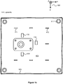
- the heating resistors can be located, for example, on the lower surface of the second plate 103, as the heating resistors 171 and 172 shown in figures 1 a and 1c, and/or on the upper surface of the first plate 102, as the heating resistors 173, 174 and 175 shown in figures 1 a and 1b. It is also possible to use a resistive sheet that is arranged to cover a part or parts of the interior surfaces of the measurement chamber 170.
- the controller 177 is arranged to control the electrical powers supplied to the heating resistors so that electrical power supplied to each heating resistor is proportional to a product of:
- the base module 100 includes several temperature sensors at different places of the measurement chamber 107, and the controller 177 is arranged to control the electrical power of each heating resistor on the basis of a temperature signal given by one of the temperature sensors.
- Heating resistors which are controlled on the basis of a temperature signal given by a certain temperature sensor, can be e.g. those heating resistors which are geometrically nearer to the said temperature sensor than to any other temperature sensor.
- the heating resistors are allocated into groups and each group is controlled with one of the temperature sensors.
- the electrical power supplied to each heating resistor can be controlled to be proportional to a balancing coefficient specific to that particular heating resistor.
- the base module of the optical measurement instrument illustrated in figures 1a-1c includes temperature sensors 176, 176' and 176" located on the lower surface of the second plate 103.
- the temperature sensor 176 is shown in figure 1 a and in figure 1c that shows a schematic illustration of a view seen upwards from the line A-A of figure 1a , and the temperature sensors 176' and 176" are shown in figure 1c .
- the controller 177 is arranged to control the driving voltage of each of the one or more heating resistors with the pulse width modulation (PWM) in order to control the electrical power of that heating resistor.
- PWM pulse width modulation
- the controller 177 is arranged to operate as a proportional-integrative-derivative (PID) regulator for controlling the electrical power supplied to each of the one or more heating resistors on the basis of the one or more temperature signals given by the one or more temperature sensors.
- PID proportional-integrative-derivative
- the electrical power supplied to R 1 can be proportional to B 1 ⁇ q and the electrical power supplied to R 2 can be proportional to B 2 ⁇ q, wherein the quantity q is PID-controlled on the basis of the difference between T and a reference temperature T ref .
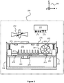
- FIG. 2 shows a schematic illustration of a section view of a base module 200 according to an embodiment of the invention.
- the base module includes a mechanical structure forming a measurement chamber 270.
- the mechanical structure forming the measurement chamber includes a first plate 202, a second plate 203 substantially parallel with the first plate and movably supported with respect to the first plate.
- the second plate is movable in a direction substantially perpendicular to the first and second plates, i.e. the second plate is movable in the positive and negative z-direction of the co-ordinate system 290.
- the mechanical structure forming the measurement chamber further includes walls 204 extending from outer edges of the first plate to outer edges of the second plate.
- the second plate 203 includes at least one fastening interface 207 suitable for an optical measurement element to be mounted to the second plate.
- the first plate 202 may include at least one fastening interface 280 suitable for an optical measurement element to be mounted to the first plate.
- the base module includes a reception device 201 inside the measurement chamber for receiving samples to be measured.
- the base module further includes one or more heating resistors 271, 272, 273, 274 and 275 arranged to warm the measurement chamber 270, and one or more temperature sensors 276 arranged to produce one or more temperature signals responsive to temperature of the measurement chamber.
- a base module further comprises a controller 277 arranged to control electrical power supplied to each of the one or more heating resistors on the basis of the one or more temperature signals produced by the one or more temperature sensors 276.
- Arrows 279 in figure 2 represent one or more temperature signals produced by the one or more temperature sensors and arrows 278 represent one or more driving voltages of the one or more heating resistors.
- the controller 277 is arranged to control the electrical powers supplied to the heating resistors so that the electrical power supplied to a first one of the heating resistors is proportional to B 1 ⁇ q and the electrical power supplied to a second one of the heating resistors is proportional to B 2 ⁇ q, wherein q is a quantity controlled on the basis of a certain temperature signal, B 1 is a pre-determined balancing coefficient specific to the first one of the heating resistors, and B 2 is a pre-determined balancing coefficient specific to the second one of the heating resistors.
- the balancing coefficient B 1 may have a different value than the balancing coefficient B 2 in order to compensate the effect of differences in temperature/power-characteristics related to surroundings of the first and second ones of the heating resistors.
- a base module according to an embodiment of the invention comprises temperature sensors placed at different places of the measurement chamber.
- the controller 277 is arranged to control the electrical power supplied to each of the heating resistors on the basis of a temperature signal produced by a particular temperature sensor that, from among all the temperature sensors, is nearest to the heating resistor under consideration.
- a base module according to an embodiment of the invention comprises a blower 282 arranged to blow cooling air towards outer walls of the measurement chamber 270.
- the controller 277 is arranged to control the operation of the blower on the basis of the one or more temperature signals. For example, if there are more than one temperature signals, the operation of the blower can be controlled e.g. on the basis of an arithmetic average of the temperature signals or on the basis of the maximum of temperatures indicated by the temperature signals.
- a base module according to an embodiment of the invention comprises a blower 281 arranged to blow cooling air into the measurement chamber.
- the controller 277 is arranged to control the operation of the blower on the basis of the one or more temperature signals.
- Figure 3 shows a flow chart of a method according to an embodiment of the invention for controlling temperature of samples being measured with an optical measurement instrument.
- the method comprises:
- the measurement chamber is warmed with many heating resistors placed at different places of the measurement chamber in order to create a sufficiently uniform temperature field in the measurement chamber.
- the electrical powers supplied to the heating resistors are controlled so that the electrical power supplied to a first one of the heating resistors is proportional to B 1 ⁇ q and the electrical power supplied to a second one of the heating resistors is proportional to B 2 ⁇ q, wherein q is a quantity controlled on the basis of a certain temperature signal, B 1 is a pre-determined balancing coefficient specific to the first one of the heating resistors, and B 2 is a pre-determined balancing coefficient specific to the second one of the heating resistors.
- the balancing coefficient B 1 may have a different value than the balancing coefficient B 2 in order to compensate effect of differences in temperature/power-characteristics related to surroundings of the first and second ones of the heating resistors.
- the at least one temperature sensor includes temperature sensors placed at different places of the measurement chamber and the electrical power supplied to each of the heating resistors is controlled on the basis the temperature signal produced by the particular temperature sensor nearest to the heating resistor under consideration.
- a method according to an embodiment of the invention further comprises controlling a blower arranged to blow cooling air towards outer walls of the measurement chamber on the basis of the one or more temperature signals.
- a method according to an embodiment of the invention further comprises controlling a blower arranged to blow cooling air into the measurement chamber on the basis of the one or more temperature signals.
- the electrical power of each heating resistor is controlled by controlling driving voltage of that heating resistor with the pulse width modulation (PWM).
- PWM pulse width modulation
- the electrical power of each heating resistor is controlled with a proportional-integrative-derivative (PID) regulator on the basis of the one or more temperature signals.
- PID proportional-integrative-derivative
- the electrical power supplied to R 1 can be proportional to B 1 ⁇ q and the electrical power supplied to R 2 can be proportional to B 2 ⁇ q, wherein the quantity q is PID-controlled on the basis of the difference between T and a reference temperature T ref .
Landscapes
- Physics & Mathematics (AREA)
- General Physics & Mathematics (AREA)
- Engineering & Computer Science (AREA)
- Health & Medical Sciences (AREA)
- Automation & Control Theory (AREA)
- Biochemistry (AREA)
- Analytical Chemistry (AREA)
- General Health & Medical Sciences (AREA)
- Chemical & Material Sciences (AREA)
- Immunology (AREA)
- Pathology (AREA)
- Life Sciences & Earth Sciences (AREA)
- Nuclear Medicine, Radiotherapy & Molecular Imaging (AREA)
- Remote Sensing (AREA)
- Investigating, Analyzing Materials By Fluorescence Or Luminescence (AREA)
Description
- The invention relates to a method for controlling temperature of samples being measured with an optical measurement instrument. Furthermore, the invention relates to a base module for an optical measurement instrument. The base module can be used as a platform with the aid of which different optical measurement instruments provided with measurement temperature control can be constructed using different optical measurement elements such as for example lenses, fibres, detectors, light sources, etc. An optical measurement can be, for example but not necessarily, an absorption measurement, a photoluminescence measurement, or a chemiluminescence measurement. Furthermore, the invention relates to an optical measurement instrument.
- The work in analytical biochemical laboratories and in clinical laboratories is often based on different tags or labels coupled on macromolecules under inspection. Typical labels used are different radioactive isotopes, enzymes, different fluorescent molecules and e.g. fluorescent chelates of rare earth metals. Detection of enzyme labels can be performed by utilizing its natural biochemical function, i.e. to alter the physical properties of molecules. In enzyme immunoassays colourless substances are catalysed by enzyme to colourful substances or non-fluorescent substances to fluorescent substances. The colourful substances can be measured with absorption measurement, i.e. photometric measurement. In the absorption measurement the intensity of filtered and stabilized beam is first measured without any sample and then the sample inside one plate is measured. The absorbance i.e. the absorption values are then calculated.
- The fluorescent substances can be measured with fluorescent measurement that is generally used for measuring quantities of fluorescent label substance in a sample. The most photoluminescence labels are based on molecular photoluminescence process. In this process optical radiation is absorbed by the ground state of a molecule. Due to the absorption of energy the quantum molecule rises into higher excited state. After the fast vibrational relaxation the molecule returns back to its ground state and the excess energy is released as an optical quantum. Due to losses in this process the average absorbed energies are higher than the average emitted energies. A further measurement method is chemiluminescence measurement where emission of a substance is measured from a sample without excitation by illumination. Thus a photoluminometer suitable for photoluminescence measurements can also be used as a chemiluminometer.
- Further, there is an analysing method called Amplified Luminescent Proximity Homogeneous Assay or AlphaScreen™. The function of the AlphaScreen™ method is based on the use of small beads that attach to the molecules under study. There are two types of beads that are coated with a material acting either as a donor or acceptor of singlet-state oxygen. The measurement starts, when the liquid sample is illuminated by light with a suitable wavelength e.g. 680 nm. After this, the material in the donor bead converts ambient oxygen into singlet-state oxygen. The single-state molecules have a short lifetime and they can reach only about a 200 nm distance by diffusion in the liquid. If the chemical reaction in question has taken place, both the donor and acceptor beads are bound to the same molecule and so they are sufficiently close to each other. In this case the singlet-state oxygen may reach the acceptor bead where a series of reactions is started. As the last phase of the reaction the coating material in the acceptor beads emits photons in the 500-700 nm range. If the chemical reaction has not taken place the singlet-state oxygen cannot reach the acceptor bead and the emission light is not detected. By measuring the intensity of light it is possible to conclude the efficiency of the chemical reaction.
- An optical measurement instrument suitable for performing some or all of the measurements of the kind described above comprises typically at least one excitation light source for producing excitation beams to one or more samples to be measured at each time. Each excitation light source can be for example a flash lamp or a laser source. An optical path from an excitation light source to a sample may contain for example lenses, fibers, mirrors, dichroic mirrors, optical filters, monochromators and/or other optical elements. The optical measurement instrument further comprises at least one detector for detecting emission beams emitted by the samples to be measured at each time, and for producing detection signals responsive to the detected emission beams. Each detector can be for example a photo-diode or a photo-multiplier tube. An optical path from the sample to the detector may contain for example lenses, fibers, mirrors, dichroic mirrors, optical filters, monochromators, and/or other optical elements. The optical measurement instrument may further comprise a processing device for producing a measurement result for each sample to be measured on the basis of the detection signal related to that sample.
- The optical measurement instrument comprises a reception device for receiving samples to be measured. Each sample to be measured is stored in one of a plurality of sample wells that are built on e.g. a microtitration plate or some other sample support element. The reception device can be, for example, a movable sledge adapted to receive the microtitration plate or the other sample support element. Due to the fact that the reception device allows moving the microtitration plate or the other sample support element, the samples can be measured in a temporally successive manner so that each sample is in turn the sample that is currently being measured. In order to maximize quality of the measurement results obtained with the optical measurements, temperature of the samples being measured is tried to be kept as close as possible to an optimum measurement temperature.
- Publication
US6977722 discloses an optical measurement instrument that includes an enclosure that is arranged to surround a reception device for receiving samples to be measured. The enclosure constitutes a measurement chamber arranged to protect the samples to be measured against undesired stray light and thermal radiation from the surroundings, and thus, inter alia, to keep the samples at a relatively steady temperature. An inconvenience related to the construction described above is that the temperature in the measurement chamber may, however, slowly wander along with changes of the temperature of the surroundings. - In accordance with a first aspect of the invention, there is provided a new optical measurement instrument. The optical measurement instrument according to the invention comprises:
- optical measurement elements including an excitation light source arranged to produce an excitation beam for at least one of samples to be measured and a detector arranged to detect an emission beam emitted by one of the samples to be measured and to produce a detection signal responsive to the detected emission beam,
- a mechanical structure for forming a measurement chamber and for supporting one or more of the optical measurement elements,
- a reception device inside the measurement chamber for receiving the samples to be measured,
- heating resistors placed at different places of the measurement chamber and arranged to warm the measurement chamber,
- at least one temperature sensor arranged to produce a temperature signal responsive to temperature of the measurement chamber, and
- a controller arranged to control electrical powers supplied to the heating resistors on the basis of the temperature signal,
- As the temperature of the measurement chamber is actively controlled with the aid of the heating resistors, the at least one temperature sensor, and the controller, the measurement chamber can be more easily kept at a desired temperature than in conjunction with the optical measurement instrument according to the prior art described earlier in this document. Value of each balancing coefficient depends on temperature/power-characteristics related to surroundings of the respective heating resistor. With the aid of the balancing coefficients, it is possible to achieve a desired temperature distribution (e.g. a flat temperature distribution) in a measurement chamber also in case where the temperature is measured only from a single spot. Values of the balancing coefficient may be different for different temperatures and/or temperature distributions. Hence, a desired temperature distribution can be achieved without a need for multiple measurements and multivariable control systems where the power sharing between heating resistors has to be determined on-line during operation of a measurement instrument.
- In accordance with a second aspect of the invention, there is provided a new base module for an optical measurement instrument. The base module can be used as a platform with the aid of which different optical measurement instruments provided with measurement temperature control can be constructed using different optical measurement elements such as for example lenses, fibres, detectors, light sources, etc. The base module according to the invention comprises:
- a mechanical structure for forming a measurement chamber and for supporting one or more optical measurement elements,
- a reception device inside the measurement chamber for receiving samples to be measured,
- heating resistors placed at different places of the measurement chamber, each heating resistor being arranged to warm the measurement chamber,
- at least one temperature sensor, each temperature sensor being arranged to produce a temperature signal responsive to temperature of the measurement chamber, and
- a controller arranged to control electrical power supplied to each of the at least one heating resistor on the basis of the at least one temperature signal produced by the at least one temperature sensor,
- The base module may preferably but not necessarily further comprise a controller arranged to control electrical power supplied to each of the at least one heating resistor on the basis of the temperature signal.
- In accordance with a third aspect of the invention, there is provided a new method for controlling temperature of samples being measured with an optical measurement instrument. The method according to the invention comprises:
- producing, with at least one temperature sensor, a temperature signal responsive to temperature of a measurement chamber of the optical measurement instrument, the samples being located in the measurement chamber,
- controlling electrical powers supplied to heating resistors placed at different places of the measurement chamber on the basis of the temperature signal, and
- warming the measurement chamber with the heating resistors,
- A number of exemplifying embodiments of the invention are described in accompanied dependent claims.
- Various exemplifying embodiments of the invention both as to constructions and to methods of operation, together with additional objects and advantages thereof, will be best understood from the following description of specific exemplifying embodiments when read in connection with the accompanying drawings.
- The verbs "to comprise" and "to include" are used in this document as open limitations that neither exclude nor require the existence of unrecited features. The features recited in depending claims are mutually freely combinable unless otherwise explicitly stated.
- The exemplifying embodiments of the invention and their advantages are explained in greater detail below in the sense of examples and with reference to the accompanying drawings, in which:
-
figure 1a shows a schematic illustration of a section view of an optical measurement instrument according to an embodiment of the invention, -
figure 1b shows a schematic illustration of a view seen downwards from line A-A offigure 1 a, -
figure 1c shows a schematic illustration of a view seen upwards from the line A-A offigure 1a , -
figure 2 shows a schematic illustration of a section view of a base module according to an embodiment of the invention, and -
figure 3 shows a flow chart of a method according to an embodiment of the invention for controlling temperature of samples being measured with an optical measurement instrument. -
Figure 1 a shows a schematic illustration of a side view of an optical measurement instrument according to an embodiment of the invention. The optical measurement instrument includes abase module 100 that includes a mechanical structure that forms ameasurement chamber 170 and acts as a support onto which one or more optical measurement elements can be mounted. The mechanical structure forming themeasurement chamber 170 includes afirst plate 102 and asecond plate 103 that is substantially parallel and, in a direction perpendicular to the first plate, overlapping with the first plate. Thesecond plate 103 is movably supported with respect to thefirst plate 102 so that the second plate is movable in the direction substantially perpendicular to the first and second plates, i.e. the second plate is moveable in the positive and negative z-directions of the co-ordinatesystem 190. Thesecond plate 103 is movably supported to thefirst plate 102 with threaded rods and with respective counterparts.Reference numbers second plate 103 movably with respect to thefirst plate 102 e.g. with the aid of toothed bars and respective gearwheels as counterparts of the toothed bars. The counterparts can be provided, for example, with servomotors arranged to move thesecond plate 103 in the positive or negative z-direction. The mechanical structure forming the measurement chamber further includeswalls 104 extending from outer edges of the first plate to outer edges of the second plate. In the exemplifying embodiment shown infigure 1a , the said walls include aflexible portion 105 fastened to outer edges of thesecond plate 103. Theflexible portion 105 allows the movement of the second plate relative to the first plate. It would be also possible to provide thesecond plate 103 e.g. with walls protruding towards the negative z-direction, overlapping thewalls 104, and being capable of sliding with respect to thewalls 104 thus allowing the movement of the second plate relative to the first plate. The optical measurement instrument includes, inside themeasurement chamber 170, areception device 101 for receivingsamples measurement chamber 170 is capable of protecting the samples against adverse stray light and thermal radiation from the surroundings. Thewalls 104 include adoor element 106 for enabling insertion of the samples to be measured into the measurement chamber. Thesecond plate 103 includes afastening interface 107 provided with an aperture. The fastening interface is suitable for anoptical measurement element 117 that is mounted to thesecond plate 103. The distance between theoptical measurement element 117 and the sample being measured can be adjusted by moving thesecond plate 103 in the positive or negative z-direction. Also thefirst plate 102 includes afastening interface 180 provided with an aperture and suitable for an optical measurement element. In the configuration shown infigure 1a , there is however no optical measurement element mounted to thefastening interface 180. - The
samples sample wells Figure 1b shows a schematic illustration of a view seen downwards from line A-A offigure 1a . As can be seen fromfigure 1b , the sample wells constitute in this exemplifying case a 7 x 7 array. In many cases there are, however, more sample wells in the array, e.g. 96 sample wells. Thereception device 101 has an interface for receiving a changeableseparate element 110, e.g. a microtitration plate, which includes the plurality of the sample wells. Thereception device 101 is often called a sample plate sledge. Thereception device 101 is mechanically connected to asupport rail 140 that is supported by support elements 140' in such a manner that thesupport rail 140 is movable in the directions defined by a two-headedarrow 141 shown infigure 1 b. Thereception device 101 is in turn movable along thesupport rail 140 in the directions defined by a two-headedarrow 142 shown infigure 1 b. Hence, thereception device 101 and thus also the sample wells are movable in parallel with the first andsecond plates reception device 101 and the sample wells are movable in the xy-plane defined by the co-ordinatesystem 190. Thus, each sample can be measured in its turn by changing the mechanical position of thereception device 101. In the exemplifying situation shown infigure 1a , a sample that is currently being measured is thesample 153 that is stored in the sample well 163. In principle it would be possible that theelement 110 including the sample wells is an integral part of the reception device, i.e. the reception device would include the sample wells, but several advantages are provided by having a changeable element that includes the plurality of sample wells. - Referring to
figure 1a , the optical measurement instrument includes anexcitation light source 120 that is arranged to produce an excitation light beam. Theexcitation light source 120 can be, for example, a flash lamp. The excitation light beam radiated by theexcitation light source 120 is collimated with alens 121 and directed through anoptical filter 122. Different optical filters can be selected for different wavelengths. The excitation light beam is then focused with alens 123 to an end of afibre optic guide 124, which guides the excitation light beam to theoptical measurement element 117. The fibre optic guide can be, for example, a bundle of fibres, such as 200 pieces of fibres with a diameter of e.g. 100 µm. The bundle of fibres can be used for mixing the excitation light beam in order to avoid an uneven distribution of light on a sample to be measured. The excitation light beam is reflected by adichroic mirror 125 to acollimating lens 126. The excitation light beam is then focused with alens 127 to thesample 153. - Photoluminescence emission beam from the
sample 153 is directed with thelenses dichroic mirror 125. The dichroic mirror is preferably designed so that it reflects excitation wavelength but transmits emission wavelengths. The emission beam is then divided into to two beams by asecond mirror 128. Themirror 128 is preferably a dichroic mirror, which functions as a filter so that an emission beam with a first emission wavelength is transmitted through the mirror and an emission beam with a second emission wavelength is reflected by the mirror. The emission beam that is transmitted through themirror 128 is collimated with alens 129, filtered with anoptical filter 130, and focused with alens 131 into an aperture of adetector 132. The emission beam that is reflected by themirror 128 is collimated with alens 133, filtered with anoptical filter 134, and focused with alens 135 into an aperture of adetector 136. Thedetector 132 can be for example a photo-multiplier tube and thedetector 136 can be for example a photo-diode. Thedetectors processing device 139 for producing a measurement result for each sample 151-157 to be measured on the basis of the detection signal related to the sample in question. - In the AlphaScreen™ measurement mode, the excitation light beam is received from an
excitation light source 137 that is a laser source. The excitation light beam is guided via anoptical guide 138 to thedichroic mirror 125. In the AlphaScreen™ measurement only onedetector 132 is used, preferably a photomultiplier tube. In the AlphaScreen™ measurement a transparent thermo plate (not shown) is preferably used for sealing the openings of the sample wells 161-167. - Referring to
figure 1a , thebase module 100 includes one or more heating resistors arranged to warm themeasurement chamber 170 and one or more temperature sensors arranged to produce one or more temperature signals responsive to temperature of the measurement chamber. The optical measurement instrument includes acontroller 177 arranged to control electrical power supplied to the one or more heating resistors on the basis of the one or more temperature signals. Therefore, there is a closed control loop for regulating the temperature of themeasurement chamber 170 and thus for keeping the samples 151-157 at an optimum measurement temperature. Thecontroller 177 can be an integral part of thebase module 100 or, alternatively, it can be a part of another portion of the optical measurement instrument.Arrows 179 infigure 1a represent one or more temperature signals produced by the one or more temperature sensors such as thetemperature sensor 176 andarrows 178 represent one or more driving voltages of the one or more heating resistors. In the simplest implementation there is only one heating resistor and only one temperature sensor. - In an optical measurement instrument according to an embodiment of the invention, the
base module 100 includes several heating resistors placed at different places of themeasurement chamber 170 in order to provide a sufficiently spatially uniform temperature field in the measurement chamber. The heating resistors can be located, for example, on the lower surface of thesecond plate 103, as theheating resistors figures 1 a and 1c, and/or on the upper surface of thefirst plate 102, as theheating resistors figures 1 a and 1b. It is also possible to use a resistive sheet that is arranged to cover a part or parts of the interior surfaces of themeasurement chamber 170. - In an optical measurement instrument according to an embodiment of the invention, the
controller 177 is arranged to control the electrical powers supplied to the heating resistors so that electrical power supplied to each heating resistor is proportional to a product of: - a quantity q controlled on the basis of a temperature signal produced by a temperature sensor, and
- a balancing coefficient B specific to that particular heating resistor,
- In an optical measurement instrument according to an embodiment of the invention, the
base module 100 includes several temperature sensors at different places of themeasurement chamber 107, and thecontroller 177 is arranged to control the electrical power of each heating resistor on the basis of a temperature signal given by one of the temperature sensors. Heating resistors, which are controlled on the basis of a temperature signal given by a certain temperature sensor, can be e.g. those heating resistors which are geometrically nearer to the said temperature sensor than to any other temperature sensor. In this case, the heating resistors are allocated into groups and each group is controlled with one of the temperature sensors. Furthermore, the electrical power supplied to each heating resistor can be controlled to be proportional to a balancing coefficient specific to that particular heating resistor. For example, if heating resistors R1 and R2 are controlled with a same temperature sensor and the heating resistor R1 has a balancing coefficient B1 and the heating resistor R2 has a balancing coefficient B2, the electrical power supplied to R1 can be proportional to B1 × q and the electrical power supplied to R2 can be proportional to B2 × q, where q is the quantity controlled on the basis of the temperature signal produced by the said temperature sensor. The base module of the optical measurement instrument illustrated infigures 1a-1c includestemperature sensors second plate 103. Thetemperature sensor 176 is shown infigure 1 a and infigure 1c that shows a schematic illustration of a view seen upwards from the line A-A offigure 1a , and thetemperature sensors 176' and 176" are shown infigure 1c . - In an optical measurement instrument according to an embodiment of the invention, the
controller 177 is arranged to control the driving voltage of each of the one or more heating resistors with the pulse width modulation (PWM) in order to control the electrical power of that heating resistor. - In an optical measurement instrument according to an embodiment of the invention, the
controller 177 is arranged to operate as a proportional-integrative-derivative (PID) regulator for controlling the electrical power supplied to each of the one or more heating resistors on the basis of the one or more temperature signals given by the one or more temperature sensors. For example, if electrical powers supplied to heating resistors R1 and R2 are controlled on the basis of a temperature signal T and the heating resistor R1 has a balancing coefficient B1 and the heating resistor R2 has a balancing coefficient B2, the electrical power supplied to R1 can be proportional to B1 × q and the electrical power supplied to R2 can be proportional to B2 × q, wherein the quantity q is PID-controlled on the basis of the difference between T and a reference temperature Tref. -
Figure 2 shows a schematic illustration of a section view of abase module 200 according to an embodiment of the invention. The base module includes a mechanical structure forming ameasurement chamber 270. The mechanical structure forming the measurement chamber includes afirst plate 202, asecond plate 203 substantially parallel with the first plate and movably supported with respect to the first plate. The second plate is movable in a direction substantially perpendicular to the first and second plates, i.e. the second plate is movable in the positive and negative z-direction of the co-ordinatesystem 290. The mechanical structure forming the measurement chamber further includeswalls 204 extending from outer edges of the first plate to outer edges of the second plate. Thesecond plate 203 includes at least onefastening interface 207 suitable for an optical measurement element to be mounted to the second plate. Also thefirst plate 202 may include at least onefastening interface 280 suitable for an optical measurement element to be mounted to the first plate. The base module includes areception device 201 inside the measurement chamber for receiving samples to be measured. The base module further includes one ormore heating resistors measurement chamber 270, and one ormore temperature sensors 276 arranged to produce one or more temperature signals responsive to temperature of the measurement chamber. - A base module according to an embodiment of the invention further comprises a
controller 277 arranged to control electrical power supplied to each of the one or more heating resistors on the basis of the one or more temperature signals produced by the one ormore temperature sensors 276.Arrows 279 infigure 2 represent one or more temperature signals produced by the one or more temperature sensors andarrows 278 represent one or more driving voltages of the one or more heating resistors. - In a base module according to an embodiment of the invention, the
controller 277 is arranged to control the electrical powers supplied to the heating resistors so that the electrical power supplied to a first one of the heating resistors is proportional to B1 × q and the electrical power supplied to a second one of the heating resistors is proportional to B2 × q, wherein q is a quantity controlled on the basis of a certain temperature signal, B1 is a pre-determined balancing coefficient specific to the first one of the heating resistors, and B2 is a pre-determined balancing coefficient specific to the second one of the heating resistors. The balancing coefficient B1 may have a different value than the balancing coefficient B2 in order to compensate the effect of differences in temperature/power-characteristics related to surroundings of the first and second ones of the heating resistors. - A base module according to an embodiment of the invention comprises temperature sensors placed at different places of the measurement chamber. In a base module according to an embodiment of the invention, the
controller 277 is arranged to control the electrical power supplied to each of the heating resistors on the basis of a temperature signal produced by a particular temperature sensor that, from among all the temperature sensors, is nearest to the heating resistor under consideration. - A base module according to an embodiment of the invention comprises a
blower 282 arranged to blow cooling air towards outer walls of themeasurement chamber 270. In a base module according to an embodiment of the invention, thecontroller 277 is arranged to control the operation of the blower on the basis of the one or more temperature signals. For example, if there are more than one temperature signals, the operation of the blower can be controlled e.g. on the basis of an arithmetic average of the temperature signals or on the basis of the maximum of temperatures indicated by the temperature signals. - A base module according to an embodiment of the invention comprises a
blower 281 arranged to blow cooling air into the measurement chamber. In a base module according to an embodiment of the invention, thecontroller 277 is arranged to control the operation of the blower on the basis of the one or more temperature signals. -
Figure 3 shows a flow chart of a method according to an embodiment of the invention for controlling temperature of samples being measured with an optical measurement instrument. The method comprises: - producing, in a
phase 301 using one or more temperature sensors, one or more temperature signals responsive to temperature of a measurement chamber of the optical measurement instrument, the samples being located in the measurement chamber, - controlling, in a
phase 302, electrical power supplied to one or more heating resistors on the basis of the one or more temperature signals, and - warming, in a
phase 303, the measurement chamber with the one or more heating resistor. - In a method according to an embodiment of the invention, the measurement chamber is warmed with many heating resistors placed at different places of the measurement chamber in order to create a sufficiently uniform temperature field in the measurement chamber.
- In a method according to an embodiment of the invention, the electrical powers supplied to the heating resistors are controlled so that the electrical power supplied to a first one of the heating resistors is proportional to B1 × q and the electrical power supplied to a second one of the heating resistors is proportional to B2 × q, wherein q is a quantity controlled on the basis of a certain temperature signal, B1 is a pre-determined balancing coefficient specific to the first one of the heating resistors, and B2 is a pre-determined balancing coefficient specific to the second one of the heating resistors. The balancing coefficient B1 may have a different value than the balancing coefficient B2 in order to compensate effect of differences in temperature/power-characteristics related to surroundings of the first and second ones of the heating resistors.
- In a method according to an embodiment of the invention, the at least one temperature sensor includes temperature sensors placed at different places of the measurement chamber and the electrical power supplied to each of the heating resistors is controlled on the basis the temperature signal produced by the particular temperature sensor nearest to the heating resistor under consideration.
- A method according to an embodiment of the invention further comprises controlling a blower arranged to blow cooling air towards outer walls of the measurement chamber on the basis of the one or more temperature signals.
- A method according to an embodiment of the invention further comprises controlling a blower arranged to blow cooling air into the measurement chamber on the basis of the one or more temperature signals.
- In a method according to an embodiment of the invention, the electrical power of each heating resistor is controlled by controlling driving voltage of that heating resistor with the pulse width modulation (PWM).
- In a method according to an embodiment of the invention, the electrical power of each heating resistor is controlled with a proportional-integrative-derivative (PID) regulator on the basis of the one or more temperature signals. For example, if electrical powers supplied to heating resistors R1 and R2 are controlled on the basis of a temperature signal T and the heating resistor R1 has a balancing coefficient B1 and a heating resistor R2 has a balancing coefficient B2, the electrical power supplied to R1 can be proportional to B1 × q and the electrical power supplied to R2 can be proportional to B2 × q, wherein the quantity q is PID-controlled on the basis of the difference between T and a reference temperature Tref.
Claims (11)
- A base module (100, 200) for an optical measurement instrument, the base module comprising:- a mechanical structure for forming a measurement chamber (170, 270) and for supporting one or more optical measurement elements,- a reception device (101, 201) inside the measurement chamber for receiving samples to be measured,- heating resistors (171-175, 271-275) placed at different places of the measurement chamber, each heating resistor being arranged to warm the measurement chamber,- a first temperature sensor (176, 276) arranged to produce a first temperature signal responsive to temperature of the measurement chamber, and- a controller (177, 277) arranged to control electrical power supplied to each of the heating resistors on the basis of the first temperature signal produced by the first temperature sensor,characterized in that the controller is arranged to control the electrical powers supplied to the heating resistors so that the electrical power supplied to a first one of the heating resistors is proportional to B1 × q and the electrical power supplied to a second one of the heating resistors is proportional to B2 × q, wherein q is a quantity controlled on the basis of the first temperature signal, B1 is a pre-determined balancing coefficient specific to the first one of the heating resistors, and B2 is a pre-determined balancing coefficient specific to the second one of the heating resistors, the balancing coefficient B1 having a different value than the balancing coefficient B2, the values of B1 and B2 being mutually different in order to compensate for effect of differences in temperature/power -characteristics related to surroundings of the first and second ones of the heating resistors.
- A base module according to claim 1, wherein the base module further comprises a second temperature sensor (176', 176") and the controller is arranged to control electrical powers supplied to other heating resistors that are nearer to the second temperature sensor than to the first temperature sensor on the basis a second temperature signal produced by the second temperature sensor, the first and second temperature sensors being placed at different places of the measurement chamber.
- A base module according to claim 1 or 2, wherein the base module comprises a blower (282) arranged to blow cooling air towards outer walls of the measurement chamber.
- A base module according to any of claims 1-3, wherein the base module comprises a blower (281) arranged to blow cooling air into the measurement chamber.
- A base module according to any of claims 1-4, wherein the mechanical structure for forming the measurement chamber (170, 270) comprises:- a first plate (102, 202),- a second plate (103, 203) substantially parallel with the first plate and movably supported with respect to the first plate, the second plate being movable in a direction substantially perpendicular to the first and second plates, and- walls (104, 204) extending from outer edges of the first plate to outer edges of the second plate,wherein the measurement chamber is constituted by the walls and the first and second plates and the second plate comprises a fastening interface (107, 207) suitable for an optical measurement element to be mounted to the second plate.
- A base module according to claim 5, wherein at least one of the heating resistors (173-175, 273-275) is mounted on the surface of the first plate.
- A base module according to claim 5 or 6, wherein at least one of the heating resistors (171, 172, 271, 272) is mounted on the surface of the second plate.
- A base module according to any of claims 1-7, wherein the controller is arranged to control driving voltage of each of the heating resistors with pulse width modulation (PWM) for controlling the electrical power of that heating resistor.
- A base module according to any of claims 1-8, wherein the controller is arranged to operate as a proportional-integrative-derivative (PID) regulator for controlling the electrical powers supplied to the first and second ones of heating resistors on the basis of the first temperature signal produced by the first temperature sensor.
- An optical measurement instrument comprising optical measurement elements (117), at least one of the optical measurement elements including an excitation light source (120, 137) arranged to produce an excitation beam for at least one of samples (151-157) to be measured, and at least one of the optical measurement elements including a detector (132, 136) arranged to detect an emission beam emitted by one of the samples to be measured and to produce a detection signal responsive to the detected emission beam, characterized in that the optical measurement instrument further comprises a base module (100) according to any of the preceding claims and at least one of the optical measurement elements is mounted to the mechanical structure forming the measurement chamber (170).
- A method for controlling temperature of samples being measured with an optical measurement instrument, the method comprising:- producing (301), with a temperature sensor, a temperature signal responsive to temperature of a measurement chamber of the optical measurement instrument, the samples being located in the measurement chamber,- controlling (302) electrical powers supplied to heating resistors placed at different places of the measurement chamber on the basis of the temperature signal, and- warming (303) the measurement chamber with the heating resistors,characterized in that the electrical powers supplied to the heating resistors are controlled so that the electrical power supplied to a first one of the heating resistors is proportional to B1 × q and the electrical power supplied to a second one of the heating resistors is proportional to B2 × q, wherein q is a quantity controlled on the basis of the temperature signal, B1 is a pre-determined balancing coefficient specific to the first one of the heating resistors, and B2 is a pre-determined balancing coefficient specific to the second one of the heating resistors, the balancing coefficient B1 having a different value than the balancing coefficient B2 ,the values of B1 and B2 being mutually different in order to compensate for effect of differences in temperature/power -characteristics related to surroundings of the first and second ones of the heating resistors.
Applications Claiming Priority (2)
| Application Number | Priority Date | Filing Date | Title |
|---|---|---|---|
| FI20096021A FI20096021A0 (en) | 2009-10-06 | 2009-10-06 | Optical measuring instrument |
| PCT/FI2010/050774 WO2011042602A1 (en) | 2009-10-06 | 2010-10-06 | An optical measurement instrument |
Publications (2)
| Publication Number | Publication Date |
|---|---|
| EP2486465A1 EP2486465A1 (en) | 2012-08-15 |
| EP2486465B1 true EP2486465B1 (en) | 2017-12-06 |
Family
ID=41263438
Family Applications (1)
| Application Number | Title | Priority Date | Filing Date |
|---|---|---|---|
| EP10776758.4A Active EP2486465B1 (en) | 2009-10-06 | 2010-10-06 | An optical measurement instrument |
Country Status (4)
| Country | Link |
|---|---|
| US (1) | US8896820B2 (en) |
| EP (1) | EP2486465B1 (en) |
| FI (1) | FI20096021A0 (en) |
| WO (1) | WO2011042602A1 (en) |
Families Citing this family (2)
| Publication number | Priority date | Publication date | Assignee | Title |
|---|---|---|---|---|
| CN102565016B (en) * | 2011-12-30 | 2014-05-07 | 北京农业智能装备技术研究中心 | Detected temperature effect compensation device and method based on fluorescent quenching sensor |
| TW201843446A (en) * | 2017-04-13 | 2018-12-16 | 律祈醫創股份有限公司 | Photothermal reaction analyzer |
Citations (1)
| Publication number | Priority date | Publication date | Assignee | Title |
|---|---|---|---|---|
| US3825725A (en) * | 1968-11-29 | 1974-07-23 | Coltron Ind | Thermal systems incorporating apparatus and methods for simulating time related temperatures |
Family Cites Families (29)
| Publication number | Priority date | Publication date | Assignee | Title |
|---|---|---|---|---|
| US2272836A (en) * | 1937-03-12 | 1942-02-10 | Siemens Ag | Hemadynamometer |
| US2759354A (en) * | 1950-09-26 | 1956-08-21 | Leeds & Northrup Co | Isothermal systems for gas analysis |
| BE508203A (en) * | 1951-01-04 | |||
| US2763151A (en) * | 1952-08-18 | 1956-09-18 | Hays Corp | Differential oxygen analyzer |
| FR1206107A (en) * | 1958-05-09 | 1960-02-08 | Electrochimie Soc | Thermal gas analysis cells and measuring devices |
| US3763422A (en) * | 1971-10-21 | 1973-10-02 | Corning Glass Works | Method and apparatus for electrochemical analysis of small samples of blood |
| DE2629051C2 (en) * | 1976-06-29 | 1985-07-18 | Günther Dipl.-Ing. 2201 Kollmar Weber | Heat transfer meter |
| FR2389886B1 (en) * | 1977-05-04 | 1981-08-07 | Elf Union | |
| SU763791A1 (en) * | 1977-11-09 | 1980-09-15 | Институт Химии Ан Эстонской Сср | Apparatus for detecting the presence of water added to milk in determining naturalness of milk |
| FI833076A0 (en) | 1983-08-30 | 1983-08-30 | Labsystems Oy | ANORDNING FOER MAETNING AV UPPVAERMBARA VAETSKEPROV |
| US5207987A (en) | 1990-05-21 | 1993-05-04 | Pb Diagnostic Systems Inc. | Temperature controlled chamber for diagnostic analyzer |
| CA2096198A1 (en) | 1992-06-26 | 1993-12-27 | Christopher J. Macko | Automated clinical analyzer with temperature control |
| US5557398A (en) | 1994-04-15 | 1996-09-17 | Molecular Devices Corporation | Photometric device |
| JP3114139B2 (en) * | 1995-01-24 | 2000-12-04 | 株式会社山武 | Thermal conductivity meter |
| FR2735866B1 (en) * | 1995-06-22 | 1997-08-29 | Crevoiserat Jean Michel | PROBE FOR MEASURING THE PARTIAL PRESSURE OF OXYGEN IN DOMESTIC AND INDUSTRIAL CHIMNEYS |
| EP1442794B1 (en) | 1996-06-04 | 2006-03-29 | University Of Utah Research Foundation | System and method for carrying out and monitoring biological processes |
| JP2004534226A (en) | 2001-06-29 | 2004-11-11 | メソ スケイル テクノロジーズ,エルエルシー | Assay plate, reader system and method for luminescence test measurement |
| AU2002333497A1 (en) | 2001-08-21 | 2003-03-10 | Bestmann, Lukas | Thermo-optical analysis system for biochemical reactions |
| DE10251130B4 (en) * | 2002-11-02 | 2005-04-21 | Dräger Medical AG & Co. KGaA | Sample gas cuvette for a device for measuring the concentration of a paramagnetic gas |
| US7981362B2 (en) | 2003-11-04 | 2011-07-19 | Meso Scale Technologies, Llc | Modular assay plates, reader systems and methods for test measurements |
| EP1541237A3 (en) | 2003-12-10 | 2006-02-01 | Samsung Electronics Co., Ltd. | Polymerase chain reaction (pcr) module and multiple pcr system using the same |
| JP2006113724A (en) * | 2004-10-13 | 2006-04-27 | Omron Corp | Control method, temperature control method, temperature controller, heat treatment apparatus, program, and recording medium |
| DE102006014266A1 (en) * | 2005-12-23 | 2007-06-28 | Robert Bosch Gmbh | Two cells-broadband-lambda sensor for internal combustion engine, has one of heater connections connected with connections of pump cells or Nernst cells, and control device provided for clocked operation of heater and for signal evaluation |
| CA2877959C (en) * | 2006-08-22 | 2017-06-13 | Charles F. Barry | Apparatus and method for thermal stabilization of pcb-mounted electronic components within an enclosed housing |
| JP4553266B2 (en) * | 2007-04-13 | 2010-09-29 | 東京エレクトロン株式会社 | Heat treatment apparatus, automatic control constant adjustment method, and storage medium |
| JP5309160B2 (en) * | 2008-02-05 | 2013-10-09 | ポカード・ディアグノスティクス・リミテッド | System for identifying bacteria in biological samples |
| US8746008B1 (en) * | 2009-03-29 | 2014-06-10 | Montana Instruments Corporation | Low vibration cryocooled system for low temperature microscopy and spectroscopy applications |
| CA2756710C (en) * | 2009-04-27 | 2013-06-04 | Rostrum Medical Innovations Inc. | Apparatus and method for monitoring the degree of integration between the functions of the heart and the lungs, and the therapeutic success of resuscitative interventions |
| US8278629B2 (en) * | 2009-08-19 | 2012-10-02 | National Tsing Hua University | Observation chamber for studying temperature-dependent events and method thereof |
-
2009
- 2009-10-06 FI FI20096021A patent/FI20096021A0/en not_active Application Discontinuation
-
2010
- 2010-10-06 WO PCT/FI2010/050774 patent/WO2011042602A1/en not_active Ceased
- 2010-10-06 EP EP10776758.4A patent/EP2486465B1/en active Active
- 2010-10-06 US US13/500,333 patent/US8896820B2/en active Active
Patent Citations (1)
| Publication number | Priority date | Publication date | Assignee | Title |
|---|---|---|---|---|
| US3825725A (en) * | 1968-11-29 | 1974-07-23 | Coltron Ind | Thermal systems incorporating apparatus and methods for simulating time related temperatures |
Also Published As
| Publication number | Publication date |
|---|---|
| EP2486465A1 (en) | 2012-08-15 |
| US20120240692A1 (en) | 2012-09-27 |
| WO2011042602A1 (en) | 2011-04-14 |
| FI20096021A0 (en) | 2009-10-06 |
| US8896820B2 (en) | 2014-11-25 |
Similar Documents
| Publication | Publication Date | Title |
|---|---|---|
| US6891618B2 (en) | Optical instrument and process for measurement of samples | |
| US20160266362A1 (en) | Compact Microscope | |
| EP2382476B1 (en) | An arrangement and a method for controlling a measurement head of an optical measurement instrument | |
| US20020176801A1 (en) | Fluid delivery and analysis systems | |
| US7843568B2 (en) | Enhanced instrumentation and method for optical measurement of samples | |
| EP1517135B1 (en) | Instrument for optical measurement of samples | |
| US20040057870A1 (en) | Instrumentation for optical measurement of samples | |
| EP1704403B1 (en) | Multimode reader | |
| US8759789B2 (en) | Body module for an optical measurement instrument | |
| US6822741B2 (en) | Optical instrument and process for measurement of samples | |
| US8814427B2 (en) | Instrumentation and method for optical measurement of samples | |
| US20090212235A1 (en) | Scanning fluorescent reader with diffuser system | |
| US8896820B2 (en) | Optical measurement instrument | |
| EP1231472B1 (en) | Integrated fluid delivery and analysis system |
Legal Events
| Date | Code | Title | Description |
|---|---|---|---|
| PUAI | Public reference made under article 153(3) epc to a published international application that has entered the european phase |
Free format text: ORIGINAL CODE: 0009012 |
|
| 17P | Request for examination filed |
Effective date: 20120306 |
|
| AK | Designated contracting states |
Kind code of ref document: A1 Designated state(s): AL AT BE BG CH CY CZ DE DK EE ES FI FR GB GR HR HU IE IS IT LI LT LU LV MC MK MT NL NO PL PT RO RS SE SI SK SM TR |
|
| DAX | Request for extension of the european patent (deleted) | ||
| 17Q | First examination report despatched |
Effective date: 20130228 |
|
| REG | Reference to a national code |
Ref country code: DE Ref legal event code: R079 Ref document number: 602010047201 Country of ref document: DE Free format text: PREVIOUS MAIN CLASS: G05D0023190000 Ipc: G01N0021640000 |
|
| GRAP | Despatch of communication of intention to grant a patent |
Free format text: ORIGINAL CODE: EPIDOSNIGR1 |
|
| RIC1 | Information provided on ipc code assigned before grant |
Ipc: G01N 21/03 20060101ALI20170609BHEP Ipc: G05D 23/19 20060101ALI20170609BHEP Ipc: G01N 21/64 20060101AFI20170609BHEP |
|
| INTG | Intention to grant announced |
Effective date: 20170627 |
|
| GRAS | Grant fee paid |
Free format text: ORIGINAL CODE: EPIDOSNIGR3 |
|
| GRAA | (expected) grant |
Free format text: ORIGINAL CODE: 0009210 |
|
| AK | Designated contracting states |
Kind code of ref document: B1 Designated state(s): AL AT BE BG CH CY CZ DE DK EE ES FI FR GB GR HR HU IE IS IT LI LT LU LV MC MK MT NL NO PL PT RO RS SE SI SK SM TR |
|
| RAP1 | Party data changed (applicant data changed or rights of an application transferred) |
Owner name: PERKINELMER SINGAPORE PTE.LTD. |
|
| REG | Reference to a national code |
Ref country code: GB Ref legal event code: FG4D |
|
| REG | Reference to a national code |
Ref country code: AT Ref legal event code: REF Ref document number: 952820 Country of ref document: AT Kind code of ref document: T Effective date: 20171215 Ref country code: CH Ref legal event code: EP |
|
| REG | Reference to a national code |
Ref country code: IE Ref legal event code: FG4D |
|
| REG | Reference to a national code |
Ref country code: DE Ref legal event code: R096 Ref document number: 602010047201 Country of ref document: DE |
|
| REG | Reference to a national code |
Ref country code: CH Ref legal event code: NV Representative=s name: HEPP WENGER RYFFEL AG, CH |
|
| REG | Reference to a national code |
Ref country code: NL Ref legal event code: MP Effective date: 20171206 |
|
| REG | Reference to a national code |
Ref country code: LT Ref legal event code: MG4D |
|
| PG25 | Lapsed in a contracting state [announced via postgrant information from national office to epo] |
Ref country code: LT Free format text: LAPSE BECAUSE OF FAILURE TO SUBMIT A TRANSLATION OF THE DESCRIPTION OR TO PAY THE FEE WITHIN THE PRESCRIBED TIME-LIMIT Effective date: 20171206 Ref country code: NO Free format text: LAPSE BECAUSE OF FAILURE TO SUBMIT A TRANSLATION OF THE DESCRIPTION OR TO PAY THE FEE WITHIN THE PRESCRIBED TIME-LIMIT Effective date: 20180306 Ref country code: ES Free format text: LAPSE BECAUSE OF FAILURE TO SUBMIT A TRANSLATION OF THE DESCRIPTION OR TO PAY THE FEE WITHIN THE PRESCRIBED TIME-LIMIT Effective date: 20171206 Ref country code: SE Free format text: LAPSE BECAUSE OF FAILURE TO SUBMIT A TRANSLATION OF THE DESCRIPTION OR TO PAY THE FEE WITHIN THE PRESCRIBED TIME-LIMIT Effective date: 20171206 |
|
| REG | Reference to a national code |
Ref country code: AT Ref legal event code: MK05 Ref document number: 952820 Country of ref document: AT Kind code of ref document: T Effective date: 20171206 |
|
| PG25 | Lapsed in a contracting state [announced via postgrant information from national office to epo] |
Ref country code: HR Free format text: LAPSE BECAUSE OF FAILURE TO SUBMIT A TRANSLATION OF THE DESCRIPTION OR TO PAY THE FEE WITHIN THE PRESCRIBED TIME-LIMIT Effective date: 20171206 Ref country code: LV Free format text: LAPSE BECAUSE OF FAILURE TO SUBMIT A TRANSLATION OF THE DESCRIPTION OR TO PAY THE FEE WITHIN THE PRESCRIBED TIME-LIMIT Effective date: 20171206 Ref country code: RS Free format text: LAPSE BECAUSE OF FAILURE TO SUBMIT A TRANSLATION OF THE DESCRIPTION OR TO PAY THE FEE WITHIN THE PRESCRIBED TIME-LIMIT Effective date: 20171206 Ref country code: BG Free format text: LAPSE BECAUSE OF FAILURE TO SUBMIT A TRANSLATION OF THE DESCRIPTION OR TO PAY THE FEE WITHIN THE PRESCRIBED TIME-LIMIT Effective date: 20180306 Ref country code: GR Free format text: LAPSE BECAUSE OF FAILURE TO SUBMIT A TRANSLATION OF THE DESCRIPTION OR TO PAY THE FEE WITHIN THE PRESCRIBED TIME-LIMIT Effective date: 20180307 |
|
| PG25 | Lapsed in a contracting state [announced via postgrant information from national office to epo] |
Ref country code: NL Free format text: LAPSE BECAUSE OF FAILURE TO SUBMIT A TRANSLATION OF THE DESCRIPTION OR TO PAY THE FEE WITHIN THE PRESCRIBED TIME-LIMIT Effective date: 20171206 |
|
| PG25 | Lapsed in a contracting state [announced via postgrant information from national office to epo] |
Ref country code: EE Free format text: LAPSE BECAUSE OF FAILURE TO SUBMIT A TRANSLATION OF THE DESCRIPTION OR TO PAY THE FEE WITHIN THE PRESCRIBED TIME-LIMIT Effective date: 20171206 Ref country code: SK Free format text: LAPSE BECAUSE OF FAILURE TO SUBMIT A TRANSLATION OF THE DESCRIPTION OR TO PAY THE FEE WITHIN THE PRESCRIBED TIME-LIMIT Effective date: 20171206 Ref country code: CZ Free format text: LAPSE BECAUSE OF FAILURE TO SUBMIT A TRANSLATION OF THE DESCRIPTION OR TO PAY THE FEE WITHIN THE PRESCRIBED TIME-LIMIT Effective date: 20171206 |
|
| PG25 | Lapsed in a contracting state [announced via postgrant information from national office to epo] |
Ref country code: PL Free format text: LAPSE BECAUSE OF FAILURE TO SUBMIT A TRANSLATION OF THE DESCRIPTION OR TO PAY THE FEE WITHIN THE PRESCRIBED TIME-LIMIT Effective date: 20171206 Ref country code: SM Free format text: LAPSE BECAUSE OF FAILURE TO SUBMIT A TRANSLATION OF THE DESCRIPTION OR TO PAY THE FEE WITHIN THE PRESCRIBED TIME-LIMIT Effective date: 20171206 Ref country code: AT Free format text: LAPSE BECAUSE OF FAILURE TO SUBMIT A TRANSLATION OF THE DESCRIPTION OR TO PAY THE FEE WITHIN THE PRESCRIBED TIME-LIMIT Effective date: 20171206 Ref country code: IT Free format text: LAPSE BECAUSE OF FAILURE TO SUBMIT A TRANSLATION OF THE DESCRIPTION OR TO PAY THE FEE WITHIN THE PRESCRIBED TIME-LIMIT Effective date: 20171206 Ref country code: RO Free format text: LAPSE BECAUSE OF FAILURE TO SUBMIT A TRANSLATION OF THE DESCRIPTION OR TO PAY THE FEE WITHIN THE PRESCRIBED TIME-LIMIT Effective date: 20171206 |
|
| REG | Reference to a national code |
Ref country code: DE Ref legal event code: R097 Ref document number: 602010047201 Country of ref document: DE |
|
| PLBE | No opposition filed within time limit |
Free format text: ORIGINAL CODE: 0009261 |
|
| STAA | Information on the status of an ep patent application or granted ep patent |
Free format text: STATUS: NO OPPOSITION FILED WITHIN TIME LIMIT |
|
| 26N | No opposition filed |
Effective date: 20180907 |
|
| PG25 | Lapsed in a contracting state [announced via postgrant information from national office to epo] |
Ref country code: SI Free format text: LAPSE BECAUSE OF FAILURE TO SUBMIT A TRANSLATION OF THE DESCRIPTION OR TO PAY THE FEE WITHIN THE PRESCRIBED TIME-LIMIT Effective date: 20171206 Ref country code: DK Free format text: LAPSE BECAUSE OF FAILURE TO SUBMIT A TRANSLATION OF THE DESCRIPTION OR TO PAY THE FEE WITHIN THE PRESCRIBED TIME-LIMIT Effective date: 20171206 |
|
| REG | Reference to a national code |
Ref country code: BE Ref legal event code: MM Effective date: 20181031 |
|
| PG25 | Lapsed in a contracting state [announced via postgrant information from national office to epo] |
Ref country code: LU Free format text: LAPSE BECAUSE OF NON-PAYMENT OF DUE FEES Effective date: 20181006 Ref country code: MC Free format text: LAPSE BECAUSE OF FAILURE TO SUBMIT A TRANSLATION OF THE DESCRIPTION OR TO PAY THE FEE WITHIN THE PRESCRIBED TIME-LIMIT Effective date: 20171206 |
|
| REG | Reference to a national code |
Ref country code: IE Ref legal event code: MM4A |
|
| PG25 | Lapsed in a contracting state [announced via postgrant information from national office to epo] |
Ref country code: BE Free format text: LAPSE BECAUSE OF NON-PAYMENT OF DUE FEES Effective date: 20181031 Ref country code: FR Free format text: LAPSE BECAUSE OF NON-PAYMENT OF DUE FEES Effective date: 20181031 |
|
| PG25 | Lapsed in a contracting state [announced via postgrant information from national office to epo] |
Ref country code: IE Free format text: LAPSE BECAUSE OF NON-PAYMENT OF DUE FEES Effective date: 20181006 |
|
| PG25 | Lapsed in a contracting state [announced via postgrant information from national office to epo] |
Ref country code: MT Free format text: LAPSE BECAUSE OF NON-PAYMENT OF DUE FEES Effective date: 20181006 |
|
| PG25 | Lapsed in a contracting state [announced via postgrant information from national office to epo] |
Ref country code: TR Free format text: LAPSE BECAUSE OF FAILURE TO SUBMIT A TRANSLATION OF THE DESCRIPTION OR TO PAY THE FEE WITHIN THE PRESCRIBED TIME-LIMIT Effective date: 20171206 |
|
| PG25 | Lapsed in a contracting state [announced via postgrant information from national office to epo] |
Ref country code: PT Free format text: LAPSE BECAUSE OF FAILURE TO SUBMIT A TRANSLATION OF THE DESCRIPTION OR TO PAY THE FEE WITHIN THE PRESCRIBED TIME-LIMIT Effective date: 20171206 |
|
| PG25 | Lapsed in a contracting state [announced via postgrant information from national office to epo] |
Ref country code: MK Free format text: LAPSE BECAUSE OF NON-PAYMENT OF DUE FEES Effective date: 20171206 Ref country code: CY Free format text: LAPSE BECAUSE OF FAILURE TO SUBMIT A TRANSLATION OF THE DESCRIPTION OR TO PAY THE FEE WITHIN THE PRESCRIBED TIME-LIMIT Effective date: 20171206 Ref country code: HU Free format text: LAPSE BECAUSE OF FAILURE TO SUBMIT A TRANSLATION OF THE DESCRIPTION OR TO PAY THE FEE WITHIN THE PRESCRIBED TIME-LIMIT; INVALID AB INITIO Effective date: 20101006 |
|
| PG25 | Lapsed in a contracting state [announced via postgrant information from national office to epo] |
Ref country code: AL Free format text: LAPSE BECAUSE OF FAILURE TO SUBMIT A TRANSLATION OF THE DESCRIPTION OR TO PAY THE FEE WITHIN THE PRESCRIBED TIME-LIMIT Effective date: 20171206 Ref country code: IS Free format text: LAPSE BECAUSE OF FAILURE TO SUBMIT A TRANSLATION OF THE DESCRIPTION OR TO PAY THE FEE WITHIN THE PRESCRIBED TIME-LIMIT Effective date: 20180406 |
|
| P01 | Opt-out of the competence of the unified patent court (upc) registered |
Effective date: 20230526 |
|
| REG | Reference to a national code |
Ref country code: CH Ref legal event code: U11 Free format text: ST27 STATUS EVENT CODE: U-0-0-U10-U11 (AS PROVIDED BY THE NATIONAL OFFICE) Effective date: 20251101 |
|
| PGFP | Annual fee paid to national office [announced via postgrant information from national office to epo] |
Ref country code: DE Payment date: 20251029 Year of fee payment: 16 |
|
| PGFP | Annual fee paid to national office [announced via postgrant information from national office to epo] |
Ref country code: GB Payment date: 20251027 Year of fee payment: 16 |
|
| PGFP | Annual fee paid to national office [announced via postgrant information from national office to epo] |
Ref country code: FI Payment date: 20251027 Year of fee payment: 16 |
|
| PGFP | Annual fee paid to national office [announced via postgrant information from national office to epo] |
Ref country code: CH Payment date: 20251101 Year of fee payment: 16 |