EP2486320B1 - Hose connector lock - Google Patents
Hose connector lock Download PDFInfo
- Publication number
- EP2486320B1 EP2486320B1 EP10760398.7A EP10760398A EP2486320B1 EP 2486320 B1 EP2486320 B1 EP 2486320B1 EP 10760398 A EP10760398 A EP 10760398A EP 2486320 B1 EP2486320 B1 EP 2486320B1
- Authority
- EP
- European Patent Office
- Prior art keywords
- tractor
- body part
- trailer
- coupling
- end body
- Prior art date
- Legal status (The legal status is an assumption and is not a legal conclusion. Google has not performed a legal analysis and makes no representation as to the accuracy of the status listed.)
- Active
Links
Images

Classifications
-
- F—MECHANICAL ENGINEERING; LIGHTING; HEATING; WEAPONS; BLASTING
- F16—ENGINEERING ELEMENTS AND UNITS; GENERAL MEASURES FOR PRODUCING AND MAINTAINING EFFECTIVE FUNCTIONING OF MACHINES OR INSTALLATIONS; THERMAL INSULATION IN GENERAL
- F16L—PIPES; JOINTS OR FITTINGS FOR PIPES; SUPPORTS FOR PIPES, CABLES OR PROTECTIVE TUBING; MEANS FOR THERMAL INSULATION IN GENERAL
- F16L37/00—Couplings of the quick-acting type
- F16L37/22—Couplings of the quick-acting type in which the connection is maintained by means of balls, rollers or helical springs under radial pressure between the parts
-
- F—MECHANICAL ENGINEERING; LIGHTING; HEATING; WEAPONS; BLASTING
- F16—ENGINEERING ELEMENTS AND UNITS; GENERAL MEASURES FOR PRODUCING AND MAINTAINING EFFECTIVE FUNCTIONING OF MACHINES OR INSTALLATIONS; THERMAL INSULATION IN GENERAL
- F16L—PIPES; JOINTS OR FITTINGS FOR PIPES; SUPPORTS FOR PIPES, CABLES OR PROTECTIVE TUBING; MEANS FOR THERMAL INSULATION IN GENERAL
- F16L2201/00—Special arrangements for pipe couplings
- F16L2201/20—Safety or protective couplings
Definitions
- the present invention relates to a tractor and a trailer with an air brake hose connection system, the air brake connection system incorporating a lock.
- An articulated lorry comprising a tractor and trailer, has flexible air brake lines or hoses extending between tractor and trailer. These are coils of nylon tubing, known as Susie coils.
- the hoses are disconnectable from the trailer, but they are not disconnectable from the tractor.
- a primary hose a red hose
- a secondary hose a yellow hose
- the hoses are subject to considerable wear and tear, and can occasionally fail. The vehicle cannot be moved until the hose has been repaired; and repair must be carried out by a qualified fitter. The driver of the vehicle is not permitted under safety regulations to make repairs to the hoses.
- WO2009/150471 describes an air brake connection system in which a brake hose has fittings at its ends that are uncouplably connectable to both a tractor fitting and to a trailer fitting.
- the driver can disconnect it from both tractor and trailer and replace it with a spare hose. This is a few minutes' job, involving no skill on behalf of the driver beyond that required in coupling his tractor to a trailer, when he has to couple the air hoses.
- the system may include a locking box to ensure that the hoses cannot be removed from the tractor until the box has been unlocked. It is an aim of the present invention to provide an improved locking mechanism to prevent unauthorised disconnection of such a hose fitting.
- WO00/40885 describes a quick coupler retention clip for preventing inadvertent disconnection of a quick coupler.
- the clip device includes a unitary clip having a first and a second end.
- the first end of the clip is of annular configuration so that the body of the coupler extends through the annular first end for anchoring the first end of the clip relative to the body.
- the second end of the clip is a C-shaped configuration to removable engage a groove defined between a collar and the body of the coupler.
- a strap extends between the first and second ends of the clip for securing the first and second ends of the clip together.
- US5462316 describes a quick action coupling including male and female coupling parts in which spherical camming members are loosely retained in a multiplicity of circumferentially disposed openings extending radially through a wall portion of the female coupling member.
- An axially movable collar surrounding the cylindrical wall portion of the female coupling member has an internally disposed camming surface portion which is configured to cam the spherical members radially inwardly upon movement of the collar in the direction of the open end of the coupling member. Locking means block movement to the uncoupled position.
- US3359015 describes a quick connect tube coupling with a male member including a circumferential groove immediately adjacent the inner end of a sleeve thereon.
- the groove is adapted to removably receive a lock ring which precludes inadvertent actuation of the coupling.
- US5390963 describes a tube coupler which has a main tubular socket body connected to a first tube, a main tubular plug body connected to a second tube and removably connected to the main tubular socket body, and a locking mechanism for locking together the main tubular socket body and the main tubular plug body in a state in which the main tubular plug body is inserted in the main tubular socket body.
- a tractor and a trailer with an air brake hose connection system comprising: a female coupling attached to a tractor; a male coupling attached to the tractor; a primary air hose including a male coupling at one end thereof to connect with the female coupling attached to the tractor and with a coupling at a trailer end thereof adapted to disconnectably connect to a trailer; a secondary air hose including a female coupling at a tractor end thereof to connect with the male coupling attached to the tractor and with a coupling at a trailer end thereof adapted to disconnectably connect to the trailer; the trailer end coupling of each hose including a self-sealing valve to ensure that the trailer end of the hose remains sealed when disconnected from the trailer; the female coupling attached to the tractor incorporating a generally cylindrical end body part and a sleeve retractable along the end body part to release the male coupling of the primary air hose from the female coupling; the female coupling of the secondary air hose incorporating
- the end body part defines at least one flat surface portion, and the lock mechanism preferably engages with the flat surface portion so as to prevent rotation of the lock mechanism around the end body portion.
- the end body part may define two opposed flat surface portions, and the lock mechanism preferably engages the two opposed flat surface portions.
- the secondary air hose may include a washer defining a projecting flange connected to the end body part thereof remote from a free end of the female coupling, to ensure that the lock mechanism cannot be slid off the end body part.
- the end body part of the secondary air hose may include an integral projecting flange to ensure that the lock mechanism cannot be slid off the end body part.
- the projecting flange whether it is integral or not, may be of uniform radius so that it projects a uniform distance around the periphery of the end body part or, alternatively, may be of non uniform radius.
- the female coupling of the secondary air hose may include one or more radial projections connected to or integral with the end body part and engageable with the second lock mechanism to prevent the second lock mechanism from sliding off the end body part.
- the lock mechanism may comprise two jaws, pivotally connected to each other at one end, and at the other ends provided with a securing mechanism to secure the other ends together, and wherein intermediate parts of the jaws between the pivotal connection and the securing mechanism surround the end body part.
- An alternative lock mechanism comprises a U-shaped elementthatcan engage with the end body part, and a securing element that can be secured to the ends of the U-shaped element.
- a further alternative mechanism comprises a generally horseshoe-shaped or U-shaped element that can engage with the end body part, and also at least one gripping element that can be moved into and locked in a position that prevents removal from the end body part.
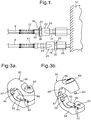
- the invention is particularly applicable in the context of air hoses that are disconnectable from a tractor unit 10, as well as being disconnectable from a trailer unit (not shown) as is conventional.
- the figure shows a tractor unit 10 to which are connected a primary air hose 8 (typically a red hose) and a secondary air hose 9 (which is typically a yellow hose), and which have spiral wire protectors 12 at their ends.
- a primary air hose 8 typically a red hose
- secondary air hose 9 which is typically a yellow hose
- spiral wire protectors 12 at their trailer end (not shown) of the hoses 8 and 9 are conventional couplings: a female primary coupling and a male secondary coupling, which are provided with self-sealing valves to ensure that the hoses 8 and 9 remain sealed when disconnected from the trailer.
- the hoses 8 and 9 are provided, as shown, with similar couplings at the tractor end: the primary air hose 8 is provided with a male coupling 21 while the secondary hose 9 is provided with a female coupling 22.
- the couplings 18 and 19 are connected to the corresponding air lines within the tractor unit 10.
- Each of the female couplings 18 and 22 are of a conventional type, consisting of a generally cylindrical body part 23 respectively, with a sleeve 24.
- the cylindrical body part 23 has at one end an opening into which the corresponding male coupling 19 or 21 can be inserted.
- the sleeve 24 is resiliently biased into the engaged position, as shown, and if the coupling is to be disconnected the sleeve 24 must be slid back along the body part 23 away from the opening; this releases the male coupling 19 or 21, so it can be withdrawn.
- the sleeve 24 must be slid back along the body part 23 away from the opening; this enables the male coupling 19 or 21 to be inserted, and the sleeve 24 is then released so that the coupling is firmly engaged.
- the female couplings 18 and 22 may be identical, or alternatively may be of different sizes.
- each of the female couplings 18 and 22 is provided with a removable lock 30, shown in chain dotted lines, that fits over the body part 23 at the end remote from the opening, and that prevents the sleeve 24 from being slid back sufficiently to release the corresponding male coupling 19 or 21.
- the coupling is itself connected at that end to a component 25 that is of greater width than the body part 23, and the component 25 prevents the lock 30 from being slid off the end of the body part 23.
- a steel washer 36 is connected between the end of the body part 23 and the component 35, and this washer 36 prevents the lock 30 from being slid off the end of the body part 23.
- body part 23 is envisaged as being a separate component from the adjacent component 25, it will be appreciated that in a modification these may be integral with each other. Similarly the washer 36 may form an integral part of the body part 23.
- red hose 38 is provided with a male coupling 41 at the end for connection to the tractor unit 10, and is provided with a female coupling 44 that incorporates a self-sealing valve 45 at the end for connection to the trailer.
- the yellow hose 39 is provided with a female coupling 42 at the end for connection to the tractor unit 10, and is provided with a male coupling 46 that incorporates a self-sealing valve 47 at the end for connection to the trailer.
- the ends for connection to the tractor unit 10 are further distinguished by an oval plastic moulding 50.
- a large washer 36 is provided between the end of the female coupling 42 and the adjacent component of the hose 39 (which is of less width).
- the end portions of the hoses 38 and 39 are provided with plastic reinforcement covers 48.
- the female couplings 42 and 44 each consist of a generally cylindrical body portion 23 that has a pair of opposed flats 51 so that it can be gripped by a spanner during assembly.
- a pin 52 projects from the body portion 23 at a radial position 90° from the flats 51, and the pin 52 can locate in an axial slot 53 in the surrounding sleeve 24.
- the couplings 41 and 42 for connection to the tractor unit 10 may be complementary to the couplings 44 and 46 for connection to the trailer. Alternatively they may be of a different diameter to the couplings 44 and 46 for connection to the trailer; this would ensure that the hoses 38 and 39 cannot be accidentally connected the wrong way round to the wrong airline.
- the lock 30 consists of two arcuate jaws: a lower jaw 55 and an upper jaw 56 which are connected to each other by a pivot pin 57 at one end.
- the opposite ends of the jaws 55 and 56 are secured together (as shown in figure 3a ) by a barrel lock 60 mounted in a recess in the upper jaw 56, the barrel lock 60 having a projecting notched shaft 62 which engages with pins 63 on either side of a recess 64 in the lower jaw 55.
- the barrel lock 60 can be unlocked with a cylindrical key (not shown) which enables the notched shaft 62 to be turned; if turned through 90° from the orientation shown in figure 3b , the end of the notched shaft 62 can fit between the pins 63, and if it is then turned back to the orientation shown in figure 3b the notches on the shaft 62 engage with the pins 63, so the jaws 55 and 56 are secured to each other.
- the key can only be withdrawn when the barrel lock 60 is in its locked orientation, that is to say with the notched shaft 62 in the orientation shown in figure 3b .
- the operation of the lock 30 will be described particularly in the context of attachment to the female coupling 42 on the hose 39 (which corresponds to the female coupling 22 on the hose 9).
- the jaws 55 and 56 When the jaws 55 and 56 are closed together they define a generally cylindrical aperture of diameter slightly larger than that of the body part 23; the lower and upper jaws 55 and 56 meet on a plane that corresponds to a diameter of this aperture.
- the jaws 55 and 56 also define opposed raised flat portions 65, on the far side of the lock 30 as shown, which mate with the flats 51 on the body part 23.
- the jaws 55 and 56 also define two open-ended recesses 66 into which the pin 52 can locate, on either side of the diametral plane, on the near side as shown.
- the lock 30 can be opened, and then the jaws 55 and 56 closed over the body part 23 so that the flat portions 65 engage with the flats 51 and prevent the lock 30 from rotating.
- the projecting pin 52 locates in one or other of the recesses 66.
- the lock 30 is then secured in this position, as shown in figure 1 , preventing the female coupling 42 (or 22) from being released from the adjacent male coupling 19 on the tractor unit 10.
- the washer 36 prevents the lock 30 from being slid off the end of the female coupling 42.
- the lock 30 has been described as being attached to the female coupling 42 on the secondary hose 39, but is equally suitable for use on the female coupling 18 on the tractor unit 10 to which the primary hose 8 (or 38) is connected.
- the connection system as shown in figure 1 , includes the female and male couplings 18 and 19 fixed onto the tractor unit 10; the disconnectable male and female couplings 21 and 22 (or 41 and 42) at the tractor end of the hoses 8 and 9 (or 38 and 39); and the two locks 30 that are locked onto the two female couplings 18 and 22 (or 42) to prevent unauthorised disconnection.
- the lock 30 may be made of any suitable material, desirably one of low density.
- the jaws 55 and 56 may be made of aluminium, or of a plastic.
- the pivot pin 57 and the pins 63 may be of a harder material such as steel.
- the lock 30 is shown only by way of example, and it will be appreciated that it may be modified in various ways while remaining within the scope of the present invention.
- it may incorporate a different lock from the barrel lock 60, and it may have a different external shape.
- the single pivot pin 57 there might instead be a linking element which is itself linked by pivot pins to one end of each of the jaws.
- the jaws might be connected together by mechanisms like the barrel lock 60 at both ends, rather than being pivotally connected at one end.
- the lock might comprise a rigid U-shaped member adapted to fit over the body part 23, the two ends of the U-shaped member connecting with a straight locking element.
- a further alternative mechanism comprises a generally horseshoe-shaped member that can locate adjacent to the end body part, with at least one gripping element that can be slid or pivoted into, and locked in, a position that prevents removal from the end body part.
- the lock 30 there is a washer 36 to prevent the lock 30 from being slid off the end of the body part 23; alternatively or additionally the lock might engage with elements on the body part 23 that prevent it being slid off.
- the recesses 66 are present only on the inner, cylindrical face of the lock 30, and are closed at the end face. In that case the modified lock can be closed so that the pin 52 locates in one of the recesses 66, and since the end face of the recess 66 is closed, the modified lock 30 cannot be slid along the body part 23.
- locks 30 can also be used at the trailer end of the hoses 38 and 39, to prevent unauthorised disconnection of the hoses from the trailer. If the couplings at the trailer end are of a different size to those at the tractor end, then the locks for use at the trailer end would also be of a different size to those at the tractor end. It should, however, be understood that the locks 30 are primarily intended for use at the tractor end, as regulations require that the hoses cannot be unintentionally disconnected from the tractor end. Indeed the locks 30 might be used in an application where the couplings at the tractor end are male and female couplings as described in relation to figure 1 , whereas the couplings at the trailer end are a different type of coupling, such as a gladhand coupling.
Landscapes
- Engineering & Computer Science (AREA)
- General Engineering & Computer Science (AREA)
- Mechanical Engineering (AREA)
- Quick-Acting Or Multi-Walled Pipe Joints (AREA)
Applications Claiming Priority (2)
| Application Number | Priority Date | Filing Date | Title |
|---|---|---|---|
| GB0917618A GB0917618D0 (en) | 2009-10-08 | 2009-10-08 | Hose connector lock |
| PCT/GB2010/051609 WO2011042718A1 (en) | 2009-10-08 | 2010-09-27 | Hose connector lock |
Publications (2)
| Publication Number | Publication Date |
|---|---|
| EP2486320A1 EP2486320A1 (en) | 2012-08-15 |
| EP2486320B1 true EP2486320B1 (en) | 2017-05-31 |
Family
ID=41402716
Family Applications (1)
| Application Number | Title | Priority Date | Filing Date |
|---|---|---|---|
| EP10760398.7A Active EP2486320B1 (en) | 2009-10-08 | 2010-09-27 | Hose connector lock |
Country Status (4)
| Country | Link |
|---|---|
| EP (1) | EP2486320B1 (da) |
| DK (1) | DK2486320T3 (da) |
| GB (1) | GB0917618D0 (da) |
| WO (1) | WO2011042718A1 (da) |
Families Citing this family (2)
| Publication number | Priority date | Publication date | Assignee | Title |
|---|---|---|---|---|
| KR102084874B1 (ko) * | 2016-01-08 | 2020-03-04 | 바르실라 핀랜드 오이 | 파이프 조립체 및 파이프 조립체의 연결 방법 |
| US12553557B2 (en) * | 2022-02-07 | 2026-02-17 | Trackmobile Llc | Air hose coupling in automated gladhand system |
Family Cites Families (7)
| Publication number | Priority date | Publication date | Assignee | Title |
|---|---|---|---|---|
| US2565659A (en) * | 1949-02-21 | 1951-08-28 | George S Kontra | Speedometer cable fitting lock |
| US3359015A (en) * | 1965-06-14 | 1967-12-19 | Crawford Fitting Co | Quick connect tube coupling |
| US5066049A (en) * | 1990-11-13 | 1991-11-19 | Parker Hannifin Corporation | Lockout device for hose fitting |
| JP2560248Y2 (ja) * | 1992-11-26 | 1998-01-21 | 日東工器株式会社 | 管継手 |
| US5462316A (en) * | 1994-05-19 | 1995-10-31 | Campbell Fittings, Inc. | Quick action fluid coupling |
| US6612619B2 (en) * | 1999-01-05 | 2003-09-02 | Martin H. Wieder | Quick coupler retention clip and method |
| CA2600573A1 (en) * | 2006-09-01 | 2008-03-01 | Garry Draper | Split ring assembly to lock a cam pipe coupling |
-
2009
- 2009-10-08 GB GB0917618A patent/GB0917618D0/en not_active Ceased
-
2010
- 2010-09-27 EP EP10760398.7A patent/EP2486320B1/en active Active
- 2010-09-27 WO PCT/GB2010/051609 patent/WO2011042718A1/en not_active Ceased
- 2010-09-27 DK DK10760398.7T patent/DK2486320T3/da active
Also Published As
| Publication number | Publication date |
|---|---|
| WO2011042718A1 (en) | 2011-04-14 |
| GB0917618D0 (en) | 2009-11-25 |
| EP2486320A1 (en) | 2012-08-15 |
| DK2486320T3 (da) | 2017-09-18 |
Similar Documents
| Publication | Publication Date | Title |
|---|---|---|
| US8876169B2 (en) | Cam-lock actuating device for use in a locking coupling assembly that couples two tubular members | |
| AU732138B2 (en) | Pivotal lock for coupling cam arms | |
| US4802694A (en) | Quick-disconnect coupling | |
| US5863079A (en) | Quick connect/disconnect coupling | |
| EP0314381B1 (en) | Coupling with lock indicator | |
| US5896889A (en) | Quick-set hydraulic coupler | |
| MXPA03007290A (es) | Obturador de acoplamiento de fluido. | |
| EP2486320B1 (en) | Hose connector lock | |
| US5026099A (en) | Dry break coupler with ring collar sleeve operator | |
| US20170363239A1 (en) | Quick Connector | |
| US20110133430A1 (en) | Air brake connection system | |
| CA2461826C (en) | Pipe coupler | |
| EP1030993B1 (en) | Quick-action coupling | |
| US11867328B2 (en) | Plug-in connection system for fluid-conducting components, in particular of fire extinguishing systems, and component parts of said connection system | |
| EP2220416B1 (en) | Cap for a fluid coupling member | |
| EP2636935B1 (en) | Cam-lock actuating device for use in a locking coupling assembly that couples two tubular members. | |
| EP3507533B1 (en) | Safety cam lock fitting and method | |
| EP0885364B1 (en) | Quick connect/disconnect coupling | |
| US5310161A (en) | High pressure gas line breakaway connector | |
| CN219339121U (zh) | 一种拖车钩总成及车辆 | |
| WO2024101142A1 (ja) | 管継手部材 | |
| CA2249297C (en) | Quick connect/disconnect coupling | |
| AU2012200762B2 (en) | Cam-lock actuating device for use in a locking coupling assembly that couples two tubular members | |
| IL126304A (en) | Quick coupling | |
| WO2003089831A1 (en) | Releasable coupling |
Legal Events
| Date | Code | Title | Description |
|---|---|---|---|
| PUAI | Public reference made under article 153(3) epc to a published international application that has entered the european phase |
Free format text: ORIGINAL CODE: 0009012 |
|
| 17P | Request for examination filed |
Effective date: 20120418 |
|
| AK | Designated contracting states |
Kind code of ref document: A1 Designated state(s): AL AT BE BG CH CY CZ DE DK EE ES FI FR GB GR HR HU IE IS IT LI LT LU LV MC MK MT NL NO PL PT RO SE SI SK SM TR |
|
| DAX | Request for extension of the european patent (deleted) | ||
| 17Q | First examination report despatched |
Effective date: 20150911 |
|
| GRAP | Despatch of communication of intention to grant a patent |
Free format text: ORIGINAL CODE: EPIDOSNIGR1 |
|
| INTG | Intention to grant announced |
Effective date: 20170105 |
|
| GRAS | Grant fee paid |
Free format text: ORIGINAL CODE: EPIDOSNIGR3 |
|
| GRAA | (expected) grant |
Free format text: ORIGINAL CODE: 0009210 |
|
| AK | Designated contracting states |
Kind code of ref document: B1 Designated state(s): AL AT BE BG CH CY CZ DE DK EE ES FI FR GB GR HR HU IE IS IT LI LT LU LV MC MK MT NL NO PL PT RO SE SI SK SM TR |
|
| REG | Reference to a national code |
Ref country code: CH Ref legal event code: EP Ref country code: GB Ref legal event code: FG4D |
|
| REG | Reference to a national code |
Ref country code: AT Ref legal event code: REF Ref document number: 897809 Country of ref document: AT Kind code of ref document: T Effective date: 20170615 |
|
| REG | Reference to a national code |
Ref country code: IE Ref legal event code: FG4D |
|
| REG | Reference to a national code |
Ref country code: DE Ref legal event code: R096 Ref document number: 602010042691 Country of ref document: DE |
|
| REG | Reference to a national code |
Ref country code: NL Ref legal event code: FP |
|
| REG | Reference to a national code |
Ref country code: NO Ref legal event code: T2 Effective date: 20170531 |
|
| REG | Reference to a national code |
Ref country code: SE Ref legal event code: TRGR |
|
| REG | Reference to a national code |
Ref country code: DK Ref legal event code: T3 Effective date: 20170911 |
|
| REG | Reference to a national code |
Ref country code: FR Ref legal event code: PLFP Year of fee payment: 8 |
|
| REG | Reference to a national code |
Ref country code: LT Ref legal event code: MG4D |
|
| REG | Reference to a national code |
Ref country code: AT Ref legal event code: MK05 Ref document number: 897809 Country of ref document: AT Kind code of ref document: T Effective date: 20170531 |
|
| PG25 | Lapsed in a contracting state [announced via postgrant information from national office to epo] |
Ref country code: ES Free format text: LAPSE BECAUSE OF FAILURE TO SUBMIT A TRANSLATION OF THE DESCRIPTION OR TO PAY THE FEE WITHIN THE PRESCRIBED TIME-LIMIT Effective date: 20170531 Ref country code: GR Free format text: LAPSE BECAUSE OF FAILURE TO SUBMIT A TRANSLATION OF THE DESCRIPTION OR TO PAY THE FEE WITHIN THE PRESCRIBED TIME-LIMIT Effective date: 20170901 Ref country code: FI Free format text: LAPSE BECAUSE OF FAILURE TO SUBMIT A TRANSLATION OF THE DESCRIPTION OR TO PAY THE FEE WITHIN THE PRESCRIBED TIME-LIMIT Effective date: 20170531 Ref country code: HR Free format text: LAPSE BECAUSE OF FAILURE TO SUBMIT A TRANSLATION OF THE DESCRIPTION OR TO PAY THE FEE WITHIN THE PRESCRIBED TIME-LIMIT Effective date: 20170531 Ref country code: AT Free format text: LAPSE BECAUSE OF FAILURE TO SUBMIT A TRANSLATION OF THE DESCRIPTION OR TO PAY THE FEE WITHIN THE PRESCRIBED TIME-LIMIT Effective date: 20170531 Ref country code: LT Free format text: LAPSE BECAUSE OF FAILURE TO SUBMIT A TRANSLATION OF THE DESCRIPTION OR TO PAY THE FEE WITHIN THE PRESCRIBED TIME-LIMIT Effective date: 20170531 |
|
| PG25 | Lapsed in a contracting state [announced via postgrant information from national office to epo] |
Ref country code: IS Free format text: LAPSE BECAUSE OF FAILURE TO SUBMIT A TRANSLATION OF THE DESCRIPTION OR TO PAY THE FEE WITHIN THE PRESCRIBED TIME-LIMIT Effective date: 20170930 Ref country code: BG Free format text: LAPSE BECAUSE OF FAILURE TO SUBMIT A TRANSLATION OF THE DESCRIPTION OR TO PAY THE FEE WITHIN THE PRESCRIBED TIME-LIMIT Effective date: 20170831 Ref country code: LV Free format text: LAPSE BECAUSE OF FAILURE TO SUBMIT A TRANSLATION OF THE DESCRIPTION OR TO PAY THE FEE WITHIN THE PRESCRIBED TIME-LIMIT Effective date: 20170531 |
|
| PG25 | Lapsed in a contracting state [announced via postgrant information from national office to epo] |
Ref country code: CZ Free format text: LAPSE BECAUSE OF FAILURE TO SUBMIT A TRANSLATION OF THE DESCRIPTION OR TO PAY THE FEE WITHIN THE PRESCRIBED TIME-LIMIT Effective date: 20170531 Ref country code: SK Free format text: LAPSE BECAUSE OF FAILURE TO SUBMIT A TRANSLATION OF THE DESCRIPTION OR TO PAY THE FEE WITHIN THE PRESCRIBED TIME-LIMIT Effective date: 20170531 Ref country code: RO Free format text: LAPSE BECAUSE OF FAILURE TO SUBMIT A TRANSLATION OF THE DESCRIPTION OR TO PAY THE FEE WITHIN THE PRESCRIBED TIME-LIMIT Effective date: 20170531 Ref country code: EE Free format text: LAPSE BECAUSE OF FAILURE TO SUBMIT A TRANSLATION OF THE DESCRIPTION OR TO PAY THE FEE WITHIN THE PRESCRIBED TIME-LIMIT Effective date: 20170531 |
|
| PG25 | Lapsed in a contracting state [announced via postgrant information from national office to epo] |
Ref country code: SM Free format text: LAPSE BECAUSE OF FAILURE TO SUBMIT A TRANSLATION OF THE DESCRIPTION OR TO PAY THE FEE WITHIN THE PRESCRIBED TIME-LIMIT Effective date: 20170531 Ref country code: PL Free format text: LAPSE BECAUSE OF FAILURE TO SUBMIT A TRANSLATION OF THE DESCRIPTION OR TO PAY THE FEE WITHIN THE PRESCRIBED TIME-LIMIT Effective date: 20170531 |
|
| REG | Reference to a national code |
Ref country code: DE Ref legal event code: R097 Ref document number: 602010042691 Country of ref document: DE |
|
| PLBE | No opposition filed within time limit |
Free format text: ORIGINAL CODE: 0009261 |
|
| STAA | Information on the status of an ep patent application or granted ep patent |
Free format text: STATUS: NO OPPOSITION FILED WITHIN TIME LIMIT |
|
| REG | Reference to a national code |
Ref country code: CH Ref legal event code: PL |
|
| 26N | No opposition filed |
Effective date: 20180301 |
|
| PG25 | Lapsed in a contracting state [announced via postgrant information from national office to epo] |
Ref country code: MC Free format text: LAPSE BECAUSE OF FAILURE TO SUBMIT A TRANSLATION OF THE DESCRIPTION OR TO PAY THE FEE WITHIN THE PRESCRIBED TIME-LIMIT Effective date: 20170531 Ref country code: SI Free format text: LAPSE BECAUSE OF FAILURE TO SUBMIT A TRANSLATION OF THE DESCRIPTION OR TO PAY THE FEE WITHIN THE PRESCRIBED TIME-LIMIT Effective date: 20170531 |
|
| PG25 | Lapsed in a contracting state [announced via postgrant information from national office to epo] |
Ref country code: LU Free format text: LAPSE BECAUSE OF NON-PAYMENT OF DUE FEES Effective date: 20170927 |
|
| PG25 | Lapsed in a contracting state [announced via postgrant information from national office to epo] |
Ref country code: LI Free format text: LAPSE BECAUSE OF NON-PAYMENT OF DUE FEES Effective date: 20170930 Ref country code: CH Free format text: LAPSE BECAUSE OF NON-PAYMENT OF DUE FEES Effective date: 20170930 |
|
| REG | Reference to a national code |
Ref country code: FR Ref legal event code: PLFP Year of fee payment: 9 |
|
| PG25 | Lapsed in a contracting state [announced via postgrant information from national office to epo] |
Ref country code: MT Free format text: LAPSE BECAUSE OF NON-PAYMENT OF DUE FEES Effective date: 20170927 |
|
| PG25 | Lapsed in a contracting state [announced via postgrant information from national office to epo] |
Ref country code: HU Free format text: LAPSE BECAUSE OF FAILURE TO SUBMIT A TRANSLATION OF THE DESCRIPTION OR TO PAY THE FEE WITHIN THE PRESCRIBED TIME-LIMIT; INVALID AB INITIO Effective date: 20100927 |
|
| PG25 | Lapsed in a contracting state [announced via postgrant information from national office to epo] |
Ref country code: CY Free format text: LAPSE BECAUSE OF NON-PAYMENT OF DUE FEES Effective date: 20170531 |
|
| PGFP | Annual fee paid to national office [announced via postgrant information from national office to epo] |
Ref country code: IE Payment date: 20190920 Year of fee payment: 10 Ref country code: IT Payment date: 20190920 Year of fee payment: 10 Ref country code: FR Payment date: 20190925 Year of fee payment: 10 |
|
| PG25 | Lapsed in a contracting state [announced via postgrant information from national office to epo] |
Ref country code: MK Free format text: LAPSE BECAUSE OF FAILURE TO SUBMIT A TRANSLATION OF THE DESCRIPTION OR TO PAY THE FEE WITHIN THE PRESCRIBED TIME-LIMIT Effective date: 20170531 |
|
| PGFP | Annual fee paid to national office [announced via postgrant information from national office to epo] |
Ref country code: BE Payment date: 20190924 Year of fee payment: 10 |
|
| PG25 | Lapsed in a contracting state [announced via postgrant information from national office to epo] |
Ref country code: TR Free format text: LAPSE BECAUSE OF FAILURE TO SUBMIT A TRANSLATION OF THE DESCRIPTION OR TO PAY THE FEE WITHIN THE PRESCRIBED TIME-LIMIT Effective date: 20170531 |
|
| PG25 | Lapsed in a contracting state [announced via postgrant information from national office to epo] |
Ref country code: PT Free format text: LAPSE BECAUSE OF FAILURE TO SUBMIT A TRANSLATION OF THE DESCRIPTION OR TO PAY THE FEE WITHIN THE PRESCRIBED TIME-LIMIT Effective date: 20170531 |
|
| PG25 | Lapsed in a contracting state [announced via postgrant information from national office to epo] |
Ref country code: AL Free format text: LAPSE BECAUSE OF FAILURE TO SUBMIT A TRANSLATION OF THE DESCRIPTION OR TO PAY THE FEE WITHIN THE PRESCRIBED TIME-LIMIT Effective date: 20170531 |
|
| REG | Reference to a national code |
Ref country code: BE Ref legal event code: MM Effective date: 20200930 |
|
| PG25 | Lapsed in a contracting state [announced via postgrant information from national office to epo] |
Ref country code: FR Free format text: LAPSE BECAUSE OF NON-PAYMENT OF DUE FEES Effective date: 20200930 |
|
| PG25 | Lapsed in a contracting state [announced via postgrant information from national office to epo] |
Ref country code: IE Free format text: LAPSE BECAUSE OF NON-PAYMENT OF DUE FEES Effective date: 20200927 Ref country code: BE Free format text: LAPSE BECAUSE OF NON-PAYMENT OF DUE FEES Effective date: 20200930 |
|
| PG25 | Lapsed in a contracting state [announced via postgrant information from national office to epo] |
Ref country code: IT Free format text: LAPSE BECAUSE OF NON-PAYMENT OF DUE FEES Effective date: 20200927 |
|
| REG | Reference to a national code |
Ref country code: GB Ref legal event code: 732E Free format text: REGISTERED BETWEEN 20231102 AND 20231108 |
|
| REG | Reference to a national code |
Ref country code: DE Ref legal event code: R081 Ref document number: 602010042691 Country of ref document: DE Owner name: MORRIS, COLIN ANTHONY, GB Free format text: FORMER OWNER: CM ENGINEERING CONSULTANTS LTD., MALVERN, WORCESTERSHIRE, GB |
|
| REG | Reference to a national code |
Ref country code: NL Ref legal event code: PD Owner name: COLIN ANTHONY MORRIS; GB Free format text: DETAILS ASSIGNMENT: CHANGE OF OWNER(S), ASSIGNMENT; FORMER OWNER NAME: CM ENGINEERING CONSULTANTS LIMITED Effective date: 20240809 |
|
| PGFP | Annual fee paid to national office [announced via postgrant information from national office to epo] |
Ref country code: DK Payment date: 20250910 Year of fee payment: 16 Ref country code: DE Payment date: 20250822 Year of fee payment: 16 |
|
| PGFP | Annual fee paid to national office [announced via postgrant information from national office to epo] |
Ref country code: NO Payment date: 20250922 Year of fee payment: 16 |
|
| PGFP | Annual fee paid to national office [announced via postgrant information from national office to epo] |
Ref country code: NL Payment date: 20250918 Year of fee payment: 16 |
|
| PGFP | Annual fee paid to national office [announced via postgrant information from national office to epo] |
Ref country code: GB Payment date: 20250822 Year of fee payment: 16 |
|
| PGFP | Annual fee paid to national office [announced via postgrant information from national office to epo] |
Ref country code: SE Payment date: 20250821 Year of fee payment: 16 |