EP2486316B1 - A tool for a horizontal connecting device - Google Patents
A tool for a horizontal connecting device Download PDFInfo
- Publication number
- EP2486316B1 EP2486316B1 EP10822289.4A EP10822289A EP2486316B1 EP 2486316 B1 EP2486316 B1 EP 2486316B1 EP 10822289 A EP10822289 A EP 10822289A EP 2486316 B1 EP2486316 B1 EP 2486316B1
- Authority
- EP
- European Patent Office
- Prior art keywords
- connecting part
- tool
- lifting frame
- tool according
- module
- Prior art date
- Legal status (The legal status is an assumption and is not a legal conclusion. Google has not performed a legal analysis and makes no representation as to the accuracy of the status listed.)
- Active
Links
Images





Classifications
-
- E—FIXED CONSTRUCTIONS
- E21—EARTH OR ROCK DRILLING; MINING
- E21B—EARTH OR ROCK DRILLING; OBTAINING OIL, GAS, WATER, SOLUBLE OR MELTABLE MATERIALS OR A SLURRY OF MINERALS FROM WELLS
- E21B43/00—Methods or apparatus for obtaining oil, gas, water, soluble or meltable materials or a slurry of minerals from wells
- E21B43/01—Methods or apparatus for obtaining oil, gas, water, soluble or meltable materials or a slurry of minerals from wells specially adapted for obtaining from underwater installations
- E21B43/0107—Connecting of flow lines to offshore structures
-
- F—MECHANICAL ENGINEERING; LIGHTING; HEATING; WEAPONS; BLASTING
- F16—ENGINEERING ELEMENTS AND UNITS; GENERAL MEASURES FOR PRODUCING AND MAINTAINING EFFECTIVE FUNCTIONING OF MACHINES OR INSTALLATIONS; THERMAL INSULATION IN GENERAL
- F16L—PIPES; JOINTS OR FITTINGS FOR PIPES; SUPPORTS FOR PIPES, CABLES OR PROTECTIVE TUBING; MEANS FOR THERMAL INSULATION IN GENERAL
- F16L1/00—Laying or reclaiming pipes; Repairing or joining pipes on or under water
- F16L1/26—Repairing or joining pipes on or under water
Definitions
- the present invention relates to a tool for lowering, alternatively later retrieval, of a pipeline end provided with a connecting part designed for "horizontal” mating with and connection to a first connecting part on the sea bed, and is so arranged that the tool can be brought to the surface again for reuse.
- the tool is in particular developed with a view to deploy on the seabed a connecting device of the type described in Norwegian Patent Application NO 2009 3107 having the same applicant and inventor as in the present application. Reference is hereby given to that patent application.
- horizontal connecting device has that meaning that the connecting parts are mated in a substantially horizontal direction.
- piping is often arranged thereon having one or more pipes that terminate in open pipe subs, or porches, forming a connecting point.
- Each connecting point includes a stationary connecting part.
- “Stationary" means relative to the subsea structure.
- the connecting point is later used for connection to an external pipe.
- connecting devices either vertical or horizontal.
- the connecting point projects horizontally out from the structure.
- this solution almost has market control.
- Other places, like the Gulf of Mexico for example, the vertical solution is the most common one.
- One example of a vertical connecting device is shown in NO 2009 2880 .
- Publication GB2440336 relates to the vertical connection principle where the connection point projects vertically in relation to the seabed.
- Publication WO0179736 discloses a pull-in tool and a collar used for connecting of a fixed coupling head and a termination head together at the seabed.
- the coupling head and the termination head are deployed to the seabed prior to the connection of the pull in tool and the collar to the coupling head and the termination head.
- Publication US5458439 discloses a pipe attachment and receiving apparatus for severing and handling a subsea pipe.
- the apparatus including a chassis adapted to mount onto a subsea pipeline.
- a cutting module is mounted to the interface assembly to repair the pipeline with a replacement spool.
- the tool according to the invention has several main components and is such designed in one embodiment that each main component is in the form of a replaceable module.
- the tool can be used to deploy both a first and a second end of a flexible pipeline, yet after having made some modifications on the tool.
- the problems to be addressed can be somewhat different when the first end is to be laid from a surface vessel and down to the seabed compared with deployment of the second end.
- a tool of the introductory said kind is provided, which tool is distinguished in that the tool comprises a central lifting frame, a guiding part forming an extension of the lifting frame, and a lifting yoke having rods pivotally connected to the lifting frame via axle pins, said tool comprises gripping mechanisms being actuatable to partly circumscribe and retain the pipeline end when lowering or retrieving the pipeline end relative the seabed, and releasable to release the pipeline end from the lifting frame when the tool is to be brought to the surface for reuse, said guiding part comprising a bail structure configured to mate with an upwardly projection Y-structure of the first connecting part when lowered to towards the seabed.
- the tool preferably comprises additional features, as defined in the dependent claims.
- Figure 1 shows the tool 20 as the tool appears alone when not in use, i.e. that no pipe end is present in the tool 20.
- a tool is used to lower a pipeline end to the seabed.
- Pipelines for this purpose terminates in a connecting part 2 that can be clearest seen in fig. 6 .
- This connecting part 2 is to be guided towards a first connecting part 1, which already has been put down onto the seabed, to be able to make a connection between the connecting parts 1 and 2. After that the connecting operation is completed, the tool 20 is allowed to be brought to the surface again for later use.
- the tool 20 includes a central lifting frame 30 which is able to retain, or support, a pipe end E 2 (not shown in fig.1 and 2 , but 3).
- a lifting yoke 50 is connected to the lifting frame 30.
- the lifting yoke 50 includes two rods that are pivotable connected to the lifting frame 30 via axle pins 31.
- the lifting yoke 50 has a limited freedom of motion to pivot about the axle pins 31.
- the limitation is set by two straps 53, or wires, that respectively extends between a shackle 54 at the top of the lifting yoke 50 and a shackle 45 secured in a padeye 44 of a control (guide) part 40.
- the control part 40 forms an extension of the lifting frame 30.
- control part 40 The function of the control part 40 and the mode of operation thereof are explained in closer detail in connection with the figures 6-8 when the tool 20 is used with a connecting part.
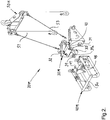
- FIG. 2 shows the same tool as in figure 1 , now however, subdivided into modules, which will be convenient on many situations. This is explained at the very end of this specification.
- the modularly constructed tool 20M is assembled of a central lifting frame module 30M, a control module 40M releasable from the lifting frame module 30M and forms an extension of the lifting frame module 30M, and a lifting yoke module 50M releasable from the lifting frame module 30M. Otherwise, the remaining components are as before and have the same reference numbers as in figure 1 .
- the tool 20, 20M includes gripping mechanisms, which in a first situation can be activated to partly enclose and retain the pipeline end E 2 . In a second situation, the gripping mechanisms can be released such that the pipeline end E 2 is released from the tool 20, 20M, typically when the tool 20, 20M is to be recovered to the surface.
- the gripping mechanism is releasable from the pipeline end E 2 by operating actuation means 32.
- the actuation means 32 are entirely specific located and arranged such that they are easy accessible from above.
- the actuation means 32 are preferably operated by a remote-controlled vessel (ROV), and is very easily operated from above.
- ROV remote-controlled vessel
- each gripping mechanism includes a pawl 33 which is pivotable arranged to the lifting frame 30, 30M.
- the pawl 33 is influenced by the actuation means 32.
- the lower end of the actuation means 32 acts against an inclined surface 34 of the pawl 33 in order to effect the pivotal motion of the pawl 33.
- two hooks 46 are arranged, which in a quick release way are designed to cooperate with an axle pin 39a extending through holes in support brackets 39 of the lifting frame module 30M. Then the control module 40M can be hooked onto the lifting frame module 30M via the hooks 46 and the axle pins 39a, and be locked to each other by means of quick operated lock pins 41.
- Figure 3 shows in elevation view and partly in cross section, the tool 20, 20M and a connecting part 2 retained in the tool.
- the connecting part 2 retains securely the pipe end E 2 , and a connector 3 is standby ready for later connection. A more complete description is given later together with figure 6 .
- the tool 20M as an entirety, alternatively the control module 40M alone, can be released from/alternatively connected to the connecting part 2.
- the control module 40M includes a lug or catch lever 43 that cooperates with a cutout or notch 23 arranged on the connecting part 2.
- the lug 43 and the notch 23 cooperate to securely retain the connecting part 2 to the control module 40M, yet with some freedom of motion.
- Fig. 2 shows a screw 47 that can be turned in and out. In that end facing forwards in figure 2 , the screw is free of threads and is designed to be screwed as a plug into a hole 24 in an end plate 9 of the connecting part 2, see figure 6 .
- An alternative to the screw 47 can be a bayonet locking mechanism, which is a still more rapid locking mechanism.
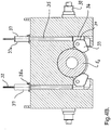
- Figure 4A and 4B shows in closer detail the gripping mechanisms and associated actuation means 32 and pawls 33.
- Fig. 4A shows the pawls 33 in open position, i.e. in a position where a pipe end E 2 can be brought up and into the lifting frame 30, alternatively be released therefrom.
- Fig. 4B shows the pawls in closed position, i.e. in a position where the pipe end E 2 is fixedly retained in the lifting frame 30.
- the inclined surface 34 that the actuation means 32 acts against is also indicated.
- the actuation means 32 is here shown in the form of an actuation rod 35 having a lower end in the form of a mandrel body 36 that acts against the inclined surface 34 of the pawl 33.
- a bayonet locking mechanism is arranged in the upper end of the actuation rod 35.
- the bayonet locking mechanism includes a sleeve part 37, having coulisse guides 37a, which id fixedly secured to the lifting frame 30, 30M. It further includes a mandrel part 38 having a projecting pin 38a which follows the coulisse guide 37a.
- the coulisse guide 37a can be a J-slot.
- the operation of the bayonet locking mechanism takes place in that the actuation means 32 is influenced by a ROV that turns the means 32 in a quarter to half a revolution at the same time as the rod 35 is pushed down. This locks the pipe end E 2 to the lifting frame 30, 30M.
- the pawl 33 is self-releasable in the sense that when the rod 35 is elevated, the pawl is pivoting down by virtue of its own weight and thus opens for release from the pipe end E 2 .
- the actuation rod can be a screw rod which is threaded and extends through a sleeve body (corresponding to the sleeve part 37) which is equipped with internal threads which allows the rod to be screwed up and down in order to act on the pawl 33.
- the above described gripping mechanisms are mechanical solutions that are very sturdy and reliable in order to be fully failsafe. It is also to be explained that the locking mechanism is such designed that the high load forces extend right through the lock pawl and vertical rod 35 out to the lifting frame itself. Thereby one avoids that the loads extend up to the interface with the ROV, which enables the ROV to operate with small forces.
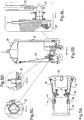
- Fig. 5A shows the tool 20, 20M from above including a cross section line A-A (not rectilinear).
- the sections are to show different details of the tool 20, 20M. These details shall for example show that the control module 40M is releasable from the lifting frame module 30M by means of quick release means, here shown in the form of the lock pin 41, or a cotter pin. See fig. 5A and 5D (Detail C). This in combination with the hooks 46 described above in connection with figure 2 .
- the lifting yoke module 50M is in turn releasable from the lifting frame module 30M by means of quick release means, such as cotter pins (not shown) at the end of the axle pins 31, to which the rods 51 are attached, and snap hooks 56 at the end of the straps 53 for attachment to the shackles 45 etc.
- quick release means such as cotter pins (not shown) at the end of the axle pins 31, to which the rods 51 are attached, and snap hooks 56 at the end of the straps 53 for attachment to the shackles 45 etc.
- Fig. 5C shows a lock pin or cotter pin 42 for adjustment of a dampening effect that can be arranged in the control part 40. As indicated, three different positions (holes) exist into which one or more pins 42 can be put.
- FIG 6 shows a complete connecting device 10 to which the tool 20, 20M is designed.
- the connecting device 10 is as previously mentioned assembled by a first connecting part 1, a second connecting part 2 and a ramp structure 6.
- the first connecting part 1 is secured to a subsea structure (not shown), such as a manifold structure or a Christmas tree structure.
- the first connecting part 1 can be considered as stationary relative to the subsea structure.
- the first connecting part 1 is such arranged that it supports, or retains, the end E 1 of a first pipeline, which then will be located within the subsea structure. It is to be understood that the first connecting part 1 and the first pipeline will firstly be landed on the seabed (together with the subsea structure).
- the first connecting part 1 includes a control structure 4 located some distance apart from the pipe end E 1 .
- the second connecting part 2 is to be lowered from the surface in a direction towards the subsea structure, more precisely towards the first connecting part 1.
- the second connecting part 2 can be considered as mobile relative to the subsea structure.
- the second connecting part 2 is such arranged that it retains the end E 2 of a second pipeline.
- the second connecting part 2 is moved by means of the tool 20, 20M described above.
- the ramp structure 6 is located close to or adjacent to the first connecting part 1.
- the ramp structure 6 has a major function when the connecting parts 1, 2 are to be mated, and possibly at later occasions if disconnection is to be made.
- the ramp structure 6 is equipped with abutment surfaces and guiding means which are designed for engagement with cooperating surfaces and means on the second connecting part 2 when the second connecting part 2 is advanced towards the first connecting part 1. When this is performed fine alignment between the pipe ends E 1 , E 2 is achieved.
- a connector 3 is arranged on one of the connecting parts 1, 2, here shown on the second connecting part 2. After that the pipe ends E 1 , E 2 are fine aligned with each other and pulled together until contact flange to flange, possibly with a seal therebetween, the connector 3 is activated and makes final, lasting connection between the pipe ends E 1 , E 2 .
- the connector 3 is operated by a ROV that turns a threaded bolt 3a on the connector 3.
- the connector 3 will normally be of that type clamp connector having internally arranged, annular inclined surfaces, which by activation forces two pipe flanges axially towards each other.
- One of the pipe flanges has a sealing ring installed thereon having externally arranged, annular inclined surfaces.
- the connector can be of the type "collet connector”.
- the ramp structure 6, in a preferred embodiment, is physically separated from the first connecting part 1. Then the second connecting part 2 can at desire, be parked on the ramp structure 6 after that a disconnecting operation between the connecting parts 1, 2 has been made. Then the subsea structure, which the first connecting part 1 is part of, can be recovered to the surface. Normally there are many such first and second connecting parts 1, 2 for each subsea structure and, as one will understand, all the second connecting parts 2 will remain parked on the ramp structure 6 on the seabed when the subsea structures need to be recovered to the surface for maintenance, modifications, repair, etc.
- the described physical separation is, however, not necessarily totally definite.
- the guiding means of the ramp structure 6 are designed and shown as a projecting plate part 6a in the area adjacent to the first connecting part 1, as shown on the figures.
- the cooperating means of the second connecting part 2 are designed and shown as an incision 2a, or a notch. Then it is to be understood that the projecting plate part 6a on the ramp structure 6 becomes in slidable engagement with the incision 2a when the pipe ends E 1 , E 2 are moved towards each other in the terminating phase of the mating operation. When they are in complete engagement such prevents any tilting motion of the second connecting part 2 relative to the first connecting part 1.
- the abutment, or contact surfaces of the ramp structure 6 can in turn include ramp surfaces as suggested by the reference number 6b.
- the second connecting part 2 has contact surfaces 2b that cooperate with the ramp surfaces 6b when the second connecting part 2 is moved towards the first connecting part 1.
- inclined surfaces 6c are arranged, which surfaces terminate in a straight edge 6d down to the ramp structure 6.
- This inclined surface 6c is functioning to control the second connecting part 2, via the contact surfaces 2b, down to a base surface 6e on the top side of the ramp structure.
- the contact surfaces 2b really has arrived at and in contact with the base surfaces 6e, the second connecting part 2 is prevented from unintentional motion rearwards due to the straight stop edge 6d.
- a smaller edge 6f is arranged at the front end of the base surface 6e. This edge 6f has the important function to be able to prevent the connecting part 2 from sliding in an uncontrolled way towards the connecting part 1, i.e.
- the second connecting part 2 rests in peace on the base surfaces 6e due to it own weight.
- the first connecting part 1 consist of a rear plate 7 and a front plate 8.
- the front plate 8 supports the first pipe end E 1 .
- a plurality of braces is arranged between the rear plate 7 and front plate 8 in per se known manner.
- the front plate 8 has at least one adapted mounting 8a in the form of a U-shaped recess which is designed for insertion of the pull/push tool.
- the front plate 8 includes at least one control pin 8b, here shown two in number, which are located in the lower portion of the front plate 8 and are pointing in a direction towards the second connecting part 2.
- the second connecting part 2 consist of a main plate 9 that supports the second pipe end E 2 .
- a plurality of tubular braces are perpendicular located on the main plate 9 and the lower hollow braces 9b simultaneously constitute guiding means in the form of a female part that is to cooperate with the above described control pin 8b during the finishing part of the mating operation of the connecting parts 1, 2.
- the main plate 9 also have at least one adapted mount 9a in the form of a U-shaped recess or cut-out, which is designed for insertion of the above described pull/push tool.
- first connecting plate 9c is rigidly connected between the hollow braces 9b in that end facing toward the first connecting part 1
- a second connecting plate 9d is rigidly connected between the hollow braces 9b in that end facing away from the first connecting part 1.
- the first connecting plate 9c includes the previously described incisions 2a, or notches, that cooperate with the plate edges 6a on the ramp structure 6, i.e. more precisely those plate parts 6a that are facing inwardly of the ramp structure 6.
- the second connecting plate 9d includes the previously described contact surfaces 2b that in sequence cooperate firstly with the inclined surfaces 6c, then the base surface 6e and the stop edges 6d and 6f of the ramp structure 6, before the contact surfaces 2b start to ride on the ramp surfaces 6b during last phase of the mating operation.
- control structure 4 consists of an upwardly projecting frame structure 4a in two parts standing like a "Y" relative to each other and that are able to receive a corresponding control module 40M, which is arranged on the second connecting part 2 in the form of a removable tool 20.
- the control module 40M of the second connecting part 2 consists of a projecting bail structure 5a which, in an initial phase, in a sliding manner cooperates with the upwards projecting frame structure 4a of the first connecting part 1.
- the second connecting part 2 is forced to pivot till abutment against the ramp structure 6.
- the projecting bail structure 5a of the second connecting part 2 can, as mentioned, preferably be in the form of a tool that is releasable arranged and can be recovered to the surface after that the connection is made up.
- Fig. 7 shows the complete tool 20, 20M that carries along the second connecting part 2 which in turn supports the pipe end E 2 .
- Fig. 8A to 8H show sequences of the mating operation that takes place between the connecting parts 1, 2 and by use of the ramp structure 6 as assisting means.
- Fig. 8A shows that the second connecting part 2 is lowered from the surface, for example from a surface vessel.
- the second connecting part 2 is designed to land on the ramp structure 6 as described above.
- Fig. 8B shows that moment when the second connecting part 2 hits the first connecting part 1, in that the bail structure 5a hits the Y-configured, upwardly facing mouth of the frame structure 4a.
- Fig. 8C shows that moment when the bail structure 5a bottoms in the frame structure 4a and starts to pivot towards the ramp structure 6 about a pivot point which is exactly located in the bottom of the frame structure 4a.
- Fig. 8D shows that moment when the second connecting part 2 is landing on the ramp structure 6 and is controlled in by means of the inclined surfaces 6c. This is also that situation when the incisions 2a are controlled in and over the plate parts 6a in order to make engagement with each other.
- Fig. 8E shows first intermediate position before final connection is made. Now the contact surfaces 2b stand resting against the base surfaces 6e and are prevented by the stop edge 6d from rearward movement. The notches 2a are advanced to engagement with the plate parts 6a and prevent tilting motion as previously described.
- Fig. 8F shows the same situation for the connecting device 10 as fig. 8E , but the installation tool 20 is removed and recovered to the surface for later use. When the tool 20 is removed, it is the edge 6f that prevents forward motion.
- Fig. 8G shows the situation that the second connecting part 2 has been pulled toward the first connecting part 1 by means of the pull/push tool (not shown).
- the contact surfaces 2b has started to climb onto the ramp surfaces 6b and tilt the second pipe end E 2 upwards.
- Fig. 8H shows the situation when the second connecting part 2 is completely mated with the first connecting part 1 and ready for actuation of the clamp connector 3 for final connection.
- the notches 2a have passed beyond the plate parts 6a and now remain in the free and are disengaged.
- the contact surfaces 2b are lifted from the ramp surfaces 6b.
- the entire second connecting part 2 is free from the ramp structure 6.
- the guide means also acts as a tool which is used on the first end of a pipeline which is lowered from a surface vessel.
- a lifting frame nor a lifting yoke is used, but a lifting means in the form of a chain including a shackle in its upper end which is secured directly to padeyes at the rear end of the guide means (or the tool). Since this is a tool, the same basic tool can be used in both ends of the pipeline, subsequent to some modifications.
Landscapes
- Engineering & Computer Science (AREA)
- General Engineering & Computer Science (AREA)
- Geology (AREA)
- Life Sciences & Earth Sciences (AREA)
- Mining & Mineral Resources (AREA)
- Geochemistry & Mineralogy (AREA)
- Fluid Mechanics (AREA)
- General Life Sciences & Earth Sciences (AREA)
- Environmental & Geological Engineering (AREA)
- Physics & Mathematics (AREA)
- Mechanical Engineering (AREA)
- Earth Drilling (AREA)
- Placing Or Removing Of Piles Or Sheet Piles, Or Accessories Thereof (AREA)
- Percussive Tools And Related Accessories (AREA)
- Scissors And Nippers (AREA)
Description
- The present invention relates to a tool for lowering, alternatively later retrieval, of a pipeline end provided with a connecting part designed for "horizontal" mating with and connection to a first connecting part on the sea bed, and is so arranged that the tool can be brought to the surface again for reuse.
- The tool is in particular developed with a view to deploy on the seabed a connecting device of the type described in Norwegian Patent Application
NO 2009 3107 - In this context "horizontal connecting device" has that meaning that the connecting parts are mated in a substantially horizontal direction.
- On subsea structures, for example manifold and valve structures, which are deployed on the seabed, piping is often arranged thereon having one or more pipes that terminate in open pipe subs, or porches, forming a connecting point. Each connecting point includes a stationary connecting part. In this context "Stationary" means relative to the subsea structure. The connecting point is later used for connection to an external pipe.
- There exist two principles for the connecting devices, either vertical or horizontal. For a horizontal connecting device the connecting point projects horizontally out from the structure. In the North Sea this solution almost has market control. Other places, like the Gulf of Mexico for example, the vertical solution is the most common one.
- One example of a vertical connecting device is shown in
NO 2009 2880 - It is to be mentioned that in principle there are three (or actually two) different forms for external connections to a structure:
- Direct connection between two structures. Here, a rigid pipe having a mobile connecting part at each end normally will be used. This will usually be termed a jumper. The jumper will be manufactured based on measuring the relative position of the two connecting points.
- Connection between the end of a pipeline (rigid pipe) and a structure. It is almost impossible (at least very difficult) to connect a rigid pipe line directly to a structure preinstalled on the seabed. Thus, an intermediate piece of pipe, frequently termed a "spool", is provided between the pipe line and the structure. In order to be able to connect the spool to the pipeline, the pipeline will be welded directly to a small structure including a connecting point. A spool is in principle like the jumper described above.
- Direct connection of a flexible pipeline or umbilical to a structure. In some cases it is chosen to use so called flexible pipes instead of rigid steel pipes. Such pipes can be compared with a big garden hose. Then it is not necessary with a spool or jumper between the end of the pipe and the structure. The pipe is so flexible that one may have a mobile connector part right on the end of the pipe, and connect this one directly to the stationary connector part on the structure. Then it is neither necessary to make precise measurements of the position on the connecting point on the structure.
- It is to the latter principle this application is related.
- Publication
GB2440336 - Publication
WO0179736
The coupling head and the termination head are deployed to the seabed prior to the connection of the pull in tool and the collar to the coupling head and the termination head. - Publication
US5458439 discloses a pipe attachment and receiving apparatus for severing and handling a subsea pipe. The apparatus including a chassis adapted to mount onto a subsea pipeline. A cutting module is mounted to the interface assembly to repair the pipeline with a replacement spool. - The tool according to the invention has several main components and is such designed in one embodiment that each main component is in the form of a replaceable module. The tool can be used to deploy both a first and a second end of a flexible pipeline, yet after having made some modifications on the tool. The problems to be addressed can be somewhat different when the first end is to be laid from a surface vessel and down to the seabed compared with deployment of the second end.
- According to the present invention, a tool of the introductory said kind is provided, which tool is distinguished in that the tool comprises a central lifting frame, a guiding part forming an extension of the lifting frame, and a lifting yoke having rods pivotally connected to the lifting frame via axle pins, said tool comprises gripping mechanisms being actuatable to partly circumscribe and retain the pipeline end when lowering or retrieving the pipeline end relative the seabed, and releasable to release the pipeline end from the lifting frame when the tool is to be brought to the surface for reuse, said guiding part comprising a bail structure configured to mate with an upwardly projection Y-structure of the first connecting part when lowered to towards the seabed.
- The tool preferably comprises additional features, as defined in the dependent claims.
- Other and further objects, features and advantages will appear from the following description of preferred embodiments of the invention, which is given for the purpose of description, and given in context with the appended drawings where:
-
Fig. 1 shows in perspective view a tool according to the invention, -
Fig. 2 shows in perspective view a tool according to the invention, where the individual main components are separated from each other and constitute modules, -
Fig. 3 shows in elevational view, partly in section, the tool and a connecting part retained by the tool, -
Fig. 4A and4B show a cross section through the lifting frame module of the tool and associate gripping means in open and closed position respectively, -
Fig. 5A shows the tool viewed from above and indicates a cross section A-A (not rectilinear) which is shown infig. 5B , -
Fig. 5B shows the cross section along the line A-A (not rectilinear) infig. 5A , -
Fig. 5C shows a detail section B fromfig. 5B which is encircled, -
Fig. 5D shows a detail section C fromfig. 5B which is encircled, -
Fig. 5E shows a detail section D fromfig. 5B which is encircled, -
Fig. 6 shows in perspective view and with the parts apart from each other, the connecting device itself without the tool present, -
Fig. 7 shows in perspective view the tool when it carries along one pipeline end including a connecting part to be connected to a second connecting part, andFig. 8A to 8H show sequences of a connecting operation. -
Figure 1 shows thetool 20 as the tool appears alone when not in use, i.e. that no pipe end is present in thetool 20. As previously mentioned, such a tool is used to lower a pipeline end to the seabed. Pipelines for this purpose terminates in a connectingpart 2 that can be clearest seen infig. 6 . This connectingpart 2 is to be guided towards a first connectingpart 1, which already has been put down onto the seabed, to be able to make a connection between the connectingparts tool 20 is allowed to be brought to the surface again for later use. - The
tool 20 includes acentral lifting frame 30 which is able to retain, or support, a pipe end E2 (not shown infig.1 and2 , but 3). A liftingyoke 50 is connected to the liftingframe 30. The liftingyoke 50 includes two rods that are pivotable connected to the liftingframe 30 via axle pins 31. The liftingyoke 50 has a limited freedom of motion to pivot about the axle pins 31. The limitation is set by twostraps 53, or wires, that respectively extends between ashackle 54 at the top of the liftingyoke 50 and ashackle 45 secured in apadeye 44 of a control (guide)part 40. Thecontrol part 40 forms an extension of the liftingframe 30. - The function of the
control part 40 and the mode of operation thereof are explained in closer detail in connection with thefigures 6-8 when thetool 20 is used with a connecting part. -
Figure 2 shows the same tool as infigure 1 , now however, subdivided into modules, which will be convenient on many situations. This is explained at the very end of this specification. The modularly constructedtool 20M is assembled of a centrallifting frame module 30M, acontrol module 40M releasable from thelifting frame module 30M and forms an extension of thelifting frame module 30M, and alifting yoke module 50M releasable from thelifting frame module 30M. Otherwise, the remaining components are as before and have the same reference numbers as infigure 1 . - Further the
tool tool tool - The gripping mechanism is releasable from the pipeline end E2 by operating actuation means 32. The actuation means 32 are entirely specific located and arranged such that they are easy accessible from above. The actuation means 32 are preferably operated by a remote-controlled vessel (ROV), and is very easily operated from above.
- In turn each gripping mechanism includes a
pawl 33 which is pivotable arranged to the liftingframe pawl 33 is influenced by the actuation means 32. The lower end of the actuation means 32 acts against aninclined surface 34 of thepawl 33 in order to effect the pivotal motion of thepawl 33. - Moreover, at the rear end of the
control module 40M, twohooks 46 are arranged, which in a quick release way are designed to cooperate with anaxle pin 39a extending through holes insupport brackets 39 of thelifting frame module 30M. Then thecontrol module 40M can be hooked onto thelifting frame module 30M via thehooks 46 and the axle pins 39a, and be locked to each other by means of quick operated lock pins 41. -
Figure 3 shows in elevation view and partly in cross section, thetool part 2 retained in the tool. The connectingpart 2 retains securely the pipe end E2, and aconnector 3 is standby ready for later connection. A more complete description is given later together withfigure 6 . - However, it is to be noted that the
tool 20M as an entirety, alternatively thecontrol module 40M alone, can be released from/alternatively connected to the connectingpart 2. Thecontrol module 40M includes a lug or catchlever 43 that cooperates with a cutout or notch 23 arranged on the connectingpart 2. Thelug 43 and thenotch 23 cooperate to securely retain the connectingpart 2 to thecontrol module 40M, yet with some freedom of motion.Fig. 2 shows a screw 47 that can be turned in and out. In that end facing forwards infigure 2 , the screw is free of threads and is designed to be screwed as a plug into ahole 24 in anend plate 9 of the connectingpart 2, seefigure 6 . An alternative to the screw 47 can be a bayonet locking mechanism, which is a still more rapid locking mechanism. -
Figure 4A and4B shows in closer detail the gripping mechanisms and associated actuation means 32 andpawls 33.Fig. 4A shows thepawls 33 in open position, i.e. in a position where a pipe end E2 can be brought up and into the liftingframe 30, alternatively be released therefrom.Fig. 4B shows the pawls in closed position, i.e. in a position where the pipe end E2 is fixedly retained in the liftingframe 30. Theinclined surface 34 that the actuation means 32 acts against is also indicated. The actuation means 32 is here shown in the form of anactuation rod 35 having a lower end in the form of amandrel body 36 that acts against theinclined surface 34 of thepawl 33. - A bayonet locking mechanism is arranged in the upper end of the
actuation rod 35. The bayonet locking mechanism includes asleeve part 37, havingcoulisse guides 37a, which id fixedly secured to the liftingframe mandrel part 38 having a projectingpin 38a which follows thecoulisse guide 37a. Thecoulisse guide 37a can be a J-slot. - The operation of the bayonet locking mechanism takes place in that the actuation means 32 is influenced by a ROV that turns the
means 32 in a quarter to half a revolution at the same time as therod 35 is pushed down. This locks the pipe end E2 to the liftingframe pawl 33 is self-releasable in the sense that when therod 35 is elevated, the pawl is pivoting down by virtue of its own weight and thus opens for release from the pipe end E2. - In one variant (not shown), the actuation rod can be a screw rod which is threaded and extends through a sleeve body (corresponding to the sleeve part 37) which is equipped with internal threads which allows the rod to be screwed up and down in order to act on the
pawl 33. - The above described gripping mechanisms are mechanical solutions that are very sturdy and reliable in order to be fully failsafe. It is also to be explained that the locking mechanism is such designed that the high load forces extend right through the lock pawl and
vertical rod 35 out to the lifting frame itself. Thereby one avoids that the loads extend up to the interface with the ROV, which enables the ROV to operate with small forces. -
Fig. 5A shows thetool tool control module 40M is releasable from thelifting frame module 30M by means of quick release means, here shown in the form of thelock pin 41, or a cotter pin. Seefig. 5A and 5D (Detail C). This in combination with thehooks 46 described above in connection withfigure 2 . - As shown in
fig. 5E (Detail D), the liftingyoke module 50M is in turn releasable from thelifting frame module 30M by means of quick release means, such as cotter pins (not shown) at the end of the axle pins 31, to which therods 51 are attached, and snap hooks 56 at the end of thestraps 53 for attachment to theshackles 45 etc. -
Fig. 5C (Detail B) shows a lock pin orcotter pin 42 for adjustment of a dampening effect that can be arranged in thecontrol part 40. As indicated, three different positions (holes) exist into which one ormore pins 42 can be put. - Reference is now made to
figure 6 that shows a complete connectingdevice 10 to which thetool device 10 is as previously mentioned assembled by a first connectingpart 1, a second connectingpart 2 and aramp structure 6. - The first connecting
part 1 is secured to a subsea structure (not shown), such as a manifold structure or a Christmas tree structure. The first connectingpart 1 can be considered as stationary relative to the subsea structure. The first connectingpart 1 is such arranged that it supports, or retains, the end E1 of a first pipeline, which then will be located within the subsea structure. It is to be understood that the first connectingpart 1 and the first pipeline will firstly be landed on the seabed (together with the subsea structure). The first connectingpart 1 includes acontrol structure 4 located some distance apart from the pipe end E1. - Later on, the second connecting
part 2 is to be lowered from the surface in a direction towards the subsea structure, more precisely towards the first connectingpart 1. With that, the second connectingpart 2 can be considered as mobile relative to the subsea structure. The second connectingpart 2 is such arranged that it retains the end E2 of a second pipeline. The second connectingpart 2 is moved by means of thetool - The
ramp structure 6 is located close to or adjacent to the first connectingpart 1. Theramp structure 6 has a major function when the connectingparts ramp structure 6 is equipped with abutment surfaces and guiding means which are designed for engagement with cooperating surfaces and means on the second connectingpart 2 when the second connectingpart 2 is advanced towards the first connectingpart 1. When this is performed fine alignment between the pipe ends E1, E2 is achieved. - A
connector 3 is arranged on one of the connectingparts part 2. After that the pipe ends E1, E2 are fine aligned with each other and pulled together until contact flange to flange, possibly with a seal therebetween, theconnector 3 is activated and makes final, lasting connection between the pipe ends E1, E2. Theconnector 3 is operated by a ROV that turns a threaded bolt 3a on theconnector 3. - The
connector 3 will normally be of that type clamp connector having internally arranged, annular inclined surfaces, which by activation forces two pipe flanges axially towards each other. One of the pipe flanges has a sealing ring installed thereon having externally arranged, annular inclined surfaces. As a contemplated alternative, the connector can be of the type "collet connector". - It is to be emphasized that the
ramp structure 6, in a preferred embodiment, is physically separated from the first connectingpart 1. Then the second connectingpart 2 can at desire, be parked on theramp structure 6 after that a disconnecting operation between the connectingparts part 1 is part of, can be recovered to the surface. Normally there are many such first and second connectingparts parts 2 will remain parked on theramp structure 6 on the seabed when the subsea structures need to be recovered to the surface for maintenance, modifications, repair, etc. The described physical separation is, however, not necessarily totally definite. - Further details of the
ramp structure 6 and the first and second connectingpart ramp structure 6 are designed and shown as a projecting plate part 6a in the area adjacent to the first connectingpart 1, as shown on the figures. Still to be precise, the cooperating means of the second connectingpart 2 are designed and shown as anincision 2a, or a notch. Then it is to be understood that the projecting plate part 6a on theramp structure 6 becomes in slidable engagement with theincision 2a when the pipe ends E1, E2 are moved towards each other in the terminating phase of the mating operation. When they are in complete engagement such prevents any tilting motion of the second connectingpart 2 relative to the first connectingpart 1. - The abutment, or contact surfaces of the
ramp structure 6 can in turn include ramp surfaces as suggested by thereference number 6b. Correspondingly, the second connectingpart 2 hascontact surfaces 2b that cooperate with the ramp surfaces 6b when the second connectingpart 2 is moved towards the first connectingpart 1. When thenotches 2a are in engagement with the plate parts 6a at the same time as the contact surfaces 2b are lifted by the ramp surfaces 6b during advancement of the second connectingpart 2 towards the first connectingpart 1, this motion provides fine alignment between the pipe ends E1 and E2. - Further, it is to be noted that at the very rear end of the
ramp structure 6, upwardly projecting,inclined surfaces 6c are arranged, which surfaces terminate in astraight edge 6d down to theramp structure 6. Thisinclined surface 6c is functioning to control the second connectingpart 2, via the contact surfaces 2b, down to a base surface 6e on the top side of the ramp structure. When the contact surfaces 2b really has arrived at and in contact with the base surfaces 6e, the second connectingpart 2 is prevented from unintentional motion rearwards due to thestraight stop edge 6d. Also note that at the front end of the base surface 6e asmaller edge 6f is arranged. Thisedge 6f has the important function to be able to prevent the connectingpart 2 from sliding in an uncontrolled way towards the connectingpart 1, i.e. without any active mating by means of a pull/push tool (not shown), normally in the form of a linear motor of suitable and per se known type. By means of the stop edges 6d and 6f, the second connectingpart 2 rests in peace on the base surfaces 6e due to it own weight. - Further details of the first connecting
part 1 consist of arear plate 7 and afront plate 8. Thefront plate 8 supports the first pipe end E1. A plurality of braces is arranged between therear plate 7 andfront plate 8 in per se known manner. Thefront plate 8 has at least one adapted mounting 8a in the form of a U-shaped recess which is designed for insertion of the pull/push tool. Moreover, thefront plate 8 includes at least onecontrol pin 8b, here shown two in number, which are located in the lower portion of thefront plate 8 and are pointing in a direction towards the second connectingpart 2. - Further details of the second connecting
part 2 consist of amain plate 9 that supports the second pipe end E2. A plurality of tubular braces are perpendicular located on themain plate 9 and the lower hollow braces 9b simultaneously constitute guiding means in the form of a female part that is to cooperate with the above describedcontrol pin 8b during the finishing part of the mating operation of the connectingparts main plate 9 also have at least one adapted mount 9a in the form of a U-shaped recess or cut-out, which is designed for insertion of the above described pull/push tool. - Further, a first connecting plate 9c is rigidly connected between the hollow braces 9b in that end facing toward the first connecting
part 1, and a second connectingplate 9d is rigidly connected between the hollow braces 9b in that end facing away from the first connectingpart 1. The first connecting plate 9c includes the previously describedincisions 2a, or notches, that cooperate with the plate edges 6a on theramp structure 6, i.e. more precisely those plate parts 6a that are facing inwardly of theramp structure 6. The second connectingplate 9d includes the previously describedcontact surfaces 2b that in sequence cooperate firstly with theinclined surfaces 6c, then the base surface 6e and the stop edges 6d and 6f of theramp structure 6, before the contact surfaces 2b start to ride on the ramp surfaces 6b during last phase of the mating operation. - Described in closer detail, the
control structure 4 consists of an upwardly projectingframe structure 4a in two parts standing like a "Y" relative to each other and that are able to receive acorresponding control module 40M, which is arranged on the second connectingpart 2 in the form of aremovable tool 20. - The
control module 40M of the second connectingpart 2 consists of a projectingbail structure 5a which, in an initial phase, in a sliding manner cooperates with the upwards projectingframe structure 4a of the first connectingpart 1. When thebail structure 5a is completely introduced and bottoms against a part 4d of the upwardly projectingframe structure 4a, the second connectingpart 2 is forced to pivot till abutment against theramp structure 6. During this phase the pipe ends E1, E2 are coarse aligned relative to each other. The projectingbail structure 5a of the second connectingpart 2 can, as mentioned, preferably be in the form of a tool that is releasable arranged and can be recovered to the surface after that the connection is made up. -
Fig. 7 shows thecomplete tool part 2 which in turn supports the pipe end E2. -
Fig. 8A to 8H show sequences of the mating operation that takes place between the connectingparts ramp structure 6 as assisting means.Fig. 8A shows that the second connectingpart 2 is lowered from the surface, for example from a surface vessel. The second connectingpart 2 is designed to land on theramp structure 6 as described above. -
Fig. 8B shows that moment when the second connectingpart 2 hits the first connectingpart 1, in that thebail structure 5a hits the Y-configured, upwardly facing mouth of theframe structure 4a. -
Fig. 8C shows that moment when thebail structure 5a bottoms in theframe structure 4a and starts to pivot towards theramp structure 6 about a pivot point which is exactly located in the bottom of theframe structure 4a. -
Fig. 8D shows that moment when the second connectingpart 2 is landing on theramp structure 6 and is controlled in by means of theinclined surfaces 6c. This is also that situation when theincisions 2a are controlled in and over the plate parts 6a in order to make engagement with each other. -
Fig. 8E shows first intermediate position before final connection is made. Now the contact surfaces 2b stand resting against the base surfaces 6e and are prevented by thestop edge 6d from rearward movement. Thenotches 2a are advanced to engagement with the plate parts 6a and prevent tilting motion as previously described. -
Fig. 8F shows the same situation for the connectingdevice 10 asfig. 8E , but theinstallation tool 20 is removed and recovered to the surface for later use. When thetool 20 is removed, it is theedge 6f that prevents forward motion. -
Fig. 8G shows the situation that the second connectingpart 2 has been pulled toward the first connectingpart 1 by means of the pull/push tool (not shown). The contact surfaces 2b has started to climb onto the ramp surfaces 6b and tilt the second pipe end E2 upwards. -
Fig. 8H shows the situation when the second connectingpart 2 is completely mated with the first connectingpart 1 and ready for actuation of theclamp connector 3 for final connection. Thenotches 2a have passed beyond the plate parts 6a and now remain in the free and are disengaged. After that final connection is made, also the contact surfaces 2b are lifted from the ramp surfaces 6b. Thus, the entire second connectingpart 2 is free from theramp structure 6. - It is further to be understood that the above described solution is functioning as well on flexible pipeline as umbilical. The entire connecting operation is functioning in the same way, but with more pipes in the pipe end E2, in addition to a connecting box (terminal) behind the end E2 having electric/optical connectors.
- When it comes to the modular construction, this has its particular benefit if one look into the solution according to previously mentioned Norwegian Patent Application
NO2009 3107
Claims (12)
- A tool for lowering , alternatively later retrieval, of a flexible pipeline end (E2) which is provided with a connecting part (2) designed for horizontal mating and connection with a first connecting part (1) on the sea bed, the tool being configured to be brought to the surface again for reuse, wherein the tool (20) comprises- a central lifting frame (30),- a guiding part (40) forming an extension of the lifting frame (30), wherein said tool (20) includes
gripping mechanisms (32, 33, 35) being actuatable to partly circumscribe and retain the pipeline end (E2) when lowering or retrieving the pipeline end (E2) relative the seabed, and being releasable to release the pipeline end (E2) from the lifting frame (30) when the tool is to be brought to the surface for reuse, characterised in that the tool further comprises- a lifting yoke (50) having two rods (51) pivotally connected to the lifting frame (30) via axle pins (31),said guiding part (40) comprising a bail structure (5a) configured to mate with an upwardly projecting Y-structure of the first connecting part (1) when lowered towards the seabed. - The tool according to claim 1, characterized in that each gripping mechanisms includes a pawl (33) pivotably arranged to the lifting frame (30) and that the pawl (33) is influenced by actuating means (32) that acts against an inclined surface (34) of the pawl (33) in order to cause said pivoting motion.
- The tool according to claim 1 or 2, characterized in that the tool (20) is assembled of modules including a central lifting frame module (30M), one control module (40M) releasable from the lifting frame module (30M) forming an extension of the lifting frame module (30M), and a lifting yoke module (50M) releasable from the lifting frame module (30M), which lifting frame module (30M) includes said gripping mechanisms (32, 33, 35).
- The tool according to claim 3, characterized in that the control module (40M) is releasable attached from the lifting frame module (30M) by means of quick release means, such as a hook (46), lock pin (41) or cotter pin.
- The tool according to claim 4, characterized in that the lifting yoke module (50M) is releasable from the lifting frame module (30M) by means of quick release means, such as a lock pin or cotter pin.
- The tool according to any of the claims 3 -5, characterized in that the tool is designed to operate a connecting device (10), said connecting device (10) comprisinga first connecting part (1) retaining a first end (E1) of a first pipeline, said first connecting part (1) and said first pipeline are designed to be lowered and deployed on the seabed in beforehand, and where the first connecting part (1) includes a control structure (4) located a distance apart from the pipe end (E1),a second submersible connecting part (2) retaining a second end (E2) of a second pipeline, said second connecting part (2) and said second pipeline are designed to be lowered from the surface towards the first connecting part (1), and where the second connecting part (2) includes the control module (40M) located a distance apart from the pipe end (E2), anda connector (3) arranged between the connecting parts (1, 2) for final connection between the pipe ends (E1; E2).
- The tool according to claim 6, characterized in that
the control module (40M) is adapted to cooperate with the control structure (4) during lowering motion of the second connecting part (2) and is adapted to pivot the second connecting part (2) into coarse alignment of the second pipe end (E2) in a direction towards the first pipe end (E1) such that the first and second pipelines are brought to align with each other on the sea bed, and
a ramp structure (6) located adjacent the first connecting part (1), said ramp structure (6) having abutment surfaces (6b, 6c, 6d, 6e, 6f) and guiding means (6a) designed for engagement with cooperating surfaces (2b) and means (2a) on the second connecting part (2) when the second connecting part (2) is advanced towards the first connecting part (1) to fine alignment of the pipe ends (E1, E2),
the guiding means of the ramp structure (6) includes a projecting plate part (6a), and the cooperating means of the second connecting part (2) include an incision (2a), where the projecting plate part (6a) and said incision (2a) comes into engagement with each other when the pipe ends (E1, E2) approach each other and then prevent possible tilting motion of the second connecting part (2),
the abutment surfaces of the ramp structure (6) includes ramp like surfaces (6b) that the cooperating surfaces (2b) of the second connecting part (2) act against, and then provides fine alignment between the pipe ends (E1, E2) when the second connecting part (2) is advanced towards the first connecting part (1). - The tool according to claim 7, characterized in that the adjacent ramp structure (6) is physically separated from the first connecting part (1) such that the second connecting part (2) can be parked on the ramp structure (6) subsequent to a disconnecting operation between the connecting parts (1, 2), wherein the structure that the first connecting part (1) is a part of can be retrieved to the surface as required, while the or the other connecting parts (2) remain parked in respective ramp structures (6) on the seabed.
- The tool according to any of the claims 7 to 8, characterized in that the control structure (4) is an upwardly projecting frame structure (4a) which is able to receive the corresponding control module (40M) arranged on the second connecting part (2).
- The tool according to claim 9, characterized in that the control module (40M) of the second connecting part (2) includes the projecting bail structure (5a) that, in an initial phase, in a sliding manner, cooperates with the upwardly projecting frame structure (4a) of the first connecting part (1), and when the bail structure (5a) is completely introduced into and bottoms out against a portion (4b) of the upwardly projecting frame structure (4a), the second connecting part (2) pivots until abutment with the ramp structure (6), said pipe ends (E1, E2) are then coarsely aligned relative to each other.
- The tool according to any of the claims 7 to 10, characterized in that the first connecting part (1) includes at least one control pin (1a) and the second connecting part (2) correspondingly includes at least a cooperating female part (2c), which together constitutes further guiding means.
- The tool according to any of the claims 7 to 11, characterized in that the connector (3) constitutes an integrated part of the connecting device (10), where the connector (3) is secured onto the second connecting part (2) and the second connecting part (2) is displaceable in a direction towards and away from the first connecting part (1), where the pipe ends (E1, E2) thus are positioned before final connection of the pipe ends by said connector (3).
Applications Claiming Priority (3)
| Application Number | Priority Date | Filing Date | Title |
|---|---|---|---|
| NO20093107A NO333113B1 (en) | 2009-10-07 | 2009-10-07 | Horizontal switchgear |
| NO20100131A NO331032B1 (en) | 2009-10-07 | 2010-01-27 | Horizontal switchgear tool |
| PCT/NO2010/000356 WO2011043672A1 (en) | 2009-10-07 | 2010-10-06 | A tool for a horizontal connecting device |
Publications (3)
| Publication Number | Publication Date |
|---|---|
| EP2486316A1 EP2486316A1 (en) | 2012-08-15 |
| EP2486316A4 EP2486316A4 (en) | 2017-03-29 |
| EP2486316B1 true EP2486316B1 (en) | 2020-04-29 |
Family
ID=43856973
Family Applications (1)
| Application Number | Title | Priority Date | Filing Date |
|---|---|---|---|
| EP10822289.4A Active EP2486316B1 (en) | 2009-10-07 | 2010-10-06 | A tool for a horizontal connecting device |
Country Status (11)
| Country | Link |
|---|---|
| US (1) | US9222338B2 (en) |
| EP (1) | EP2486316B1 (en) |
| CN (1) | CN102575796B (en) |
| AU (1) | AU2010304029B2 (en) |
| BR (1) | BR112012008200B1 (en) |
| CA (1) | CA2774878C (en) |
| MY (1) | MY165405A (en) |
| NO (1) | NO331032B1 (en) |
| RU (1) | RU2542727C2 (en) |
| SG (1) | SG179024A1 (en) |
| WO (1) | WO2011043672A1 (en) |
Families Citing this family (16)
| Publication number | Priority date | Publication date | Assignee | Title |
|---|---|---|---|---|
| WO2011143781A1 (en) * | 2010-05-20 | 2011-11-24 | Car-Ber Investments Inc. | Apparatus and method for sealing a pipe |
| NO335672B1 (en) * | 2013-06-10 | 2015-01-19 | Vetco Gray Scandinavia As | Device, system and method for retrieving an installation end piece |
| CN103437739B (en) * | 2013-08-21 | 2016-01-27 | 中国海洋石油总公司 | Location locking mechanism on submerged level manifold connector erecting tools |
| NO337084B1 (en) * | 2013-12-19 | 2016-01-18 | Vetco Gray Scandinavia As | Connection system for underwater connection of an underwater control cable to an underwater device |
| NO337838B1 (en) * | 2014-03-28 | 2016-06-27 | Vetco Gray Scandinavia As | System for supporting an end section on a flexible pipeline |
| NO340255B1 (en) * | 2015-03-03 | 2017-03-27 | Aker Solutions As | Connection system for subsea pipelines |
| NO338925B1 (en) * | 2015-03-03 | 2016-10-31 | Aker Solutions As | Device for lowering or retrieval of a pipeline at the seabed |
| NO343252B1 (en) | 2015-04-30 | 2018-12-27 | Vetco Gray Scandinavia As | Horizontal connection arrangement |
| CN105972378A (en) * | 2016-06-26 | 2016-09-28 | 杨越 | Connecting and receiving component for maintaining unmanned ship borne pipeline |
| RU2720045C1 (en) * | 2019-04-10 | 2020-04-23 | Открытое акционерное общество "Научно-производственное объединение по исследованию и проектированию энергетического оборудования им. И.И. Ползунова" (ОАО "НПО ЦКТИ") | Design of mechanical action device for retaining replaceable tool in system for connecting underwater production equipment during operation |
| CN110082091B (en) * | 2019-05-28 | 2020-10-16 | 中国船舶科学研究中心(中国船舶重工集团公司第七0二研究所) | Testing device for retractable type base support of manned submersible |
| NO349077B1 (en) * | 2019-07-02 | 2025-09-15 | Vetco Gray Scandinavia As | Umbilical termination assembly spreader bar |
| US11230907B2 (en) * | 2019-07-23 | 2022-01-25 | Onesubsea Ip Uk Limited | Horizontal connector system and method |
| CN111828730B (en) * | 2020-07-09 | 2021-11-09 | 中冶南方城市建设工程技术有限公司 | Construction process for installing inner sleeve steel pipe in jacking pipe |
| US12044089B2 (en) * | 2022-10-25 | 2024-07-23 | Onesubsea Ip Uk Limited | System and method for installing or retrieving a pressure cap assembly |
| WO2025183567A1 (en) | 2024-02-29 | 2025-09-04 | Aker Solutions As | Subsea power distribution assembly |
Family Cites Families (25)
| Publication number | Priority date | Publication date | Assignee | Title |
|---|---|---|---|---|
| US4477205A (en) * | 1979-11-30 | 1984-10-16 | Smith International, Inc. | Apparatus for connecting underwater flow line hubs |
| US4693636A (en) * | 1980-12-31 | 1987-09-15 | Vetco Gray Inc. | Pipeline pull-in method and apparatus |
| FR2517763A1 (en) * | 1981-12-04 | 1983-06-10 | Elf Aquitaine | DEVICE FOR ANCHORING SUBSEA PIPES IN A FIXED SLEEVE |
| US5320175A (en) * | 1993-01-29 | 1994-06-14 | Shell Oil Company | Subsea wellhead connections |
| US5458439A (en) | 1993-04-29 | 1995-10-17 | Sonsub International Management Inc. | Pipe attachment and receiving assembly |
| NO305815B1 (en) * | 1995-05-29 | 1999-07-26 | Abb Offshore Technology As | Submergible tool and tool systems for interconnecting submarine pipelines |
| US5730551A (en) * | 1995-11-14 | 1998-03-24 | Fmc Corporation | Subsea connector system and method for coupling subsea conduits |
| BR9703159A (en) * | 1997-05-14 | 1998-12-22 | Cbv Ind Mecanica | Device connecting a rigid duct to a flexible duct |
| FR2763636B1 (en) * | 1997-05-23 | 1999-06-25 | Coflexip | SYSTEM AND METHOD FOR CONNECTION BETWEEN TWO MOBILE ASSEMBLIES RELATIVE TO THE OTHER, ESPECIALLY IN UNDERWATER FACILITIES |
| US5934832A (en) * | 1997-07-18 | 1999-08-10 | Baugh; Benton F. | Pipeline recovery apparatus |
| NO20002065L (en) * | 2000-04-18 | 2001-10-19 | Kongsberg Offshore As | Method for connecting submarine pipelines and a tool for such connection |
| NO316939B1 (en) * | 2001-04-18 | 2004-06-28 | Kvaerner Oilfield Prod As | Horizontal connector device |
| US7445404B2 (en) * | 2001-11-06 | 2008-11-04 | Acergy Uk Limited | Remote bolted flange connection apparatus and methods of operation thereof |
| GB2382635A (en) * | 2001-12-01 | 2003-06-04 | Coflexip | Connecting a conduit to a sub-sea structure |
| GB2382636A (en) * | 2001-12-01 | 2003-06-04 | Coflexip | Apparatus for connecting a pipe to a sub-sea structure |
| NO321806B1 (en) * | 2001-12-11 | 2006-07-03 | Aker Kvaerner Subsea As | Underwater tool for rudder retraction |
| US7402000B2 (en) * | 2003-05-28 | 2008-07-22 | Vetco Gray Scandinavia As | Spool piece termination structure, a connection arrangement comprising such a termination structure and a pipeline termination |
| FR2859495B1 (en) * | 2003-09-09 | 2005-10-07 | Technip France | METHOD OF INSTALLATION AND CONNECTION OF UPLINK UNDERWATER DRIVING |
| NO321979B1 (en) * | 2004-06-30 | 2006-07-31 | Vetco Aibel As | A pipeline coupling frame, a coupling device comprising such a pipeline coupling frame, and a pipeline termination |
| GB2442648B (en) * | 2005-06-14 | 2010-06-30 | Vetco Gray Scandinavia As | A connection arrangement |
| GB2440336B (en) | 2006-07-27 | 2008-12-17 | Verderg Connectors Ltd | Connection tool with indexing system |
| NO325935B1 (en) * | 2006-11-22 | 2008-08-18 | Aker Subsea As | The connecting device. |
| CN101285540B (en) * | 2008-05-23 | 2010-12-01 | 中国海洋石油总公司 | Jaw Type Submarine Pipeline Coupling |
| NO334143B1 (en) | 2009-08-21 | 2013-12-16 | Aker Subsea As | Vertical connector for use on the seabed |
| NO333113B1 (en) | 2009-10-07 | 2013-03-04 | Aker Subsea As | Horizontal switchgear |
-
2010
- 2010-01-27 NO NO20100131A patent/NO331032B1/en unknown
- 2010-10-06 CN CN201080045168.4A patent/CN102575796B/en active Active
- 2010-10-06 CA CA2774878A patent/CA2774878C/en active Active
- 2010-10-06 SG SG2012015996A patent/SG179024A1/en unknown
- 2010-10-06 MY MYPI2012000991A patent/MY165405A/en unknown
- 2010-10-06 US US13/500,652 patent/US9222338B2/en active Active
- 2010-10-06 EP EP10822289.4A patent/EP2486316B1/en active Active
- 2010-10-06 BR BR112012008200A patent/BR112012008200B1/en active IP Right Grant
- 2010-10-06 RU RU2012110025/06A patent/RU2542727C2/en not_active IP Right Cessation
- 2010-10-06 WO PCT/NO2010/000356 patent/WO2011043672A1/en not_active Ceased
- 2010-10-06 AU AU2010304029A patent/AU2010304029B2/en not_active Ceased
Non-Patent Citations (1)
| Title |
|---|
| None * |
Also Published As
| Publication number | Publication date |
|---|---|
| AU2010304029B2 (en) | 2016-04-07 |
| CN102575796B (en) | 2015-05-20 |
| RU2542727C2 (en) | 2015-02-27 |
| EP2486316A1 (en) | 2012-08-15 |
| CA2774878A1 (en) | 2011-04-14 |
| CA2774878C (en) | 2018-02-20 |
| SG179024A1 (en) | 2012-04-27 |
| MY165405A (en) | 2018-03-21 |
| NO20100131A1 (en) | 2011-04-08 |
| BR112012008200A2 (en) | 2016-03-08 |
| CN102575796A (en) | 2012-07-11 |
| US9222338B2 (en) | 2015-12-29 |
| BR112012008200B1 (en) | 2020-01-14 |
| NO331032B1 (en) | 2011-09-19 |
| US20120201607A1 (en) | 2012-08-09 |
| RU2012110025A (en) | 2013-11-20 |
| AU2010304029A1 (en) | 2012-03-29 |
| EP2486316A4 (en) | 2017-03-29 |
| WO2011043672A1 (en) | 2011-04-14 |
Similar Documents
| Publication | Publication Date | Title |
|---|---|---|
| CA2774878C (en) | A tool for a horizontal connecting device | |
| EP2486315B1 (en) | Horizontal connecting device | |
| CA2708521C (en) | Tool for connecting pipelines | |
| US9482061B2 (en) | Subsea connector assembly | |
| JPS633115B2 (en) | ||
| US7112009B2 (en) | Apparatus and method for horizontal subsea connection | |
| AU2009273765B2 (en) | A tool and method | |
| US20160258552A1 (en) | Device for lowering or retrieval of a pipeline at the seabed | |
| CA1148079A (en) | Connection of underwater lines |
Legal Events
| Date | Code | Title | Description |
|---|---|---|---|
| PUAI | Public reference made under article 153(3) epc to a published international application that has entered the european phase |
Free format text: ORIGINAL CODE: 0009012 |
|
| 17P | Request for examination filed |
Effective date: 20120411 |
|
| AK | Designated contracting states |
Kind code of ref document: A1 Designated state(s): AL AT BE BG CH CY CZ DE DK EE ES FI FR GB GR HR HU IE IS IT LI LT LU LV MC MK MT NL NO PL PT RO RS SE SI SK SM TR |
|
| DAX | Request for extension of the european patent (deleted) | ||
| RA4 | Supplementary search report drawn up and despatched (corrected) |
Effective date: 20170223 |
|
| RIC1 | Information provided on ipc code assigned before grant |
Ipc: F16L 1/26 20060101AFI20170218BHEP Ipc: E21B 43/013 20060101ALI20170218BHEP |
|
| STAA | Information on the status of an ep patent application or granted ep patent |
Free format text: STATUS: EXAMINATION IS IN PROGRESS |
|
| 17Q | First examination report despatched |
Effective date: 20180301 |
|
| RAP1 | Party data changed (applicant data changed or rights of an application transferred) |
Owner name: AKER SOLUTIONS AS |
|
| GRAP | Despatch of communication of intention to grant a patent |
Free format text: ORIGINAL CODE: EPIDOSNIGR1 |
|
| STAA | Information on the status of an ep patent application or granted ep patent |
Free format text: STATUS: GRANT OF PATENT IS INTENDED |
|
| INTG | Intention to grant announced |
Effective date: 20191204 |
|
| GRAS | Grant fee paid |
Free format text: ORIGINAL CODE: EPIDOSNIGR3 |
|
| GRAA | (expected) grant |
Free format text: ORIGINAL CODE: 0009210 |
|
| STAA | Information on the status of an ep patent application or granted ep patent |
Free format text: STATUS: THE PATENT HAS BEEN GRANTED |
|
| AK | Designated contracting states |
Kind code of ref document: B1 Designated state(s): AL AT BE BG CH CY CZ DE DK EE ES FI FR GB GR HR HU IE IS IT LI LT LU LV MC MK MT NL NO PL PT RO RS SE SI SK SM TR |
|
| REG | Reference to a national code |
Ref country code: GB Ref legal event code: FG4D |
|
| REG | Reference to a national code |
Ref country code: CH Ref legal event code: EP |
|
| REG | Reference to a national code |
Ref country code: AT Ref legal event code: REF Ref document number: 1263831 Country of ref document: AT Kind code of ref document: T Effective date: 20200515 |
|
| REG | Reference to a national code |
Ref country code: DE Ref legal event code: R096 Ref document number: 602010064150 Country of ref document: DE |
|
| REG | Reference to a national code |
Ref country code: IE Ref legal event code: FG4D |
|
| REG | Reference to a national code |
Ref country code: NL Ref legal event code: MP Effective date: 20200429 |
|
| REG | Reference to a national code |
Ref country code: LT Ref legal event code: MG4D |
|
| PG25 | Lapsed in a contracting state [announced via postgrant information from national office to epo] |
Ref country code: SE Free format text: LAPSE BECAUSE OF FAILURE TO SUBMIT A TRANSLATION OF THE DESCRIPTION OR TO PAY THE FEE WITHIN THE PRESCRIBED TIME-LIMIT Effective date: 20200429 Ref country code: PT Free format text: LAPSE BECAUSE OF FAILURE TO SUBMIT A TRANSLATION OF THE DESCRIPTION OR TO PAY THE FEE WITHIN THE PRESCRIBED TIME-LIMIT Effective date: 20200831 Ref country code: LT Free format text: LAPSE BECAUSE OF FAILURE TO SUBMIT A TRANSLATION OF THE DESCRIPTION OR TO PAY THE FEE WITHIN THE PRESCRIBED TIME-LIMIT Effective date: 20200429 Ref country code: FI Free format text: LAPSE BECAUSE OF FAILURE TO SUBMIT A TRANSLATION OF THE DESCRIPTION OR TO PAY THE FEE WITHIN THE PRESCRIBED TIME-LIMIT Effective date: 20200429 Ref country code: IS Free format text: LAPSE BECAUSE OF FAILURE TO SUBMIT A TRANSLATION OF THE DESCRIPTION OR TO PAY THE FEE WITHIN THE PRESCRIBED TIME-LIMIT Effective date: 20200829 Ref country code: NO Free format text: LAPSE BECAUSE OF FAILURE TO SUBMIT A TRANSLATION OF THE DESCRIPTION OR TO PAY THE FEE WITHIN THE PRESCRIBED TIME-LIMIT Effective date: 20200729 Ref country code: GR Free format text: LAPSE BECAUSE OF FAILURE TO SUBMIT A TRANSLATION OF THE DESCRIPTION OR TO PAY THE FEE WITHIN THE PRESCRIBED TIME-LIMIT Effective date: 20200730 |
|
| REG | Reference to a national code |
Ref country code: AT Ref legal event code: MK05 Ref document number: 1263831 Country of ref document: AT Kind code of ref document: T Effective date: 20200429 |
|
| PG25 | Lapsed in a contracting state [announced via postgrant information from national office to epo] |
Ref country code: LV Free format text: LAPSE BECAUSE OF FAILURE TO SUBMIT A TRANSLATION OF THE DESCRIPTION OR TO PAY THE FEE WITHIN THE PRESCRIBED TIME-LIMIT Effective date: 20200429 Ref country code: HR Free format text: LAPSE BECAUSE OF FAILURE TO SUBMIT A TRANSLATION OF THE DESCRIPTION OR TO PAY THE FEE WITHIN THE PRESCRIBED TIME-LIMIT Effective date: 20200429 Ref country code: RS Free format text: LAPSE BECAUSE OF FAILURE TO SUBMIT A TRANSLATION OF THE DESCRIPTION OR TO PAY THE FEE WITHIN THE PRESCRIBED TIME-LIMIT Effective date: 20200429 Ref country code: BG Free format text: LAPSE BECAUSE OF FAILURE TO SUBMIT A TRANSLATION OF THE DESCRIPTION OR TO PAY THE FEE WITHIN THE PRESCRIBED TIME-LIMIT Effective date: 20200729 |
|
| PG25 | Lapsed in a contracting state [announced via postgrant information from national office to epo] |
Ref country code: NL Free format text: LAPSE BECAUSE OF FAILURE TO SUBMIT A TRANSLATION OF THE DESCRIPTION OR TO PAY THE FEE WITHIN THE PRESCRIBED TIME-LIMIT Effective date: 20200429 Ref country code: AL Free format text: LAPSE BECAUSE OF FAILURE TO SUBMIT A TRANSLATION OF THE DESCRIPTION OR TO PAY THE FEE WITHIN THE PRESCRIBED TIME-LIMIT Effective date: 20200429 |
|
| PG25 | Lapsed in a contracting state [announced via postgrant information from national office to epo] |
Ref country code: RO Free format text: LAPSE BECAUSE OF FAILURE TO SUBMIT A TRANSLATION OF THE DESCRIPTION OR TO PAY THE FEE WITHIN THE PRESCRIBED TIME-LIMIT Effective date: 20200429 Ref country code: CZ Free format text: LAPSE BECAUSE OF FAILURE TO SUBMIT A TRANSLATION OF THE DESCRIPTION OR TO PAY THE FEE WITHIN THE PRESCRIBED TIME-LIMIT Effective date: 20200429 Ref country code: ES Free format text: LAPSE BECAUSE OF FAILURE TO SUBMIT A TRANSLATION OF THE DESCRIPTION OR TO PAY THE FEE WITHIN THE PRESCRIBED TIME-LIMIT Effective date: 20200429 Ref country code: DK Free format text: LAPSE BECAUSE OF FAILURE TO SUBMIT A TRANSLATION OF THE DESCRIPTION OR TO PAY THE FEE WITHIN THE PRESCRIBED TIME-LIMIT Effective date: 20200429 Ref country code: IT Free format text: LAPSE BECAUSE OF FAILURE TO SUBMIT A TRANSLATION OF THE DESCRIPTION OR TO PAY THE FEE WITHIN THE PRESCRIBED TIME-LIMIT Effective date: 20200429 Ref country code: SM Free format text: LAPSE BECAUSE OF FAILURE TO SUBMIT A TRANSLATION OF THE DESCRIPTION OR TO PAY THE FEE WITHIN THE PRESCRIBED TIME-LIMIT Effective date: 20200429 Ref country code: AT Free format text: LAPSE BECAUSE OF FAILURE TO SUBMIT A TRANSLATION OF THE DESCRIPTION OR TO PAY THE FEE WITHIN THE PRESCRIBED TIME-LIMIT Effective date: 20200429 Ref country code: EE Free format text: LAPSE BECAUSE OF FAILURE TO SUBMIT A TRANSLATION OF THE DESCRIPTION OR TO PAY THE FEE WITHIN THE PRESCRIBED TIME-LIMIT Effective date: 20200429 |
|
| REG | Reference to a national code |
Ref country code: DE Ref legal event code: R097 Ref document number: 602010064150 Country of ref document: DE |
|
| PG25 | Lapsed in a contracting state [announced via postgrant information from national office to epo] |
Ref country code: PL Free format text: LAPSE BECAUSE OF FAILURE TO SUBMIT A TRANSLATION OF THE DESCRIPTION OR TO PAY THE FEE WITHIN THE PRESCRIBED TIME-LIMIT Effective date: 20200429 Ref country code: SK Free format text: LAPSE BECAUSE OF FAILURE TO SUBMIT A TRANSLATION OF THE DESCRIPTION OR TO PAY THE FEE WITHIN THE PRESCRIBED TIME-LIMIT Effective date: 20200429 |
|
| PLBE | No opposition filed within time limit |
Free format text: ORIGINAL CODE: 0009261 |
|
| STAA | Information on the status of an ep patent application or granted ep patent |
Free format text: STATUS: NO OPPOSITION FILED WITHIN TIME LIMIT |
|
| 26N | No opposition filed |
Effective date: 20210201 |
|
| REG | Reference to a national code |
Ref country code: DE Ref legal event code: R119 Ref document number: 602010064150 Country of ref document: DE |
|
| PG25 | Lapsed in a contracting state [announced via postgrant information from national office to epo] |
Ref country code: SI Free format text: LAPSE BECAUSE OF FAILURE TO SUBMIT A TRANSLATION OF THE DESCRIPTION OR TO PAY THE FEE WITHIN THE PRESCRIBED TIME-LIMIT Effective date: 20200429 |
|
| REG | Reference to a national code |
Ref country code: CH Ref legal event code: PL |
|
| PG25 | Lapsed in a contracting state [announced via postgrant information from national office to epo] |
Ref country code: MC Free format text: LAPSE BECAUSE OF FAILURE TO SUBMIT A TRANSLATION OF THE DESCRIPTION OR TO PAY THE FEE WITHIN THE PRESCRIBED TIME-LIMIT Effective date: 20200429 Ref country code: LU Free format text: LAPSE BECAUSE OF NON-PAYMENT OF DUE FEES Effective date: 20201006 |
|
| REG | Reference to a national code |
Ref country code: BE Ref legal event code: MM Effective date: 20201031 |
|
| PG25 | Lapsed in a contracting state [announced via postgrant information from national office to epo] |
Ref country code: DE Free format text: LAPSE BECAUSE OF NON-PAYMENT OF DUE FEES Effective date: 20210501 Ref country code: FR Free format text: LAPSE BECAUSE OF NON-PAYMENT OF DUE FEES Effective date: 20201031 |
|
| PG25 | Lapsed in a contracting state [announced via postgrant information from national office to epo] |
Ref country code: LI Free format text: LAPSE BECAUSE OF NON-PAYMENT OF DUE FEES Effective date: 20201031 Ref country code: CH Free format text: LAPSE BECAUSE OF NON-PAYMENT OF DUE FEES Effective date: 20201031 Ref country code: BE Free format text: LAPSE BECAUSE OF NON-PAYMENT OF DUE FEES Effective date: 20201031 |
|
| PG25 | Lapsed in a contracting state [announced via postgrant information from national office to epo] |
Ref country code: IE Free format text: LAPSE BECAUSE OF NON-PAYMENT OF DUE FEES Effective date: 20201006 |
|
| PG25 | Lapsed in a contracting state [announced via postgrant information from national office to epo] |
Ref country code: TR Free format text: LAPSE BECAUSE OF FAILURE TO SUBMIT A TRANSLATION OF THE DESCRIPTION OR TO PAY THE FEE WITHIN THE PRESCRIBED TIME-LIMIT Effective date: 20200429 Ref country code: MT Free format text: LAPSE BECAUSE OF FAILURE TO SUBMIT A TRANSLATION OF THE DESCRIPTION OR TO PAY THE FEE WITHIN THE PRESCRIBED TIME-LIMIT Effective date: 20200429 Ref country code: CY Free format text: LAPSE BECAUSE OF FAILURE TO SUBMIT A TRANSLATION OF THE DESCRIPTION OR TO PAY THE FEE WITHIN THE PRESCRIBED TIME-LIMIT Effective date: 20200429 |
|
| PG25 | Lapsed in a contracting state [announced via postgrant information from national office to epo] |
Ref country code: MK Free format text: LAPSE BECAUSE OF FAILURE TO SUBMIT A TRANSLATION OF THE DESCRIPTION OR TO PAY THE FEE WITHIN THE PRESCRIBED TIME-LIMIT Effective date: 20200429 |
|
| PGFP | Annual fee paid to national office [announced via postgrant information from national office to epo] |
Ref country code: GB Payment date: 20250821 Year of fee payment: 16 |