EP2485330A1 - Terminal fitting and method of connecting it - Google Patents
Terminal fitting and method of connecting it Download PDFInfo
- Publication number
- EP2485330A1 EP2485330A1 EP12000217A EP12000217A EP2485330A1 EP 2485330 A1 EP2485330 A1 EP 2485330A1 EP 12000217 A EP12000217 A EP 12000217A EP 12000217 A EP12000217 A EP 12000217A EP 2485330 A1 EP2485330 A1 EP 2485330A1
- Authority
- EP
- European Patent Office
- Prior art keywords
- wire
- insulation
- recessed groove
- barrel
- insulation coating
- Prior art date
- Legal status (The legal status is an assumption and is not a legal conclusion. Google has not performed a legal analysis and makes no representation as to the accuracy of the status listed.)
- Withdrawn
Links
- 238000000034 method Methods 0.000 title claims description 8
- 238000009413 insulation Methods 0.000 claims abstract description 133
- 239000011248 coating agent Substances 0.000 claims abstract description 66
- 238000000576 coating method Methods 0.000 claims abstract description 66
- 239000000463 material Substances 0.000 claims abstract description 46
- 238000005452 bending Methods 0.000 claims description 10
- 238000002788 crimping Methods 0.000 claims description 4
- 239000011347 resin Substances 0.000 description 4
- 229920005989 resin Polymers 0.000 description 4
- 229910052751 metal Inorganic materials 0.000 description 3
- 239000002184 metal Substances 0.000 description 3
- RYGMFSIKBFXOCR-UHFFFAOYSA-N Copper Chemical compound [Cu] RYGMFSIKBFXOCR-UHFFFAOYSA-N 0.000 description 2
- 229910000881 Cu alloy Inorganic materials 0.000 description 2
- 229910052802 copper Inorganic materials 0.000 description 2
- 239000010949 copper Substances 0.000 description 2
- 229910000838 Al alloy Inorganic materials 0.000 description 1
- XUIMIQQOPSSXEZ-UHFFFAOYSA-N Silicon Chemical compound [Si] XUIMIQQOPSSXEZ-UHFFFAOYSA-N 0.000 description 1
- 238000004026 adhesive bonding Methods 0.000 description 1
- 229910052782 aluminium Inorganic materials 0.000 description 1
- XAGFODPZIPBFFR-UHFFFAOYSA-N aluminium Chemical compound [Al] XAGFODPZIPBFFR-UHFFFAOYSA-N 0.000 description 1
- 238000004891 communication Methods 0.000 description 1
- 238000005260 corrosion Methods 0.000 description 1
- 230000007797 corrosion Effects 0.000 description 1
- 230000001419 dependent effect Effects 0.000 description 1
- 238000006073 displacement reaction Methods 0.000 description 1
- 230000000694 effects Effects 0.000 description 1
- 238000004049 embossing Methods 0.000 description 1
- 239000007788 liquid Substances 0.000 description 1
- 230000013011 mating Effects 0.000 description 1
- 230000002093 peripheral effect Effects 0.000 description 1
- 229910052710 silicon Inorganic materials 0.000 description 1
- 239000010703 silicon Substances 0.000 description 1
- 238000005476 soldering Methods 0.000 description 1
- 238000003466 welding Methods 0.000 description 1
Images



Classifications
-
- H—ELECTRICITY
- H01—ELECTRIC ELEMENTS
- H01R—ELECTRICALLY-CONDUCTIVE CONNECTIONS; STRUCTURAL ASSOCIATIONS OF A PLURALITY OF MUTUALLY-INSULATED ELECTRICAL CONNECTING ELEMENTS; COUPLING DEVICES; CURRENT COLLECTORS
- H01R4/00—Electrically-conductive connections between two or more conductive members in direct contact, i.e. touching one another; Means for effecting or maintaining such contact; Electrically-conductive connections having two or more spaced connecting locations for conductors and using contact members penetrating insulation
- H01R4/10—Electrically-conductive connections between two or more conductive members in direct contact, i.e. touching one another; Means for effecting or maintaining such contact; Electrically-conductive connections having two or more spaced connecting locations for conductors and using contact members penetrating insulation effected solely by twisting, wrapping, bending, crimping, or other permanent deformation
- H01R4/18—Electrically-conductive connections between two or more conductive members in direct contact, i.e. touching one another; Means for effecting or maintaining such contact; Electrically-conductive connections having two or more spaced connecting locations for conductors and using contact members penetrating insulation effected solely by twisting, wrapping, bending, crimping, or other permanent deformation by crimping
- H01R4/183—Electrically-conductive connections between two or more conductive members in direct contact, i.e. touching one another; Means for effecting or maintaining such contact; Electrically-conductive connections having two or more spaced connecting locations for conductors and using contact members penetrating insulation effected solely by twisting, wrapping, bending, crimping, or other permanent deformation by crimping for cylindrical elongated bodies, e.g. cables having circular cross-section
- H01R4/184—Electrically-conductive connections between two or more conductive members in direct contact, i.e. touching one another; Means for effecting or maintaining such contact; Electrically-conductive connections having two or more spaced connecting locations for conductors and using contact members penetrating insulation effected solely by twisting, wrapping, bending, crimping, or other permanent deformation by crimping for cylindrical elongated bodies, e.g. cables having circular cross-section comprising a U-shaped wire-receiving portion
-
- H—ELECTRICITY
- H01—ELECTRIC ELEMENTS
- H01R—ELECTRICALLY-CONDUCTIVE CONNECTIONS; STRUCTURAL ASSOCIATIONS OF A PLURALITY OF MUTUALLY-INSULATED ELECTRICAL CONNECTING ELEMENTS; COUPLING DEVICES; CURRENT COLLECTORS
- H01R4/00—Electrically-conductive connections between two or more conductive members in direct contact, i.e. touching one another; Means for effecting or maintaining such contact; Electrically-conductive connections having two or more spaced connecting locations for conductors and using contact members penetrating insulation
- H01R4/70—Insulation of connections
-
- H—ELECTRICITY
- H01—ELECTRIC ELEMENTS
- H01R—ELECTRICALLY-CONDUCTIVE CONNECTIONS; STRUCTURAL ASSOCIATIONS OF A PLURALITY OF MUTUALLY-INSULATED ELECTRICAL CONNECTING ELEMENTS; COUPLING DEVICES; CURRENT COLLECTORS
- H01R4/00—Electrically-conductive connections between two or more conductive members in direct contact, i.e. touching one another; Means for effecting or maintaining such contact; Electrically-conductive connections having two or more spaced connecting locations for conductors and using contact members penetrating insulation
- H01R4/10—Electrically-conductive connections between two or more conductive members in direct contact, i.e. touching one another; Means for effecting or maintaining such contact; Electrically-conductive connections having two or more spaced connecting locations for conductors and using contact members penetrating insulation effected solely by twisting, wrapping, bending, crimping, or other permanent deformation
- H01R4/18—Electrically-conductive connections between two or more conductive members in direct contact, i.e. touching one another; Means for effecting or maintaining such contact; Electrically-conductive connections having two or more spaced connecting locations for conductors and using contact members penetrating insulation effected solely by twisting, wrapping, bending, crimping, or other permanent deformation by crimping
- H01R4/183—Electrically-conductive connections between two or more conductive members in direct contact, i.e. touching one another; Means for effecting or maintaining such contact; Electrically-conductive connections having two or more spaced connecting locations for conductors and using contact members penetrating insulation effected solely by twisting, wrapping, bending, crimping, or other permanent deformation by crimping for cylindrical elongated bodies, e.g. cables having circular cross-section
- H01R4/184—Electrically-conductive connections between two or more conductive members in direct contact, i.e. touching one another; Means for effecting or maintaining such contact; Electrically-conductive connections having two or more spaced connecting locations for conductors and using contact members penetrating insulation effected solely by twisting, wrapping, bending, crimping, or other permanent deformation by crimping for cylindrical elongated bodies, e.g. cables having circular cross-section comprising a U-shaped wire-receiving portion
- H01R4/185—Electrically-conductive connections between two or more conductive members in direct contact, i.e. touching one another; Means for effecting or maintaining such contact; Electrically-conductive connections having two or more spaced connecting locations for conductors and using contact members penetrating insulation effected solely by twisting, wrapping, bending, crimping, or other permanent deformation by crimping for cylindrical elongated bodies, e.g. cables having circular cross-section comprising a U-shaped wire-receiving portion combined with a U-shaped insulation-receiving portion
-
- H—ELECTRICITY
- H01—ELECTRIC ELEMENTS
- H01R—ELECTRICALLY-CONDUCTIVE CONNECTIONS; STRUCTURAL ASSOCIATIONS OF A PLURALITY OF MUTUALLY-INSULATED ELECTRICAL CONNECTING ELEMENTS; COUPLING DEVICES; CURRENT COLLECTORS
- H01R4/00—Electrically-conductive connections between two or more conductive members in direct contact, i.e. touching one another; Means for effecting or maintaining such contact; Electrically-conductive connections having two or more spaced connecting locations for conductors and using contact members penetrating insulation
- H01R4/10—Electrically-conductive connections between two or more conductive members in direct contact, i.e. touching one another; Means for effecting or maintaining such contact; Electrically-conductive connections having two or more spaced connecting locations for conductors and using contact members penetrating insulation effected solely by twisting, wrapping, bending, crimping, or other permanent deformation
- H01R4/18—Electrically-conductive connections between two or more conductive members in direct contact, i.e. touching one another; Means for effecting or maintaining such contact; Electrically-conductive connections having two or more spaced connecting locations for conductors and using contact members penetrating insulation effected solely by twisting, wrapping, bending, crimping, or other permanent deformation by crimping
- H01R4/188—Electrically-conductive connections between two or more conductive members in direct contact, i.e. touching one another; Means for effecting or maintaining such contact; Electrically-conductive connections having two or more spaced connecting locations for conductors and using contact members penetrating insulation effected solely by twisting, wrapping, bending, crimping, or other permanent deformation by crimping having an uneven wire-receiving surface to improve the contact
-
- Y—GENERAL TAGGING OF NEW TECHNOLOGICAL DEVELOPMENTS; GENERAL TAGGING OF CROSS-SECTIONAL TECHNOLOGIES SPANNING OVER SEVERAL SECTIONS OF THE IPC; TECHNICAL SUBJECTS COVERED BY FORMER USPC CROSS-REFERENCE ART COLLECTIONS [XRACs] AND DIGESTS
- Y10—TECHNICAL SUBJECTS COVERED BY FORMER USPC
- Y10T—TECHNICAL SUBJECTS COVERED BY FORMER US CLASSIFICATION
- Y10T29/00—Metal working
- Y10T29/49—Method of mechanical manufacture
- Y10T29/49002—Electrical device making
- Y10T29/49117—Conductor or circuit manufacturing
- Y10T29/49174—Assembling terminal to elongated conductor
- Y10T29/49181—Assembling terminal to elongated conductor by deforming
- Y10T29/49185—Assembling terminal to elongated conductor by deforming of terminal
Definitions
- the present invention relates to a terminal fitting and to a method of connecting it to a wire.
- a terminal fitting disclosed in Japanese Unexamined Patent Publication No. 2010-49941 is formed by performing a bending process and the like on an electrically conductive metal plate and includes a wire barrel to be crimped and connected to a core at an end portion of a wire and an insulation barrel located behind the wire barrel and to be crimped and connected to an insulation coating at the end portion of the wire.
- the outer surface of the core is coated with a waterproof material composed of resin, thereby ensuring waterproofness of a connected part with the core. This waterproof material is also caused to flow into a recess defined by the rear end of the wire barrel, the front end of the insulation barrel and the outer surface of the core to adhere to the entire outer surface of the core.
- the front end of the insulation coating 3 may be located inside the insulation barrel 1 since it is difficult to adjust the projecting margin A.
- the waterproof material since the waterproof material does not spread to the inside of the insulation barrel 1, it may not adhere to a part of the core 5 located inside the insulation barrel 1.
- the present invention was completed in view of the above situation and an object thereof is to enable a fluidproof material to reliably adhere to the outer surface of a wire.
- a terminal fitting formed by bending an electrically conductive plate material comprising: a wire connection portion to be electrically connected to a core of a wire; and at least one insulation barrel located behind the wire connection portion and to be crimped and connected to an insulation coating of the wire, wherein: tthe inner surface of the insulation barrel is formed with a close-contact portion to be held in close contact with the insulation coating and at least one recessed groove spaced apart from the insulation coating; the recessed groove has at least one opening which is open at (or in communication with) the front end of the insulation barrel so that a fluid- or liquid- or waterproof material can flow into the recessed groove through the opening and adhere to the outer surface of the core and/or insulation coating.
- the inner surface of the insulation barrel is formed with the recessed groove spaced apart form the insulation coating and the fluidproof material can flow into the recessed groove through the opening(s), the fluidproof material spreads also to the inside of the insulation barrel. As a result, the waterproof material reliably adheres to the outer surface of the core and/or insulation coating.
- the recessed groove extends over the entire circumference of the insulation coating.
- a terminal fitting formed by bending an electrically conductive plate material, comprising a wire barrel to be crimped and connected to a core at an end portion of a wire; and an insulation barrel located behind the wire barrel and to be crimped and connected to an insulation coating at the end portion of the wire, wherein the inner surface of the insulation barrel is formed with a close-contact portion to be held in close contact with the insulation coating and a recessed groove spaced apart from the insulation coating and extending over the entire circumference; the recessed groove has an opening which is open at the front end of the insulation barrel, a waterproof material flowing into the recessed groove through the opening; and the waterproof material adheres to the outer surface of the core.
- the waterproof material spreads also to the inside of the insulation barrel. As a result, the waterproof material reliably adheres to the outer surface of the core.
- the recessed groove is formed within the plate thickness range of the insulation barrel.
- the insulation barrel Since the recessed groove is formed within the plate thickness range of the insulation barrel, the insulation barrel does not have to be radially enlarged. As a result, interference of the insulation barrel with the inner surface of a cavity can be avoided, for example, when the terminal fitting is inserted into the cavity of a connector housing.
- the front end of the insulation coating is or is to be located in (or within the range of) the recessed groove.
- the front end of the insulation coating is located in the recessed groove, the front end portion of the insulation coating is not widened and the waterproof material reliably adheres to the core. Further, it becomes unnecessary to adjust a projecting margin of the insulation coating, thereby reducing an operational burden.
- the recessed groove has a strip-shaped plan view substantially extending straight.
- the insulation barrel has a larger projecting distance than the wire connection portion and/or a smaller dimension in forward and backward directions than the connection portion.
- the wire connection portion comprises at least one wire barrel to be crimped into connection with the core, wherein at least one serration is formed on an inner surface of the wire barrel.
- a terminal fitting in particular according to the invention or a particular embodiment thereof, formed by bending an electrically conductive plate material, to a wire, comprising:
- the recessed groove extends over the entire circumference of the insulation coating and the fluidproof material adheres to the outer surface of the core and/or insulation coating substantially over the entire circumference of the wire.
- the front end of the insulation coating is located in (or within the range of) the recessed groove.
- a terminal fitting 10 according to this embodiment is integrally or unitarily formed by performing a bending, folding and/or embossing process and the like on an electrically conductive (particularly metal) plate made e.g. of copper or copper alloy and to be connected to (particularly an end portion of) a wire 60.
- the wire 60 is composed of or comprises an electrically conductive core 61, for example, made of aluminum or aluminum alloy and an insulation coating 62 made e.g. of resin and at least partly covering the core 61. At the end portion of the wire 60, the core 61 is exposed e.g. by stripping off the insulation coating 62.
- a main portion 11 in the form of a (particularly substantially rectangular or polygonal) tube is formed at a front part of the terminal fitting 10.
- An unillustrated resilient contact piece particularly is resiliently deformably formed in the main portion 11.
- At least one wire barrel 12 (as a particular wire connection portion) and/or at least one insulation barrel 13 are formed one after the other at or near a rear part of the terminal fitting 10.
- the wire barrel 12 is to be crimped or deformed or bent and connected to the core 61 at the end portion of the wire 60 and includes, as shown in FIG. 4 , a substantially strip-shaped base plate portion 14 and one or more, particularly a pair of wire barrel pieces 15 laterally projecting from (particularly the substantially opposite lateral edges of) the base plate portion 14.
- the base plate portion 14 is for at least partly supporting the wire 60 and/or particularly extends over the substantially entire length of the terminal fitting 10.
- the (particularly both) wire barrel piece(s) 15 at least partly is/are wound or bent or folded around the core 61 at the end portion of the wire 60 (particularly substantially from opposite sides) and held in this state.
- a plurality of serrations 16 particularly are formed substantially in the entire inner surface of the wire barrel 12. The wire 60 is firmly held by the terminal fitting 10 by the core 61 being locked in the respective serrations 16.
- the insulation barrel 13 includes one or more, particularly a pair of insulation barrel pieces 17 laterally projecting from (particularly substantially the opposite lateral edges of) the base plate portion 14.
- the (particularly both) insulation barrel piece(s) 17 is/are to be wound or bent or folded at least partly around the insulation coating 62 at or near the end portion of the wire 60 (particularly from substantially opposite sides) and held in this state.
- the insulation barrel pieces 17 particularly have a larger projecting distance than the wire barrel pieces 15 and/or a smaller dimension in forward and backward directions than the wire barrel pieces 15.
- the both insulation barrel pieces 17 particularly have a substantially semicircular cross section and/or the outer peripheral surfaces of end edge portions thereof particularly are substantially held in contact (see FIG. 2 ) in a state where the insulation barrel pieces 17 are wound around the wire 60.
- At least one close-contact portion 18 to be held in close contact with the outer surface of the insulation coating 62 and/or at least one recessed groove 19 spaced apart from the insulation coating 62 without being held in contact with the outer surface of the insulation coating 62 are formed on the inner surface of the insulation barrel 13.
- the recessed groove 19 is formed at or near a front end portion of the insulation barrel 13 and the close-contact portion 18 is formed at or near a rear portion of the insulation barrel 13 at least partly excluding the recessed groove 19.
- the close-contact portion 18 is to be held in close contact with the outer surface of the insulation coating 62 particularly substantially over the entire circumference.
- the recessed groove 19 particularly has a strip-shaped plan view extending straight over the entire widths of the base plate portion 14 and/or the both insulation barrel pieces 17 (see FIG. 4 ). Further, the recessed groove 19 particularly has at least one opening 21 which is open at the front ends of the insulation barrel piece(s) 17. With the insulation barrel 13 wound or bent or folded around the wire 60, the recessed groove 19 is arranged to surround the insulation coating 62 (particularly substantially over the entire circumference) without being held in contact with the insulation coating 62.
- the recessed groove 19 is formed within the plate thickness range of the insulation barrel 13 particularly by press-working the inner surface of the insulation barrel 13. More specifically, the recessed groove 19 has a dimension in forward and backward directions (groove width) smaller than about half the dimension of the insulation barrel 13 in forward and backward directions and/or a depth smaller than about half the thickness of the insulation barrel 13.
- the terminal fitting 10 is connected to the end portion of the wire 60.
- the front end of the insulation coating 62 is arranged behind the front end of the insulation barrel 13 and in the recessed groove 19.
- the front end portion of the insulation coating 62 is hidden in the insulation barrel 13 and is not radially widened.
- a recess 50 is defined by the rear end of the wire barrel 12, the outer surface of the core 61 and the front end of the insulation barrel 13.
- a fluid- or liquid- or waterproof material in a liquid state is adhered to the outer surface of the core 61.
- the waterproof material 40 is caused to at least partly flow into the recess 50, whereby the waterproof material 40 reliably adheres to the outer surface of the core 61 located in the recess 50 and at least partly flows into the recessed groove 19 through the opening(s) 21.
- the fluid- or liquid- or waterproof material adheres to the core 61 located in the insulation barrel 13 particularly substantially over its entire circumference (see FIG. 2 ).
- an anticorrosion material containing insulating resin such as silicon resin can be used as the waterproof material 40.
- a coating area of the waterproof material 40 is formed on the outer surface of the core 61 to ensure waterproofness in a connected part and prevent the occurrence of electrical corrosion.
- the recessed groove 19 spaced apart from the insulation coating 62 is formed in the inner surface of the insulation barrel 13 and the fluid- or liquid- or waterproof material 40 flows into the recessed groove 19 through the opening 21.
- the waterproof material 40 spreads also to the inside of the insulation barrel 13. As a result, the waterproof material 40 reliably adheres to the outer surface of the core 61.
- the insulation barrel 13 since the recessed groove 19 particularly is formed within the plate thickness range of the insulation barrel 13, the insulation barrel 13 does not have to be radially enlarged. As a result, interference of the insulation barrel 13 with the inner surface of a cavity can be avoided, for example, when the terminal fitting 10 is inserted into the cavity of a connector housing.
- the waterproof material 40 adheres also to the part of the core 61 located inside the insulation barrel 13. In this case, the front end portion of the insulation coating 62 is not widened and it is not necessary to adjust the projecting margin of the insulation coating 62.
- a terminal fitting 10 includes a wire barrel 12 (as a particular wire connection portion) to be crimped, folded or bent and connected to a core 61 at an end portion of a wire 60 and at least one insulation barrel 13 located behind the wire barrel 12 and to be crimped and connected to an insulation coating 62 at the end portion of the wire 60.
- the inner surface of the insulation barrel 13 is formed with a close-contact portion 18 to be held in close contact with the insulation coating 62 and a recessed groove 19 spaced apart from the insulation coating 62 and extending over the entire circumference.
- the recessed groove 19 has an opening 21 which is open at the front end of the insulation barrel 13 and a waterproof material 40 flows into the recessed groove 19 through the opening 21.
- the waterproof material 40 adheres to the outer surface of the core 61.
Landscapes
- Connections Effected By Soldering, Adhesion, Or Permanent Deformation (AREA)
- Connector Housings Or Holding Contact Members (AREA)
Abstract
Description
- The present invention relates to a terminal fitting and to a method of connecting it to a wire.
- A terminal fitting disclosed in Japanese Unexamined Patent Publication No.
2010-49941 - In the above conventional terminal fitting, if a wire diameter becomes larger, an insulation barrel 1 bites in the outer surface of an
insulation coating 3 of awire 2 and, accordingly, afront end portion 4 of theinsulation coating 3 may radially bulge out to be widened as shown inFIG. 5 . Then, a step at the front end of the insulation barrel 1 disappears, wherefore the above recess is not formed and the waterproof material may not sufficiently adhere to acore 5. In view of this, a state where thefront end portion 4 of theinsulation coating 3 is widened can be avoided, for example, if a projecting amount of a part of theinsulation coating 3 projecting forward from the front end of the insulation barrel 1, i.e. a projecting margin A of theinsulation coating 3 is reduced. However, in this case, the front end of theinsulation coating 3 may be located inside the insulation barrel 1 since it is difficult to adjust the projecting margin A. In such a case, since the waterproof material does not spread to the inside of the insulation barrel 1, it may not adhere to a part of thecore 5 located inside the insulation barrel 1. - The present invention was completed in view of the above situation and an object thereof is to enable a fluidproof material to reliably adhere to the outer surface of a wire.
- This object is solved according to the invention by the features of the independent claims. Particular embodiments of the invention are subject of the dependent claims.
- According to the invention, there is provided a terminal fitting formed by bending an electrically conductive plate material, comprising: a wire connection portion to be electrically connected to a core of a wire; and at least one insulation barrel located behind the wire connection portion and to be crimped and connected to an insulation coating of the wire, wherein: tthe inner surface of the insulation barrel is formed with a close-contact portion to be held in close contact with the insulation coating and at least one recessed groove spaced apart from the insulation coating; the recessed groove has at least one opening which is open at (or in communication with) the front end of the insulation barrel so that a fluid- or liquid- or waterproof material can flow into the recessed groove through the opening and adhere to the outer surface of the core and/or insulation coating.
- Since the inner surface of the insulation barrel is formed with the recessed groove spaced apart form the insulation coating and the fluidproof material can flow into the recessed groove through the opening(s), the fluidproof material spreads also to the inside of the insulation barrel. As a result, the waterproof material reliably adheres to the outer surface of the core and/or insulation coating.
- According to a particular embodiment, the recessed groove extends over the entire circumference of the insulation coating.
- According to a further particular embodiment, there is provided a terminal fitting formed by bending an electrically conductive plate material, comprising a wire barrel to be crimped and connected to a core at an end portion of a wire; and an insulation barrel located behind the wire barrel and to be crimped and connected to an insulation coating at the end portion of the wire, wherein the inner surface of the insulation barrel is formed with a close-contact portion to be held in close contact with the insulation coating and a recessed groove spaced apart from the insulation coating and extending over the entire circumference; the recessed groove has an opening which is open at the front end of the insulation barrel, a waterproof material flowing into the recessed groove through the opening; and the waterproof material adheres to the outer surface of the core.
- Since the inner surface of the insulation barrel is formed with the recessed groove spaced apart form the insulation coating and the waterproof material flows into the recessed groove through the opening, the waterproof material spreads also to the inside of the insulation barrel. As a result, the waterproof material reliably adheres to the outer surface of the core.
- Particularly, the recessed groove is formed within the plate thickness range of the insulation barrel.
- Since the recessed groove is formed within the plate thickness range of the insulation barrel, the insulation barrel does not have to be radially enlarged. As a result, interference of the insulation barrel with the inner surface of a cavity can be avoided, for example, when the terminal fitting is inserted into the cavity of a connector housing.
- Further particularly, the front end of the insulation coating is or is to be located in (or within the range of) the recessed groove.
- Since the front end of the insulation coating is located in the recessed groove, the front end portion of the insulation coating is not widened and the waterproof material reliably adheres to the core. Further, it becomes unnecessary to adjust a projecting margin of the insulation coating, thereby reducing an operational burden.
- Further particularly, the recessed groove has a strip-shaped plan view substantially extending straight.
- Further particularly,the insulation barrel has a larger projecting distance than the wire connection portion and/or a smaller dimension in forward and backward directions than the connection portion.
- Further particularly,the wire connection portion comprises at least one wire barrel to be crimped into connection with the core, wherein at least one serration is formed on an inner surface of the wire barrel.
- According to a further aspect of the invention, there is provided a method of connecting a terminal fitting, in particular according to the invention or a particular embodiment thereof, formed by bending an electrically conductive plate material, to a wire, comprising:
- electrically connecting a wire connection portion of the terminal fitting to a core of a wire; and
- crimping, folding or bending and connecting at least one insulation barrel located behind the wire connection portion to an insulation coating of the wire, whereby a close-contact portion of the inner surface of the insulation barrel is held in close contact with the insulation coating and at least one recessed groove is held spaced apart from the insulation coating;
- flowing (or letting flow) a fluid- or liquid- or waterproof material at least partly into the recessed groove through at least one opening of the recessed groove such that the fluidproof material adheres to the outer surface of the core and/or insulation coating.
- According to a particular embodiment, the recessed groove extends over the entire circumference of the insulation coating and the fluidproof material adheres to the outer surface of the core and/or insulation coating substantially over the entire circumference of the wire.
- Particularly, the front end of the insulation coating is located in (or within the range of) the recessed groove.
- These and other objects, features and advantages of the present invention will become more apparent upon reading of the following detailed description of preferred embodiments and accompanying drawings. It should be understood that even though embodiments are separately described, single features thereof may be combined to additional embodiments.
-
FIG. 1 is a side view of a terminal fitting according to one embodiment of the present invention showing an essential portion in section, -
FIG. 2 is a section along A-A ofFIG. 1 , -
FIG. 3 is a side view of the terminal fitting, -
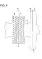
FIG. 4 is a development view showing an essential portion of the terminal fitting, and -
FIG. 5 is a side view of a conventional terminal fitting showing an essential portion in section. - Hereinafter, one particular embodiment of the present invention is described with reference to
FIGS. 1 to 4 . A terminal fitting 10 according to this embodiment is integrally or unitarily formed by performing a bending, folding and/or embossing process and the like on an electrically conductive (particularly metal) plate made e.g. of copper or copper alloy and to be connected to (particularly an end portion of) awire 60. - The
wire 60 is composed of or comprises an electricallyconductive core 61, for example, made of aluminum or aluminum alloy and aninsulation coating 62 made e.g. of resin and at least partly covering thecore 61. At the end portion of thewire 60, thecore 61 is exposed e.g. by stripping off theinsulation coating 62. - A
main portion 11 in the form of a (particularly substantially rectangular or polygonal) tube is formed at a front part of the terminal fitting 10. An unillustrated resilient contact piece particularly is resiliently deformably formed in themain portion 11. When a male tab of an unillustrated mating terminal fitting is at least partly inserted into themain portion 11 as connectors are connected, it resiliently comes into contact with the resilient contact piece, whereby the two terminal fittings are electrically connected. It should be understood, however, that the invention is not limited to a female terminal fitting and can be equally applied to a male terminal fitting. - At least one wire barrel 12 (as a particular wire connection portion) and/or at least one
insulation barrel 13 are formed one after the other at or near a rear part of the terminal fitting 10. Thewire barrel 12 is to be crimped or deformed or bent and connected to thecore 61 at the end portion of thewire 60 and includes, as shown inFIG. 4 , a substantially strip-shapedbase plate portion 14 and one or more, particularly a pair ofwire barrel pieces 15 laterally projecting from (particularly the substantially opposite lateral edges of) thebase plate portion 14. Thebase plate portion 14 is for at least partly supporting thewire 60 and/or particularly extends over the substantially entire length of the terminal fitting 10. The (particularly both) wire barrel piece(s) 15 at least partly is/are wound or bent or folded around thecore 61 at the end portion of the wire 60 (particularly substantially from opposite sides) and held in this state. A plurality ofserrations 16 particularly are formed substantially in the entire inner surface of thewire barrel 12. Thewire 60 is firmly held by the terminal fitting 10 by thecore 61 being locked in therespective serrations 16. - The
insulation barrel 13 includes one or more, particularly a pair ofinsulation barrel pieces 17 laterally projecting from (particularly substantially the opposite lateral edges of) thebase plate portion 14. The (particularly both) insulation barrel piece(s) 17 is/are to be wound or bent or folded at least partly around the insulation coating 62 at or near the end portion of the wire 60 (particularly from substantially opposite sides) and held in this state. Theinsulation barrel pieces 17 particularly have a larger projecting distance than thewire barrel pieces 15 and/or a smaller dimension in forward and backward directions than thewire barrel pieces 15. The bothinsulation barrel pieces 17 particularly have a substantially semicircular cross section and/or the outer peripheral surfaces of end edge portions thereof particularly are substantially held in contact (seeFIG. 2 ) in a state where theinsulation barrel pieces 17 are wound around thewire 60. - As shown in
FIG. 1 , at least one close-contact portion 18 to be held in close contact with the outer surface of theinsulation coating 62 and/or at least onerecessed groove 19 spaced apart from theinsulation coating 62 without being held in contact with the outer surface of theinsulation coating 62 are formed on the inner surface of theinsulation barrel 13. Therecessed groove 19 is formed at or near a front end portion of theinsulation barrel 13 and the close-contact portion 18 is formed at or near a rear portion of theinsulation barrel 13 at least partly excluding therecessed groove 19. The close-contact portion 18 is to be held in close contact with the outer surface of theinsulation coating 62 particularly substantially over the entire circumference. - The
recessed groove 19 particularly has a strip-shaped plan view extending straight over the entire widths of thebase plate portion 14 and/or the both insulation barrel pieces 17 (seeFIG. 4 ). Further, therecessed groove 19 particularly has at least one opening 21 which is open at the front ends of the insulation barrel piece(s) 17. With theinsulation barrel 13 wound or bent or folded around thewire 60, therecessed groove 19 is arranged to surround the insulation coating 62 (particularly substantially over the entire circumference) without being held in contact with theinsulation coating 62. - Specifically, the recessed
groove 19 is formed within the plate thickness range of theinsulation barrel 13 particularly by press-working the inner surface of theinsulation barrel 13. More specifically, the recessedgroove 19 has a dimension in forward and backward directions (groove width) smaller than about half the dimension of theinsulation barrel 13 in forward and backward directions and/or a depth smaller than about half the thickness of theinsulation barrel 13. - Next, functions and effects of the terminal fitting 10 according to this embodiment are described.
- By crimping, folding or bending and connecting the
wire barrel 12 to thecore 61 and/or crimping, folding or bending and connecting theinsulation barrel 13 to theinsulation coating 62, the terminal fitting 10 is connected to the end portion of thewire 60. In this case, the front end of theinsulation coating 62 is arranged behind the front end of theinsulation barrel 13 and in the recessedgroove 19. Thus, as shown inFIG. 3 , the front end portion of theinsulation coating 62 is hidden in theinsulation barrel 13 and is not radially widened. Further, with the terminal fitting 10 connected to thewire 60, arecess 50 is defined by the rear end of thewire barrel 12, the outer surface of thecore 61 and the front end of theinsulation barrel 13. - Subsequently, a fluid- or liquid- or waterproof material in a liquid state is adhered to the outer surface of the
core 61. In this case, thewaterproof material 40 is caused to at least partly flow into therecess 50, whereby thewaterproof material 40 reliably adheres to the outer surface of the core 61 located in therecess 50 and at least partly flows into the recessedgroove 19 through the opening(s) 21. Thus, the fluid- or liquid- or waterproof material adheres to the core 61 located in theinsulation barrel 13 particularly substantially over its entire circumference (seeFIG. 2 ). Note that an anticorrosion material containing insulating resin such as silicon resin can be used as thewaterproof material 40. - Thereafter, when the
waterproof material 40 is cured, a coating area of thewaterproof material 40 is formed on the outer surface of the core 61 to ensure waterproofness in a connected part and prevent the occurrence of electrical corrosion. - As described above, according to this embodiment, the recessed
groove 19 spaced apart from theinsulation coating 62 is formed in the inner surface of theinsulation barrel 13 and the fluid- or liquid- orwaterproof material 40 flows into the recessedgroove 19 through theopening 21. Thus, thewaterproof material 40 spreads also to the inside of theinsulation barrel 13. As a result, thewaterproof material 40 reliably adheres to the outer surface of thecore 61. - Further, since the recessed
groove 19 particularly is formed within the plate thickness range of theinsulation barrel 13, theinsulation barrel 13 does not have to be radially enlarged. As a result, interference of theinsulation barrel 13 with the inner surface of a cavity can be avoided, for example, when the terminal fitting 10 is inserted into the cavity of a connector housing. - Furthermore, since the front end of the
insulation coating 62 particularly is located in the recessedgroove 19, thewaterproof material 40 adheres also to the part of the core 61 located inside theinsulation barrel 13. In this case, the front end portion of theinsulation coating 62 is not widened and it is not necessary to adjust the projecting margin of theinsulation coating 62. - Accordingly, to enable a waterproof material to reliably adhere to the outer surface of a core, a terminal fitting 10 includes a wire barrel 12 (as a particular wire connection portion) to be crimped, folded or bent and connected to a core 61 at an end portion of a
wire 60 and at least oneinsulation barrel 13 located behind thewire barrel 12 and to be crimped and connected to aninsulation coating 62 at the end portion of thewire 60. The inner surface of theinsulation barrel 13 is formed with a close-contact portion 18 to be held in close contact with theinsulation coating 62 and a recessedgroove 19 spaced apart from theinsulation coating 62 and extending over the entire circumference. The recessedgroove 19 has anopening 21 which is open at the front end of theinsulation barrel 13 and awaterproof material 40 flows into the recessedgroove 19 through theopening 21. Thewaterproof material 40 adheres to the outer surface of thecore 61. - The present invention is not limited to the above described and illustrated embodiment. For example, the following embodiments are also included in the technical scope of the present invention.
- (1) The core of the wire and the terminal fitting may be made of the same type of metal (e.g. both are made of copper or copper alloy).
- (2) The present invention is also applicable to male terminals in which a male tab projects forward.
- (3) The invention is also applicable to a terminal fitting being electrically connected to the core of the wire by insulation displacement or any other means such as soldering, welding, gluing or the like.
-
- 10
- ... terminal fitting
- 12
- ... wire barrel (wire connection portion)
- 13
- ... insulation barrel
- 18
- ... close-contact portion
- 19
- ... recessed groove
- 21
- ... opening
- 40
- ... waterproof material
- 60
- ... wire
- 61
- ... core
- 62
- ... insulation coating
Claims (10)
- A terminal fitting (10) formed by bending an electrically conductive plate material, comprising:a wire connection portion (12) to be electrically connected to a core (61) of a wire (60); andat least one insulation barrel (13) located behind the wire connection portion (12) and to be crimped and connected to an insulation coating (62) of the wire (60), wherein:the inner surface of the insulation barrel (13) is formed with a close-contact portion (18) to be held in close contact with the insulation coating (62) and at least one recessed groove (19) spaced apart from the insulation coating (62);the recessed groove (19) has at least one opening (21) which is open at the front end of the insulation barrel (13) so that a fluidproof material (40) can flow into the recessed groove (19) through the opening (21) and adhere to the outer surface of the core (61) and/or insulation coating (62).
- A terminal fitting according to claim 1, wherein the recessed groove (19) extends over the entire circumference of the insulation coating (62).
- A terminal fitting according to any one of the preceding claims, wherein the recessed groove (19) is formed within the plate thickness range of the insulation barrel (13).
- A terminal fitting according to any one of the preceding claims, wherein the front end of the insulation coating (62) is to be located in the recessed groove (19).
- A terminal fitting according to any one of the preceding claims, wherein the recessed groove (19) has a strip-shaped plan view substantially extending straight.
- A terminal fitting according to any one of the preceding claims, wherein the insulation barrel (13) has a larger projecting distance than the wire connection portion (12) and/or a smaller dimension in forward and backward directions than the connection portion (12).
- A terminal fitting according to any one of the preceding claims, wherein the wire connection portion (12) comprises at least one wire barrel (12) to be crimped into connection with the core (61), wherein at least one serration (16) is formed on an inner surface of the wire barrel (12).
- A method of connecting a terminal fitting (10) formed by bending an electrically conductive plate material to a wire, comprising:electrically connecting a wire connection portion (12) of the terminal fitting (10) to a core (61) of a wire (60); andcrimping and connecting at least one insulation barrel (13) located behind the wire connection portion (12) to an insulation coating (62) of the wire (60), whereby a close-contact portion (18) of the inner surface of the insulation barrel (13) is held in close contact with the insulation coating (62) and at least one recessed groove (19) is held spaced apart from the insulation coating (62);flowing a fluidproof material (40) into the recessed groove (19) through at least one opening (21) of the recessed groove (19) such that the fluidproof material (40) adheres to the outer surface of the core (61) and/or insulation coating (62).
- A method according to claim 8, wherein the recessed groove (19) extends over the entire circumference of the insulation coating (62) and the fluidproof material (40) adheres to the outer surface of the core (61) and/or insulation coating (62) substantially over the entire circumference of the wire (60).
- A method according to claim 8 or 9, wherein the front end of the insulation coating (62) is located in the recessed groove (19).
Applications Claiming Priority (1)
| Application Number | Priority Date | Filing Date | Title |
|---|---|---|---|
| JP2011024092A JP5601233B2 (en) | 2011-02-07 | 2011-02-07 | Terminal fitting |
Publications (1)
| Publication Number | Publication Date |
|---|---|
| EP2485330A1 true EP2485330A1 (en) | 2012-08-08 |
Family
ID=45654746
Family Applications (1)
| Application Number | Title | Priority Date | Filing Date |
|---|---|---|---|
| EP12000217A Withdrawn EP2485330A1 (en) | 2011-02-07 | 2012-01-16 | Terminal fitting and method of connecting it |
Country Status (4)
| Country | Link |
|---|---|
| US (1) | US8616928B2 (en) |
| EP (1) | EP2485330A1 (en) |
| JP (1) | JP5601233B2 (en) |
| CN (1) | CN102629719B (en) |
Cited By (1)
| Publication number | Priority date | Publication date | Assignee | Title |
|---|---|---|---|---|
| WO2014154706A1 (en) * | 2013-03-25 | 2014-10-02 | Tyco Electronics Amp Gmbh | Crimp connection |
Families Citing this family (12)
| Publication number | Priority date | Publication date | Assignee | Title |
|---|---|---|---|---|
| JP5063750B2 (en) * | 2010-07-23 | 2012-10-31 | 株式会社オートネットワーク技術研究所 | Terminal structure of wire harness |
| JP6192947B2 (en) * | 2013-02-20 | 2017-09-06 | 矢崎総業株式会社 | Electric wire with terminal bracket |
| JP6271228B2 (en) * | 2013-11-25 | 2018-01-31 | 矢崎総業株式会社 | Crimping method of electric wire to terminal |
| JP2016164836A (en) * | 2015-03-06 | 2016-09-08 | 株式会社オートネットワーク技術研究所 | Electric wire with terminal and terminal |
| JP6402930B2 (en) * | 2015-03-06 | 2018-10-10 | 株式会社オートネットワーク技術研究所 | Terminal and electric wire with terminal |
| JP6928822B2 (en) * | 2016-05-25 | 2021-09-01 | 古河電気工業株式会社 | Wire with terminal |
| JP2018045762A (en) * | 2016-09-12 | 2018-03-22 | 矢崎総業株式会社 | Crimp terminal |
| JP6928435B2 (en) * | 2016-10-11 | 2021-09-01 | 古河電気工業株式会社 | Manufacturing method of electric wire with terminal |
| JP6709808B2 (en) * | 2018-01-24 | 2020-06-17 | 矢崎総業株式会社 | Wire with terminal |
| JP6976990B2 (en) * | 2019-05-21 | 2021-12-08 | 矢崎総業株式会社 | Wire with terminal |
| JP7116112B2 (en) * | 2020-03-18 | 2022-08-09 | 矢崎総業株式会社 | Wire with terminal |
| JP2021150235A (en) * | 2020-03-23 | 2021-09-27 | 矢崎総業株式会社 | Terminal-having electric wire and manufacturing method for terminal-having electric wire |
Citations (5)
| Publication number | Priority date | Publication date | Assignee | Title |
|---|---|---|---|---|
| EP0544521A2 (en) * | 1991-11-26 | 1993-06-02 | Sumitomo Wiring Systems, Ltd. | Terminal for fixing wires |
| JP2003217697A (en) * | 2002-01-18 | 2003-07-31 | Sumitomo Wiring Syst Ltd | Shield connector |
| EP1383202A1 (en) * | 2002-07-17 | 2004-01-21 | Souriau | Connection device between cable and contact element |
| FR2920599A1 (en) * | 2007-09-05 | 2009-03-06 | Mecatraction Sa | Lug for electric connection, has socket presenting hollow partially filled with contact grease that is placed between base of hollow and transversal membrane, and stopper maintaining grease and hollow |
| JP2010049941A (en) | 2008-08-21 | 2010-03-04 | Sumitomo Wiring Syst Ltd | Connection structure of electric wire and terminal metal fitting |
Family Cites Families (3)
| Publication number | Priority date | Publication date | Assignee | Title |
|---|---|---|---|---|
| JP5264081B2 (en) * | 2007-01-29 | 2013-08-14 | 矢崎総業株式会社 | Line water-stop method and line water-stop device |
| CN101946368A (en) * | 2008-02-15 | 2011-01-12 | 株式会社自动网络技术研究所 | Terminal connector and bunch |
| JP2010040456A (en) * | 2008-08-07 | 2010-02-18 | Sumitomo Wiring Syst Ltd | Terminal fitting and wire harness |
-
2011
- 2011-02-07 JP JP2011024092A patent/JP5601233B2/en not_active Expired - Fee Related
-
2012
- 2012-01-16 EP EP12000217A patent/EP2485330A1/en not_active Withdrawn
- 2012-01-30 US US13/361,161 patent/US8616928B2/en not_active Expired - Fee Related
- 2012-01-31 CN CN201210021849.8A patent/CN102629719B/en not_active Expired - Fee Related
Patent Citations (5)
| Publication number | Priority date | Publication date | Assignee | Title |
|---|---|---|---|---|
| EP0544521A2 (en) * | 1991-11-26 | 1993-06-02 | Sumitomo Wiring Systems, Ltd. | Terminal for fixing wires |
| JP2003217697A (en) * | 2002-01-18 | 2003-07-31 | Sumitomo Wiring Syst Ltd | Shield connector |
| EP1383202A1 (en) * | 2002-07-17 | 2004-01-21 | Souriau | Connection device between cable and contact element |
| FR2920599A1 (en) * | 2007-09-05 | 2009-03-06 | Mecatraction Sa | Lug for electric connection, has socket presenting hollow partially filled with contact grease that is placed between base of hollow and transversal membrane, and stopper maintaining grease and hollow |
| JP2010049941A (en) | 2008-08-21 | 2010-03-04 | Sumitomo Wiring Syst Ltd | Connection structure of electric wire and terminal metal fitting |
Cited By (1)
| Publication number | Priority date | Publication date | Assignee | Title |
|---|---|---|---|---|
| WO2014154706A1 (en) * | 2013-03-25 | 2014-10-02 | Tyco Electronics Amp Gmbh | Crimp connection |
Also Published As
| Publication number | Publication date |
|---|---|
| JP5601233B2 (en) | 2014-10-08 |
| CN102629719A (en) | 2012-08-08 |
| US20120202394A1 (en) | 2012-08-09 |
| JP2012164523A (en) | 2012-08-30 |
| CN102629719B (en) | 2015-07-22 |
| US8616928B2 (en) | 2013-12-31 |
Similar Documents
| Publication | Publication Date | Title |
|---|---|---|
| US8616928B2 (en) | Terminal fitting and a method for forming a fluid-proof terminated wire assembly | |
| JP5098890B2 (en) | Connection structure between wires and terminal fittings | |
| CN105580213B (en) | Terminal fittings | |
| CN103947045B (en) | Electric wire and the terminal of terminal are installed | |
| JP5241529B2 (en) | Chain terminal, terminal fitting, and manufacturing method of terminal fitting | |
| EP2602881B1 (en) | Anti-corrosion structure for wire connection section | |
| CN104067446B (en) | Clamped nipple | |
| EP2375512B1 (en) | Terminal fitting and production method therefor | |
| JP5195244B2 (en) | Terminal fittings and electric wires with terminal fittings | |
| CN104247153A (en) | Connection terminal | |
| EP2159880A1 (en) | A terminal fitting and a wire connected with a terminal fitting | |
| CN110323581A (en) | Electric wire with terminal | |
| EP1821375A2 (en) | A terminal fitting, a method of crimping it and a positioning jig | |
| JP2011192586A (en) | Cable having terminal fitting, and manufacturing method for same | |
| US10644415B2 (en) | Terminal-equipped wire and method for crimping terminal onto wire | |
| JP2010015708A (en) | Shield connector | |
| JP2010055903A (en) | Terminal fitting and electric wire equipped therewith | |
| JP5787918B2 (en) | Crimp terminal and wire harness using crimp terminal | |
| JP2010061906A (en) | Electric wire with terminal fitting | |
| US7985104B2 (en) | Shield sleeve for a plug connector | |
| EP2164132A1 (en) | A terminal fitting, a connector, and assembling method therefor | |
| JP2010067370A (en) | Connector | |
| JP7233230B2 (en) | TERMINAL, ELECTRIC WIRE WITH TERMINAL AND MANUFACTURING METHOD THEREOF | |
| JP2010073345A (en) | Connection structure of terminal metal fitting, electric wire with terminal metal fitting, and manufacturing method of electric wire with terminal metal fitting | |
| JP5830479B2 (en) | Wire harness |
Legal Events
| Date | Code | Title | Description |
|---|---|---|---|
| PUAI | Public reference made under article 153(3) epc to a published international application that has entered the european phase |
Free format text: ORIGINAL CODE: 0009012 |
|
| AK | Designated contracting states |
Kind code of ref document: A1 Designated state(s): AL AT BE BG CH CY CZ DE DK EE ES FI FR GB GR HR HU IE IS IT LI LT LU LV MC MK MT NL NO PL PT RO RS SE SI SK SM TR |
|
| AX | Request for extension of the european patent |
Extension state: BA ME |
|
| 17P | Request for examination filed |
Effective date: 20120816 |
|
| GRAP | Despatch of communication of intention to grant a patent |
Free format text: ORIGINAL CODE: EPIDOSNIGR1 |
|
| RIC1 | Information provided on ipc code assigned before grant |
Ipc: H01R 4/70 20060101AFI20150803BHEP Ipc: H01R 4/18 20060101ALI20150803BHEP |
|
| INTG | Intention to grant announced |
Effective date: 20150817 |
|
| RIN1 | Information on inventor provided before grant (corrected) |
Inventor name: UCHIYAMA, YOSHIHIRO |
|
| STAA | Information on the status of an ep patent application or granted ep patent |
Free format text: STATUS: THE APPLICATION IS DEEMED TO BE WITHDRAWN |
|
| 18D | Application deemed to be withdrawn |
Effective date: 20160105 |