EP2485311A1 - Fuel cell device - Google Patents
Fuel cell device Download PDFInfo
- Publication number
- EP2485311A1 EP2485311A1 EP10820302A EP10820302A EP2485311A1 EP 2485311 A1 EP2485311 A1 EP 2485311A1 EP 10820302 A EP10820302 A EP 10820302A EP 10820302 A EP10820302 A EP 10820302A EP 2485311 A1 EP2485311 A1 EP 2485311A1
- Authority
- EP
- European Patent Office
- Prior art keywords
- hydrogen
- fuel cell
- producing member
- cell apparatus
- hydrogen producing
- Prior art date
- Legal status (The legal status is an assumption and is not a legal conclusion. Google has not performed a legal analysis and makes no representation as to the accuracy of the status listed.)
- Withdrawn
Links
Images

Classifications
-
- H—ELECTRICITY
- H01—ELECTRIC ELEMENTS
- H01M—PROCESSES OR MEANS, e.g. BATTERIES, FOR THE DIRECT CONVERSION OF CHEMICAL ENERGY INTO ELECTRICAL ENERGY
- H01M8/00—Fuel cells; Manufacture thereof
- H01M8/06—Combination of fuel cells with means for production of reactants or for treatment of residues
- H01M8/0606—Combination of fuel cells with means for production of reactants or for treatment of residues with means for production of gaseous reactants
- H01M8/065—Combination of fuel cells with means for production of reactants or for treatment of residues with means for production of gaseous reactants by dissolution of metals or alloys; by dehydriding metallic substances
-
- C—CHEMISTRY; METALLURGY
- C01—INORGANIC CHEMISTRY
- C01B—NON-METALLIC ELEMENTS; COMPOUNDS THEREOF; METALLOIDS OR COMPOUNDS THEREOF NOT COVERED BY SUBCLASS C01C
- C01B3/00—Hydrogen; Gaseous mixtures containing hydrogen; Separation of hydrogen from mixtures containing it; Purification of hydrogen; Reversible storage of hydrogen
- C01B3/02—Production of hydrogen; Production of gaseous mixtures containing hydrogen
- C01B3/32—Production of hydrogen; Production of gaseous mixtures containing hydrogen by reaction of gaseous or liquid organic compounds with gasifying agents, e.g. water, carbon dioxide or air
- C01B3/34—Production of hydrogen; Production of gaseous mixtures containing hydrogen by reaction of gaseous or liquid organic compounds with gasifying agents, e.g. water, carbon dioxide or air by reaction of hydrocarbons with gasifying agents
-
- H—ELECTRICITY
- H01—ELECTRIC ELEMENTS
- H01M—PROCESSES OR MEANS, e.g. BATTERIES, FOR THE DIRECT CONVERSION OF CHEMICAL ENERGY INTO ELECTRICAL ENERGY
- H01M8/00—Fuel cells; Manufacture thereof
- H01M8/04—Auxiliary arrangements, e.g. for control of pressure or for circulation of fluids
- H01M8/04082—Arrangements for control of reactant parameters, e.g. pressure or concentration
- H01M8/04201—Reactant storage and supply, e.g. means for feeding, pipes
- H01M8/04216—Reactant storage and supply, e.g. means for feeding, pipes characterised by the choice for a specific material, e.g. carbon, hydride, absorbent
-
- H—ELECTRICITY
- H01—ELECTRIC ELEMENTS
- H01M—PROCESSES OR MEANS, e.g. BATTERIES, FOR THE DIRECT CONVERSION OF CHEMICAL ENERGY INTO ELECTRICAL ENERGY
- H01M8/00—Fuel cells; Manufacture thereof
- H01M8/04—Auxiliary arrangements, e.g. for control of pressure or for circulation of fluids
- H01M8/04298—Processes for controlling fuel cells or fuel cell systems
- H01M8/04313—Processes for controlling fuel cells or fuel cell systems characterised by the detection or assessment of variables; characterised by the detection or assessment of failure or abnormal function
- H01M8/04537—Electric variables
- H01M8/04544—Voltage
-
- H—ELECTRICITY
- H01—ELECTRIC ELEMENTS
- H01M—PROCESSES OR MEANS, e.g. BATTERIES, FOR THE DIRECT CONVERSION OF CHEMICAL ENERGY INTO ELECTRICAL ENERGY
- H01M8/00—Fuel cells; Manufacture thereof
- H01M8/04—Auxiliary arrangements, e.g. for control of pressure or for circulation of fluids
- H01M8/04298—Processes for controlling fuel cells or fuel cell systems
- H01M8/04694—Processes for controlling fuel cells or fuel cell systems characterised by variables to be controlled
- H01M8/04746—Pressure; Flow
- H01M8/04753—Pressure; Flow of fuel cell reactants
-
- H—ELECTRICITY
- H01—ELECTRIC ELEMENTS
- H01M—PROCESSES OR MEANS, e.g. BATTERIES, FOR THE DIRECT CONVERSION OF CHEMICAL ENERGY INTO ELECTRICAL ENERGY
- H01M8/00—Fuel cells; Manufacture thereof
- H01M8/04—Auxiliary arrangements, e.g. for control of pressure or for circulation of fluids
- H01M8/04298—Processes for controlling fuel cells or fuel cell systems
- H01M8/04694—Processes for controlling fuel cells or fuel cell systems characterised by variables to be controlled
- H01M8/04746—Pressure; Flow
- H01M8/04776—Pressure; Flow at auxiliary devices, e.g. reformer, compressor, burner
-
- H—ELECTRICITY
- H01—ELECTRIC ELEMENTS
- H01M—PROCESSES OR MEANS, e.g. BATTERIES, FOR THE DIRECT CONVERSION OF CHEMICAL ENERGY INTO ELECTRICAL ENERGY
- H01M8/00—Fuel cells; Manufacture thereof
- H01M8/18—Regenerative fuel cells, e.g. redox flow batteries or secondary fuel cells
- H01M8/184—Regeneration by electrochemical means
- H01M8/186—Regeneration by electrochemical means by electrolytic decomposition of the electrolytic solution or the formed water product
-
- C—CHEMISTRY; METALLURGY
- C01—INORGANIC CHEMISTRY
- C01B—NON-METALLIC ELEMENTS; COMPOUNDS THEREOF; METALLOIDS OR COMPOUNDS THEREOF NOT COVERED BY SUBCLASS C01C
- C01B2203/00—Integrated processes for the production of hydrogen or synthesis gas
- C01B2203/02—Processes for making hydrogen or synthesis gas
- C01B2203/0205—Processes for making hydrogen or synthesis gas containing a reforming step
- C01B2203/0211—Processes for making hydrogen or synthesis gas containing a reforming step containing a non-catalytic reforming step
- C01B2203/0216—Processes for making hydrogen or synthesis gas containing a reforming step containing a non-catalytic reforming step containing a non-catalytic steam reforming step
-
- C—CHEMISTRY; METALLURGY
- C01—INORGANIC CHEMISTRY
- C01B—NON-METALLIC ELEMENTS; COMPOUNDS THEREOF; METALLOIDS OR COMPOUNDS THEREOF NOT COVERED BY SUBCLASS C01C
- C01B2203/00—Integrated processes for the production of hydrogen or synthesis gas
- C01B2203/02—Processes for making hydrogen or synthesis gas
- C01B2203/0205—Processes for making hydrogen or synthesis gas containing a reforming step
- C01B2203/0227—Processes for making hydrogen or synthesis gas containing a reforming step containing a catalytic reforming step
- C01B2203/0233—Processes for making hydrogen or synthesis gas containing a reforming step containing a catalytic reforming step the reforming step being a steam reforming step
-
- C—CHEMISTRY; METALLURGY
- C01—INORGANIC CHEMISTRY
- C01B—NON-METALLIC ELEMENTS; COMPOUNDS THEREOF; METALLOIDS OR COMPOUNDS THEREOF NOT COVERED BY SUBCLASS C01C
- C01B2203/00—Integrated processes for the production of hydrogen or synthesis gas
- C01B2203/02—Processes for making hydrogen or synthesis gas
- C01B2203/0205—Processes for making hydrogen or synthesis gas containing a reforming step
- C01B2203/0227—Processes for making hydrogen or synthesis gas containing a reforming step containing a catalytic reforming step
- C01B2203/0244—Processes for making hydrogen or synthesis gas containing a reforming step containing a catalytic reforming step the reforming step being an autothermal reforming step, e.g. secondary reforming processes
-
- C—CHEMISTRY; METALLURGY
- C01—INORGANIC CHEMISTRY
- C01B—NON-METALLIC ELEMENTS; COMPOUNDS THEREOF; METALLOIDS OR COMPOUNDS THEREOF NOT COVERED BY SUBCLASS C01C
- C01B2203/00—Integrated processes for the production of hydrogen or synthesis gas
- C01B2203/02—Processes for making hydrogen or synthesis gas
- C01B2203/0283—Processes for making hydrogen or synthesis gas containing a CO-shift step, i.e. a water gas shift step
-
- C—CHEMISTRY; METALLURGY
- C01—INORGANIC CHEMISTRY
- C01B—NON-METALLIC ELEMENTS; COMPOUNDS THEREOF; METALLOIDS OR COMPOUNDS THEREOF NOT COVERED BY SUBCLASS C01C
- C01B2203/00—Integrated processes for the production of hydrogen or synthesis gas
- C01B2203/04—Integrated processes for the production of hydrogen or synthesis gas containing a purification step for the hydrogen or the synthesis gas
- C01B2203/042—Purification by adsorption on solids
- C01B2203/043—Regenerative adsorption process in two or more beds, one for adsorption, the other for regeneration
-
- C—CHEMISTRY; METALLURGY
- C01—INORGANIC CHEMISTRY
- C01B—NON-METALLIC ELEMENTS; COMPOUNDS THEREOF; METALLOIDS OR COMPOUNDS THEREOF NOT COVERED BY SUBCLASS C01C
- C01B2203/00—Integrated processes for the production of hydrogen or synthesis gas
- C01B2203/04—Integrated processes for the production of hydrogen or synthesis gas containing a purification step for the hydrogen or the synthesis gas
- C01B2203/0465—Composition of the impurity
- C01B2203/0475—Composition of the impurity the impurity being carbon dioxide
-
- C—CHEMISTRY; METALLURGY
- C01—INORGANIC CHEMISTRY
- C01B—NON-METALLIC ELEMENTS; COMPOUNDS THEREOF; METALLOIDS OR COMPOUNDS THEREOF NOT COVERED BY SUBCLASS C01C
- C01B2203/00—Integrated processes for the production of hydrogen or synthesis gas
- C01B2203/06—Integration with other chemical processes
- C01B2203/062—Hydrocarbon production, e.g. Fischer-Tropsch process
-
- C—CHEMISTRY; METALLURGY
- C01—INORGANIC CHEMISTRY
- C01B—NON-METALLIC ELEMENTS; COMPOUNDS THEREOF; METALLOIDS OR COMPOUNDS THEREOF NOT COVERED BY SUBCLASS C01C
- C01B2203/00—Integrated processes for the production of hydrogen or synthesis gas
- C01B2203/14—Details of the flowsheet
- C01B2203/148—Details of the flowsheet involving a recycle stream to the feed of the process for making hydrogen or synthesis gas
-
- Y—GENERAL TAGGING OF NEW TECHNOLOGICAL DEVELOPMENTS; GENERAL TAGGING OF CROSS-SECTIONAL TECHNOLOGIES SPANNING OVER SEVERAL SECTIONS OF THE IPC; TECHNICAL SUBJECTS COVERED BY FORMER USPC CROSS-REFERENCE ART COLLECTIONS [XRACs] AND DIGESTS
- Y02—TECHNOLOGIES OR APPLICATIONS FOR MITIGATION OR ADAPTATION AGAINST CLIMATE CHANGE
- Y02E—REDUCTION OF GREENHOUSE GAS [GHG] EMISSIONS, RELATED TO ENERGY GENERATION, TRANSMISSION OR DISTRIBUTION
- Y02E60/00—Enabling technologies; Technologies with a potential or indirect contribution to GHG emissions mitigation
- Y02E60/30—Hydrogen technology
- Y02E60/50—Fuel cells
Definitions
- the present invention relates to a fuel cell apparatus, and more particularly, to a fuel cell apparatus which includes a hydrogen producing member.
- fuel cells generate electric power from hydrogen and oxygen in air, and efficiency in generating electric power theoretically is high. Accordingly, the fuel cells can save energy.
- fuel cells discharge only water as excretions at the time of generation of electricity, and do not discharge carbon dioxides and nitrogen oxides, they are evaluated as a eco-friendly power generating method. Consequently, the fuel cells are expected as a powerful card for solving energy and environment concern on a global basis.
- Such a fuel cell has typically the following structure.
- a solid polymer electrolyte membrane which employs a solid polymer ion exchange membrane, a solid oxide electrolyte membrane which employs yttria-stabilized zirconia (YSZ), or the like is sandwiched between a fuel electrode and an air electrode (oxygen electrode), and the resulting laminated structure is further sandwiched between a pair of separators so as to form one cell.
- a hydrogen flow passage and an air flow passage are disposed.
- the hydrogen flow passage is configured to supply hydrogen as one example of fuel gas to the fuel electrode
- the air flow passage is configured to supply air to the air electrode.
- Patent Document 1 teaches a technique to dispose in a fuel cell body a hydrogen producing member which produces hydrogen by making predetermined metal fine particles react with water, and to supply the hydrogen produced by this hydrogen producing member to a fuel electrode.
- water produced by electricity generation in the fuel cell body is supplied as water required for hydrogen generation. Accordingly, it is not required to carry water required for hydrogen generation.
- the hydrogen produced by the hydrogen producing member is supplied to the fuel electrode, and then, in the fuel electrode, the supplied hydrogen is oxidized so as to generate electricity, whereby water is reproduced again, and the above cyclical processes are utilized. As a result, it is not required to supply hydrogen from the outside, and it becomes possible to continue the electricity generating action.
- Patent Document No. 1 Japanese Unexamined Patent Publication No. 2009-99491 official report
- the present invention has been achieved in view of the above-mentioned problems, and an object of the present invention is to provide a fuel cell apparatus which maintains stable performances, can continue the electricity generation for a long term, and has a long service life.
- the structure is equipped with a fuel cell body which includes an electricity generating section to generate electricity through a reaction between hydrogen and oxygen, and a hydrogen producing member which produces hydrogen through a reaction with water produced in the course of the electricity generation, and supplies the produced hydrogen to the electricity generating section; and a reduction controller to control so as to reduce the hydrogen producing member oxidized through the reaction with the produced water.
- a fuel cell body which includes an electricity generating section to generate electricity through a reaction between hydrogen and oxygen, and a hydrogen producing member which produces hydrogen through a reaction with water produced in the course of the electricity generation, and supplies the produced hydrogen to the electricity generating section; and a reduction controller to control so as to reduce the hydrogen producing member oxidized through the reaction with the produced water.
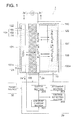
- Fig. 1 is a schematic diagram showing the outline structure of a fuel cell apparatus 1 in the embodiment.
- the fuel cell apparatus 1 includes a fuel cell body 10, a reduction controller 20, and the like.
- the fuel cell body 10 is shown by a cross-sectional schematic diagram
- the reduction controller 20 is shown by a block diagram.
- the fuel cell body 10 includes an electrolyte membrane 101, a fuel electrode 102, an air electrode (oxygen electrode) 103, a hydrogen producing member 105, a heater 107, a temperature sensor 108, a cover member 110, and the like.
- the fuel cell body 10 has a MEA (Membrane Electrode Assembly; membrane electrode joint unit) structure in which the electrolyte membrane 101 is jointed between the fuel electrode 102 and the air electrode 103.
- An electricity generating section 104 is constituted by these three members of the electrolyte membrane 101, the fuel electrode 102, and the air electrode 103.
- a hydrogen producing member 105 configured to supply hydrogen being fuel gas to the fuel electrode 102
- an air flow passage 121 through which air being oxidant gas is supplied to the air electrode 103.
- fuel hydrogen, methanol, and the like
- oxidant gas gas containing oxygen may be used.
- hydrogen and air are used as fuel and oxidant gas, respectively.
- Examples of the material of the electrolyte membrane 101 include a solid oxide electrolyte employing stabilized yttria zirconium (YSZ), Nafion (trademark of E. I. du Pont de Nemours & Co.), and cationic conductive or anionic conductive solid polymer electrolyte.
- the examples further include materials satisfying the characteristics as the electrolyte of a fuel cell, such as materials to allow hydrogen ion to pass through, materials to allow oxygen ion to pass through, and materials to allow hydroxide ion to pass through.
- an electrochemical vapor deposition method (CVD-EVD method; Chemical Vapor Deposition-Electrochemical Vapor Deposition) may be employed, and in the case of solid polymer electrolytes, a coating method may be employed.
- Each of the fuel electrode 102 and the air electrode 103 includes a catalyst layer (in which, for example, platinum blacks or platinum alloys are supported on carbon blacks) disposed in contact with the electrolyte membrane 101, and a diffusion electrode, such as a carbon paper laminated on the catalyst layer.
- a catalyst layer in which, for example, platinum blacks or platinum alloys are supported on carbon blacks
- a diffusion electrode such as a carbon paper laminated on the catalyst layer.
- the hydrogen producing member 105 Fe or Mg alloy which produces hydrogen by a chemical reaction (for example, oxidation), carbon nanotubes which can absorb and desorb hydrogen with the structure of molecules, and the like may be used. In this embodiment, Fe which produces hydrogen by oxidation is used. Further, the hydrogen producing member 105 may not only generate hydrogen, but also may store (adsorb) hydrogen. In this case, after the hydrogen producing member 105 produces hydrogen from itself, the hydrogen producing member 105 conducts an storage (adsorption) action for the hydrogen, whereby the hydrogen producing member 105 can be used repeatedly. As materials capable of storing hydrogen, a hydrogen storing alloy in which Ni, Fe, Pd, V, Mg, or the like is made as a base material, may be used.
- the emission surface 105a of the hydrogen producing member 105 which emits hydrogen, and the supply surface 102a of the fuel electrode 102 to which the hydrogen is supplied, are disposed to face each other, and arranged to be parallel to each other with a predetermined distance between them by a spacer such as beads which is not illustrated in the drawings.
- the emission surface 105a of the hydrogen producing member 105 is configured to emit hydrogen in a planar form.
- the temperature of the entire body of the hydrogen producing member 105 is raised uniformly, whereby hydrogen can be emitted in a planar form from the emission surface 105a.
- the hydrogen producing member 105 can emit hydrogen from almost the entire surface of its emission surface 105a toward almost the entire surface of the supply surface 102a of the fuel electrode 102.
- the hydrogen generation rate of the hydrogen producing member 105 is made approximately constant regardless of locations on the emission surface 105a. Specifically, a thermochemical balance is employed. If the temperature of the hydrogen producing member 105 is raised or lowered, hydrogen corresponding to deviation from an equilibrium condition can be produced. Accordingly, if the temperature of the entire body of the hydrogen producing member 105 is made uniform by use of the heater 107, hydrogen can be produced with a constant rate regardless of locations.
- the hydrogen generating rate of the hydrogen producing member 105 can be made constant.
- a hydrogen concentration at the time of start-up of a cell is made constant regardless of locations, power generated from the electricity generating section 104 becomes constant. That is, the consumption of hydrogen becomes constant regardless of locations.
- the chemical equilibrium deviates due to the consumed hydrogen, hydrogen is newly produced from the hydrogen producing member 105 in accordance with the amount of the deviation. Since the consumption of hydrogen is constant regardless of locations, the hydrogen generating rate from the hydrogen producing member 105 becomes constant regardless of locations.
- hydrogen may be encapsulated or charged in a space portion 125 between the fuel electrode 102 and the hydrogen producing member 105 beforehand.
- the encapsulated hydrogen diffuses naturally, and the concentration in the encapsulated space 125 becomes constant. Accordingly, the concentration of hydrogen can be made constant regardless of locations.
- the emission surface 105a of the hydrogen producing member 105 which emits hydrogen, and the supply surface 102a of the fuel electrode 102 to which the hydrogen is supplied are disposed to face each other, and arranged to be parallel to each other with a predetermined distance.
- the emission surface 105a and the supply surface 102a may be superimposed so as to be in close contact to each other. In this case, since hydrogen with a more uniform concentration can be supplied over the entire surface of the supply surface 102a of the fuel electrode 102, it becomes possible to more effectively suppress lowering of the output due to dispersion in electromotive force, and to enhance more fuel efficiency.
- a cover member 110 is a container to cover the fuel cell body 10, and at its air electrode 103 side, an air supply port 122 to supply air to the air flow passage 121 and an air discharge port 123 to discharge excess air are disposed. By introduction of air from the air supply port 122 to the air flow passage 121, air can be supplied and dispersed to the entire body of the air electrode 103.
- the reduction controller 20 includes a constant current section 201, a voltage detecting section 202, a judgment section 203, a switch section 204, and the like. At the time of suspension of power generation, in the fuel cell body 10, the reduction controller 20 is configured to reduce and reactivate the hydrogen producing member 105 in which oxidation progresses with the generation of electricity.
- the reduction controller 20 makes the oxidized hydrogen producing member 105 (Fe 3 O 4 ) react with hydrogen (H 2 ) produced by electrolysis of water (H 2 O) produced in the fuel cell body 10 during the electricity generation by the fuel cell body 10, whereby the oxidized hydrogen producing member 105 (Fe 3 O 4 ) is reduced.
- the constant current section 201 supplies electric power to be used for electrolysis to the fuel cell body 10.
- the voltage detecting section 202 detects the output voltage of the constant current section 201.
- the judgment section 203 controls the switch section 204 based on the detection result of the voltage detecting section 202, and turns on and off the supply of the electric power from the constant current section 201 to the fuel cell body 10.
- the reduction controller 20 is connected to the power source 30 provided at the outside, whereby electric power is supplied to the reduction controller 20. In this connection, the reduction action will be explained in detail later.
- FIGs. 2A to 2D are schematic diagrams showing the flow of the electricity generating action and the reducing action performed in the fuel cell apparatus 1.
- hydrogen (H 2 ) is encapsulated in the space portion 125 in the fuel cell body 10.
- water (H 2 O) is produced by the fuel electrode 102.
- the produced water (H 2 O) is supplied to the hydrogen producing member 105 (Fe), and then in the hydrogen producing member 105 (Fe), the reaction shown in the following formula (2) is caused by the supplied water (H 2 O), and hydrogen (H 2 ) is produced.
- the produced hydrogen (H 2 ) is supplied to the fuel electrode 102, and then in the fuel electrode 102, the supplied hydrogen (H 2 ) is oxidized so as to generate electricity, whereby water (H 2 O) is produced again, and the above cyclical processes are utilized such that the electricity generating action is continued.
- the fuel electrode 102 and the hydrogen producing member 105 (Fe) are arranged to face each other, and the cyclical utilization of hydrogen (H 2 ) and water (H 2 O) is performed between them. Accordingly, it is not necessary to provide an introducing mechanism for circulating hydrogen (H 2 ) and water (H 2 O) at the outside of the fuel cell body 10. As a result, it becomes possible to miniaturize a fuel cell apparatus and to reduce cost.
- water (H 2 O) is produced by the hydrogen producing member 105.
- the produced water (H 2 O) is supplied to the fuel electrode 102, and then in the fuel electrode 102, the supplied water (H 2 O) is electrolyzed, whereby hydrogen (H 2 ) is produced again, and the above cyclical processes are utilized so that the reducing action is continued.
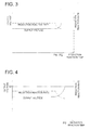
- Fig. 3 is a schematic diagram showing a relationship between a reduction reaction time and each of a reduction reaction speed and the output voltage of the constant current section 201.
- the percentage of iron (Fe) in the hydrogen producing member 105 i.e., the reduction reaction time and the reduction reaction speed have a given relationship
- the reduction reaction speed and the output voltage of the constant current section 201 have a given relationship.
- the judgment section 203 compares the amount of change of the output voltage of the constant current section 201 detected by the voltage detecting section 202 per the reduction reaction time with a threshold value set preliminarily. When the amount of change exceeds the threshold value (in Fig. 3 , at a P2 point), the judgment section 203 suspends the supply of electric power from the constant current section 201 to the fuel cell body 10. With this, the reducing action is suspended.
- the reduction reaction control method 1 when the amount of change of the output voltage of the constant current section 201 per time exceeds the threshold value, that is, when the iron oxide (Fe 3 O 4 ) in the hydrogen producing member 105 changes to iron (Fe) by a predetermined amount, the reduction action is suspended. Accordingly, an excessive reduction reaction can be prevented.
- Fig. 4 is a schematic diagram showing a relationship between a reduction reaction time and each of a reduction reaction rate and the output voltage of the constant current section 201.
- the relationship between a reduction reaction time and each of a reduction reaction rate and the output voltage of the constant current section 201 in Fig. 4 is the same as the case in Fig. 3 , the explanation for that is omitted.
- the judgment section 203 compares the output voltage of the constant current section 201 detected by the voltage detecting section 202 with a threshold value Vr (an upper limit) set preliminarily. When the output voltage exceeds the threshold value Vr (in Fig. 4 , at a P2 point), the judgment section 203 controls the switch section 204 to suspend the supply of electric power from the constant current section 201 to the fuel cell body 10. With this, the reduction action is suspended.
- Vr an upper limit
- the fuel cell apparatus 1 in the embodiment of the present invention includes the fuel cell body 10 having the hydrogen producing member 105 which produces hydrogen (H 2 ) through a reaction with water (H 2 O) produced by the electricity generation and supplies the produced hydrogen (H 2 ) to the fuel electrode 102, and the reduction controller 20 which reduces the hydrogen producing member 105 (Fe 3 O 4 ) oxidized by the reaction with water (H 2 O) in the fuel cell body 10.
- the reduction controller 20 which reduces the hydrogen producing member 105 (Fe 3 O 4 ) oxidized by the reaction with water (H 2 O) in the fuel cell body 10.
- the reduction action when the amount of change of the output voltage of the constant current section 201 per time exceeds the threshold value, or when the output voltage of the constant current section 201 exceeds the threshold value Vr (the upper limit), that is, when the iron oxide (Fe 3 O 4 ) in the hydrogen producing member 105 changes to iron (Fe) by a predetermined amount, the reduction action is suspended. Accordingly, an excessive reduction reaction can be prevented. As a result, safety and the high performance can be maintained.
Landscapes
- Chemical & Material Sciences (AREA)
- Chemical Kinetics & Catalysis (AREA)
- Engineering & Computer Science (AREA)
- Sustainable Development (AREA)
- General Chemical & Material Sciences (AREA)
- Electrochemistry (AREA)
- Sustainable Energy (AREA)
- Life Sciences & Earth Sciences (AREA)
- Manufacturing & Machinery (AREA)
- Organic Chemistry (AREA)
- General Health & Medical Sciences (AREA)
- Inorganic Chemistry (AREA)
- Combustion & Propulsion (AREA)
- Health & Medical Sciences (AREA)
- Fuel Cell (AREA)
Abstract
Description
- The present invention relates to a fuel cell apparatus, and more particularly, to a fuel cell apparatus which includes a hydrogen producing member.
- In recent years, portable electronic devices, such as cellular phones, personal digital assistants, note type personal computers, portable audios, and portable visual instruments, have been developed in terms of multiple functions and high performance. With such development, demands for a larger capacity of battery cells for drive power for the above devices have been increased. Conventionally, as such battery cells for drive power for the above portable electronic devices, lithium batteries and nickel-cadmium batteries are used. However, the respective capacities of these batteries approach the limit, and a dramatic increase in the capacity may not be expected. Then, instead of such lithium batteries and nickel-cadmium batteries, fuel cells which have high energy density and a possibility for a larger capacity are developed actively.
- Further, fuel cells generate electric power from hydrogen and oxygen in air, and efficiency in generating electric power theoretically is high. Accordingly, the fuel cells can save energy. In addition, since fuel cells discharge only water as excretions at the time of generation of electricity, and do not discharge carbon dioxides and nitrogen oxides, they are evaluated as a eco-friendly power generating method. Consequently, the fuel cells are expected as a powerful card for solving energy and environment concern on a global basis.
- Such a fuel cell has typically the following structure. A solid polymer electrolyte membrane which employs a solid polymer ion exchange membrane, a solid oxide electrolyte membrane which employs yttria-stabilized zirconia (YSZ), or the like is sandwiched between a fuel electrode and an air electrode (oxygen electrode), and the resulting laminated structure is further sandwiched between a pair of separators so as to form one cell. Further, in the cell, a hydrogen flow passage and an air flow passage are disposed. The hydrogen flow passage is configured to supply hydrogen as one example of fuel gas to the fuel electrode, and the air flow passage is configured to supply air to the air electrode. When hydrogen and air (oxygen) are supplied through these flow passages to the fuel electrode and the air electrode respectively, electricity is generated by an electrochemical reaction.
- However, the fuel cell needs infrastructure development for supplying fuel, for example, hydrogen. Further, in methanol which is comparatively easily available as a fuel, there is a problem that it takes years to establish a distribution system for methanol.
- Then, in order to cope with such problems,
Patent Document 1 teaches a technique to dispose in a fuel cell body a hydrogen producing member which produces hydrogen by making predetermined metal fine particles react with water, and to supply the hydrogen produced by this hydrogen producing member to a fuel electrode. According to this technique, water produced by electricity generation in the fuel cell body is supplied as water required for hydrogen generation. Accordingly, it is not required to carry water required for hydrogen generation. The hydrogen produced by the hydrogen producing member is supplied to the fuel electrode, and then, in the fuel electrode, the supplied hydrogen is oxidized so as to generate electricity, whereby water is reproduced again, and the above cyclical processes are utilized. As a result, it is not required to supply hydrogen from the outside, and it becomes possible to continue the electricity generating action. - Patent Document No. 1: Japanese Unexamined Patent Publication No.
2009-99491 - However, in the structure described in
Patent Document 1, with the generation of electricity, the oxidation of the hydrogen producing member progresses, and then, the hydrogen generating ability decreases. For example, in the case where iron (Fe) is used as the hydrogen producing member, as shown in the following Formula (2), iron (Fe) changes to iron oxide (Fe3O4) through a reaction with water (H2O), and then, the percentage of iron (Fe) in the hydrogen producing member decreases. Accordingly, eventually, the fuel cell suspends electricity generation and becomes difficult to be reactivated. Therefore, in the structure described inPatent Document 1, when the oxidation of iron (Fe) progresses and a hydrogen generating ability decreases, it is required to conduct a troublesome task to take out the hydrogen producing member and to replace it with a new one. -
4H2O+3Fe → 4H2+Fe3O4 - (2)
The present invention has been achieved in view of the above-mentioned problems, and an object of the present invention is to provide a fuel cell apparatus which maintains stable performances, can continue the electricity generation for a long term, and has a long service life. - The above-mentioned object can be attained by the invention described below.
- A fuel cell apparatus is characterized by being equipped with:
- a fuel cell body which includes an electricity generating section to generate electricity through a reaction between hydrogen and oxygen, and a hydrogen producing member which produces hydrogen through a reaction with water produced in the course of the electricity generation, and supplies the produced hydrogen to the electricity generating section; and
- a reduction controller to control so as to reduce the hydrogen producing member oxidized through the reaction with the produced water.
- According to the present invention, the structure is equipped with a fuel cell body which includes an electricity generating section to generate electricity through a reaction between hydrogen and oxygen, and a hydrogen producing member which produces hydrogen through a reaction with water produced in the course of the electricity generation, and supplies the produced hydrogen to the electricity generating section; and a reduction controller to control so as to reduce the hydrogen producing member oxidized through the reaction with the produced water. With this structure, in the case where a hydrogen generating ability decreases due to the progress of the oxidation of the hydrogen producing member in the course of electricity generation, the oxidized hydrogen producing member can be reduced and reactivated by the reduction controller. As a result, it becomes possible to attain a fuel cell apparatus which maintains stable performances, can continue the electricity generation for a long term, and has a long service life.
-
-
Fig. 1 is a schematic diagram showing an outline structure of a fuel cell apparatus in one embodiment of the present invention. -
Fig. 2 is a schematic diagram showing a flow of an electricity generating action and a reducing action which are performed in the fuel cell apparatus in the embodiment of the present invention. -
Fig. 3 is a schematic diagram showing a relationship of each of a reduction reaction rate and an output voltage of a constant current section to a reduction reaction time according to one example of a reduction reaction control method in the embodiment of the present invention. -
Fig. 4 is a schematic diagram showing a relationship of each of a reduction reaction rate and an output voltage of a constant current section to a reduction reaction time according to another example of a reduction reaction control method in the embodiment of the present invention. - Hereafter, based on drawings, a fuel cell apparatus in an embodiment of the present invention will be explained. However, the present invention should not be restricted to this embodiment.
- First, the structure of the fuel cell apparatus in the embodiment will be explained with reference to
Fig. 1. Fig. 1 is a schematic diagram showing the outline structure of afuel cell apparatus 1 in the embodiment. - As shown in
Fig. 1 , thefuel cell apparatus 1 includes afuel cell body 10, areduction controller 20, and the like. TnFig. 1 , thefuel cell body 10 is shown by a cross-sectional schematic diagram, and thereduction controller 20 is shown by a block diagram. - The
fuel cell body 10 includes anelectrolyte membrane 101, afuel electrode 102, an air electrode (oxygen electrode) 103, ahydrogen producing member 105, aheater 107, atemperature sensor 108, acover member 110, and the like. - The
fuel cell body 10 has a MEA (Membrane Electrode Assembly; membrane electrode joint unit) structure in which theelectrolyte membrane 101 is jointed between thefuel electrode 102 and theair electrode 103. Anelectricity generating section 104 is constituted by these three members of theelectrolyte membrane 101, thefuel electrode 102, and theair electrode 103. - At the fuel electrode 102-side, disposed is a
hydrogen producing member 105 configured to supply hydrogen being fuel gas to thefuel electrode 102, and at the air electrode 103-side, formed is anair flow passage 121 through which air being oxidant gas is supplied to theair electrode 103. Here, as fuel, hydrogen, methanol, and the like may be used, and as oxidant gas, gas containing oxygen may be used. In this embodiment, hydrogen and air are used as fuel and oxidant gas, respectively. - Examples of the material of the
electrolyte membrane 101 include a solid oxide electrolyte employing stabilized yttria zirconium (YSZ), Nafion (trademark of E. I. du Pont de Nemours & Co.), and cationic conductive or anionic conductive solid polymer electrolyte. However, without being limited to the above, the examples further include materials satisfying the characteristics as the electrolyte of a fuel cell, such as materials to allow hydrogen ion to pass through, materials to allow oxygen ion to pass through, and materials to allow hydroxide ion to pass through. - As film forming methods for the
electrolyte membrane 101, in the case of solid oxide electrolytes, an electrochemical vapor deposition method (CVD-EVD method; Chemical Vapor Deposition-Electrochemical Vapor Deposition) may be employed, and in the case of solid polymer electrolytes, a coating method may be employed. - Each of the
fuel electrode 102 and theair electrode 103 includes a catalyst layer (in which, for example, platinum blacks or platinum alloys are supported on carbon blacks) disposed in contact with theelectrolyte membrane 101, and a diffusion electrode, such as a carbon paper laminated on the catalyst layer. As methods for forming thefuel electrode 102 and theair electrode 103, for example, a vapor deposition method may be used. - As the
hydrogen producing member 105, Fe or Mg alloy which produces hydrogen by a chemical reaction (for example, oxidation), carbon nanotubes which can absorb and desorb hydrogen with the structure of molecules, and the like may be used. In this embodiment, Fe which produces hydrogen by oxidation is used. Further, thehydrogen producing member 105 may not only generate hydrogen, but also may store (adsorb) hydrogen. In this case, after thehydrogen producing member 105 produces hydrogen from itself, thehydrogen producing member 105 conducts an storage (adsorption) action for the hydrogen, whereby thehydrogen producing member 105 can be used repeatedly. As materials capable of storing hydrogen, a hydrogen storing alloy in which Ni, Fe, Pd, V, Mg, or the like is made as a base material, may be used. - The
emission surface 105a of thehydrogen producing member 105 which emits hydrogen, and thesupply surface 102a of thefuel electrode 102 to which the hydrogen is supplied, are disposed to face each other, and arranged to be parallel to each other with a predetermined distance between them by a spacer such as beads which is not illustrated in the drawings. Theemission surface 105a of thehydrogen producing member 105 is configured to emit hydrogen in a planar form. - Specifically, with a
heater 107 arranged so as to come in contact with the entire surface except theemission surface 105a of thehydrogen producing member 105, the temperature of the entire body of thehydrogen producing member 105 is raised uniformly, whereby hydrogen can be emitted in a planar form from theemission surface 105a. Thus, thehydrogen producing member 105 can emit hydrogen from almost the entire surface of itsemission surface 105a toward almost the entire surface of thesupply surface 102a of thefuel electrode 102. - Further, the hydrogen generation rate of the
hydrogen producing member 105 is made approximately constant regardless of locations on theemission surface 105a. Specifically, a thermochemical balance is employed. If the temperature of thehydrogen producing member 105 is raised or lowered, hydrogen corresponding to deviation from an equilibrium condition can be produced. Accordingly, if the temperature of the entire body of thehydrogen producing member 105 is made uniform by use of theheater 107, hydrogen can be produced with a constant rate regardless of locations. - Further, when a chemical equilibrium is used, if a hydrogen concentration in a
space portion 125 between thefuel electrode 102 and thehydrogen producing member 105 at the time of start-up of a cell is made constant regardless of locations, also, the hydrogen generating rate of thehydrogen producing member 105 can be made constant. Herein, if a hydrogen concentration at the time of start-up of a cell is made constant regardless of locations, power generated from theelectricity generating section 104 becomes constant. That is, the consumption of hydrogen becomes constant regardless of locations. In this case, if the chemical equilibrium deviates due to the consumed hydrogen, hydrogen is newly produced from thehydrogen producing member 105 in accordance with the amount of the deviation. Since the consumption of hydrogen is constant regardless of locations, the hydrogen generating rate from thehydrogen producing member 105 becomes constant regardless of locations. - In this regard, as the method for making the concentration of hydrogen at the time of start-up of a cell to be constant regardless of locations, for example, hydrogen may be encapsulated or charged in a
space portion 125 between thefuel electrode 102 and thehydrogen producing member 105 beforehand. The encapsulated hydrogen diffuses naturally, and the concentration in the encapsulatedspace 125 becomes constant. Accordingly, the concentration of hydrogen can be made constant regardless of locations. - With this, since hydrogen with a uniform concentration can be supplied over the entire surface of the
supply surface 102a of thefuel electrode 102, electromotive forces generated on thefuel electrode 102 becomes constant without becoming different depending on the locations on thefuel electrode 102. As a result, it becomes possible to suppress lowering of the output due to dispersion in electromotive force, and to enhance fuel efficiency. Furthermore, the hydrogen generation rate of thehydrogen producing member 105 is made to be almost constant regardless of the locations on theemission surface 105a, it becomes possible to suppress more lowering of the output due to dispersion in electromotive force, and to enhance more fuel efficiency. - In this embodiment, the
emission surface 105a of thehydrogen producing member 105 which emits hydrogen, and thesupply surface 102a of thefuel electrode 102 to which the hydrogen is supplied, are disposed to face each other, and arranged to be parallel to each other with a predetermined distance. However, theemission surface 105a and thesupply surface 102a may be superimposed so as to be in close contact to each other. In this case, since hydrogen with a more uniform concentration can be supplied over the entire surface of thesupply surface 102a of thefuel electrode 102, it becomes possible to more effectively suppress lowering of the output due to dispersion in electromotive force, and to enhance more fuel efficiency. - A
cover member 110 is a container to cover thefuel cell body 10, and at itsair electrode 103 side, anair supply port 122 to supply air to theair flow passage 121 and anair discharge port 123 to discharge excess air are disposed. By introduction of air from theair supply port 122 to theair flow passage 121, air can be supplied and dispersed to the entire body of theair electrode 103. - In the
fuel cell body 10 with such a structure, hydrogen is supplied and dispersed from thehydrogen producing member 105 to thefuel electrode 102, and air is supplied and dispersed from theair flow passage 121 to theair electrode 103, whereby an electrochemical reaction is caused so as to generate electricity. Further, at this time, iron (Fe) being thehydrogen producing member 105 is oxidized and changes to iron oxide (Fe3O4), and the percentage of iron (Fe) in thehydrogen producing member 105 gradually decreases. In this connection, the power generation action will be described later in detail. - The
reduction controller 20 includes a constantcurrent section 201, avoltage detecting section 202, ajudgment section 203, aswitch section 204, and the like. At the time of suspension of power generation, in thefuel cell body 10, thereduction controller 20 is configured to reduce and reactivate thehydrogen producing member 105 in which oxidation progresses with the generation of electricity. - Specifically, the
reduction controller 20 makes the oxidized hydrogen producing member 105 (Fe3O4) react with hydrogen (H2) produced by electrolysis of water (H2O) produced in thefuel cell body 10 during the electricity generation by thefuel cell body 10, whereby the oxidized hydrogen producing member 105 (Fe3O4) is reduced. - The constant
current section 201 supplies electric power to be used for electrolysis to thefuel cell body 10. Thevoltage detecting section 202 detects the output voltage of the constantcurrent section 201. Thejudgment section 203 controls theswitch section 204 based on the detection result of thevoltage detecting section 202, and turns on and off the supply of the electric power from the constantcurrent section 201 to thefuel cell body 10. At the time of the reduction action, thereduction controller 20 is connected to thepower source 30 provided at the outside, whereby electric power is supplied to thereduction controller 20. In this connection, the reduction action will be explained in detail later. - Here, an electricity generating action and a reactivating (reducing) action performed in the
fuel cell apparatus 1 here will be explained in detail with reference toFig. 2. Figs. 2A to 2D are schematic diagrams showing the flow of the electricity generating action and the reducing action performed in thefuel cell apparatus 1. - First, as shown in a state (a) in
Fig. 2 , in an initial state of electricity generation, hydrogen (H2) is encapsulated in thespace portion 125 in thefuel cell body 10. - Next, as shown in a state (b) in
Fig. 2 , when theair supply port 122 is opened and air is supplied to theair electrode 103 through theair flow passage 121, in thefuel electrode 102, a reaction shown in the following formula (1) is caused between hydrogen (H2) encapsulated in thespace portion 125 and oxygen ion (O2-) which is ionized in theair electrode 103 and passes through theelectrolyte membrane 101, whereby electrons (e-) are generated and accumulated. That is, electromotive force is caused so that electricity is generated. If a load LD is connected between thefuel electrode 102 and theair electrode 103, the electrons (e-) accumulated in thefuel electrode 102 flow into theair electrode 103 and can drive the load LD. -
H2 + O2- → H2O + 2e- ------- (1)
Further, at this time, as shown with the formula (1), water (H2O) is produced by thefuel electrode 102. The produced water (H2O) is supplied to the hydrogen producing member 105 (Fe), and then in the hydrogen producing member 105 (Fe), the reaction shown in the following formula (2) is caused by the supplied water (H2O), and hydrogen (H2) is produced. Successively, the produced hydrogen (H2) is supplied to thefuel electrode 102, and then in thefuel electrode 102, the supplied hydrogen (H2) is oxidized so as to generate electricity, whereby water (H2O) is produced again, and the above cyclical processes are utilized such that the electricity generating action is continued. - In this way, the
fuel electrode 102 and the hydrogen producing member 105 (Fe) are arranged to face each other, and the cyclical utilization of hydrogen (H2) and water (H2O) is performed between them. Accordingly, it is not necessary to provide an introducing mechanism for circulating hydrogen (H2) and water (H2O) at the outside of thefuel cell body 10. As a result, it becomes possible to miniaturize a fuel cell apparatus and to reduce cost. -
4H2O +3Fe → 4H2 + Fe3O4 --- (2)
At this time, in thehydrogen producing member 105, iron (Fe) is oxidized, and changes to iron oxide (Fe3O4), and the percentage of the iron (Fe) in thehydrogen producing member 105 decreases gradually. - In such a condition, as shown in a state (c) in
Fig. 2 , when theair supply port 122 is closed and the supply of air to theair electrode 103 is suspended, the electricity generation can be suspended. At this time, the water (H2O) and the hydrogen (H2) produced respectively by the reactions of the above-mentioned formula (1) and formula (2) remain in thespace portion 125. - At the time of suspension of electricity generation in the
fuel cell body 10, in the state (c) shown inFig. 2C, , when thereduction controller 20 applies a voltage and energizes between thefuel electrode 102 and theair electrode 103 in thefuel cell body 10 as shown in a state (d) inFig. 2 , in thefuel electrode 102, a reaction shown in the following formula (3) is caused between the water (H2O) remaining in thespace portion 125 and electrons (e-) supplied by energizing, whereby hydrogen (H2) is produced by electrolysis. -
H2O + 2e- → H2 + O2- ------- (3)
Successively, the produced hydrogen (H2) is supplied to thehydrogen producing member 105, and then in thehydrogen producing member 105, a reaction shown in the following formula (4) is caused by the supplied hydrogen (H2), whereby the iron oxide (Fe3O4) in thehydrogen producing member 105 is reduced and changes to iron (Fe). As a result, the percentage of the iron (Fe) in thehydrogen producing member 105 increases gradually, so that thehydrogen producing member 105 is reactivated. -
4H2 + Fe3O4 → 4H2O + 3Fe --- (4)
At this time, as shown with the formula (4), water (H2O) is produced by thehydrogen producing member 105. The produced water (H2O) is supplied to thefuel electrode 102, and then in thefuel electrode 102, the supplied water (H2O) is electrolyzed, whereby hydrogen (H2) is produced again, and the above cyclical processes are utilized so that the reducing action is continued. - Incidentally, in such a reducing action, it is important to determine when the reduction reaction should be suspended. Since the reduction reaction is also an endothermic reaction, in order to promote the reaction, it is required to heat continuously at high temperature. However, if the reduction reaction is continued for a long time, such an operation exerts an influence to devices in which the
fuel cell apparatus 1 is installed. Moreover, an excessive reduction reaction may cause problems so as to deteriorate the characteristics of thefuel electrode 102, theair electrode 103, thehydrogen producing member 105, and the like. For this reason, it is necessary to control the reduction reaction appropriately. Hereafter, a reduction reaction control method performed in thefuel cell apparatus 1 will be explained. - An example of the reduction reaction control method will be explained with reference to
Figs. 1 and3. Fig. 3 is a schematic diagram showing a relationship between a reduction reaction time and each of a reduction reaction speed and the output voltage of the constantcurrent section 201. - When iron oxide (Fe3O4) changes to iron (Fe) in a predetermined amount (in
Fig. 3 , a P1 point), the reduction reaction speed in thehydrogen producing member 105 will decrease. With the decrease of the reduction reaction speed, the production rate of water decreases, and then the supply speed of water to thefuel electrode 102 decreases. As a result, the speed of the electrolysis performer in thefuel electrode 102 decreases, and electrons (e-) are not likely to flow. Successively, the flow of electrons becomes difficult which results in that the output voltage of the constantcurrent section 201 will rise. - That is, the percentage of iron (Fe) in the
hydrogen producing member 105, i.e., the reduction reaction time and the reduction reaction speed have a given relationship, and the reduction reaction speed and the output voltage of the constantcurrent section 201 have a given relationship. - Then, the
judgment section 203 compares the amount of change of the output voltage of the constantcurrent section 201 detected by thevoltage detecting section 202 per the reduction reaction time with a threshold value set preliminarily. When the amount of change exceeds the threshold value (inFig. 3 , at a P2 point), thejudgment section 203 suspends the supply of electric power from the constantcurrent section 201 to thefuel cell body 10. With this, the reducing action is suspended. - In this way, in the reduction
reaction control method 1, when the amount of change of the output voltage of the constantcurrent section 201 per time exceeds the threshold value, that is, when the iron oxide (Fe3O4) in thehydrogen producing member 105 changes to iron (Fe) by a predetermined amount, the reduction action is suspended. Accordingly, an excessive reduction reaction can be prevented. - Another example of the reduction reaction control method will be explained with reference to
Figs. 1 and4. Fig. 4 is a schematic diagram showing a relationship between a reduction reaction time and each of a reduction reaction rate and the output voltage of the constantcurrent section 201. In this connection, since the relationship between a reduction reaction time and each of a reduction reaction rate and the output voltage of the constantcurrent section 201 inFig. 4 is the same as the case inFig. 3 , the explanation for that is omitted. - There exists an upper limit in the voltage which can be applied to the
fuel electrode 102. Basically, electrons (e-) may be supplied from the constantcurrent section 201 to thefuel electrode 102 such that only oxygen ions (O2-) required for the chemical reaction (reduction) performed in thefuel cell body 10 are made to pass through theelectrolyte membrane 101. However, if the voltage applied to thefuel electrode 102 exceeds this upper limit, electrons (e) which do not contribute to reduction flow out from thefuel electrode 102, and thefuel electrode 102 may deteriorate. - To avoid this, the
judgment section 203 compares the output voltage of the constantcurrent section 201 detected by thevoltage detecting section 202 with a threshold value Vr (an upper limit) set preliminarily. When the output voltage exceeds the threshold value Vr (inFig. 4 , at a P2 point), thejudgment section 203 controls theswitch section 204 to suspend the supply of electric power from the constantcurrent section 201 to thefuel cell body 10. With this, the reduction action is suspended. - In this way, in the reduction
reaction control method 2, when the output voltage of the constantcurrent section 201 exceeds the threshold value Vr (the upper limit), that is, when the iron oxide (Fe3O4) in thehydrogen producing member 105 changes to iron (Fe) by a predetermined amount, the reduction action is suspended. Accordingly, an excessive reduction reaction can be prevented. - Thus, the
fuel cell apparatus 1 in the embodiment of the present invention includes thefuel cell body 10 having thehydrogen producing member 105 which produces hydrogen (H2) through a reaction with water (H2O) produced by the electricity generation and supplies the produced hydrogen (H2) to thefuel electrode 102, and thereduction controller 20 which reduces the hydrogen producing member 105 (Fe3O4) oxidized by the reaction with water (H2O) in thefuel cell body 10. With this, when a hydrogen generating ability decreases according to the progress of oxidation of the hydrogen producing member 105 (Fe) with the generation of electricity, the oxidized hydrogen producing member 105 (Fe3O4) can be reduced and reactivated by thereduction controller 20. As a result, it becomes possible to maintain the stable performance, and to attain thefuel cell apparatus 1 which can continue the electricity generation for a long term and has a long service life. - Moreover, in the reducing action, when the amount of change of the output voltage of the constant
current section 201 per time exceeds the threshold value, or when the output voltage of the constantcurrent section 201 exceeds the threshold value Vr (the upper limit), that is, when the iron oxide (Fe3O4) in thehydrogen producing member 105 changes to iron (Fe) by a predetermined amount, the reduction action is suspended. Accordingly, an excessive reduction reaction can be prevented. As a result, safety and the high performance can be maintained. -
- 1
- Fuel cell apparatus
- 10
- Fuel cell body
- 101
- Electrolyte membrane
- 102
- Fuel electrode
- 103
- Air electrode
- 104
- Electricity generating section
- 105
- Hydrogen producing member
- 107
- Heater
- 108
- Temperature sensor
- 110
- Cover member
- 121
- Air flow passage
- 122
- Air supply port
- 123
- Air discharge port
- 125
- Space portion
- 20
- Reduction controller
- 201
- Constant current section
- 202
- Voltage detecting section
- 203
- Judgment section
- 204
- Switch section
- 30
- Power source
- LD
- Load
Claims (10)
- A fuel cell apparatus is characterized by being equipped with:a fuel cell body which includes an electricity generating section to generate electricity through a reaction between hydrogen and oxygen, and a hydrogen producing member which produces hydrogen through a reaction with water produced in the course of the electricity generation, and supplies the produced hydrogen to the electricity generating section; anda reduction controller to control so as to reduce the hydrogen producing member oxidized through the reaction with the produced water.
- The fuel cell apparatus described in claim 1, characterized in that the electricity generating section includes an electrolyte membrane, a fuel electrode formed one surface of the electrolyte membrane, and an air electrode formed another surface of the electrolyte membrane, and generates electricity through a reaction caused by supply of hydrogen and oxygen to the fuel electrode and the air electrode, respectively.
- The fuel cell apparatus described in claim 1 or 2, characterized in that the reduction controller controls to make hydrogen produced in the fuel cell body react with the oxidized hydrogen producing member so as to reduce the hydrogen producing member.
- The fuel cell apparatus described in claim 3, characterized in that the reduction controller supplies electric power used at the time of generation of hydrogen by electrolysis in the fuel cell body, and the reduction controller controls to supply the electric power based on a change in a reduction rate of the oxidized hydrogen producing member.
- The fuel cell apparatus described in claim 4, characterized in that the reduction controller includes a constant current section to supply the electric power, and the reduction controlled detects a change in the reduction speed based on an output voltage of the constant current section.
- The fuel cell apparatus described in claim 5, characterized in that when an amount of change of the output voltage of the constant current section per time exceeds a predetermined value, the reduction controller controls to suspend supply of the electric power.
- The fuel cell apparatus described in claim 5, characterized in that when the output voltage of the constant current section exceeds a predetermined value, the reduction controller controls to suspend supply of the electric power.
- The fuel cell apparatus described in any one of claims 1 to 7, characterized in that the hydrogen producing member is made from metal or alloy which produces hydrogen by reaction.
- The fuel cell apparatus described in any one of claims 1 to 8, characterized in that the hydrogen producing member is jointed to the fuel electrode, or disposed with a predetermined space from the fuel electrode.
- The fuel cell apparatus described in any one of claims 1 to 9, characterized in that the fuel cell body further includes a heating member being in contact with a surface other than a hydrogen emitting surface of the hydrogen producing member, and raises the temperature of the hydrogen producing member by heating the heating member so as to advance generation of hydrogen by the reaction.
Applications Claiming Priority (2)
| Application Number | Priority Date | Filing Date | Title |
|---|---|---|---|
| JP2009226795 | 2009-09-30 | ||
| PCT/JP2010/065113 WO2011040182A1 (en) | 2009-09-30 | 2010-09-03 | Fuel cell device |
Publications (2)
| Publication Number | Publication Date |
|---|---|
| EP2485311A1 true EP2485311A1 (en) | 2012-08-08 |
| EP2485311A4 EP2485311A4 (en) | 2014-05-07 |
Family
ID=43826010
Family Applications (1)
| Application Number | Title | Priority Date | Filing Date |
|---|---|---|---|
| EP10820302.7A Withdrawn EP2485311A4 (en) | 2009-09-30 | 2010-09-03 | FUEL CELL DEVICE |
Country Status (4)
| Country | Link |
|---|---|
| US (1) | US8962201B2 (en) |
| EP (1) | EP2485311A4 (en) |
| JP (1) | JP4788847B2 (en) |
| WO (1) | WO2011040182A1 (en) |
Cited By (1)
| Publication number | Priority date | Publication date | Assignee | Title |
|---|---|---|---|---|
| WO2024208974A1 (en) * | 2023-04-05 | 2024-10-10 | Weninger Bernhard Manfred Hermann | Hybrid energy storage and electrolyser device |
Families Citing this family (11)
| Publication number | Priority date | Publication date | Assignee | Title |
|---|---|---|---|---|
| JPWO2011077969A1 (en) * | 2009-12-24 | 2013-05-02 | コニカミノルタホールディングス株式会社 | Reaction vessel and fuel cell system using the same |
| JP5509895B2 (en) * | 2010-02-05 | 2014-06-04 | コニカミノルタ株式会社 | Fuel cell |
| JP5516735B2 (en) * | 2010-07-15 | 2014-06-11 | コニカミノルタ株式会社 | Fuel cell |
| JPWO2012165097A1 (en) * | 2011-06-01 | 2015-02-23 | コニカミノルタ株式会社 | Secondary battery type fuel cell system |
| WO2012165245A1 (en) * | 2011-06-03 | 2012-12-06 | コニカミノルタホールディングス株式会社 | Rechargeable battery-type fuel cell system |
| JP5435178B2 (en) * | 2012-01-24 | 2014-03-05 | コニカミノルタ株式会社 | Secondary battery type fuel cell system |
| WO2013137033A1 (en) | 2012-03-12 | 2013-09-19 | コニカミノルタ株式会社 | Secondary cell-type fuel cell system |
| EP2835853A4 (en) | 2012-04-03 | 2015-11-18 | Konica Minolta Inc | FUEL CELL SYSTEM |
| US20150288018A1 (en) * | 2012-10-23 | 2015-10-08 | Konica Minolta, Inc. | Secondary Battery Type Fuel Cell System And Manufacturing Process Therefor |
| KR101621616B1 (en) * | 2014-07-24 | 2016-05-19 | 대우조선해양 주식회사 | Submarine metal fuel recycling system and method thereof |
| KR102228132B1 (en) * | 2020-11-02 | 2021-03-17 | (주)시그넷이브이 | ESS System for Charging fuel cell electric vehicles and electric vehicles |
Family Cites Families (9)
| Publication number | Priority date | Publication date | Assignee | Title |
|---|---|---|---|---|
| US4204033A (en) * | 1979-01-02 | 1980-05-20 | Massachusetts Institute Of Technology | Electrical cell construction |
| US5492777A (en) * | 1995-01-25 | 1996-02-20 | Westinghouse Electric Corporation | Electrochemical energy conversion and storage system |
| US20040126632A1 (en) * | 2002-12-27 | 2004-07-01 | Pearson Martin T. | Regenerative fuel cell electric power plant and operating method |
| US7482078B2 (en) * | 2003-04-09 | 2009-01-27 | Bloom Energy Corporation | Co-production of hydrogen and electricity in a high temperature electrochemical system |
| WO2005001960A2 (en) * | 2003-06-27 | 2005-01-06 | Ultracell Corporation | Fuel preheat in fuel cells and portable electronics |
| JP5124728B2 (en) | 2005-03-18 | 2013-01-23 | 国立大学法人東京工業大学 | Hydrogen generator, laser reduction device, energy conversion device, hydrogen generation method and power generation system |
| EP1860718B1 (en) * | 2006-05-23 | 2012-04-11 | Yamaha Hatsudoki Kabushiki Kaisha | Fuel cell system and operation method therefor |
| JP2009062215A (en) * | 2007-09-05 | 2009-03-26 | Nissan Motor Co Ltd | Hydrogen generating material, method for producing hydrogen generating material, container for hydrogen generating material, hydrogen fuel vehicle, and portable device |
| JP2009099491A (en) | 2007-10-19 | 2009-05-07 | Sharp Corp | Fuel cell system and electronic device |
-
2010
- 2010-09-03 JP JP2011502963A patent/JP4788847B2/en not_active Expired - Fee Related
- 2010-09-03 EP EP10820302.7A patent/EP2485311A4/en not_active Withdrawn
- 2010-09-03 US US13/498,497 patent/US8962201B2/en not_active Expired - Fee Related
- 2010-09-03 WO PCT/JP2010/065113 patent/WO2011040182A1/en not_active Ceased
Cited By (2)
| Publication number | Priority date | Publication date | Assignee | Title |
|---|---|---|---|---|
| WO2024208974A1 (en) * | 2023-04-05 | 2024-10-10 | Weninger Bernhard Manfred Hermann | Hybrid energy storage and electrolyser device |
| NL2034504B1 (en) * | 2023-04-05 | 2024-10-14 | Manfred Hermann Weninger Bernhard | Hybrid energy storage and electrolyser device |
Also Published As
| Publication number | Publication date |
|---|---|
| JPWO2011040182A1 (en) | 2013-02-28 |
| JP4788847B2 (en) | 2011-10-05 |
| WO2011040182A1 (en) | 2011-04-07 |
| EP2485311A4 (en) | 2014-05-07 |
| US20120183870A1 (en) | 2012-07-19 |
| US8962201B2 (en) | 2015-02-24 |
Similar Documents
| Publication | Publication Date | Title |
|---|---|---|
| US8962201B2 (en) | Fuel cell apparatus | |
| JP4821937B2 (en) | Fuel cell device | |
| JP4492824B2 (en) | Fuel cell system | |
| CN107452972A (en) | Fuel cell system and its control method | |
| JP4961682B2 (en) | Fuel cell power generation apparatus and operation stop method | |
| JP5668755B2 (en) | FUEL CELL DEVICE AND FUEL CELL SYSTEM INCLUDING THE SAME | |
| JP4982440B2 (en) | Fuel cell power generation system | |
| EP2477265A1 (en) | Fuel cell | |
| US20090029203A1 (en) | Fuel Cell System With an Electrochemical Hydrogen Generation Cell | |
| JP5198412B2 (en) | FUEL CELL SYSTEM AND METHOD FOR OPERATING FUEL CELL SYSTEM | |
| JPWO2014054402A1 (en) | Secondary battery type fuel cell system | |
| US20100285379A1 (en) | Transitioning an electrochemical cell stack between a power producing mode and a pumping mode | |
| JPH1029804A (en) | Apparatus and method for reducing carbon monoxide concentration | |
| KR100675690B1 (en) | Fuel supply device of fuel cell | |
| KR100689332B1 (en) | Fuel supply device of fuel cell and method | |
| JPWO2011135932A1 (en) | Fuel cell device | |
| JP5516726B2 (en) | Fuel cell device | |
| JP2010103033A (en) | Fuel cell | |
| JP5895736B2 (en) | Secondary battery type fuel cell system and power supply system including the same | |
| JP2007128790A (en) | Fuel cell control method and control device therefor | |
| JP5679097B1 (en) | Secondary battery type fuel cell system | |
| JPWO2013137033A1 (en) | Secondary battery type fuel cell system | |
| JP2012009182A (en) | Fuel cell system, power generation method of fuel cell and method of determining flooding | |
| JP5497265B2 (en) | Discharge system for fuel cell inspection | |
| KR20020056164A (en) | Temprature controll apparatus for fuel cell |
Legal Events
| Date | Code | Title | Description |
|---|---|---|---|
| PUAI | Public reference made under article 153(3) epc to a published international application that has entered the european phase |
Free format text: ORIGINAL CODE: 0009012 |
|
| 17P | Request for examination filed |
Effective date: 20120326 |
|
| AK | Designated contracting states |
Kind code of ref document: A1 Designated state(s): AL AT BE BG CH CY CZ DE DK EE ES FI FR GB GR HR HU IE IS IT LI LT LU LV MC MK MT NL NO PL PT RO SE SI SK SM TR |
|
| DAX | Request for extension of the european patent (deleted) | ||
| A4 | Supplementary search report drawn up and despatched |
Effective date: 20140409 |
|
| RIC1 | Information provided on ipc code assigned before grant |
Ipc: H01M 8/04 20060101ALI20140403BHEP Ipc: H01M 8/06 20060101AFI20140403BHEP Ipc: H01M 8/18 20060101ALI20140403BHEP |
|
| STAA | Information on the status of an ep patent application or granted ep patent |
Free format text: STATUS: THE APPLICATION HAS BEEN WITHDRAWN |
|
| 18W | Application withdrawn |
Effective date: 20160311 |