EP2485099B1 - Method for producing a watch case middle of reduced weight - Google Patents
Method for producing a watch case middle of reduced weight Download PDFInfo
- Publication number
- EP2485099B1 EP2485099B1 EP12153503.3A EP12153503A EP2485099B1 EP 2485099 B1 EP2485099 B1 EP 2485099B1 EP 12153503 A EP12153503 A EP 12153503A EP 2485099 B1 EP2485099 B1 EP 2485099B1
- Authority
- EP
- European Patent Office
- Prior art keywords
- case
- case middle
- hole
- cavity
- watch
- Prior art date
- Legal status (The legal status is an assumption and is not a legal conclusion. Google has not performed a legal analysis and makes no representation as to the accuracy of the status listed.)
- Active
Links
Images


Classifications
-
- G—PHYSICS
- G04—HOROLOGY
- G04D—APPARATUS OR TOOLS SPECIALLY DESIGNED FOR MAKING OR MAINTAINING CLOCKS OR WATCHES
- G04D3/00—Watchmakers' or watch-repairers' machines or tools for working materials
-
- B—PERFORMING OPERATIONS; TRANSPORTING
- B29—WORKING OF PLASTICS; WORKING OF SUBSTANCES IN A PLASTIC STATE IN GENERAL
- B29C—SHAPING OR JOINING OF PLASTICS; SHAPING OF MATERIAL IN A PLASTIC STATE, NOT OTHERWISE PROVIDED FOR; AFTER-TREATMENT OF THE SHAPED PRODUCTS, e.g. REPAIRING
- B29C64/00—Additive manufacturing, i.e. manufacturing of three-dimensional [3D] objects by additive deposition, additive agglomeration or additive layering, e.g. by 3D printing, stereolithography or selective laser sintering
- B29C64/10—Processes of additive manufacturing
- B29C64/141—Processes of additive manufacturing using only solid materials
- B29C64/153—Processes of additive manufacturing using only solid materials using layers of powder being selectively joined, e.g. by selective laser sintering or melting
-
- B—PERFORMING OPERATIONS; TRANSPORTING
- B33—ADDITIVE MANUFACTURING TECHNOLOGY
- B33Y—ADDITIVE MANUFACTURING, i.e. MANUFACTURING OF THREE-DIMENSIONAL [3D] OBJECTS BY ADDITIVE DEPOSITION, ADDITIVE AGGLOMERATION OR ADDITIVE LAYERING, e.g. BY 3D PRINTING, STEREOLITHOGRAPHY OR SELECTIVE LASER SINTERING
- B33Y40/00—Auxiliary operations or equipment, e.g. for material handling
- B33Y40/20—Post-treatment, e.g. curing, coating or polishing
-
- B—PERFORMING OPERATIONS; TRANSPORTING
- B33—ADDITIVE MANUFACTURING TECHNOLOGY
- B33Y—ADDITIVE MANUFACTURING, i.e. MANUFACTURING OF THREE-DIMENSIONAL [3D] OBJECTS BY ADDITIVE DEPOSITION, ADDITIVE AGGLOMERATION OR ADDITIVE LAYERING, e.g. BY 3D PRINTING, STEREOLITHOGRAPHY OR SELECTIVE LASER SINTERING
- B33Y50/00—Data acquisition or data processing for additive manufacturing
- B33Y50/02—Data acquisition or data processing for additive manufacturing for controlling or regulating additive manufacturing processes
-
- G—PHYSICS
- G04—HOROLOGY
- G04B—MECHANICALLY-DRIVEN CLOCKS OR WATCHES; MECHANICAL PARTS OF CLOCKS OR WATCHES IN GENERAL; TIME PIECES USING THE POSITION OF THE SUN, MOON OR STARS
- G04B37/00—Cases
- G04B37/22—Materials or processes of manufacturing pocket watch or wrist watch cases
-
- B—PERFORMING OPERATIONS; TRANSPORTING
- B33—ADDITIVE MANUFACTURING TECHNOLOGY
- B33Y—ADDITIVE MANUFACTURING, i.e. MANUFACTURING OF THREE-DIMENSIONAL [3D] OBJECTS BY ADDITIVE DEPOSITION, ADDITIVE AGGLOMERATION OR ADDITIVE LAYERING, e.g. BY 3D PRINTING, STEREOLITHOGRAPHY OR SELECTIVE LASER SINTERING
- B33Y80/00—Products made by additive manufacturing
-
- Y—GENERAL TAGGING OF NEW TECHNOLOGICAL DEVELOPMENTS; GENERAL TAGGING OF CROSS-SECTIONAL TECHNOLOGIES SPANNING OVER SEVERAL SECTIONS OF THE IPC; TECHNICAL SUBJECTS COVERED BY FORMER USPC CROSS-REFERENCE ART COLLECTIONS [XRACs] AND DIGESTS
- Y10—TECHNICAL SUBJECTS COVERED BY FORMER USPC
- Y10T—TECHNICAL SUBJECTS COVERED BY FORMER US CLASSIFICATION
- Y10T29/00—Metal working
- Y10T29/49—Method of mechanical manufacture
- Y10T29/49579—Watch or clock making
- Y10T29/49584—Watch or clock making having case, cover, or back
-
- Y—GENERAL TAGGING OF NEW TECHNOLOGICAL DEVELOPMENTS; GENERAL TAGGING OF CROSS-SECTIONAL TECHNOLOGIES SPANNING OVER SEVERAL SECTIONS OF THE IPC; TECHNICAL SUBJECTS COVERED BY FORMER USPC CROSS-REFERENCE ART COLLECTIONS [XRACs] AND DIGESTS
- Y10—TECHNICAL SUBJECTS COVERED BY FORMER USPC
- Y10T—TECHNICAL SUBJECTS COVERED BY FORMER US CLASSIFICATION
- Y10T29/00—Metal working
- Y10T29/49—Method of mechanical manufacture
- Y10T29/49579—Watch or clock making
- Y10T29/49586—Watch or clock making having crown, stem, or pendent
Definitions
- the present invention relates to a method for producing a watch case and in particular a watch case middle having reduced weight.
- a watch case typically comprises four main components: a middle, a crystal, a bezel surrounding the crystal fitted on top of the middle, and a back fitted underneath the middle.
- the bezel and the middle may in some cases be formed as a single piece, and the middle also typically includes two pairs of projecting lugs that enable the case to be attached to a watch strap or bracelet.
- the case middle surrounds the watch movement. It is typically made from solid metal material, and the middle is generally the most massive of the watch case components by far.
- EP626625 describes a precious metal watch case in which the middle is formed by fitting a central cylindrical part and an annular peripheral part together so that an annular cavity exists between the two.
- a support frame in a non-precious metal is placed within the cavity.
- a unitary bezel-middle having its inner wall hollowed-out is fitted together with and fixes in place a separate L-shaped encasing piece that itself holds the watch movement.
- a hollow cavity exists between the bezel-middle and the encasing piece.
- US2010290319 discloses a method for producing a mechanical clock using standard CAD modelling tools and a rapid prototyping machine. Once the support material is removed, the clock runs without any additional assembly. In this implementation, the clock contains all the components that are required and they are all constructed in the rapid prototyping process.
- EP074040 is concerned with a new material for jewellery comprising a noble metal and glass and having a relatively low density.
- US2004155384 relates to the production of a work piece with exact geometry and high surface quality using a process wherein powder coatings are applied one on top of each other, by means of compaction, said process being computer-controlled. After the powder has been compacted, the surfaces thereof are finely machined in a mechanical manner. During the entire machining process, the work piece to be produced is surrounded with powdery source material.
- the on-line document retrievable at https://www.thingiverse.com/thing:1812 shows a watch case made by a 3-D dataset and printing method.
- the present invention addresses the above-described disadvantages of the prior art by providing a method for producing a watch case middle according to claim 1.
- the case middle has reduced weight and a 3-D data set is generated for the case middle, the model comprising at least one internal cavity within the case middle.
- the 3-D data set is converted into a plurality of layers, each layer representing a cross-sectional layer of the middle, and then the case middle is formed layer-by-layer from powdered material using an additive manufacturing process such as DMLS in order to provide the case middle with a unitary construction.
- the layers can have a thickness in the range 1 -100 ⁇ m.
- Loose powder is removed from each cavity via one or more powder evacuation holes formed between the cavity and an external surface of the case middle, and a through hole formed through the middle is machined to a desired finish and/or precision, the through hole being designed to receive a control member stem when a watch movement is mounted inside the middle.
- the one or more powder evacuation holes can be formed by machining said holes after the case middle has been formed. After removing loose powder, the one or more powder evacuation holes can be filled.
- the additive manufacturing process can comprise direct metal laser sintering or an electron beam melting additive manufacturing process.
- the method can further comprise machining areas of a bottom surface and a top surface of the case middle that are respectively destined to receive a case back and a bezel of a watch case and possibly finishing the external surface of the case middle, and possibly subjecting the case middle to thermal treatment after removing loose powder from each cavity and before machining the through hole to a desired finish and/or precision.
- the watch case middle comprises an outer peripheral surface and an inner peripheral surface defining an opening for housing a watch movement, in which the case middle comprises at least one internal cavity that extends around the case middle between the inner and outer peripheral surfaces.
- the case middle may comprise at least 25% less material than a solid case middle having the same external geometry but no internal cavities.
- the case middle is formed layer-by-layer from powdered material using an additive manufacturing process such that the case middle has a unitary construction throughout.
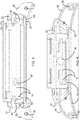
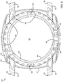
- Fig. 1 is a perspective view of an exemplary watch case middle 10 produced in accordance with the method of the present invention.
- Middle 10 has an outer peripheral surface 12, which in this example has four slightly rounded sides, and an inner peripheral surface 14 defining a generally cylindrical-shaped opening 16 in which a watch movement (not shown) can be housed.
- the profile of inner peripheral surface 14 includes a series of projections and grooves for securely holding the watch movement cage.
- Middle 12 further has a bottom surface 20 onto which a watch case back (not shown) can be fitted, and a top surface 22.
- Top surface 22 includes profiled surface areas 22 and 24 that include a series of channels and flange-like projections.
- the latter are designed to receive and fit a bezel and a glass crystal in conventional manner; again neither the bezel nor the crystal is shown in the drawings.
- Sealing joints such as O-rings are generally interposed between the middle 10 and each of the other components of the watch case during assembly.
- Case middle 10 further includes two pairs of projecting lugs 30, with each pair being destined to receive an end of a watch strap or bracelet.
- Each lug 30 has a hole 32 for fixing the end of the bracelet to the lugs by any suitable manner, for example using a bar and screws. It will however be appreciated that in some bracelet-fastening systems, no holes are needed to secure a bracelet to a watch case.
- a through hole 40 for receiving the stem of a watch control member notably a setting crown (not shown) extends through the middle 10 into cavity 16.
- a similar through hole 42 extends through the middle and is designed to receive the stem of a pusher button (not shown).
- the surface 12 also includes two indentations 46, on each side of through hole 40, for receiving the feet of a crown-covering bridge (not shown) such as the well-known bridge used in Panerai Luminor® watches.
- blind threaded holes 44 are formed to receive screws that will fix the crown-covering bridge to case middle 10 after the crown control member has been mounted.
- Case middle 10 though formed in a unitary manner, has at least one internal cavity 50 formed within it.
- the weight of the case middle and the amount of material it contains can be greatly reduced.
- case middle 10 comprises at least 25% less material (and hence weighs at least 25% less) than a solid middle having the same external geometry but no internal cavities. More preferably, the reduction in weight and amount of material used for the middle is at least 40%. As described in more detail below in connection with Fig. 8 , this reduction is achieved by building the case middle 10, using an additive manufacturing process in which an energy source is used to unify, i.e., solidify or bond, layers of powdered material to one on top of another.
- the method of the present invention is particularly applicable to watch cases made from metals and alloys thereof, it may also be used to produce watch cases from any powdered material (for example powders for ceramics or elastomers) that can be fused, melted or otherwise united together by way of an additive manufacturing process.
- the method is especially advantageous for producing cases made of metals that are relatively heavy (such as stainless steel) and/or expensive (such as gold and platinum).
- Other watch case powdered materials such as Cobalt Chromium and Titanium alloys may also be used.
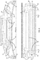
- Figs. 2-7 illustrate the internal geometry of case middle 10. More particularly, Fig. 2 is a perspective section view taken along the plane II-II in Fig. 1 looking downward toward the back side 2- of the case middle according to one embodiment. Figs. 3-7 are perspective section views taken respectively along the lines III-III, IV-IV, V-V, VI-VI, and VII-VII in Fig. 2 .
- middle 10 is formed throughout by walls 52 that have been unitarily formed, layer by layer, from one or more desired powdered materials. Walls 52 define at least one internal cavity while also surrounding holes 40, 42, 44 and 32 that are formed through or within the case middle. (It should be noted that although the location of bracelet fixation through holes 32 is shown for clarity in Fig. 2 , they do not lie in the section plane II-II.).
- case middle 10 comprises a single contiguous internal cavity 50 that generally extends circularly around the middle between surfaces 12 and 14 as well as into lugs 30.
- the internal shape and geometry of the cavity can vary depending on the external profile of the case middle and the thickness of walls 52. The latter depends, in turn, partly on the type of powder material used and the strength of the resulting unified material.
- at least one powder evacuation hole 60, 62 is also formed in order to enable excess or loose powder to be removed from the cavity after the building of the layers is complete.
- three such powder evacuation holes 60 are formed between the bottom surface 20 of middle 10 (which receives the watch case back) and the cavity 50.
- a further powder evacuation hole 62 ( Fig. 1 ) is formed between the top surface 22 of middle 10 (more particularly the area 24 of surface 22 that receives the bezel) and the cavity 50.
- the purpose and role of holes 60, 62 are described further below.
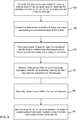
- a method for producing a watch case middle in accordance with a preferred embodiment of the invention is now described.
- a three-dimensional (3-D) data set of the watch case middle 10 is generated based on its desired physical parameters, in particular the shapes and sizes of the surfaces 12,14, 20, and 22 and the location of holes 40, 42, 44 and 32.
- 3-D computer-aided-design (CAD) data models can be generated using programs such as SolidWorks®.
- CAD computer-aided-design
- a data modeling tool specific to the additive manufacturing process and/or machine being used to form case middle 10 may be used. Such a tool may notably convert a CAD data model to a data set format suitable for use by the additive manufacturing machine.
- the 3-D data set for watch middle 10 notably models the configuration of internal cavity 50, including the material that forming the cavity walls 52 that surround control member stem through holes 40 and 42, screw holes 44, and bracelet fixation holes 32. Where the middle includes several non-contiguous internal cavities, the cavity walls separating each of these are also included in the model.
- the 3-D data set may include from the outset the formation of holes 40, 42, 44 and 32; in this case, as described further below, these holes are designed in the data model to have slightly smaller dimensions than what is finally desired.
- the 3-D data set can include thicker solid cavity wall portions 52 that extend throughout the entire region of the middle in which holes 40, 42, 44 and 32 are to be formed, and those holes are then formed entirely during a subsequent machining step, after to the layer-by-layer building of middle 10.
- powder evacuation holes 60 and 62 may be formed initially as part of the 3-D data set information (e.g., by modifying a CAD data model to account for them), or they may alternatively be formed as part of a post-machining step.
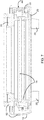
- the cavity 50 may further include a support structures 54 in order to strengthen case middle 10.
- Fig. 9 is a perspective section view taken along the plane II-II in Fig. 1 , and apart from the presence of support structures 54, case middle 10' of Fig. 9 is essentially identical to case middle 10 of Fig. 2 .
- the support structures 54 are pillar-like elements disposed throughout cavity 50, each extending from the bottom of case middle to the top.
- support structures may be arranged and may extend in any structurally appropriate manner.
- internal cavity support structures may have a grid-like arrangement or they may extend in parallel to the plane II-II similar to beams. Support structures may especially be desirable where the cavity walls 52 are designed to be very thin.
- support structures 54 are built within the cavity of the case middle, they are included in the 3-D data set at step 80.
- the additive manufacturing machine or a related tool may, for example, automatically determine the location, size, and geometry for the support structures 54 and/or powder evacuation holes 60, 62 based on a set of criteria or instruction input by a user.
- the additive manufacturing machine or tool can automatically supplement and modify the initial user-specified data for the middle to generate a final 3-D data set to be used in the additive manufacturing process as described below.
- the generation of a 3-D data set that includes all of the above described features in a manner that optimizes both weight reduction and structural integrity generally depends on a number of factors including the shape of the case middle and its various parts, the type of powder material used and the strength of the resulting unitary material.
- the flexibility of additive manufacturing processes enables any specific area of the case middle geometry to be reinforced without changing the middle's overall design. For example, if it is determined that there is a weak areas in a specific section of a wall, that section of the wall can be made thicker or an appropriate support structure can be readily added in.
- the 3-D data set for middle 10 is converted at step 82 into a plurality of layers, each layer representing a cross-sectional layer of the middle.
- These layers will be formed one onto the other using an additive manufacturing machine and process described below, and the conversion is typically carried out by the additive manufacturing machine or a related software tool thereof.
- this conversion occurs so that the layers run in parallel manner along an axis perpendicular to the face of the watch (i.e., to plane II-II), extending from the bottom surface 20 to the top surface 22.
- the layers preferably have a thickness in the range 1 -100 ⁇ m, and they may be of equal thickness or different thicknesses. For example, for a watch case middle having a height of approximately 1 cm, and using a uniform layer thickness of 20 ⁇ m, the 3-D data set would be converted into around 500 layers.
- case middle 10 is formed layer-by-layer using an additive manufacturing process (also sometime called a rapid manufacturing process).
- an energy source such as a laser or an electron beam is used to unite (i.e., to solidify, fuse or bond) layers of powdered material together.
- laser-based additive manufacturing is accomplished by directing a high power laser at a substrate or platform to create a melt pool.
- DMLS direct metal laser sintering
- each layer is formed by depositing a uniformly thick layer of powdered material across an entire build area.
- the powder in specific areas is then selectively melted by the laser so that those areas fuse to the immediately preceding layer of fused material (that is present in solid form underneath the powder layer). Additional information on additive manufacturing is found in the " Wohlers Report 2010 -- Additive Manufacturing State of the Industry", Annual Worldwide Progress Report, Terry Wohlers, ISBN 0-9754429-6-1 .
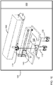
- Fig. 10 is a diagram illustrating the main parts of a DMLS machine 100, such as the EOSINT M270 machine from EOS GmbH, suitable for building case middle 10.
- machine 100 includes a building platform 110 onto which the case middle is manufactured. Platform 110 can be successively lowered as the fusing of powder to produce each layer is completed. In this manner, the building of each layer occurs at the same vertical position within machine 100.
- a powder reservoir 120 cooperates with a dispenser platform 130 and a recoating system 140 to evenly dispense metal powder during the building/processing of each layer.
- the energy source module includes a laser 150, a series of mirrors 160, and a galvanometer-scanner with f-Theta lens 170 and is precisely controlled in response to the final 3-D dataset that is used by the machine's control system 180.
- case middle 10 may also be built using an electron beam melting (EBM) or an ultrasonic consolidation (UC) additive manufacturing process.
- EBM electron beam melting
- UC ultrasonic consolidation
- powder evacuation holes 60 and 62 were included in the final 3-D data set and therefore were formed during additive manufacturing at step 84, then, at step 86, loose powder remaining in each cavity is removed via the one or more powder evacuation holes 60, 62 formed between that cavity and an external surface of the middle. This may be accomplished in different manners; for example by using suction or by blowing into a first powder evacuation hole so that powder exits from a second powder evacuation hole. On the other hand, if the powder evacuation holes were not included in the 3-D data set, then they may be formed by a machining step once the additive manufacturing at step 84 is complete.
- the powder evacuation holes are preferably in locations that will subsequently be covered and sealed by other components of the watch case, e.g., on an area of surface 20 that will be covered by the watch back and/or an area of surface 22 that will receive the bezel.
- Holes 60, 62 may also be subsequently filled in after removing powder in order to eliminate the possibility of any remaining loose powder interfering with the watch mechanisms and/or to prevent the powder from possibly affecting the robustness of the case middle.
- Holes 60, 62 may be filled by, for example, welding the hole shut. However, even when filled, it is preferred that the powder evacuation hole sites remain hidden when the watch case is finally assembled.
- a thermal treatment step is next preferably carried out on the case middle.
- the duration and temperature of the thermal treatment may vary depending on the nature of the powdered material.
- This step may provide stress relief within the case middle structure as well as other potential structural benefits. However, stress relief may not be necessary in some instances or it may be achieved by alternative means, for instance using vibratory stress relief.
- Case middle 10 may also at this stage be separated, e.g. mechanically, from the platform 110 of machine 10. However, separation could alternatively occur prior to the loose powder removal step or at a later stage.
- holes 40, 42, 44, and 32 are machined to obtain a desired surface finish and/or precision throughout the holes.
- holes 40, 42, 44, and 32 may be completely formed using conventional machining tools at this step 90, in which case the 3-D data set includes thick cavity wall portions 52 that extend throughout the entire region of the middle in which holes 40, 42, 44 and 32 are to be formed.
- the 3-D data set may include an initial pre-form of holes 40, 42, 44 and 32, but where they are designed to have slightly smaller dimensions than those that are ultimately necessary in the final case middle 10.
- the machining step at 90 is still carried out to arrive at the desired surface finish and/or precision throughout holes 40, 42, 44 and 32.
- the former option may be preferred especially when hard materials are used, since drilling or milling through an already existing hole (as opposed to solid material) may cause tools to fail prematurely.
- drilling or milling through an already existing hole as opposed to solid material
- tools to fail prematurely may be difficult to be achieved.
- the latter option although it is envisaged that in the future additive manufacturing processes will enable the thickness of the layers to be reduced and hence for a better overall precision of the features of case middle to be achieved, it is believed that the ability of the additive manufacturing process to finely control surface finish (i.e., roughness) and/or surface roundness will remain inferior to what can be achieved using machining tools.
- Additional precision machining steps are also preferably carried out on the areas of surfaces 20 and 22 destined to receive the back and the bezel of the watch case.
- a final step of finishing e.g., polishing
- the external surface of the middle - or at least that part that will remain visible once the watch is fully assembled - is carried out prior to assembling the watch case.
- a watch case middle produced by the method of the present invention continues to have a strong, resilient and unitary construction despite using less material and having a significantly reduced weight.
- the middle can subsequently be used with a case back, bezel and crystal to assemble a watch case that houses a watch movement.
- the method of the present invention greatly facilitates the construction of watch case middles having varied and complex geometries.
- the method may also be adapted to produce other light-weight external watch components; in particular bracelet links that are conventionally made of solid metal but that could instead be produced with an internal cavity using an additive manufacturing process.
Landscapes
- Engineering & Computer Science (AREA)
- Physics & Mathematics (AREA)
- Chemical & Material Sciences (AREA)
- Manufacturing & Machinery (AREA)
- Materials Engineering (AREA)
- General Physics & Mathematics (AREA)
- Optics & Photonics (AREA)
- Mechanical Engineering (AREA)
- Powder Metallurgy (AREA)
- Electric Clocks (AREA)
Description
- The present invention relates to a method for producing a watch case and in particular a watch case middle having reduced weight.
- A watch case typically comprises four main components: a middle, a crystal, a bezel surrounding the crystal fitted on top of the middle, and a back fitted underneath the middle. The bezel and the middle may in some cases be formed as a single piece, and the middle also typically includes two pairs of projecting lugs that enable the case to be attached to a watch strap or bracelet. The case middle surrounds the watch movement. It is typically made from solid metal material, and the middle is generally the most massive of the watch case components by far.
- In order to reduce the amount of material used in a watch case and hence also the weight of the case and the cost of the material used to produce it (particularly in the case of precious metals), it has been proposed to hollow out the middle. For example,
EP626625 - Similarly, in
CH664251 - Unfortunately, such prior art solutions for producing hollowed-out watch case middles generally result in watch cases that are of significantly reduced strength and that require complex assembly. In addition, because the middle is not unitarily formed, the watch case may suffer from reduced sealing or watertightness compared to a conventional watch case. Furthermore, where a massive middle is initially produced and then subsequently hollowed-out, there may be a significant amount of material wasted that cannot be readily reused.
- There is consequently a need to provide a reduced weight watch case and in particular a watch case middle for which the above-mentioned shortcomings are alleviated.
-
US2010290319 discloses a method for producing a mechanical clock using standard CAD modelling tools and a rapid prototyping machine. Once the support material is removed, the clock runs without any additional assembly. In this implementation, the clock contains all the components that are required and they are all constructed in the rapid prototyping process. -
EP074040 -
US2004155384 relates to the production of a work piece with exact geometry and high surface quality using a process wherein powder coatings are applied one on top of each other, by means of compaction, said process being computer-controlled. After the powder has been compacted, the surfaces thereof are finely machined in a mechanical manner. During the entire machining process, the work piece to be produced is surrounded with powdery source material. - The on-line document retrievable at https://www.thingiverse.com/thing:1812 shows a watch case made by a 3-D dataset and printing method.
- The present invention addresses the above-described disadvantages of the prior art by providing a method for producing a watch case middle according to claim 1.
- The case middle has reduced weight and a 3-D data set is generated for the case middle, the model comprising at least one internal cavity within the case middle. The 3-D data set is converted into a plurality of layers, each layer representing a cross-sectional layer of the middle, and then the case middle is formed layer-by-layer from powdered material using an additive manufacturing process such as DMLS in order to provide the case middle with a unitary construction. The layers can have a thickness in the range 1 -100 µm. Loose powder is removed from each cavity via one or more powder evacuation holes formed between the cavity and an external surface of the case middle, and a through hole formed through the middle is machined to a desired finish and/or precision, the through hole being designed to receive a control member stem when a watch movement is mounted inside the middle.
- In an embodiment, the one or more powder evacuation holes can be formed by machining said holes after the case middle has been formed. After removing loose powder, the one or more powder evacuation holes can be filled.
- In another embodiment, the additive manufacturing process can comprise direct metal laser sintering or an electron beam melting additive manufacturing process.
- In yet another embodiment, the method can further comprise machining areas of a bottom surface and a top surface of the case middle that are respectively destined to receive a case back and a bezel of a watch case and possibly finishing the external surface of the case middle, and possibly subjecting the case middle to thermal treatment after removing loose powder from each cavity and before machining the through hole to a desired finish and/or precision.
- The watch case middle comprises an outer peripheral surface and an inner peripheral surface defining an opening for housing a watch movement, in which the case middle comprises at least one internal cavity that extends around the case middle between the inner and outer peripheral surfaces. The case middle may comprise at least 25% less material than a solid case middle having the same external geometry but no internal cavities. The case middle is formed layer-by-layer from powdered material using an additive manufacturing process such that the case middle has a unitary construction throughout.
- These and other embodiments and variations are described further below.
- The objects and advantages of the present invention will be better understood and more readily apparent when considered in conjunction with the following detailed description and accompanying drawings which illustrate, by way of example, preferred embodiments of the invention and in which:
-
Fig. 1 is a perspective view of a watch case middle produced in accordance with the method of the present invention; -
Fig. 2 is a perspective section view taken along the plane II-II inFig. 1 looking downward toward the back of the case middle in one embodiment; -
Fig. 3 is a perspective section view taken along the line III-III inFig. 2 ; -
Fig. 4 is a perspective section view taken along the line IV-IV inFig. 2 ; -
Fig. 5 is a perspective section view taken along the line V-V inFig. 2 ; -
Fig. 6 is a perspective section view taken along the line VI-VI inFig. 2 ; -
Fig. 7 is a perspective section view taken along the line VII-VII inFigure 2 ; -
Fig. 8 is a flow diagram illustrating a method for producing a watch case middle in accordance with an embodiment of the invention; -
Fig. 9 is a perspective section view taken along the plane II-II inFig. 1 looking downward toward the back of the case middle in another embodiment; and -
Fig. 10 is a diagram of an exemplary additive manufacturing machine suitable for use in the method ofFig. 8 . -
Fig. 1 is a perspective view of an exemplarywatch case middle 10 produced in accordance with the method of the present invention. Middle 10 has an outerperipheral surface 12, which in this example has four slightly rounded sides, and an innerperipheral surface 14 defining a generally cylindrical-shaped opening 16 in which a watch movement (not shown) can be housed. In known manner, the profile of innerperipheral surface 14 includes a series of projections and grooves for securely holding the watch movement cage. Middle 12 further has abottom surface 20 onto which a watch case back (not shown) can be fitted, and atop surface 22.Top surface 22 includes profiledsurface areas middle 10 and each of the other components of the watch case during assembly. -
Case middle 10 further includes two pairs of projectinglugs 30, with each pair being destined to receive an end of a watch strap or bracelet. Eachlug 30 has ahole 32 for fixing the end of the bracelet to the lugs by any suitable manner, for example using a bar and screws. It will however be appreciated that in some bracelet-fastening systems, no holes are needed to secure a bracelet to a watch case. - On one side of
outer surface 12, athrough hole 40 for receiving the stem of a watch control member notably a setting crown (not shown) extends through themiddle 10 intocavity 16. A similar through hole 42 (Fig. 2 ) extends through the middle and is designed to receive the stem of a pusher button (not shown). In the illustrated example ofFig. 1 , thesurface 12 also includes twoindentations 46, on each side of throughhole 40, for receiving the feet of a crown-covering bridge (not shown) such as the well-known bridge used in Panerai Luminor® watches. Within theindentations 46, blind threadedholes 44 are formed to receive screws that will fix the crown-covering bridge to case middle 10 after the crown control member has been mounted. - Case middle 10, though formed in a unitary manner, has at least one
internal cavity 50 formed within it. As noted above, depending on the size of the cavity or cavities, the weight of the case middle and the amount of material it contains can be greatly reduced. Preferably case middle 10 comprises at least 25% less material (and hence weighs at least 25% less) than a solid middle having the same external geometry but no internal cavities. More preferably, the reduction in weight and amount of material used for the middle is at least 40%. As described in more detail below in connection withFig. 8 , this reduction is achieved by building the case middle 10, using an additive manufacturing process in which an energy source is used to unify, i.e., solidify or bond, layers of powdered material to one on top of another. - While the method of the present invention is particularly applicable to watch cases made from metals and alloys thereof, it may also be used to produce watch cases from any powdered material (for example powders for ceramics or elastomers) that can be fused, melted or otherwise united together by way of an additive manufacturing process. The method is especially advantageous for producing cases made of metals that are relatively heavy (such as stainless steel) and/or expensive (such as gold and platinum). Other watch case powdered materials such as Cobalt Chromium and Titanium alloys may also be used.
-
Figs. 2-7 illustrate the internal geometry of case middle 10. More particularly,Fig. 2 is a perspective section view taken along the plane II-II inFig. 1 looking downward toward the back side 2- of the case middle according to one embodiment.Figs. 3-7 are perspective section views taken respectively along the lines III-III, IV-IV, V-V, VI-VI, and VII-VII inFig. 2 . As shown, middle 10 is formed throughout bywalls 52 that have been unitarily formed, layer by layer, from one or more desired powdered materials.Walls 52 define at least one internal cavity while also surroundingholes holes 32 is shown for clarity inFig. 2 , they do not lie in the section plane II-II.). - In the illustrated embodiment, case middle 10 comprises a single contiguous
internal cavity 50 that generally extends circularly around the middle betweensurfaces lugs 30. The internal shape and geometry of the cavity can vary depending on the external profile of the case middle and the thickness ofwalls 52. The latter depends, in turn, partly on the type of powder material used and the strength of the resulting unified material. For each cavity, at least onepowder evacuation hole bottom surface 20 of middle 10 (which receives the watch case back) and thecavity 50. A further powder evacuation hole 62 (Fig. 1 ) is formed between thetop surface 22 of middle 10 (more particularly thearea 24 ofsurface 22 that receives the bezel) and thecavity 50. The purpose and role ofholes - Referring now to the flow diagram of
Fig. 8 , a method for producing a watch case middle in accordance with a preferred embodiment of the invention is now described. At afirst step 80, a three-dimensional (3-D) data set of the watch case middle 10 is generated based on its desired physical parameters, in particular the shapes and sizes of thesurfaces holes internal cavity 50, including the material that forming thecavity walls 52 that surround control member stem throughholes - Optionally, the 3-D data set may include from the outset the formation of
holes cavity wall portions 52 that extend throughout the entire region of the middle in which holes 40, 42, 44 and 32 are to be formed, and those holes are then formed entirely during a subsequent machining step, after to the layer-by-layer building of middle 10. In a similar manner, powder evacuation holes 60 and 62may be formed initially as part of the 3-D data set information (e.g., by modifying a CAD data model to account for them), or they may alternatively be formed as part of a post-machining step. - In an alternative embodiment of a case middle 10' illustrated in
Fig. 9 , thecavity 50 may further include asupport structures 54 in order to strengthen case middle 10.Fig. 9 is a perspective section view taken along the plane II-II inFig. 1 , and apart from the presence ofsupport structures 54, case middle 10' ofFig. 9 is essentially identical to case middle 10 ofFig. 2 . In the example ofFig. 9 , thesupport structures 54 are pillar-like elements disposed throughoutcavity 50, each extending from the bottom of case middle to the top. In general, however, support structures may be arranged and may extend in any structurally appropriate manner. For example, internal cavity support structures may have a grid-like arrangement or they may extend in parallel to the plane II-II similar to beams. Support structures may especially be desirable where thecavity walls 52 are designed to be very thin. Wheresupport structures 54 are built within the cavity of the case middle, they are included in the 3-D data set atstep 80. - It will be appreciated that the additive manufacturing machine or a related tool may, for example, automatically determine the location, size, and geometry for the
support structures 54 and/or powder evacuation holes 60, 62 based on a set of criteria or instruction input by a user. In this case, the additive manufacturing machine or tool can automatically supplement and modify the initial user-specified data for the middle to generate a final 3-D data set to be used in the additive manufacturing process as described below. More generally, the generation of a 3-D data set that includes all of the above described features in a manner that optimizes both weight reduction and structural integrity generally depends on a number of factors including the shape of the case middle and its various parts, the type of powder material used and the strength of the resulting unitary material. At the same time, the flexibility of additive manufacturing processes enables any specific area of the case middle geometry to be reinforced without changing the middle's overall design. For example, if it is determined that there is a weak areas in a specific section of a wall, that section of the wall can be made thicker or an appropriate support structure can be readily added in. - Once the 3-D data set for middle 10 is fully generated, it is converted at
step 82 into a plurality of layers, each layer representing a cross-sectional layer of the middle. These layers will be formed one onto the other using an additive manufacturing machine and process described below, and the conversion is typically carried out by the additive manufacturing machine or a related software tool thereof. Preferably, this conversion occurs so that the layers run in parallel manner along an axis perpendicular to the face of the watch (i.e., to plane II-II), extending from thebottom surface 20 to thetop surface 22. The layers preferably have a thickness in the range 1 -100 µm, and they may be of equal thickness or different thicknesses. For example, for a watch case middle having a height of approximately 1 cm, and using a uniform layer thickness of 20 µm, the 3-D data set would be converted into around 500 layers. - As shown at
step 84, case middle 10 is formed layer-by-layer using an additive manufacturing process (also sometime called a rapid manufacturing process). In this type of process, an energy source such as a laser or an electron beam is used to unite (i.e., to solidify, fuse or bond) layers of powdered material together. For example, laser-based additive manufacturing is accomplished by directing a high power laser at a substrate or platform to create a melt pool. In particular, the direct metal laser sintering (DMLS) process, which was developed by EOS GmbH in Germany and is designed to sinter or fuse pre-alloyed powdered metals, is particularly suitable for producing metal watch case middles in accordance with the present invention. In DMLS, each layer is formed by depositing a uniformly thick layer of powdered material across an entire build area. The powder in specific areas is then selectively melted by the laser so that those areas fuse to the immediately preceding layer of fused material (that is present in solid form underneath the powder layer). Additional information on additive manufacturing is found in the "Wohlers Report 2010 -- Additive Manufacturing State of the Industry", Annual Worldwide Progress Report, Terry Wohlers, ISBN 0-9754429-6-1. -
Fig. 10 is a diagram illustrating the main parts of aDMLS machine 100, such as the EOSINT M270 machine from EOS GmbH, suitable for building case middle 10. As shown,machine 100 includes abuilding platform 110 onto which the case middle is manufactured.Platform 110 can be successively lowered as the fusing of powder to produce each layer is completed. In this manner, the building of each layer occurs at the same vertical position withinmachine 100. Apowder reservoir 120 cooperates with adispenser platform 130 and arecoating system 140 to evenly dispense metal powder during the building/processing of each layer. The energy source module includes alaser 150, a series ofmirrors 160, and a galvanometer-scanner with f-Theta lens 170 and is precisely controlled in response to the final 3-D dataset that is used by the machine'scontrol system 180. - More generally however, while a
DMLS machine 100 is shown, any suitable additive manufacturing process that directs an energy source to unite, i.e., solidify or bond, layers of powdered material together to provide a unitary case middle construction may be used. For example, case middle 10 may also be built using an electron beam melting (EBM) or an ultrasonic consolidation (UC) additive manufacturing process. - If powder evacuation holes 60 and 62 were included in the final 3-D data set and therefore were formed during additive manufacturing at
step 84, then, atstep 86, loose powder remaining in each cavity is removed via the one or more powder evacuation holes 60, 62 formed between that cavity and an external surface of the middle. This may be accomplished in different manners; for example by using suction or by blowing into a first powder evacuation hole so that powder exits from a second powder evacuation hole. On the other hand, if the powder evacuation holes were not included in the 3-D data set, then they may be formed by a machining step once the additive manufacturing atstep 84 is complete. - It will be appreciated that the powder evacuation holes are preferably in locations that will subsequently be covered and sealed by other components of the watch case, e.g., on an area of
surface 20 that will be covered by the watch back and/or an area ofsurface 22 that will receive the bezel.Holes Holes - At
step 88, a thermal treatment step is next preferably carried out on the case middle. The duration and temperature of the thermal treatment may vary depending on the nature of the powdered material. This step may provide stress relief within the case middle structure as well as other potential structural benefits. However, stress relief may not be necessary in some instances or it may be achieved by alternative means, for instance using vibratory stress relief. Case middle 10 may also at this stage be separated, e.g. mechanically, from theplatform 110 ofmachine 10. However, separation could alternatively occur prior to the loose powder removal step or at a later stage. - Subsequently, at
step 90, holes 40, 42, 44, and 32 are machined to obtain a desired surface finish and/or precision throughout the holes. As indicated above, holes 40, 42, 44, and 32 may be completely formed using conventional machining tools at thisstep 90, in which case the 3-D data set includes thickcavity wall portions 52 that extend throughout the entire region of the middle in which holes 40, 42, 44 and 32 are to be formed. Alternatively, the 3-D data set may include an initial pre-form ofholes holes - Additional precision machining steps are also preferably carried out on the areas of
surfaces - In this manner, a watch case middle produced by the method of the present invention continues to have a strong, resilient and unitary construction despite using less material and having a significantly reduced weight. In known manner, the middle can subsequently be used with a case back, bezel and crystal to assemble a watch case that houses a watch movement. As a further advantage, the method of the present invention greatly facilitates the construction of watch case middles having varied and complex geometries. Moreover, the method may also be adapted to produce other light-weight external watch components; in particular bracelet links that are conventionally made of solid metal but that could instead be produced with an internal cavity using an additive manufacturing process.
- While the invention has been described in conjunction with specific embodiments, it is evident that numerous alternatives, modifications, and variations will be apparent to those skilled in the art in light of the foregoing description, without departing from the scope of the invention as defined by the appended claims.
Claims (12)
- A method for producing a watch case middle (10) having reduced weight, comprising:generating a 3-D dataset for the case middle (10), the case middle comprising an outer peripheral surface (12), an inner peripheral surface (14), a bottom surface (20) and a top surface (22);converting the 3-D data set into a plurality of layers, each layer representing a cross-sectional layer of the middle (10);forming the case middle (10) layer-by-layer from powdered material using an additive manufacturing process in order to provide the case middle (10) with a unitary construction; andmachining a through hole (40, 42) formed through the middle (10) to a desired finish and/or precision, the through hole being designed to receive a control member stem when a watch movement is mounted inside the middle;wherein the data set further comprises at least one internal cavity (50) within the case middle (10) so that the case middle (10) has the least one internal cavity (50) formed within it, the method further comprising removing loose powder from each cavity (50) via one or more powder evacuation holes (60, 62) formed between the at least one internal cavity (50) and an external surface of the case middle (10), wherein one or more powder evacuation holes (60, 62) are formed between the bottom surface (20) of the middle (10) and the cavity (50), wherein the bottom surface (20) is destined to receive a watch case back.
- The method according to claim 1, wherein the outer peripheral surface (12) and the inner peripheral surface (14) define a generally cylindrical-shaped opening (16) for housing the watch movement, and the at least one internal cavity (50) extend or extends circularly around the middle (10) between the inner and outer peripheral surfaces (14, 12).
- The method according to claim 2, wherein the case middle (10) further includes two pairs of lugs (30) projecting from the outer peripheral surface (12), each pair of lugs (30) being destined to receive an end of a watch strap or bracelet, and the at least one internal cavity (50) further extending into the lugs (30).
- The method according to any preceding claim, wherein the 3-D dataset includes an initial pre-formation of the through hole (40, 42) for receiving the control member stem, the dimensions of the pre-formed through hole in the 3-D dataset being smaller than the final dimensions of the through hole (40, 42), the 3-D dataset further including the formation of walls (52) surrounding the through hole.
- The method according to one of claims 1 to 3, where in the 3-D dataset includes solid cavity wall portions (52) that extend throughout the entire region of the middle (10) in which the through hole (40, 42) for receiving the control member stem is to be formed, and the through hole is formed entirely during the step of machining the through hole (40, 42).
- The method according to any preceding claim, wherein the 3-D dataset includes a plurality of internal cavities (50) within the case middle (10) and walls (52) separating those cavities.
- The method according to any preceding claim, wherein the 3-D dataset further includes support structures (54) located within the at least one internal cavity (50) for strengthening the case middle (10).
- The method according to any preceding claim, wherein the 3-D dataset includes the formation of the one or more powder evacuation holes (60, 62).
- The method according to one of claims 1 to 7, wherein the one or more powder evacuation holes (60, 62) are formed by machining said holes after the case middle (10) has been formed.
- The method according to any preceding claim, wherein three powder evacuation holes (60, 62) are formed between a bottom surface (20) of middle (10) and the cavity (50), wherein the bottom surface (20) is destined to receive a watch case back.
- The method according to any preceding claim, wherein a further powder evacuation hole (62) is formed between an area (24) of the top surface (22) of middle (10) and the cavity (50), wherein the area (24) is destined to receive a bezel.
- The method according to any preceding claim, wherein the case middle (10) is formed layer-by-layer on a platform (110), and the method further comprises separating the case middle from the platform after the case middle has been formed.
Applications Claiming Priority (1)
| Application Number | Priority Date | Filing Date | Title |
|---|---|---|---|
| US13/019,484 US8689446B2 (en) | 2011-02-02 | 2011-02-02 | Method for producing a watch case middle of reduced weight |
Publications (3)
| Publication Number | Publication Date |
|---|---|
| EP2485099A2 EP2485099A2 (en) | 2012-08-08 |
| EP2485099A3 EP2485099A3 (en) | 2013-08-28 |
| EP2485099B1 true EP2485099B1 (en) | 2020-09-02 |
Family
ID=45557962
Family Applications (1)
| Application Number | Title | Priority Date | Filing Date |
|---|---|---|---|
| EP12153503.3A Active EP2485099B1 (en) | 2011-02-02 | 2012-02-01 | Method for producing a watch case middle of reduced weight |
Country Status (3)
| Country | Link |
|---|---|
| US (1) | US8689446B2 (en) |
| EP (1) | EP2485099B1 (en) |
| CN (1) | CN102699332B (en) |
Cited By (1)
| Publication number | Priority date | Publication date | Assignee | Title |
|---|---|---|---|---|
| EP4372484A1 (en) | 2022-11-16 | 2024-05-22 | Richemont International S.A. | Hollow middle for a timepiece case and corresponding manufacturing method |
Families Citing this family (25)
| Publication number | Priority date | Publication date | Assignee | Title |
|---|---|---|---|---|
| US9452840B2 (en) | 2014-04-15 | 2016-09-27 | The Boeing Company | Monolithic part and method of forming the monolithic part |
| USD748995S1 (en) * | 2014-08-01 | 2016-02-09 | Nixon Inc. | Watch |
| CN104570693B (en) * | 2014-12-15 | 2017-10-31 | 深圳金王金技术开发有限公司 | Hollow watch watchcase |
| CN104597743A (en) * | 2015-01-21 | 2015-05-06 | 简琮和 | gold watch |
| USD782337S1 (en) * | 2015-12-04 | 2017-03-28 | Nixon, Inc. | Watch |
| USD782338S1 (en) * | 2015-12-04 | 2017-03-28 | Nixon, Inc. | Watch |
| EP3181515A1 (en) * | 2015-12-15 | 2017-06-21 | CSEM Centre Suisse d'Electronique et de Microtechnique SA - Recherche et Développement | Composite timepiece and method for manufacturing same |
| USD784166S1 (en) * | 2015-12-16 | 2017-04-18 | Seiko Watch Kabushiki Kaisha | Watch case |
| JP2017201296A (en) * | 2016-05-02 | 2017-11-09 | セイコーエプソン株式会社 | Electronic clock |
| EP3323530A1 (en) | 2016-11-16 | 2018-05-23 | Montfort Watches SA | 3d printed watch dial |
| JP6562277B2 (en) * | 2017-04-10 | 2019-08-21 | カシオ計算機株式会社 | Case and watch |
| US11292058B2 (en) * | 2017-09-12 | 2022-04-05 | Divergent Technologies, Inc. | Apparatus and methods for optimization of powder removal features in additively manufactured components |
| USD847662S1 (en) * | 2017-10-17 | 2019-05-07 | Richemont International Sa | Watch case |
| USD854947S1 (en) * | 2017-10-17 | 2019-07-30 | Richemont International Sa | Watch |
| EP3572209B1 (en) * | 2018-05-24 | 2021-12-29 | The Swatch Group Research and Development Ltd | Watch or jewelery component made of composite material and method for manufacturing same |
| EP3672114A1 (en) * | 2018-12-21 | 2020-06-24 | Montres Rado S.A. | Method and system for transmission of at least one message by means of a timepiece |
| IT201900012993A1 (en) * | 2019-07-26 | 2021-01-26 | Univ Degli Studi Di Brescia | RE-DESIGN OF THE MECHANICAL MOVEMENT OF A MANUAL WINDING WATCH |
| EP3822712A1 (en) * | 2019-11-13 | 2021-05-19 | Rolex Sa | Component for a timepiece |
| EP3926413A1 (en) * | 2020-06-17 | 2021-12-22 | Rubattel et Weyermann S.A. | Formation of a three-dimensional object on a dial |
| EP3964895A1 (en) * | 2020-09-04 | 2022-03-09 | Comadur S.A. | Method for manufacturing a part from hard material with a polymer insert |
| CN114603175A (en) * | 2020-12-05 | 2022-06-10 | 惠州市鑫瑞高精密有限公司 | Watch case processing method |
| CN112842634A (en) * | 2021-02-26 | 2021-05-28 | 重庆熙科医疗科技有限公司 | Non-fixed hollow talus prosthesis and forming method |
| CN218446386U (en) * | 2022-10-28 | 2023-02-03 | 乳圆数字科技(深圳)有限公司 | Metal wheel rotating device |
| WO2024246292A1 (en) * | 2023-06-01 | 2024-12-05 | Rolex Sa | Light-weight and robust timepiece component |
| KR102800933B1 (en) * | 2024-07-26 | 2025-04-29 | 하티스트앤드컴퍼니 주식회사 | A watch protection film fabrication system based on watch model profile data |
Citations (8)
| Publication number | Priority date | Publication date | Assignee | Title |
|---|---|---|---|---|
| EP0074040A2 (en) | 1981-09-04 | 1983-03-16 | Degussa Aktiengesellschaft | Base material consisting of noble metal and glass for ornamentary and every day articles, and process for its production |
| EP0379974A1 (en) | 1989-01-23 | 1990-08-01 | Omega SA | Watch case with a hollow middle part |
| CH684861GA3 (en) | 1992-12-02 | 1995-01-31 | Smh Management Services Ag | Watch case with hollowed-out middle. |
| EP1065576A1 (en) | 1999-06-29 | 2001-01-03 | The Swatch Group Management Services AG | Chronograph watch made of precious metal and with a hollow bezel middle |
| JP2002228771A (en) | 2000-11-30 | 2002-08-14 | Seiko Epson Corp | clock |
| WO2005025783A1 (en) | 2003-09-17 | 2005-03-24 | Particular Ab | Method of producing jewellery and other precious metal products with complex geometries |
| CH700273A1 (en) | 2009-01-26 | 2010-07-30 | Hanspeter Ott | Producing three-dimensional jewelry pieces made of metal, comprises repeatedly applying a metal powder on a substrate and/or highly-adjustable platform in a layer-wise manner, and partially melting the powder layer at a predetermined point |
| US20100290319A1 (en) | 2009-05-13 | 2010-11-18 | Robert Swartz | Methods and Apparatus for Self-Assembled Time-Keeping Device |
Family Cites Families (13)
| Publication number | Priority date | Publication date | Assignee | Title |
|---|---|---|---|---|
| US3664119A (en) * | 1968-08-30 | 1972-05-23 | Ebauches Sa | Calendar electric timepiece |
| US4396289A (en) * | 1980-10-28 | 1983-08-02 | Polaroid Corporation | Method and apparatus for holographic testing of optical components |
| CH675517B5 (en) * | 1989-01-13 | 1991-04-15 | Ebauchesfabrik Eta Ag | |
| CH685465B5 (en) * | 1993-05-28 | 1996-01-31 | Marthe Claude Andre | watch case in noble metal. |
| CN1115881A (en) * | 1994-07-29 | 1996-01-31 | 克劳德安德烈·马撒 | Noble metal watch case |
| US5902441A (en) * | 1996-09-04 | 1999-05-11 | Z Corporation | Method of three dimensional printing |
| US7332537B2 (en) * | 1996-09-04 | 2008-02-19 | Z Corporation | Three dimensional printing material system and method |
| DE69809956T2 (en) * | 1997-09-12 | 2003-04-10 | Engelhard-Clal Uk Ltd., Chessington | METHOD FOR PRODUCING A PRECIOUS METAL WORKPIECE |
| JP2000144489A (en) * | 1998-10-30 | 2000-05-26 | Sumitomo Electric Ind Ltd | Decorative aluminum alloy member and method of manufacturing the same |
| US7153135B1 (en) * | 1999-11-15 | 2006-12-26 | Thomas Richard J | Method for automatically creating a denture using laser altimetry to create a digital 3-D oral cavity model and using a digital internet connection to a rapid stereolithographic modeling machine |
| DE10124795A1 (en) * | 2001-05-21 | 2002-12-12 | Bu St Gmbh Beratungsunternehme | Device and method for producing a workpiece with an exact geometry |
| SE527986C2 (en) * | 2003-09-17 | 2006-07-25 | Particular Ab C O Norlen | Metal powder blend for the production of precious metal products and products |
| CN101607312B (en) * | 2009-07-23 | 2011-09-14 | 华中科技大学 | Material-saving whole fast manufacturing method of metal part |
-
2011
- 2011-02-02 US US13/019,484 patent/US8689446B2/en active Active
-
2012
- 2012-02-01 CN CN201210061708.9A patent/CN102699332B/en active Active
- 2012-02-01 EP EP12153503.3A patent/EP2485099B1/en active Active
Patent Citations (8)
| Publication number | Priority date | Publication date | Assignee | Title |
|---|---|---|---|---|
| EP0074040A2 (en) | 1981-09-04 | 1983-03-16 | Degussa Aktiengesellschaft | Base material consisting of noble metal and glass for ornamentary and every day articles, and process for its production |
| EP0379974A1 (en) | 1989-01-23 | 1990-08-01 | Omega SA | Watch case with a hollow middle part |
| CH684861GA3 (en) | 1992-12-02 | 1995-01-31 | Smh Management Services Ag | Watch case with hollowed-out middle. |
| EP1065576A1 (en) | 1999-06-29 | 2001-01-03 | The Swatch Group Management Services AG | Chronograph watch made of precious metal and with a hollow bezel middle |
| JP2002228771A (en) | 2000-11-30 | 2002-08-14 | Seiko Epson Corp | clock |
| WO2005025783A1 (en) | 2003-09-17 | 2005-03-24 | Particular Ab | Method of producing jewellery and other precious metal products with complex geometries |
| CH700273A1 (en) | 2009-01-26 | 2010-07-30 | Hanspeter Ott | Producing three-dimensional jewelry pieces made of metal, comprises repeatedly applying a metal powder on a substrate and/or highly-adjustable platform in a layer-wise manner, and partially melting the powder layer at a predetermined point |
| US20100290319A1 (en) | 2009-05-13 | 2010-11-18 | Robert Swartz | Methods and Apparatus for Self-Assembled Time-Keeping Device |
Non-Patent Citations (12)
| Title |
|---|
| "Théorie d'Horlogerie", 1 January 1998, article REYMONDIN CHARLES-ANDRE, ET AL: "la Boite", pages: 1 - 5, XP055820175 |
| ANONYMOUS: "Live from La Chaux-de-Fonds – the Cartier manufacture", WATCHPROZINE, 6 May 2010 (2010-05-06), pages 1 - 10, XP055820167, Retrieved from the Internet <URL:https://www.watchprozine.com/cartier/live-from-la-chaux-de-fonds-the-cartier-manufacture/3838926/886/> [retrieved on 20210701] |
| ANONYMOUS: "OMEGA Watches: Design", OMEGA, 7 March 2010 (2010-03-07), pages 1 - 3, XP055820172, Retrieved from the Internet <URL:http://web.archive.org/web/20100307114735/http:/www.omegawatches.com/spirit/watchmaking/design> [retrieved on 20210701] |
| ANONYMOUS: "Watchmaking at Bulgari - Part 4 Bulgari Time in Neuchâtel", WATCHPROZINE, 16 June 2009 (2009-06-16), pages 1 - 21, XP055820169, Retrieved from the Internet <URL:https://www.watchprozine.com/bulgari/watchmaking-at-bulgari-part-4-bulgari-time-in-neuchâtel/3208656/> [retrieved on 20210701] |
| ANONYMOUS: "ZEdit PRO", Z CORPORATION, 4 January 2010 (2010-01-04), pages 1 - 2, XP055820173 |
| C. ANDRÉ: "Modélisation quantitative du procédé de frittage sélectif par laser : relation paramètres/microstructure", EPFL, 2007, pages 1 - 147 |
| CHAPUT: "Fabrication of ceramics by stereolithography", RTEJOURNAL - FORUM FÜR RAPID TECHNOLOGIE, 1 January 2007 (2007-01-01), pages 1 - 15, XP055820162, Retrieved from the Internet <URL:https://www.rtejournal.de/ausgabe4/1163> [retrieved on 20210701] |
| I. GIBSON ET AL.: "Whole book", ADDITIVE MANUFACTURING TECHNOLOGIES - RAPID PROTOTYPING TO DIRECT DIGITAL MANUFACTURING, 2010, pages 1 - 347 |
| MONNERET SERGE: "MicrostÈrÈolithographie de piËces cÈramiques complexes", TECHNIQUES DE L’INGÉNIEUR, 1 January 2004 (2004-01-01), pages 1 - 11, XP055820160, Retrieved from the Internet <URL:https://www.fresnel.fr/perso/monneret/papers/Monneret%20Techn%20Ing%202003.pdf> [retrieved on 20210701] |
| STARNO: "Pocket watch case", 6 July 2010 (2010-07-06), Retrieved from the Internet <URL:https://www.thingiverse.com/thing:1812> [retrieved on 20181001] * |
| SUNHYUNG CHO, ET AL: "Simplicity of the Watch Case Design using Jewel CAD and RP", JOURNAL OF DIGITAL DESIGN, vol. 7, no. 1, 1 January 2007 (2007-01-01), pages 226 - 231, XP055820165 |
| T. GRIMM: "Whole book", USER'S GUIDE TO RAPID PROTOTYPING, 2004, pages 1 - 87 |
Cited By (1)
| Publication number | Priority date | Publication date | Assignee | Title |
|---|---|---|---|---|
| EP4372484A1 (en) | 2022-11-16 | 2024-05-22 | Richemont International S.A. | Hollow middle for a timepiece case and corresponding manufacturing method |
Also Published As
| Publication number | Publication date |
|---|---|
| CN102699332B (en) | 2015-11-25 |
| US20120192424A1 (en) | 2012-08-02 |
| EP2485099A2 (en) | 2012-08-08 |
| EP2485099A3 (en) | 2013-08-28 |
| CN102699332A (en) | 2012-10-03 |
| US8689446B2 (en) | 2014-04-08 |
Similar Documents
| Publication | Publication Date | Title |
|---|---|---|
| EP2485099B1 (en) | Method for producing a watch case middle of reduced weight | |
| Milewski et al. | Directed light fabrication of a solid metal hemisphere using 5-axis powder deposition | |
| Kai | Three-dimensional rapid prototyping technologies and key development areas | |
| Kruth et al. | Lasers and materials in selective laser sintering | |
| Atwood et al. | Laser engineered net shaping (LENS™): A tool for direct fabrication of metal parts | |
| CN114730172B (en) | Computer-aided design method, computer-aided design system, and computer-readable medium for hybrid additive and subtractive manufacturing | |
| US8021154B2 (en) | Method for manufacturing dental prostheses, method for creating a data record and computer-readable medium | |
| US10682702B2 (en) | Reutilization of additive manufacturing supporting platforms | |
| CN109290572A (en) | A kind of Laser Melting Deposition method of ceramics enhancing high-entropy alloy composite element | |
| CA3027245C (en) | Method of providing an abrasive means and of additively manufacturing a component | |
| Nirish et al. | Suitability of metal additive manufacturing processes for part topology optimization–A comparative study | |
| CA2600233A1 (en) | Metal powder layered apparatus for downhole use | |
| CN110605389A (en) | Hybrid additive manufacturing method | |
| EP3126112A1 (en) | Additive manufacturing of molds and methods of making molds and devices therefrom | |
| Bandyopadhyay et al. | Introduction to additive manufacturing | |
| CA3035982A1 (en) | Method for manufacturing a part of electroconductive material by additive manufacturing | |
| CN109996627B (en) | Method and computer-readable medium for additive manufacturing of a component | |
| Bernard et al. | Evolutions of rapid product development with rapid manufacturing: concepts and applications | |
| Rasheed et al. | Subtractive and additive technologies in fixed dental restoration: A systematic review | |
| Dama et al. | Application of nonlinear analysis in evaluating additive manufacturing process for engineering design features: a study and recommendations | |
| CN109530696A (en) | A kind of substrate melts manufacturing process as the selective laser of part a part | |
| Keshari et al. | Assembly design of additive manufacturing products: a computational framework for part separation | |
| Spierings et al. | Benefits using additive manufacturing | |
| EP4044961B1 (en) | Process for manufacturing biomedical components and product obtained by way of this process | |
| Jayabal | 3D Printing Support-less Engineered Lattice Structures via Jetting of Molten Aluminum Droplets |
Legal Events
| Date | Code | Title | Description |
|---|---|---|---|
| PUAI | Public reference made under article 153(3) epc to a published international application that has entered the european phase |
Free format text: ORIGINAL CODE: 0009012 |
|
| AK | Designated contracting states |
Kind code of ref document: A2 Designated state(s): AL AT BE BG CH CY CZ DE DK EE ES FI FR GB GR HR HU IE IS IT LI LT LU LV MC MK MT NL NO PL PT RO RS SE SI SK SM TR |
|
| AX | Request for extension of the european patent |
Extension state: BA ME |
|
| PUAL | Search report despatched |
Free format text: ORIGINAL CODE: 0009013 |
|
| AK | Designated contracting states |
Kind code of ref document: A3 Designated state(s): AL AT BE BG CH CY CZ DE DK EE ES FI FR GB GR HR HU IE IS IT LI LT LU LV MC MK MT NL NO PL PT RO RS SE SI SK SM TR |
|
| AX | Request for extension of the european patent |
Extension state: BA ME |
|
| RIC1 | Information provided on ipc code assigned before grant |
Ipc: G04B 37/22 20060101AFI20130719BHEP Ipc: G04D 3/00 20060101ALI20130719BHEP Ipc: B29C 67/00 20060101ALI20130719BHEP |
|
| 17P | Request for examination filed |
Effective date: 20140221 |
|
| RBV | Designated contracting states (corrected) |
Designated state(s): AL AT BE BG CH CY CZ DE DK EE ES FI FR GB GR HR HU IE IS IT LI LT LU LV MC MK MT NL NO PL PT RO RS SE SI SK SM TR |
|
| STAA | Information on the status of an ep patent application or granted ep patent |
Free format text: STATUS: EXAMINATION IS IN PROGRESS |
|
| 17Q | First examination report despatched |
Effective date: 20181009 |
|
| REG | Reference to a national code |
Ref country code: DE Ref legal event code: R079 Ref document number: 602012072052 Country of ref document: DE Free format text: PREVIOUS MAIN CLASS: G04B0037220000 Ipc: B29C0064153000 |
|
| GRAP | Despatch of communication of intention to grant a patent |
Free format text: ORIGINAL CODE: EPIDOSNIGR1 |
|
| STAA | Information on the status of an ep patent application or granted ep patent |
Free format text: STATUS: GRANT OF PATENT IS INTENDED |
|
| RIC1 | Information provided on ipc code assigned before grant |
Ipc: G04D 3/00 20060101ALI20200226BHEP Ipc: B33Y 40/00 20200101ALI20200226BHEP Ipc: B29C 64/153 20170101AFI20200226BHEP Ipc: G04B 37/22 20060101ALI20200226BHEP |
|
| INTG | Intention to grant announced |
Effective date: 20200326 |
|
| GRAS | Grant fee paid |
Free format text: ORIGINAL CODE: EPIDOSNIGR3 |
|
| GRAA | (expected) grant |
Free format text: ORIGINAL CODE: 0009210 |
|
| STAA | Information on the status of an ep patent application or granted ep patent |
Free format text: STATUS: THE PATENT HAS BEEN GRANTED |
|
| AK | Designated contracting states |
Kind code of ref document: B1 Designated state(s): AL AT BE BG CH CY CZ DE DK EE ES FI FR GB GR HR HU IE IS IT LI LT LU LV MC MK MT NL NO PL PT RO RS SE SI SK SM TR |
|
| REG | Reference to a national code |
Ref country code: GB Ref legal event code: FG4D |
|
| REG | Reference to a national code |
Ref country code: AT Ref legal event code: REF Ref document number: 1308337 Country of ref document: AT Kind code of ref document: T Effective date: 20200915 Ref country code: CH Ref legal event code: EP |
|
| REG | Reference to a national code |
Ref country code: DE Ref legal event code: R096 Ref document number: 602012072052 Country of ref document: DE |
|
| REG | Reference to a national code |
Ref country code: CH Ref legal event code: NV Representative=s name: P&TS SA, CH Ref country code: IE Ref legal event code: FG4D |
|
| REG | Reference to a national code |
Ref country code: LT Ref legal event code: MG4D |
|
| PG25 | Lapsed in a contracting state [announced via postgrant information from national office to epo] |
Ref country code: BG Free format text: LAPSE BECAUSE OF FAILURE TO SUBMIT A TRANSLATION OF THE DESCRIPTION OR TO PAY THE FEE WITHIN THE PRESCRIBED TIME-LIMIT Effective date: 20201202 Ref country code: LT Free format text: LAPSE BECAUSE OF FAILURE TO SUBMIT A TRANSLATION OF THE DESCRIPTION OR TO PAY THE FEE WITHIN THE PRESCRIBED TIME-LIMIT Effective date: 20200902 Ref country code: NO Free format text: LAPSE BECAUSE OF FAILURE TO SUBMIT A TRANSLATION OF THE DESCRIPTION OR TO PAY THE FEE WITHIN THE PRESCRIBED TIME-LIMIT Effective date: 20201202 Ref country code: GR Free format text: LAPSE BECAUSE OF FAILURE TO SUBMIT A TRANSLATION OF THE DESCRIPTION OR TO PAY THE FEE WITHIN THE PRESCRIBED TIME-LIMIT Effective date: 20201203 Ref country code: SE Free format text: LAPSE BECAUSE OF FAILURE TO SUBMIT A TRANSLATION OF THE DESCRIPTION OR TO PAY THE FEE WITHIN THE PRESCRIBED TIME-LIMIT Effective date: 20200902 Ref country code: HR Free format text: LAPSE BECAUSE OF FAILURE TO SUBMIT A TRANSLATION OF THE DESCRIPTION OR TO PAY THE FEE WITHIN THE PRESCRIBED TIME-LIMIT Effective date: 20200902 Ref country code: FI Free format text: LAPSE BECAUSE OF FAILURE TO SUBMIT A TRANSLATION OF THE DESCRIPTION OR TO PAY THE FEE WITHIN THE PRESCRIBED TIME-LIMIT Effective date: 20200902 |
|
| REG | Reference to a national code |
Ref country code: NL Ref legal event code: MP Effective date: 20200902 |
|
| REG | Reference to a national code |
Ref country code: AT Ref legal event code: MK05 Ref document number: 1308337 Country of ref document: AT Kind code of ref document: T Effective date: 20200902 |
|
| PG25 | Lapsed in a contracting state [announced via postgrant information from national office to epo] |
Ref country code: RS Free format text: LAPSE BECAUSE OF FAILURE TO SUBMIT A TRANSLATION OF THE DESCRIPTION OR TO PAY THE FEE WITHIN THE PRESCRIBED TIME-LIMIT Effective date: 20200902 Ref country code: LV Free format text: LAPSE BECAUSE OF FAILURE TO SUBMIT A TRANSLATION OF THE DESCRIPTION OR TO PAY THE FEE WITHIN THE PRESCRIBED TIME-LIMIT Effective date: 20200902 Ref country code: PL Free format text: LAPSE BECAUSE OF FAILURE TO SUBMIT A TRANSLATION OF THE DESCRIPTION OR TO PAY THE FEE WITHIN THE PRESCRIBED TIME-LIMIT Effective date: 20200902 |
|
| PG25 | Lapsed in a contracting state [announced via postgrant information from national office to epo] |
Ref country code: SM Free format text: LAPSE BECAUSE OF FAILURE TO SUBMIT A TRANSLATION OF THE DESCRIPTION OR TO PAY THE FEE WITHIN THE PRESCRIBED TIME-LIMIT Effective date: 20200902 Ref country code: RO Free format text: LAPSE BECAUSE OF FAILURE TO SUBMIT A TRANSLATION OF THE DESCRIPTION OR TO PAY THE FEE WITHIN THE PRESCRIBED TIME-LIMIT Effective date: 20200902 Ref country code: PT Free format text: LAPSE BECAUSE OF FAILURE TO SUBMIT A TRANSLATION OF THE DESCRIPTION OR TO PAY THE FEE WITHIN THE PRESCRIBED TIME-LIMIT Effective date: 20210104 Ref country code: NL Free format text: LAPSE BECAUSE OF FAILURE TO SUBMIT A TRANSLATION OF THE DESCRIPTION OR TO PAY THE FEE WITHIN THE PRESCRIBED TIME-LIMIT Effective date: 20200902 Ref country code: CZ Free format text: LAPSE BECAUSE OF FAILURE TO SUBMIT A TRANSLATION OF THE DESCRIPTION OR TO PAY THE FEE WITHIN THE PRESCRIBED TIME-LIMIT Effective date: 20200902 Ref country code: EE Free format text: LAPSE BECAUSE OF FAILURE TO SUBMIT A TRANSLATION OF THE DESCRIPTION OR TO PAY THE FEE WITHIN THE PRESCRIBED TIME-LIMIT Effective date: 20200902 |
|
| PG25 | Lapsed in a contracting state [announced via postgrant information from national office to epo] |
Ref country code: ES Free format text: LAPSE BECAUSE OF FAILURE TO SUBMIT A TRANSLATION OF THE DESCRIPTION OR TO PAY THE FEE WITHIN THE PRESCRIBED TIME-LIMIT Effective date: 20200902 Ref country code: IS Free format text: LAPSE BECAUSE OF FAILURE TO SUBMIT A TRANSLATION OF THE DESCRIPTION OR TO PAY THE FEE WITHIN THE PRESCRIBED TIME-LIMIT Effective date: 20210102 Ref country code: AT Free format text: LAPSE BECAUSE OF FAILURE TO SUBMIT A TRANSLATION OF THE DESCRIPTION OR TO PAY THE FEE WITHIN THE PRESCRIBED TIME-LIMIT Effective date: 20200902 Ref country code: AL Free format text: LAPSE BECAUSE OF FAILURE TO SUBMIT A TRANSLATION OF THE DESCRIPTION OR TO PAY THE FEE WITHIN THE PRESCRIBED TIME-LIMIT Effective date: 20200902 |
|
| REG | Reference to a national code |
Ref country code: DE Ref legal event code: R026 Ref document number: 602012072052 Country of ref document: DE |
|
| PLBI | Opposition filed |
Free format text: ORIGINAL CODE: 0009260 |
|
| PLAX | Notice of opposition and request to file observation + time limit sent |
Free format text: ORIGINAL CODE: EPIDOSNOBS2 |
|
| PG25 | Lapsed in a contracting state [announced via postgrant information from national office to epo] |
Ref country code: SK Free format text: LAPSE BECAUSE OF FAILURE TO SUBMIT A TRANSLATION OF THE DESCRIPTION OR TO PAY THE FEE WITHIN THE PRESCRIBED TIME-LIMIT Effective date: 20200902 |
|
| 26 | Opposition filed |
Opponent name: ICB INGENIEURS CONSEILS EN BREVETS SA Effective date: 20210602 |
|
| PG25 | Lapsed in a contracting state [announced via postgrant information from national office to epo] |
Ref country code: DK Free format text: LAPSE BECAUSE OF FAILURE TO SUBMIT A TRANSLATION OF THE DESCRIPTION OR TO PAY THE FEE WITHIN THE PRESCRIBED TIME-LIMIT Effective date: 20200902 Ref country code: SI Free format text: LAPSE BECAUSE OF FAILURE TO SUBMIT A TRANSLATION OF THE DESCRIPTION OR TO PAY THE FEE WITHIN THE PRESCRIBED TIME-LIMIT Effective date: 20200902 |
|
| PG25 | Lapsed in a contracting state [announced via postgrant information from national office to epo] |
Ref country code: MC Free format text: LAPSE BECAUSE OF FAILURE TO SUBMIT A TRANSLATION OF THE DESCRIPTION OR TO PAY THE FEE WITHIN THE PRESCRIBED TIME-LIMIT Effective date: 20200902 |
|
| GBPC | Gb: european patent ceased through non-payment of renewal fee |
Effective date: 20210201 |
|
| REG | Reference to a national code |
Ref country code: BE Ref legal event code: MM Effective date: 20210228 |
|
| PG25 | Lapsed in a contracting state [announced via postgrant information from national office to epo] |
Ref country code: IT Free format text: LAPSE BECAUSE OF FAILURE TO SUBMIT A TRANSLATION OF THE DESCRIPTION OR TO PAY THE FEE WITHIN THE PRESCRIBED TIME-LIMIT Effective date: 20200902 Ref country code: LU Free format text: LAPSE BECAUSE OF NON-PAYMENT OF DUE FEES Effective date: 20210201 |
|
| PLBB | Reply of patent proprietor to notice(s) of opposition received |
Free format text: ORIGINAL CODE: EPIDOSNOBS3 |
|
| PG25 | Lapsed in a contracting state [announced via postgrant information from national office to epo] |
Ref country code: GB Free format text: LAPSE BECAUSE OF NON-PAYMENT OF DUE FEES Effective date: 20210201 Ref country code: IE Free format text: LAPSE BECAUSE OF NON-PAYMENT OF DUE FEES Effective date: 20210201 |
|
| PG25 | Lapsed in a contracting state [announced via postgrant information from national office to epo] |
Ref country code: BE Free format text: LAPSE BECAUSE OF NON-PAYMENT OF DUE FEES Effective date: 20210228 |
|
| PLCK | Communication despatched that opposition was rejected |
Free format text: ORIGINAL CODE: EPIDOSNREJ1 |
|
| PG25 | Lapsed in a contracting state [announced via postgrant information from national office to epo] |
Ref country code: HU Free format text: LAPSE BECAUSE OF FAILURE TO SUBMIT A TRANSLATION OF THE DESCRIPTION OR TO PAY THE FEE WITHIN THE PRESCRIBED TIME-LIMIT; INVALID AB INITIO Effective date: 20120201 Ref country code: CY Free format text: LAPSE BECAUSE OF FAILURE TO SUBMIT A TRANSLATION OF THE DESCRIPTION OR TO PAY THE FEE WITHIN THE PRESCRIBED TIME-LIMIT Effective date: 20200902 |
|
| APBM | Appeal reference recorded |
Free format text: ORIGINAL CODE: EPIDOSNREFNO |
|
| APBP | Date of receipt of notice of appeal recorded |
Free format text: ORIGINAL CODE: EPIDOSNNOA2O |
|
| APAH | Appeal reference modified |
Free format text: ORIGINAL CODE: EPIDOSCREFNO |
|
| APBQ | Date of receipt of statement of grounds of appeal recorded |
Free format text: ORIGINAL CODE: EPIDOSNNOA3O |
|
| APAH | Appeal reference modified |
Free format text: ORIGINAL CODE: EPIDOSCREFNO |
|
| PG25 | Lapsed in a contracting state [announced via postgrant information from national office to epo] |
Ref country code: MK Free format text: LAPSE BECAUSE OF FAILURE TO SUBMIT A TRANSLATION OF THE DESCRIPTION OR TO PAY THE FEE WITHIN THE PRESCRIBED TIME-LIMIT Effective date: 20200902 |
|
| PG25 | Lapsed in a contracting state [announced via postgrant information from national office to epo] |
Ref country code: TR Free format text: LAPSE BECAUSE OF FAILURE TO SUBMIT A TRANSLATION OF THE DESCRIPTION OR TO PAY THE FEE WITHIN THE PRESCRIBED TIME-LIMIT Effective date: 20200902 |
|
| PG25 | Lapsed in a contracting state [announced via postgrant information from national office to epo] |
Ref country code: MT Free format text: LAPSE BECAUSE OF FAILURE TO SUBMIT A TRANSLATION OF THE DESCRIPTION OR TO PAY THE FEE WITHIN THE PRESCRIBED TIME-LIMIT Effective date: 20200902 |
|
| RAP4 | Party data changed (patent owner data changed or rights of a patent transferred) |
Owner name: RICHEMONT INTERNATIONAL S.A. |
|
| PGFP | Annual fee paid to national office [announced via postgrant information from national office to epo] |
Ref country code: CH Payment date: 20250301 Year of fee payment: 14 |
|
| PLAB | Opposition data, opponent's data or that of the opponent's representative modified |
Free format text: ORIGINAL CODE: 0009299OPPO |
|
| REG | Reference to a national code |
Ref country code: CH Ref legal event code: L10 Free format text: ST27 STATUS EVENT CODE: U-0-0-L10-L00 (AS PROVIDED BY THE NATIONAL OFFICE) Effective date: 20251210 |
|
| REG | Reference to a national code |
Ref country code: DE Ref legal event code: R100 Ref document number: 602012072052 Country of ref document: DE |
|
| APBU | Appeal procedure closed |
Free format text: ORIGINAL CODE: EPIDOSNNOA9O |
|
| R26 | Opposition filed (corrected) |
Opponent name: ICB INGENIEURS CONSEILS EN BREVETS SA Effective date: 20210602 |
|
| REG | Reference to a national code |
Ref country code: CH Ref legal event code: U11 Free format text: ST27 STATUS EVENT CODE: U-0-0-U10-U11 (AS PROVIDED BY THE NATIONAL OFFICE) Effective date: 20260301 |
|
| PLBN | Opposition rejected |
Free format text: ORIGINAL CODE: 0009273 |
|
| STAA | Information on the status of an ep patent application or granted ep patent |
Free format text: STATUS: OPPOSITION REJECTED |
|
| REG | Reference to a national code |
Ref country code: CH Ref legal event code: L18 Free format text: ST27 STATUS EVENT CODE: U-0-0-L10-L18 (AS PROVIDED BY THE NATIONAL OFFICE) Effective date: 20260318 |
|
| PGFP | Annual fee paid to national office [announced via postgrant information from national office to epo] |
Ref country code: DE Payment date: 20260218 Year of fee payment: 15 |
|
| 27O | Opposition rejected |
Effective date: 20251216 |
|
| PGFP | Annual fee paid to national office [announced via postgrant information from national office to epo] |
Ref country code: FR Payment date: 20260218 Year of fee payment: 15 |