EP2485084A2 - In-plane switching liquid crystal display comprising compensation film for angular field of view using negative biaxial retardation film and (+) C-plate - Google Patents
In-plane switching liquid crystal display comprising compensation film for angular field of view using negative biaxial retardation film and (+) C-plate Download PDFInfo
- Publication number
- EP2485084A2 EP2485084A2 EP12003145A EP12003145A EP2485084A2 EP 2485084 A2 EP2485084 A2 EP 2485084A2 EP 12003145 A EP12003145 A EP 12003145A EP 12003145 A EP12003145 A EP 12003145A EP 2485084 A2 EP2485084 A2 EP 2485084A2
- Authority
- EP
- European Patent Office
- Prior art keywords
- film
- liquid crystal
- polarizer
- positive
- negative biaxial
- Prior art date
- Legal status (The legal status is an assumption and is not a legal conclusion. Google has not performed a legal analysis and makes no representation as to the accuracy of the status listed.)
- Granted
Links
Images


Classifications
-
- G—PHYSICS
- G02—OPTICS
- G02F—OPTICAL DEVICES OR ARRANGEMENTS FOR THE CONTROL OF LIGHT BY MODIFICATION OF THE OPTICAL PROPERTIES OF THE MEDIA OF THE ELEMENTS INVOLVED THEREIN; NON-LINEAR OPTICS; FREQUENCY-CHANGING OF LIGHT; OPTICAL LOGIC ELEMENTS; OPTICAL ANALOGUE/DIGITAL CONVERTERS
- G02F1/00—Devices or arrangements for the control of the intensity, colour, phase, polarisation or direction of light arriving from an independent light source, e.g. switching, gating or modulating; Non-linear optics
- G02F1/01—Devices or arrangements for the control of the intensity, colour, phase, polarisation or direction of light arriving from an independent light source, e.g. switching, gating or modulating; Non-linear optics for the control of the intensity, phase, polarisation or colour
- G02F1/13—Devices or arrangements for the control of the intensity, colour, phase, polarisation or direction of light arriving from an independent light source, e.g. switching, gating or modulating; Non-linear optics for the control of the intensity, phase, polarisation or colour based on liquid crystals, e.g. single liquid crystal display cells
- G02F1/133—Constructional arrangements; Operation of liquid crystal cells; Circuit arrangements
- G02F1/1333—Constructional arrangements; Manufacturing methods
- G02F1/1335—Structural association of cells with optical devices, e.g. polarisers or reflectors
- G02F1/13363—Birefringent elements, e.g. for optical compensation
- G02F1/133634—Birefringent elements, e.g. for optical compensation the refractive index Nz perpendicular to the element surface being different from in-plane refractive indices Nx and Ny, e.g. biaxial or with normal optical axis
-
- C—CHEMISTRY; METALLURGY
- C23—COATING METALLIC MATERIAL; COATING MATERIAL WITH METALLIC MATERIAL; CHEMICAL SURFACE TREATMENT; DIFFUSION TREATMENT OF METALLIC MATERIAL; COATING BY VACUUM EVAPORATION, BY SPUTTERING, BY ION IMPLANTATION OR BY CHEMICAL VAPOUR DEPOSITION, IN GENERAL; INHIBITING CORROSION OF METALLIC MATERIAL OR INCRUSTATION IN GENERAL
- C23G—CLEANING OR DE-GREASING OF METALLIC MATERIAL BY CHEMICAL METHODS OTHER THAN ELECTROLYSIS
- C23G3/00—Apparatus for cleaning or pickling metallic material
- C23G3/02—Apparatus for cleaning or pickling metallic material for cleaning wires, strips, filaments continuously
- C23G3/027—Associated apparatus, e.g. for pretreating or after-treating
- C23G3/029—Associated apparatus, e.g. for pretreating or after-treating for removing the pickling fluid from the objects
-
- C—CHEMISTRY; METALLURGY
- C25—ELECTROLYTIC OR ELECTROPHORETIC PROCESSES; APPARATUS THEREFOR
- C25D—PROCESSES FOR THE ELECTROLYTIC OR ELECTROPHORETIC PRODUCTION OF COATINGS; ELECTROFORMING; APPARATUS THEREFOR
- C25D5/00—Electroplating characterised by the process; Pretreatment or after-treatment of workpieces
- C25D5/34—Pretreatment of metallic surfaces to be electroplated
-
- G—PHYSICS
- G02—OPTICS
- G02F—OPTICAL DEVICES OR ARRANGEMENTS FOR THE CONTROL OF LIGHT BY MODIFICATION OF THE OPTICAL PROPERTIES OF THE MEDIA OF THE ELEMENTS INVOLVED THEREIN; NON-LINEAR OPTICS; FREQUENCY-CHANGING OF LIGHT; OPTICAL LOGIC ELEMENTS; OPTICAL ANALOGUE/DIGITAL CONVERTERS
- G02F1/00—Devices or arrangements for the control of the intensity, colour, phase, polarisation or direction of light arriving from an independent light source, e.g. switching, gating or modulating; Non-linear optics
- G02F1/01—Devices or arrangements for the control of the intensity, colour, phase, polarisation or direction of light arriving from an independent light source, e.g. switching, gating or modulating; Non-linear optics for the control of the intensity, phase, polarisation or colour
- G02F1/13—Devices or arrangements for the control of the intensity, colour, phase, polarisation or direction of light arriving from an independent light source, e.g. switching, gating or modulating; Non-linear optics for the control of the intensity, phase, polarisation or colour based on liquid crystals, e.g. single liquid crystal display cells
- G02F1/133—Constructional arrangements; Operation of liquid crystal cells; Circuit arrangements
- G02F1/1333—Constructional arrangements; Manufacturing methods
- G02F1/1343—Electrodes
- G02F1/134309—Electrodes characterised by their geometrical arrangement
- G02F1/134363—Electrodes characterised by their geometrical arrangement for applying an electric field parallel to the substrate, i.e. in-plane switching [IPS]
-
- G—PHYSICS
- G02—OPTICS
- G02F—OPTICAL DEVICES OR ARRANGEMENTS FOR THE CONTROL OF LIGHT BY MODIFICATION OF THE OPTICAL PROPERTIES OF THE MEDIA OF THE ELEMENTS INVOLVED THEREIN; NON-LINEAR OPTICS; FREQUENCY-CHANGING OF LIGHT; OPTICAL LOGIC ELEMENTS; OPTICAL ANALOGUE/DIGITAL CONVERTERS
- G02F1/00—Devices or arrangements for the control of the intensity, colour, phase, polarisation or direction of light arriving from an independent light source, e.g. switching, gating or modulating; Non-linear optics
- G02F1/01—Devices or arrangements for the control of the intensity, colour, phase, polarisation or direction of light arriving from an independent light source, e.g. switching, gating or modulating; Non-linear optics for the control of the intensity, phase, polarisation or colour
- G02F1/13—Devices or arrangements for the control of the intensity, colour, phase, polarisation or direction of light arriving from an independent light source, e.g. switching, gating or modulating; Non-linear optics for the control of the intensity, phase, polarisation or colour based on liquid crystals, e.g. single liquid crystal display cells
- G02F1/133—Constructional arrangements; Operation of liquid crystal cells; Circuit arrangements
- G02F1/1333—Constructional arrangements; Manufacturing methods
- G02F1/1335—Structural association of cells with optical devices, e.g. polarisers or reflectors
- G02F1/133528—Polarisers
Definitions
- the present invention relates to liquid crystal displays (LCDs), and more particularly, to an in-plane switching liquid crystal display (IPS-LCD) filled with liquid crystals having positive dielectric anisotropy ( ⁇ > 0) or negative dielectric anisotropy ( ⁇ ⁇ 0), the display comprising a negative biaxial retardation film and a positive C-plate, as viewing-angle compensation films for improving the viewing-angle characteristics of the display.
- LCDs liquid crystal displays
- IPS-LCD in-plane switching liquid crystal display
- IPS-LCDs are disclosed in US Patent No. 3,807,831 , but this patent does not disclose the use of viewing-angle compensation films.
- IPS-LCDs including no viewing-angle compensation films have a disadvantage in that they have a low contrast ratio due to a relatively large light leakage in the dark state at inclination angle.
- the causes of reducing the viewing-angle characteristics of IPS-LCDs are broadly classified into two classes: The first is the viewing-angle dependence of a perpendicularity between the absorption axes of two polarizers, and the second is the viewing-angle dependence of birefringent characteristics of an IPS-LCD panel.
- the present inventors have recognized that a negative biaxial retardation film and a positive C-plate are required to compensate for these two causes of reducing viewing angle, and designed viewing-angle compensation films with these two kinds of the retardation compensation films in order to realize wide-viewing-angle characteristics.
- the optical axis direction of the negative biaxial retardation film should be suitably determined depending on the arrangement order of the negative biaxial retardation film and the positive C-plate between polarizers and a liquid crystal cell (IPS-LCD panel). On the basis of this finding, the present invention has been completed.
- the present invention provides an IPS-LCD which overcame the viewing-angle problem using the negative biaxial retardation film and the positive C-plate.
- Contrast ratio value is the index of image sharpness, and the higher the contrast ratio value, the more sharp images can be realized.
- IPS-LCDs have the most inferior contrast characteristic at an inclination angle of 70°, and an improvement in the contrast characteristic at an inclination angle of 70° means an improvement in the contrast characteristics at all viewing-angles.
- the minimum contrast ratio at an inclination angle of 70° is less than 10:1 in the use of only polarizers, and can reach at least 20:1 when the positive C-plate and the negative biaxial retardation film are used according to the present invention.
- the minimum contrast ratio at an inclination angle of 70° is preferably more than 20:1.
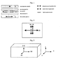
- FIG. 1 shows the fundamental structure of IPS-LCDs.
- an IPS-LCD comprises the first polarizer 1, the second polarizer 2 and the liquid crystal cell 3.
- the absorption axis 4 of the first polarizer and the absorption axis 5 of the second polarizer are arranged perpendicularly to each other, and the absorption axis 4 of the first polarizer and the optical axis of the liquid crystal cell are arranged parallel to each other.
- FIG. 2 shows the absorption axes 4, 5 of the two polarizers and the optical axis 6 of the liquid crystal cell.
- the liquid crystal display including the compensation films according to the present invention comprises the first polarizer 1, a horizontally aligned liquid crystal cell 3 having liquid crystals with positive dielectric anisotropy ( ⁇ > 0) or negative dielectric anisotropy ( ⁇ ⁇ 0) filled between two sheets of glass substrates, and the second polarizer 2, in which the optical axis 6 of the liquid crystals in the liquid crystal cell lies in a plane parallel to the polarizers.
- the absorption axis of the first polarizer and the absorption axis of the second polarizer are perpendicular to each other, and the optical axis 6 of the liquid crystals in the liquid crystal cell is parallel to the absorption axis 4 of the adjacent first polarizer.
- one of the first substrate 15 and the second substrate 16 has an active matrix drive electrode comprising an electrode pair, which is formed on a surface adjacent to the liquid crystal layer.
- the retardation value of the liquid crystal cell (IPS-LCD panel) in the inventive IPS-LCD preferably ranges from 200 nm to 350 nm at a wavelength of 550 nm.
- the retardation value of the IPS-LCD panel must be half of a wavelength of 589 nm (the brightest monochromatic light felt by people) such that the light linearly polarized to 90° through the first polarizer is linearly polarized to 0° through the liquid crystal layer upon the application of voltage to the IPS-LCD panel, thus becoming the bright state.
- the retardation value of the IPS-LCD panel may be slightly longer or shorter than the half-wavelength, depending on the wavelength dispersion characteristics of the used liquid crystals. For this reason, the retardation value is preferably about 295 nm which is the half-wavelength of 598-nm monochromatic light.
- the inventive LCDs include one where liquid crystals are either aligned in multi-domains or divided into multi-domains by applied voltage.
- IPS-LCD in-plane-switching
- Super-IPS super-in-plane-switching
- FFS fringe-field-switching
- the present invention is characterized by using the positive C-plate and the negative biaxial retardation film in combination for the viewing-angle compensation of IPS-LCDs. If the positive C-plate and the negative biaxial retardation film are used in combination for the viewing-angle compensation of IPS-LCDs, it will be possible to realize wide-viewing-angle characteristics.
- the total sum of the thickness-direction retardation values of the positive C-plate and the adjacent negative biaxial retardation film is positive value, and the in-plane retardation value of the biaxial retardation film functions as an A-plate.
- the refractive index of the retardation films used for the viewing-angle compensation of IPS-LCDs will now be described with reference to FIG. 3 .
- the refractive index in the x-axis direction may be referred to as n x 8
- the refractive index in the y-axis direction as n y 9
- the refractive index in the thickness direction i.e., the z-axis direction
- the characteristics of the retardation films will be determined.
- a film where the refractive indexes in the two-axis directions among the refractive indexes in the three-axis directions are different from each other is referred to as an uniaxial film.
- the uniaxial film can be defined as follows.
- the positive C-plate is a film whose in-plane retardation value is almost zero and thickness-direction retardation is positive value.
- the thickness-direction retardation value of the positive C-plate which is used for the viewing-angle compensation of IPS-LCDs preferably ranges from 50nm to 500 nm at a wavelength of 550 nm.
- a positive thickness-direction retardation value is required to minimize the light transmitted in the dark state of the polarizers.
- a negative biaxial retardation film is used, there will be no positive thickness-direction retardation value.
- the positive C-plate needs to be used either to reduce the negative thickness-direction retardation value or to make it positive.
- the range of thickness-direction retardation value allowing the viewing-angle compensation of the polarizers and the IPS-LCD panel is 50 nm to 500 nm, and this range is required either to reduce the negative thickness-direction retardation value or to make it positive.
- the wavelength dispersion characteristics of films may have normal wavelength dispersion, flat wavelength dispersion, or reverse wavelength dispersion.
- a film whose refractive indexes in the three-axis directions are different from each other is referred to as a biaxial retardation film which is defined as follows.
- the refractive index in the x-axis direction is referred to as n x 8
- the refractive index in the y-axis direction is referred to as n y 9
- the refractive index in the thickness direction is n z 10.
- a film with n x > n y > n z is referred to as a negative biaxial retardation film.
- R th, biaxial d ⁇ (n z - n y ) wherein d represents the thickness of the film.
- the negative biaxial retardation film preferably has an in-plane retardation value ranging from 20 nm to 200 nm at a wavelength of 550 nm, and a negative thickness-direction retardation value ranging from -50 nm to -300 nm at a wavelength of 550 nm.
- the wavelength dispersion characteristics of the film may have normal wavelength dispersion, flat wavelength dispersion and reverse wavelength dispersion.
- the structures of the viewing-angle compensation films including the positive C-plate and the negative biaxial retardation film are shown in shown in FIGS. 4, 5 , 6 and 7 .
- the optical axis of the liquid crystal molecules 7 in the liquid crystal cell 3 sandwiched between the two crossed polarizers is arranged parallel to the IPS-LCD panel substrate, and is aligned in the rubbing direction.
- An IPS-LCD where the absorption axis 4 of the first polarizer adjacent to a backlight is parallel to the rubbing direction 6 is referred to as an O-mode IPS-LCD, and an IPS-LCD where the absorption axis of the polarizer adjacent to the backlight is perpendicular to the rubbing direction 6 is referred to as an E-mode IPS-LCD.
- the first polarizer 1 adjacent to the backlight is referred to as a lower polarizer
- the second polarizer 2 arranged away from the backlight is referred to as an upper polarizer.
- Absorption axes of the two polarizers are so arranged as to be crossed with each other.
- the two kinds of the retardation films need to be placed between the IPS-LCD panel 3 and the polarizers.
- the slow axis or optical axis 13 of the retardation films may be arranged perpendicularly or in parallel to the absorption axis 5 of the polarizer adjacent thereto.
- the direction of the optical axis of the retardation films is determined depending on the arrangement order of the retardation films.
- the optical axis of the A-plate should be so arranged as to coincide with the transmission axis of the polarizer. If the positive C-plate is adjacent to the polarizer, the optical axis of the A-plate should be perpendicular with the absorption axis of the polarizer placed away from the A-plate, and if the A plate is adjacent to the polarizer, it should be perpendicular to the polarizer adjacent thereto.
- the first retardation film is referred to as the negative biaxial retardation film 12
- the second retardation film is referred to as the positive C-plate 11.
- the absolute value of the thickness-direction retardation of the second retardation film is preferably larger than that of the first retardation film as given in the following relation: R th > positive C - plate R biaxial
- the total sum of the thickness-direction retardation values of the compensation films is positive value in order to improve the viewing-angle characteristics of IPS-LCDs.
- the above condition means that the total sum of the thickness-direction retardation values of the compensation films should be positive value.
- a first embodiment of the present invention provides an IPS-LCD device, in which the negative biaxial retardation film 12 and the positive C-plate 11 are arranged between the liquid crystal cell 3 and the second polarizer 2, the positive C-plate is arranged between the negative biaxial retardation film 12 and the liquid crystal cell 3, and the optical axis 13 of the negative biaxial retardation film is perpendicular to the absorption axis 5 of the adjacent second polarizer 13.
- the minimization of light leakage by the crossed polarizers is possible only when the optical axis of the A-plate and the transmission axis of the adjacent polarizer coincide with each other. Since the absorption axis of the polarizers makes a right angle with the transmission axis, the optical axis of the negative biaxial retardation film and the absorption axis of the adjacent second polarizer should make a right angle with respect to each other.
- the positive C-plate preferably has a thickness-direction retardation value ranging from 50 nm to 500 nm at a wavelength of 550 nm.
- the thickness-direction retardation value of negative biaxial retardation films which can be fabricated at the present time ranges from -50 nm to -300 nm.
- the positive C-plate is needed for the total sum of the thickness-direction retardation values to have positive value, because it is preferred for the viewing-angle compensation of IPS-LCDs that the total sum of the thickness-direction retardation values ranges from +50 nm to +300 nm.
- the in-plane retardation value of the negative biaxial retardation film required for the viewing-angle compensation of IPS-LCDs is preferably less than 150 nm.
- the first structure of IPS-LCD shown in FIG. 4 which has the compensation films, will be described as follows.
- the negative biaxial retardation film and the positive C-plate are arranged between the second polarizer 2 and the liquid crystal cell 3 in such a way that the negative biaxial retardation film is adjacent to the second polarizer 2.
- the optical axis 13 of the negative biaxial retardation film is so arranged as to be perpendicular to the absorption axis 5 of the second polarizer.
- a backlight should be arranged adjacent to the first polarizer, and if the backlight is arranged adjacent to the second polarizer, the viewing-angle compensation characteristics will vary.
- the viewing-angle characteristics of the IPS-LCD are determined depending on how the internal protective films for the polarizers, and the retardation values of the positive C-plate and the negative biaxial retardation film, are designed.
- Table 1 above summarizes the results of simulation for viewing-angle characteristics according to the internal protective film for the first polarizer, the retardation value of the positive C-plate, the retardation value of the negative biaxial retardation film, and the internal protective film for the second polarizer. Since IPS-LCDs show low-contrast characteristics at an inclination angle of 70°, the minimum contrast ratio at an inclination angle of 70° is an index indicating the extent of an improvement in contrast characteristics. IPS-LCDs including general polarizers, to which the viewing-angle compensation films have not been applied, have a minimum contrast ratio of less than 10:1 at an inclination angle of 70°. Accordingly, it can be found that the structures given in Table 1 all have an improvement in contrast characteristics, and among these results, the structure showing the highest contrast ratio is a structure showing the most excellent contrast characteristic.
- a second embodiment of the present invention provides an IPS-LCD device, in which the negative biaxial retardation film 12 and the positive C-plate 11 are arranged between the liquid crystal cell 3 and the second polarizer 2, the negative biaxial retardation film is arranged between the positive C-plate and the liquid crystal cell, and the optical axis 13 of the negative biaxial retardation film is parallel to the absorption axis 5 of the second polarizer.
- the optical axis of the negative biaxial retardation film should be perpendicular to the absorption axis of the adjacent polarizer.
- the negative biaxial retardation film is influenced by the first polarizer.
- the optical axis of the negative biaxial retardation film should be perpendicular to the absorption axis of the first polarizer and coincided with the absorption axis of the second polarizer.
- the second structure of the IPS-LCD as shown in FIG. 5 which has the compensation films, will be described as follows.
- the negative biaxial retardation film and the positive C-plate are arranged between the second polarizer 2 and the IPS-liquid crystal cell 3 in such a manner that the positive C-plate is adjacent to the second polarizer 2.
- the optical axis 13 of the negative biaxial retardation film is arranged parallel to the absorption axis of the second polarizer. Simulations on this arrangement were performed while applying the actual design values of the retardation films, and the results are shown in Table 2 below.
- Table 2 above shows the results of simulation for contrast characteristics at an inclination angle of 70° according to the retardation values of the internal protective films for the polarizers, the retardation value of the positive C-plate, and the retardation value of the negative biaxial retardation film.
- IPS-LCDs show the minimum contrast ratio at an inclination angle of 70°
- IPS-LCDs having general polarizers, to which the compensation plates have not been applied show a contrast ratio of less than 10:1 at an inclination angle of 70°. Accordingly, an improvement in contrast characteristics at an inclination angle of 70°, as shown in Table 2, means an improvement in contrast characteristics in all the viewing-angle directions.
- a third embodiment of the present invention provides an IPS-LCD device, in which the negative biaxial retardation film 12 and the first positive C-plate 11 are arranged between the second polarizer 2 and the liquid crystal cell 3, the second positive C-plate 14 is arranged between the first polarizer 1 and the liquid crystal cell 3, the first positive C-plate 11 is arranged between the negative biaxial retardation film 12 and the liquid crystal cell 3, and the optical axis 13 of the negative biaxial retardation film is perpendicular to the absorption axis 5 of the adjacent second polarizer.
- the optical axis of the negative biaxial retardation film should coincide with the transmission axis of the adjacent polarizer. Since the transmission axis of the polarizer is perpendicular to the absorption axis thereof, the optical axis of the negative biaxial retardation film should be perpendicular to the absorption axis of the polarizer.
- the negative biaxial retardation film preferably has an in-plane retardation value ranging from 20 nm to 200 nm and a thickness-direction retardation value ranging from -50 nm to -300 nm.
- the total sum of the thickness-direction retardation values of the first and second positive C-plates preferably ranges from 50 nm to 500 nm.
- the total sum of the thickness-direction retardation values of the two positive C-plates should be larger than the thickness-direction retardation value of the negative biaxial retardation film.
- the third structure of the IPS-LCD as shown in FIG. 6 which has the compensation films, will be described as follows.
- the negative biaxial retardation film and the first positive C-plate 11 are arranged between the second polarizer 2 and the IPS-liquid crystal cell 3, and the negative biaxial retardation film 12 is arranged adjacent to the second polarizer 2.
- the optical axis 13 of the negative biaxial retardation film is arranged perpendicularly to the absorption axis 5 of the second polarizer.
- the second positive C-plate is arranged between the first polarizer 1 and the IPS-LCD panel 3.
- Table 3 above summarizes the results of simulation for the minimum contrast ratio at an inclination angle of 70° according to the retardation value of the internal protective film for the first polarizer, the retardation value of the internal protective films for the second polarizer, the retardation value of the first positive C-plate, the retardation value of the second positive C-plate, and the retardation value of the negative biaxial retardation film.
- a fourth embodiment of the present invention provides an IPS-LCD device, in which the negative biaxial retardation film 12 and the first positive C-plate 11 are arranged between the second polarizer 2 and the liquid crystal cell 3, the second positive C-plate 14 is arranged between the first polarizer 1 and the liquid crystal cell 3, the first positive C-plate 11 is arranged between the negative biaxial retardation film 12 and the second polarizer 2, and the optical axis 13 of the negative biaxial retardation film is parallel to the absorption axis 5 of the second polarizer.
- the optical axis of the negative biaxial retardation film should be perpendicular to the absorption axis of the adjacent polarizer.
- the negative biaxial retardation film acts with the first polarizer, and it is needed that the optical axis of the negative biaxial retardation film coincides with the transmission axis of the first polarizer.
- the optical axis of the negative biaxial retardation film should coincide with the absorption axis of the second polarizer.
- the fourth structure of the IPS-LCD as shown in FIG. 7 which has the compensation films, will be described as follows.
- the negative biaxial retardation film and the first positive C-plate are arranged between the second polarizer 2 and the IPS-liquid crystal cell 3, and the first positive C-plate is arranged adjacent to the second polarizer 2.
- the optical axis 13 of the negative biaxial retardation film is arranged parallel to the absorption axis 5 of the second polarizer.
- the second positive C-plate is arranged between the first polarizer 1 and the IPS-liquid crystal cell 3.
- the IPS-LCDs shown in FIGS. 4 to 7 comprise the two crossed polarizers 1, 2, the liquid cell 3, and at least one positive C-plate 11 and at least one negative biaxial retardation film 12 arranged between the second polarizer 2 and the liquid crystal cell 3.
- the diagonal direction refers to the 45° direction with respect to the absorption axes of the polarizers, and is a direction in which the viewing-angle characteristics of IPS-LCDs in the state of the crossed polarizers are most poor.
- the two kinds of the retardation films are applied as viewing-angle compensation films for IPS-LCDs according to the present invention, the viewing-angle characteristics in the diagonal direction will be improved.
- the polarizers may have internal and external protective films.
- the polarizers may comprise, as an internal protective film, triacetate cellulose (TAC) with thickness-direction retardation value, polynorbornene(PNB) or unstreched cyclo-olefin (COP) with no thickness-direction retardation value.
- TAC triacetate cellulose
- PPB polynorbornene
- COP unstreched cyclo-olefin
- the viewing-angle compensation characteristics of IPS-LCDS are influenced by the protective film which is used for the protection of the polarizing element. If a protective film having thickness-direction retardation value, such as a TAC film, there will be a problem in that the viewing-angle compensation characteristics are deteriorated. If an isotropic film, such as an unstreched cyclo-olefin (COP), is used as a protective film for the polarizers, excellent viewing-angle compensation characteristics can be secured.
- COP unstreched cyclo-olefin
- a film having a zero or negative thickness-direction retardation value is preferably used as the internal protective film for the first polarizer, the second polarizer or both the two polarizers. This is because the positive C-plate adjacent to the polarizer offsets the retardation value generated by the internal protective film for the polarizer.
- the internal protective films for the first polarizer 1 and the second polarizer 2 is preferably made of a material selected from the group consisting of unstretched COP, 40- ⁇ m TAC, 80 ⁇ m-TAC, and PNB.
- Examples of a film which can be used as the negative biaxial retardation film 12 include uniaxially stretched TAC, uniaxially stretched polynorborene (PNB), and biaxially stretched polycarbonate films.
- the positive C-plate 11 as the second retardation film may be made of a polymer material or an UV curable liquid crystal film, and examples thereof include a homebtropically aligned liquid crystal film, a biaxially stretched polycarbonate film, and the like.
- the negative biaxial retardation film 12 can serve as an internal protective film for the polarizers. Since the purpose of the internal protective film for the polarizers is to protect the polarizing element, any transparent material having a function to protect the polarizers may be used as the protective material. Since the negative biaxial retardation film is made of a transparent material having a function to protect the polarizers, it can serve as a retardation film having a function to protect the polarizers.
- the positive C-plate 11 can serve as a protective film for the polarizers. Since the positive C-plate is made of a transparent material having a function to protect the polarizers, it can serve as a retardation film having a function to protect the polarizers.
- TAC A material which is most widely used as a protective film for general polarizers is TAC. Since TAC has negative thickness-direction retardation value, the direct use of the negative biaxial retardation film as a protective film for the polarizers has the effect of reducing the negative thickness-direction retardation value. This allows viewing-angle compensation with a small thickness-direction retardation value of the positive C-plate (see Table 1).
- a positive C-plate having a large retardation value should be used to make the total sum of thickness-direction retardation values larger than zero. If the thickness-direction retardation value of the internal protective film for the polarizers is zero or negative, a positive C-plate having a small retardation value may be used to improve viewing-angle characteristics.
- the IPS-LCD shown in Table 1 above comprises the IPS liquid crystal cell which has a cell gap of 2.9 ⁇ m and is filled with liquid crystal molecules having a pretilt angle of 3°, a dielectric anisotropy ( ⁇ ) of +7 and a birefringence ( ⁇ n) of 0.1.
- the negative biaxial retardation film 12 is made of a stretched TAC film and has an in-plane retardation value (R in ) of 110 nm and a thickness-direction retardation value (R th ) of -48 nm.
- the positive C-plate 11 is an UV cured, homeotropically aligned liquid crystal film and has a retardation value (R th ) of 133 nm.
- Two sheets of the polarizers comprise an internal protective film of COP having a retardation value of almost zero.
- the result of simulation for the minimum contrast ratio at an inclination angle of 70° with respect to all azimuthal angles in the case of the application of such viewing-angle compensation films is 150:1.
- the IPS-LCD shown in Table 1 above comprises the IPS liquid crystal cell which has a cell gap of 2.9 ⁇ m and is filled with liquid crystal molecules having a pretilt angle of 3°, a dielectric anisotropy ( ⁇ ) of +7 and a birefringence ( ⁇ n) of 0.1.
- the negative biaxial retardation film 12 is made of a stretched TAC film and has an in-plane retardation value (R in ) of 66 nm and a thickness-direction retardation value (R th ) of -128 nm.
- the positive C-plate 11 is an UV cured, homeotropically aligned liquid crystal film and has a retardation value (R th ) of 120 nm.
- An internal protective film for the first polarizer 1 is made of TAC and has a thickness-direction retardation value (R th ) of -65 nm.
- An internal protective film for the second polarizer 2 is a COP film having a retardation value of almost zero.
- the result of simulation for the minimum contrast ratio at an inclination angle of 70° with respect to all azimuthal angles in the case of the application of such viewing-angle compensation films is 30:1.
- the IPS-LCD shown in Table 1 above comprises the IPS liquid crystal cell which has a cell gap of 2.9 ⁇ m and is filled with liquid crystal molecules having a pretilt angle of 3°, a dielectric anisotropy ( ⁇ ) of +7 and a birefringence ( ⁇ n) of 0.1.
- the negative biaxial retardation film 12 is made of a stretched TAC film and has an in-plane retardation value (R in ) of 110 nm and a thickness-direction retardation value (R th ) of -48 nm.
- the positive C-plate 11 is an UV cured, homeotropically aligned liquid crystal film and has a retardation value (R th ) of 133 nm.
- An internal protective film for the first polarizer 1 is made of COP, and an internal protective film for the second polarizer 2 is a stretched TAC film.
- the result of simulation for the minimum contrast ratio at an inclination angle of 70° with respect to all azimuthal angles in the case of the application of such viewing-angle compensation films is 150:1.
- the IPS-LCD shown in Table 2 above comprises the IPS liquid crystal cell which has a cell gap of 2.9 ⁇ m and is filled with liquid crystal molecules having a pretilt angle of 3°, a dielectric anisotropy ( ⁇ ) of +7 and a birefringence ( ⁇ n) of 0.1.
- the negative biaxial retardation film 12 is made of a stretched TAC film and has an in-plane retardation value (R in ) of 77 nm and a thickness-direction retardation value (R th ) of -165 nm.
- the positive C-plate 11 is an UV cured, homeotropically aligned liquid crystal film and has a retardation value (R th ) of 305 nm.
- An internal protective film for the first polarizer 1 is made of COP
- an internal protective film for the second polarizer 2 is made of 80- ⁇ m TAC and has a thickness-direction retardation value (R th ) of -65 nm.
- the result of simulation for the minimum contrast ratio at an inclination angle of 70° with respect to all azimuthal angles in the case of the application of such viewing-angle compensation films is 95:1.
- the IPS-LCD shown in Table 2 above comprises the IPS liquid crystal cell which has a cell gap of 2.9 ⁇ m and is filled with liquid crystal molecules having a pretilt angle of 3°, a dielectric anisotropy ( ⁇ ) of +7 and a birefringence ( ⁇ n) of 0.1.
- the negative biaxial retardation film 12 is made of a stretched TAC film and has an in-plane retardation value (R in ) of 77 nm and a thickness-direction retardation value (R th ) of -165 nm.
- the first positive C-plate 11 is an UV cured, homeotropically aligned liquid crystal film and has a retardation value (R th ) of 420 nm.
- An internal protective film for the first polarizer 1 is made of COP
- an internal protective film for the second polarizer 2 is a PNB film having a negative thickness-direction retardation value (R th ) of -160 nm.
- R th thickness-direction retardation value
- the IPS-LCD shown in Table 2 above comprises the IPS liquid crystal cell which has a cell gap of 2.9 ⁇ m and is filled with liquid crystal molecules having a pretilt angle of 3°, a dielectric anisotropy ( ⁇ ) of +7 and a birefringence ( ⁇ n) of 0.1.
- the negative biaxial retardation film 12 is made of a stretched TAC film and has an in-plane retardation value (R in ) of 74 nm and a thickness-direction retardation value (R th ) of -162 nm.
- the positive C-plate 11 is an UV cured, homeotropically aligned liquid crystal film and has a retardation value (R th ) of 230 nm.
- An internal protective film for the first polarizer 1 is made of COP
- an internal protective film for the second polarizer 2 is made of COP.
- the IPS-LCD shown in Table 3 above comprises the IPS liquid crystal cell which has a cell gap of 2.9 ⁇ m and is filled with liquid crystal molecules having a pretilt angle of 3°, a dielectric anisotropy ( ⁇ ) of +7 and a birefringence ( ⁇ n) of 0.1.
- the negative biaxial retardation film 12 is made of a stretched TAC film and has an in-plane retardation value (R in ) of 92 nm and a thickness-direction retardation value (R th ) of -102 nm.
- the second positive C-plate 11 is an UV cured, homeotropically aligned liquid crystal film and has a retardation value (R th ) of 110 nm.
- the first positive C-plate 12 is an UV cured, homeotropically aligned liquid crystal film and has a retardation value (R th ) of 215 nm.
- An internal protective film for the first polarizer 1 is made of 80- ⁇ m TCA having a thickness-direction retardation value (R th ) of -65 nm.
- An internal protective film for the second polarizer 2 is made of COP. The result of simulation for the minimum contrast ratio at an inclination angle of 70° with respect to all azimuthal angles in the case of the application of such viewing-angle compensation films is 136:1.
- the IPS-LCD shown in Table 3 above comprises the IPS liquid crystal cell which has a cell gap of 2.9 ⁇ m and is filled with liquid crystal molecules having a pretilt angle of 3°, a dielectric anisotropy ( ⁇ ) of +7 and a birefringence ( ⁇ n) of 0.1.
- the negative biaxial retardation film 12 is made of a stretched TAC film and has an in-plane retardation value (R in ) of 92 nm and a thickness-direction retardation value (R th ) of -102 nm.
- the second positive C-plate 11 is an UV cured, homeotropically aligned liquid crystal film and has a retardation value (R th ) of 220 nm.
- the first positive C-plate 14 is an UV cured, homeotropically aligned liquid crystal film and has a retardation value (R th ) of 215 nm.
- An internal protective film for the first polarizer 1 is made of PNB and has a thickness-direction retardation value (R th ) of - 160 nm.
- An internal protective film for the second polarizer 2 is made of COP. The result of simulation for the minimum contrast ratio at an inclination angle of 70° with respect to all azimuthal angles in the case of the application of such viewing-angle compensation films is 125:1.
- the IPS-LCD shown in Table 4 above comprises the IPS liquid crystal cell which has a cell gap of 2.9 ⁇ m and is filled with liquid crystal molecules having a pretilt angle of 3°, a dielectric anisotropy ( ⁇ ) of +7 and a birefringence ( ⁇ n) of 0.1.
- the negative biaxial retardation film 12 is made of a stretched TAC film and has an in-plane retardation value (R in ) of 88 nm and a thickness-direction retardation value (R th ) of -65 nm.
- the second positive C-plate 11 is an UV cured, homeotropically aligned liquid crystal film and has a retardation value (R th ) of 110 nm.
- the first positive C-plate 14 is an UV cured, homeotropically aligned liquid crystal film and has a retardation value (R th ) of 163 nm.
- An internal protective film for the first polarizer 1 is made of 80- ⁇ m TAC and has a thickness-direction retardation value (R th ) of -65 nm.
- An internal protective film for the second polarizer 2 is made of COP. The result of simulation for the minimum contrast ratio at an inclination angle of 70° with respect to all azimuthal angles in the case of the application of such viewing-angle compensation films is 150:1.
- the IPS-LCD shown in Table 4 above comprises the IPS liquid crystal cell which has a cell gap of 2.9 ⁇ m and is filled with liquid crystal molecules having a pretilt angle of 3°, a dielectric anisotropy ( ⁇ ) of +7 and a birefringence ( ⁇ n) of 0.1.
- the negative biaxial retardation film 12 is made of a stretched TAC film and has an in-plane retardation value (R in ) of 88 nm and a thickness-direction retardation value (R th ) of -65 nm.
- the second positive C-plate 11 is an UV cured, homeotropically aligned liquid crystal film and has a retardation value (R th ) of 220 nm.
- the first positive C-plate 14 is an UV cured, homeotropically aligned liquid crystal film and has a retardation value (R th ) of 163 nm.
- An internal protective film for the first polarizer 1 is made of PNB and has a thickness-direction retardation value (R th ) of - 160 nm.
- An internal protective film for the second polarizer 2 is made of COP. The result of simulation for the minimum contrast ratio at an inclination angle of 70° with respect to all azimuthal angles in the case of the application of such viewing-angle compensation films is 140:1.
- the use of the negative biaxial retardation film and the positive C-plate allows improvements in the contrast characteristics at the front side and inclination angle of in-plane switching liquid crystal displays. Also, it allows the minimization of color shift with viewing angle in the dark state.
Landscapes
- Physics & Mathematics (AREA)
- Chemical & Material Sciences (AREA)
- Nonlinear Science (AREA)
- Optics & Photonics (AREA)
- General Physics & Mathematics (AREA)
- Crystallography & Structural Chemistry (AREA)
- Mathematical Physics (AREA)
- Materials Engineering (AREA)
- Organic Chemistry (AREA)
- Geometry (AREA)
- Metallurgy (AREA)
- Engineering & Computer Science (AREA)
- Chemical Kinetics & Catalysis (AREA)
- Electrochemistry (AREA)
- Mechanical Engineering (AREA)
- General Chemical & Material Sciences (AREA)
- Liquid Crystal (AREA)
- Polarising Elements (AREA)
Abstract
Description
- The present invention relates to liquid crystal displays (LCDs), and more particularly, to an in-plane switching liquid crystal display (IPS-LCD) filled with liquid crystals having positive dielectric anisotropy (Δε > 0) or negative dielectric anisotropy (Δε < 0), the display comprising a negative biaxial retardation film and a positive C-plate, as viewing-angle compensation films for improving the viewing-angle characteristics of the display.
- IPS-LCDs are disclosed in
US Patent No. 3,807,831 , but this patent does not disclose the use of viewing-angle compensation films. IPS-LCDs including no viewing-angle compensation films have a disadvantage in that they have a low contrast ratio due to a relatively large light leakage in the dark state at inclination angle. -
-
FIG. 1 shows the fundamental structure of IPS-LCDs. -
FIG. 2 shows the arrangement of the absorption axes of polarizers and the optical axis of liquid crystals of an IPS-LCD panel in the fundamental structure ofFIG. 1 . -
FIG. 3 shows the refractive index of a retardation film. -
FIG. 4 shows the first structure of the inventive IPS-LCD comprising viewing-angle compensation films. -
FIG. 5 shows the second structure of the inventive IPS-LCD comprising viewing-angle compensation films. -
FIG. 6 shows the third structure of the inventive IPS-LCD comprising viewing-angle compensation films. -
FIG. 7 shows the fourth structure of the inventive IPS-LCD structure comprising viewing-angle compensation films. - It is an object of the present invention to provide an IPS-LCD, which has high-contrast characteristics and low color shift at the front side and inclination angle by minimizing light leakage in the dark state at inclination angle.
- The causes of reducing the viewing-angle characteristics of IPS-LCDs are broadly classified into two classes: The first is the viewing-angle dependence of a perpendicularity between the absorption axes of two polarizers, and the second is the viewing-angle dependence of birefringent characteristics of an IPS-LCD panel.
- The present inventors have recognized that a negative biaxial retardation film and a positive C-plate are required to compensate for these two causes of reducing viewing angle, and designed viewing-angle compensation films with these two kinds of the retardation compensation films in order to realize wide-viewing-angle characteristics.
- Moreover, the present inventors have found that, for suitable compensation for viewing angle, the optical axis direction of the negative biaxial retardation film should be suitably determined depending on the arrangement order of the negative biaxial retardation film and the positive C-plate between polarizers and a liquid crystal cell (IPS-LCD panel). On the basis of this finding, the present invention has been completed.
- The present invention provides an IPS-LCD which overcame the viewing-angle problem using the negative biaxial retardation film and the positive C-plate.
- More specifically, the present invention provides an in-plane switching liquid crystal display (IPS-LCD) comprising a first polarizer, a horizontally aligned liquid crystal cell filled with liquid crystals having positive dielectric anisotropy (Δε>0) or negative dielectric anisotropy (Δε<0), and a second polarizer, the optical axis of the liquid crystals in the liquid crystal cell lying in a plane parallel to the polarizers, in which the absorption axis of the first polarizer and the absorption axis of the second polarizer are perpendicular to each other, the optical axis of the liquid crystals in the liquid crystal cell is parallel to the absorption axis of the adjacent first polarizer, for viewing-angle compensation at least one negative biaxial retardation film (nx > ny > nz) and at least one positive C-plate (nx = ny < nz) are arranged between the polarizers and the liquid crystal cell, in which the optical axis of the negative biaxial retardation film is arranged perpendicularly to (a) the absorption axis of the polarizer just adjacent to the negative biaxial retardation film, or (b) the absorption axis of the polarizer adjacent to the liquid crystal cell when the negative biaxial retardation film is adjacent to the liquid crystal cell.
- Contrast ratio value is the index of image sharpness, and the higher the contrast ratio value, the more sharp images can be realized. IPS-LCDs have the most inferior contrast characteristic at an inclination angle of 70°, and an improvement in the contrast characteristic at an inclination angle of 70° means an improvement in the contrast characteristics at all viewing-angles. The minimum contrast ratio at an inclination angle of 70° is less than 10:1 in the use of only polarizers, and can reach at least 20:1 when the positive C-plate and the negative biaxial retardation film are used according to the present invention. The minimum contrast ratio at an inclination angle of 70° is preferably more than 20:1.
- Hereinafter, the present invention will be described in detail.
-
FIG. 1 shows the fundamental structure of IPS-LCDs. - As shown in
FIG. 1 , an IPS-LCD comprises thefirst polarizer 1, thesecond polarizer 2 and theliquid crystal cell 3. Theabsorption axis 4 of the first polarizer and theabsorption axis 5 of the second polarizer are arranged perpendicularly to each other, and theabsorption axis 4 of the first polarizer and the optical axis of the liquid crystal cell are arranged parallel to each other.FIG. 2 shows theabsorption axes optical axis 6 of the liquid crystal cell. - The liquid crystal display including the compensation films according to the present invention comprises the
first polarizer 1, a horizontally alignedliquid crystal cell 3 having liquid crystals with positive dielectric anisotropy (Δε > 0) or negative dielectric anisotropy (Δε < 0) filled between two sheets of glass substrates, and thesecond polarizer 2, in which theoptical axis 6 of the liquid crystals in the liquid crystal cell lies in a plane parallel to the polarizers. In this IPS-LCD device, the absorption axis of the first polarizer and the absorption axis of the second polarizer are perpendicular to each other, and theoptical axis 6 of the liquid crystals in the liquid crystal cell is parallel to theabsorption axis 4 of the adjacent first polarizer. Also, one of thefirst substrate 15 and thesecond substrate 16 has an active matrix drive electrode comprising an electrode pair, which is formed on a surface adjacent to the liquid crystal layer. - The retardation value of the liquid crystal cell (IPS-LCD panel) in the inventive IPS-LCD preferably ranges from 200 nm to 350 nm at a wavelength of 550 nm.
- This is because the retardation value of the IPS-LCD panel must be half of a wavelength of 589 nm (the brightest monochromatic light felt by people) such that the light linearly polarized to 90° through the first polarizer is linearly polarized to 0° through the liquid crystal layer upon the application of voltage to the IPS-LCD panel, thus becoming the bright state. Also, to make the light white, the retardation value of the IPS-LCD panel may be slightly longer or shorter than the half-wavelength, depending on the wavelength dispersion characteristics of the used liquid crystals. For this reason, the retardation value is preferably about 295 nm which is the half-wavelength of 598-nm monochromatic light.
- The inventive LCDs include one where liquid crystals are either aligned in multi-domains or divided into multi-domains by applied voltage.
- LCDs are classified according to the mode of active matrix derive electrodes into in-plane-switching (IPS), super-in-plane-switching (Super-IPS), and fringe-field-switching (FFS) LCDs. In the specification, if the term "IPS-LCD" is used, it will be construed to include super-IPS, FFS (fringe field switching), reverse TN IPS LCDs, etc.
- The present invention is characterized by using the positive C-plate and the negative biaxial retardation film in combination for the viewing-angle compensation of IPS-LCDs. If the positive C-plate and the negative biaxial retardation film are used in combination for the viewing-angle compensation of IPS-LCDs, it will be possible to realize wide-viewing-angle characteristics.
- The total sum of the thickness-direction retardation values of the positive C-plate and the adjacent negative biaxial retardation film is positive value, and the in-plane retardation value of the biaxial retardation film functions as an A-plate. Thus, light leakage generated in the polarizers and the IPS-LCD panel can be minimized.
- The refractive index of the retardation films used for the viewing-angle compensation of IPS-LCDs will now be described with reference to
FIG. 3 . As shown inFIG. 3 , among in-plane refractive indexes, the refractive index in the x-axis direction may be referred to asn x 8, the refractive index in the y-axis direction asn y 9, and the refractive index in the thickness direction (i.e., the z-axis direction) asn z 10. Depending on the magnitudes of the refractive indexes, the characteristics of the retardation films will be determined. - A film where the refractive indexes in the two-axis directions among the refractive indexes in the three-axis directions are different from each other is referred to as an uniaxial film. The uniaxial film can be defined as follows.
- (1) A film with nx > ny = nz is referred to as a positive A-plate, the in-plane retardation value of which is defined using the difference between two refractive indexes lying in a plane, and the thickness of the film as given in the
following equation 1.
- (2) A film with nx = ny < nz is referred to as a positive C-plate, the thickness-direction retardation value of which is defined using the difference between the in-plane refractive index and the thickness-direction refractive index, and the thickness of the film as given in the following equation.

- The positive C-plate is a film whose in-plane retardation value is almost zero and thickness-direction retardation is positive value.
- The thickness-direction retardation value of the positive C-plate which is used for the viewing-angle compensation of IPS-LCDs preferably ranges from 50nm to 500 nm at a wavelength of 550 nm.
- A positive thickness-direction retardation value is required to minimize the light transmitted in the dark state of the polarizers. However, if a negative biaxial retardation film is used, there will be no positive thickness-direction retardation value. Thus, the positive C-plate needs to be used either to reduce the negative thickness-direction retardation value or to make it positive. The range of thickness-direction retardation value allowing the viewing-angle compensation of the polarizers and the IPS-LCD panel is 50 nm to 500 nm, and this range is required either to reduce the negative thickness-direction retardation value or to make it positive.
- The wavelength dispersion characteristics of films may have normal wavelength dispersion, flat wavelength dispersion, or reverse wavelength dispersion.
- A film whose refractive indexes in the three-axis directions are different from each other is referred to as a biaxial retardation film which is defined as follows.
- Of in-plane refractive indexes, the refractive index in the x-axis direction is referred to as
n x 8, the refractive index in the y-axis direction asn y 9, and the refractive index in the thickness direction asn z 10. A film with nx > ny > nz is referred to as a negative biaxial retardation film. The negative biaxial retardation film has both in-plane retardation value (Rin, biaxial) and thickness-direction retardation value (Rth, biaxial), which are defined as follows:
- Rth, biaxial = d × (nz - ny) wherein d represents the thickness of the film.
- For the viewing-angle compensation of IPS-LCDs, the negative biaxial retardation film preferably has an in-plane retardation value ranging from 20 nm to 200 nm at a wavelength of 550 nm, and a negative thickness-direction retardation value ranging from -50 nm to -300 nm at a wavelength of 550 nm.
- The wavelength dispersion characteristics of the film may have normal wavelength dispersion, flat wavelength dispersion and reverse wavelength dispersion.
- The structures of the viewing-angle compensation films including the positive C-plate and the negative biaxial retardation film are shown in shown in
FIGS. 4, 5 ,6 and 7 . - The optical axis of the
liquid crystal molecules 7 in theliquid crystal cell 3 sandwiched between the two crossed polarizers is arranged parallel to the IPS-LCD panel substrate, and is aligned in the rubbing direction. An IPS-LCD where theabsorption axis 4 of the first polarizer adjacent to a backlight is parallel to the rubbingdirection 6 is referred to as an O-mode IPS-LCD, and an IPS-LCD where the absorption axis of the polarizer adjacent to the backlight is perpendicular to the rubbingdirection 6 is referred to as an E-mode IPS-LCD. Thefirst polarizer 1 adjacent to the backlight is referred to as a lower polarizer, and thesecond polarizer 2 arranged away from the backlight is referred to as an upper polarizer. Absorption axes of the two polarizers are so arranged as to be crossed with each other. - In order to function to compensate for viewing angle, the two kinds of the retardation films need to be placed between the IPS-
LCD panel 3 and the polarizers. - The slow axis or
optical axis 13 of the retardation films may be arranged perpendicularly or in parallel to theabsorption axis 5 of the polarizer adjacent thereto. The direction of the optical axis of the retardation films is determined depending on the arrangement order of the retardation films. - In order to use the A-plate for the viewing-angle compensation of the polarizers, the optical axis of the A-plate should be so arranged as to coincide with the transmission axis of the polarizer. If the positive C-plate is adjacent to the polarizer, the optical axis of the A-plate should be perpendicular with the absorption axis of the polarizer placed away from the A-plate, and if the A plate is adjacent to the polarizer, it should be perpendicular to the polarizer adjacent thereto.
- Meanwhile, among the two kinds of the retardation films which are used for the viewing-angle compensation of IPS-LCDs, the first retardation film is referred to as the negative
biaxial retardation film 12, and the second retardation film is referred to as the positive C-plate 11. When the two kinds of the retardation films are stacked on each other, the absolute value of the thickness-direction retardation of the second retardation film is preferably larger than that of the first retardation film as given in the following relation:
- This is because it is preferred that the total sum of the thickness-direction retardation values of the compensation films is positive value in order to improve the viewing-angle characteristics of IPS-LCDs. The above condition means that the total sum of the thickness-direction retardation values of the compensation films should be positive value.
- A first embodiment of the present invention provides an IPS-LCD device, in which the negative
biaxial retardation film 12 and the positive C-plate 11 are arranged between theliquid crystal cell 3 and thesecond polarizer 2, the positive C-plate is arranged between the negativebiaxial retardation film 12 and theliquid crystal cell 3, and theoptical axis 13 of the negative biaxial retardation film is perpendicular to theabsorption axis 5 of the adjacentsecond polarizer 13. - The minimization of light leakage by the crossed polarizers is possible only when the optical axis of the A-plate and the transmission axis of the adjacent polarizer coincide with each other. Since the absorption axis of the polarizers makes a right angle with the transmission axis, the optical axis of the negative biaxial retardation film and the absorption axis of the adjacent second polarizer should make a right angle with respect to each other.
- In this embodiment, the positive C-plate preferably has a thickness-direction retardation value ranging from 50 nm to 500 nm at a wavelength of 550 nm.
- The thickness-direction retardation value of negative biaxial retardation films which can be fabricated at the present time ranges from -50 nm to -300 nm. Thus, the positive C-plate is needed for the total sum of the thickness-direction retardation values to have positive value, because it is preferred for the viewing-angle compensation of IPS-LCDs that the total sum of the thickness-direction retardation values ranges from +50 nm to +300 nm.
- Moreover, the in-plane retardation value of the negative biaxial retardation film required for the viewing-angle compensation of IPS-LCDs is preferably less than 150 nm.
- The first structure of IPS-LCD shown in
FIG. 4 , which has the compensation films, will be described as follows. - As shown in
FIG. 4 , the negative biaxial retardation film and the positive C-plate are arranged between thesecond polarizer 2 and theliquid crystal cell 3 in such a way that the negative biaxial retardation film is adjacent to thesecond polarizer 2. Theoptical axis 13 of the negative biaxial retardation film is so arranged as to be perpendicular to theabsorption axis 5 of the second polarizer. - A backlight should be arranged adjacent to the first polarizer, and if the backlight is arranged adjacent to the second polarizer, the viewing-angle compensation characteristics will vary.
- Simulations on this arrangement were performed while applying the actual design values of retardation films, and the results are shown in Table 1 below.
(Table 1) Internal protective film for first polarizer IPS-LCD panel Retardation value of positive C-plate Negative biaxial film Internal protective film of second polarizer Minimum contrast ratio at inclination angle of 70° Rin (nm) Rth (nm) COP 290 nm 300 67 -226 COP 65 249 69 -178 88 200 75 -145 107 133 110 -48 150 108 139 -8 143 80-µm TAC 315 40 -320 COP 25 160 60 -160 27 120 66 -128 30 COP 133 110 -48 TAC 150 COP 153 66 -33 80 µm TAC 125 COP 226 42 -15 PNB 75 Rth=160nm - The viewing-angle characteristics of the IPS-LCD are determined depending on how the internal protective films for the polarizers, and the retardation values of the positive C-plate and the negative biaxial retardation film, are designed.
- Table 1 above summarizes the results of simulation for viewing-angle characteristics according to the internal protective film for the first polarizer, the retardation value of the positive C-plate, the retardation value of the negative biaxial retardation film, and the internal protective film for the second polarizer. Since IPS-LCDs show low-contrast characteristics at an inclination angle of 70°, the minimum contrast ratio at an inclination angle of 70° is an index indicating the extent of an improvement in contrast characteristics. IPS-LCDs including general polarizers, to which the viewing-angle compensation films have not been applied, have a minimum contrast ratio of less than 10:1 at an inclination angle of 70°. Accordingly, it can be found that the structures given in Table 1 all have an improvement in contrast characteristics, and among these results, the structure showing the highest contrast ratio is a structure showing the most excellent contrast characteristic.
- A second embodiment of the present invention provides an IPS-LCD device, in which the negative
biaxial retardation film 12 and the positive C-plate 11 are arranged between theliquid crystal cell 3 and thesecond polarizer 2, the negative biaxial retardation film is arranged between the positive C-plate and the liquid crystal cell, and theoptical axis 13 of the negative biaxial retardation film is parallel to theabsorption axis 5 of the second polarizer. - For the viewing-angle compensation of IPS-LCDs, the optical axis of the negative biaxial retardation film should be perpendicular to the absorption axis of the adjacent polarizer. However, due to the positive C-plate next to the second polarizer, the negative biaxial retardation film is influenced by the first polarizer.
- Accordingly, the optical axis of the negative biaxial retardation film should be perpendicular to the absorption axis of the first polarizer and coincided with the absorption axis of the second polarizer.
- The second structure of the IPS-LCD as shown in
FIG. 5 , which has the compensation films, will be described as follows. - As shown in
FIG. 5 , the negative biaxial retardation film and the positive C-plate are arranged between thesecond polarizer 2 and the IPS-liquid crystal cell 3 in such a manner that the positive C-plate is adjacent to thesecond polarizer 2. Theoptical axis 13 of the negative biaxial retardation film is arranged parallel to the absorption axis of the second polarizer. Simulations on this arrangement were performed while applying the actual design values of the retardation films, and the results are shown in Table 2 below.(Table 2) Internal protective film for first polarizer IPS-LCD panel Negative biaxial film Retardation value of positive C-plate Internal protective film for second polarizer Minimum contrast ratio at inclination angle of 70° Rin (nm) Rth (nm) COP 290 nm 77 -165 305 80 µm TAC 95 COP 77 -165 420 PNB 86 Rth =160 nm 80-µmTAC 90 -162 390 PNB 25 Rth = 160nm COP 74 -162 230 COP 100 - Table 2 above shows the results of simulation for contrast characteristics at an inclination angle of 70° according to the retardation values of the internal protective films for the polarizers, the retardation value of the positive C-plate, and the retardation value of the negative biaxial retardation film.
- IPS-LCDs show the minimum contrast ratio at an inclination angle of 70°, and IPS-LCDs having general polarizers, to which the compensation plates have not been applied, show a contrast ratio of less than 10:1 at an inclination angle of 70°. Accordingly, an improvement in contrast characteristics at an inclination angle of 70°, as shown in Table 2, means an improvement in contrast characteristics in all the viewing-angle directions.
- A third embodiment of the present invention provides an IPS-LCD device, in which the negative
biaxial retardation film 12 and the first positive C-plate 11 are arranged between thesecond polarizer 2 and theliquid crystal cell 3, the second positive C-plate 14 is arranged between thefirst polarizer 1 and theliquid crystal cell 3, the first positive C-plate 11 is arranged between the negativebiaxial retardation film 12 and theliquid crystal cell 3, and theoptical axis 13 of the negative biaxial retardation film is perpendicular to theabsorption axis 5 of the adjacent second polarizer. - For the viewing-angle compensation of IPS-LCDs, the optical axis of the negative biaxial retardation film should coincide with the transmission axis of the adjacent polarizer. Since the transmission axis of the polarizer is perpendicular to the absorption axis thereof, the optical axis of the negative biaxial retardation film should be perpendicular to the absorption axis of the polarizer.
- In this embodiment, the negative biaxial retardation film preferably has an in-plane retardation value ranging from 20 nm to 200 nm and a thickness-direction retardation value ranging from -50 nm to -300 nm. The total sum of the thickness-direction retardation values of the first and second positive C-plates preferably ranges from 50 nm to 500 nm.
- Furthermore, the total sum of the thickness-direction retardation values of the two positive C-plates should be larger than the thickness-direction retardation value of the negative biaxial retardation film.
- The third structure of the IPS-LCD as shown in
FIG. 6 , which has the compensation films, will be described as follows. - As shown in
FIG. 6 , the negative biaxial retardation film and the first positive C-plate 11 are arranged between thesecond polarizer 2 and the IPS-liquid crystal cell 3, and the negativebiaxial retardation film 12 is arranged adjacent to thesecond polarizer 2. Theoptical axis 13 of the negative biaxial retardation film is arranged perpendicularly to theabsorption axis 5 of the second polarizer. The second positive C-plate is arranged between thefirst polarizer 1 and the IPS-LCD panel 3. - Simulations on this arrangement were performed while applying the actual design values of the retardation films, and the results are shown in Table 3 below.
(Table 3) Internal protective film of first polarizer Retardation value of second positive C-plate IPS-LCD panel Retardation value of first positive C-plate Negative biaxial film Internal protective film of second polarizer Minimum contrast ratio at inclination angle OF 70° Rin (nm) Rth (nm) 80-µm TAG 145 290 nm 272 93 -128 - 94 80-µm TAG 110 215 92 -102 COP 136 80-µm TAG 76 235 77 -160 - 100 PNB 220 215 92 -102 COP 125 PNB 220 215 92 -102 80-µm TAG 33 Rth = -65 nm - Table 3 above summarizes the results of simulation for the minimum contrast ratio at an inclination angle of 70° according to the retardation value of the internal protective film for the first polarizer, the retardation value of the internal protective films for the second polarizer, the retardation value of the first positive C-plate, the retardation value of the second positive C-plate, and the retardation value of the negative biaxial retardation film.
- A fourth embodiment of the present invention provides an IPS-LCD device, in which the negative
biaxial retardation film 12 and the first positive C-plate 11 are arranged between thesecond polarizer 2 and theliquid crystal cell 3, the second positive C-plate 14 is arranged between thefirst polarizer 1 and theliquid crystal cell 3, the first positive C-plate 11 is arranged between the negativebiaxial retardation film 12 and thesecond polarizer 2, and theoptical axis 13 of the negative biaxial retardation film is parallel to theabsorption axis 5 of the second polarizer. - In order to improve the viewing-angle characteristics of IPS-LCDs, the optical axis of the negative biaxial retardation film should be perpendicular to the absorption axis of the adjacent polarizer. As shown in
FIG. 7 , since the positive C-plate is arranged between the second polarizer and the negative biaxial retardation film, the negative biaxial retardation film acts with the first polarizer, and it is needed that the optical axis of the negative biaxial retardation film coincides with the transmission axis of the first polarizer. Also, since the transmission axis of the first polarizer coincides with the absorption axis of the second polarizer, the optical axis of the negative biaxial retardation film should coincide with the absorption axis of the second polarizer. - The fourth structure of the IPS-LCD as shown in
FIG. 7 , which has the compensation films, will be described as follows. - The negative biaxial retardation film and the first positive C-plate are arranged between the
second polarizer 2 and the IPS-liquid crystal cell 3, and the first positive C-plate is arranged adjacent to thesecond polarizer 2. Theoptical axis 13 of the negative biaxial retardation film is arranged parallel to theabsorption axis 5 of the second polarizer. The second positive C-plate is arranged between thefirst polarizer 1 and the IPS-liquid crystal cell 3. - Simulations on this arrangement were performed while applying the actual design values of retardation films, and the results are shown in Table 4 below.
(Table 4) Internal protective film for first polarizer Retardation value of second positive C-plate IPS-LCD panel Negative biaxial film Retardation value of first positive C-plate Internal protective film for second polarizer Minimum contrast ratio at inclination angle of 70° Rin (nm) Rth (nm) 80-µm TAC 110 290 nm 88 -65 163 COP 150 PNB 220 88 -65 163 COP 140 Rth =-160nm PNB 220 88 -65 237 80-µmTAC 135 Rth =-160 nm PNB 220 88 -65 350 PNB 125 Rth =-160 nm Rth =-160 nm - The IPS-LCDs shown in
FIGS. 4 to 7 comprise the two crossedpolarizers liquid cell 3, and at least one positive C-plate 11 and at least one negativebiaxial retardation film 12 arranged between thesecond polarizer 2 and theliquid crystal cell 3. - The diagonal direction refers to the 45° direction with respect to the absorption axes of the polarizers, and is a direction in which the viewing-angle characteristics of IPS-LCDs in the state of the crossed polarizers are most poor. When the two kinds of the retardation films are applied as viewing-angle compensation films for IPS-LCDs according to the present invention, the viewing-angle characteristics in the diagonal direction will be improved.
- In the present invention, the polarizers may have internal and external protective films.
- In order to protect a polarizing element made of stretched polyvinyl alcohol (PVA), the polarizers may comprise, as an internal protective film, triacetate cellulose (TAC) with thickness-direction retardation value, polynorbornene(PNB) or unstreched cyclo-olefin (COP) with no thickness-direction retardation value.
- The viewing-angle compensation characteristics of IPS-LCDS are influenced by the protective film which is used for the protection of the polarizing element. If a protective film having thickness-direction retardation value, such as a TAC film, there will be a problem in that the viewing-angle compensation characteristics are deteriorated. If an isotropic film, such as an unstreched cyclo-olefin (COP), is used as a protective film for the polarizers, excellent viewing-angle compensation characteristics can be secured.
- As the internal protective film for the first polarizer, the second polarizer or both the two polarizers, a film having a zero or negative thickness-direction retardation value is preferably used. This is because the positive C-plate adjacent to the polarizer offsets the retardation value generated by the internal protective film for the polarizer.
- Meanwhile, the internal protective films for the
first polarizer 1 and thesecond polarizer 2 is preferably made of a material selected from the group consisting of unstretched COP, 40-µm TAC, 80 µm-TAC, and PNB. - Examples of a film which can be used as the negative
biaxial retardation film 12 include uniaxially stretched TAC, uniaxially stretched polynorborene (PNB), and biaxially stretched polycarbonate films. The positive C-plate 11 as the second retardation film may be made of a polymer material or an UV curable liquid crystal film, and examples thereof include a homebtropically aligned liquid crystal film, a biaxially stretched polycarbonate film, and the like. - In the present invention, the negative
biaxial retardation film 12 can serve as an internal protective film for the polarizers. Since the purpose of the internal protective film for the polarizers is to protect the polarizing element, any transparent material having a function to protect the polarizers may be used as the protective material. Since the negative biaxial retardation film is made of a transparent material having a function to protect the polarizers, it can serve as a retardation film having a function to protect the polarizers. - Moreover, in the present invention, the positive C-
plate 11 can serve as a protective film for the polarizers. Since the positive C-plate is made of a transparent material having a function to protect the polarizers, it can serve as a retardation film having a function to protect the polarizers. - A material which is most widely used as a protective film for general polarizers is TAC. Since TAC has negative thickness-direction retardation value, the direct use of the negative biaxial retardation film as a protective film for the polarizers has the effect of reducing the negative thickness-direction retardation value. This allows viewing-angle compensation with a small thickness-direction retardation value of the positive C-plate (see Table 1).
- If the internal protective film for the polarizers has negative thickness-direction retardation value, a positive C-plate having a large retardation value should be used to make the total sum of thickness-direction retardation values larger than zero. If the thickness-direction retardation value of the internal protective film for the polarizers is zero or negative, a positive C-plate having a small retardation value may be used to improve viewing-angle characteristics.
- The IPS-LCD shown in Table 1 above comprises the IPS liquid crystal cell which has a cell gap of 2.9 µm and is filled with liquid crystal molecules having a pretilt angle of 3°, a dielectric anisotropy (Δε) of +7 and a birefringence (Δn) of 0.1. The negative
biaxial retardation film 12 is made of a stretched TAC film and has an in-plane retardation value (Rin) of 110 nm and a thickness-direction retardation value (Rth) of -48 nm. The positive C-plate 11 is an UV cured, homeotropically aligned liquid crystal film and has a retardation value (Rth) of 133 nm. Two sheets of the polarizers comprise an internal protective film of COP having a retardation value of almost zero. The result of simulation for the minimum contrast ratio at an inclination angle of 70° with respect to all azimuthal angles in the case of the application of such viewing-angle compensation films is 150:1. - The IPS-LCD shown in Table 1 above comprises the IPS liquid crystal cell which has a cell gap of 2.9 µm and is filled with liquid crystal molecules having a pretilt angle of 3°, a dielectric anisotropy (Δε) of +7 and a birefringence (Δn) of 0.1. The negative
biaxial retardation film 12 is made of a stretched TAC film and has an in-plane retardation value (Rin) of 66 nm and a thickness-direction retardation value (Rth) of -128 nm. The positive C-plate 11 is an UV cured, homeotropically aligned liquid crystal film and has a retardation value (Rth) of 120 nm. An internal protective film for thefirst polarizer 1 is made of TAC and has a thickness-direction retardation value (Rth) of -65 nm. An internal protective film for thesecond polarizer 2 is a COP film having a retardation value of almost zero. The result of simulation for the minimum contrast ratio at an inclination angle of 70° with respect to all azimuthal angles in the case of the application of such viewing-angle compensation films is 30:1. - The IPS-LCD shown in Table 1 above comprises the IPS liquid crystal cell which has a cell gap of 2.9 µm and is filled with liquid crystal molecules having a pretilt angle of 3°, a dielectric anisotropy (Δε) of +7 and a birefringence (Δn) of 0.1. The negative
biaxial retardation film 12 is made of a stretched TAC film and has an in-plane retardation value (Rin) of 110 nm and a thickness-direction retardation value (Rth) of -48 nm. The positive C-plate 11 is an UV cured, homeotropically aligned liquid crystal film and has a retardation value (Rth) of 133 nm. An internal protective film for thefirst polarizer 1 is made of COP, and an internal protective film for thesecond polarizer 2 is a stretched TAC film. The result of simulation for the minimum contrast ratio at an inclination angle of 70° with respect to all azimuthal angles in the case of the application of such viewing-angle compensation films is 150:1. - The IPS-LCD shown in Table 2 above comprises the IPS liquid crystal cell which has a cell gap of 2.9 µm and is filled with liquid crystal molecules having a pretilt angle of 3°, a dielectric anisotropy (Δε) of +7 and a birefringence (Δn) of 0.1. The negative
biaxial retardation film 12 is made of a stretched TAC film and has an in-plane retardation value (Rin) of 77 nm and a thickness-direction retardation value (Rth) of -165 nm. The positive C-plate 11 is an UV cured, homeotropically aligned liquid crystal film and has a retardation value (Rth) of 305 nm. An internal protective film for thefirst polarizer 1 is made of COP, and an internal protective film for thesecond polarizer 2 is made of 80-µm TAC and has a thickness-direction retardation value (Rth) of -65 nm. The result of simulation for the minimum contrast ratio at an inclination angle of 70° with respect to all azimuthal angles in the case of the application of such viewing-angle compensation films is 95:1. - The IPS-LCD shown in Table 2 above comprises the IPS liquid crystal cell which has a cell gap of 2.9 µm and is filled with liquid crystal molecules having a pretilt angle of 3°, a dielectric anisotropy (Δε) of +7 and a birefringence (Δn) of 0.1. The negative
biaxial retardation film 12 is made of a stretched TAC film and has an in-plane retardation value (Rin) of 77 nm and a thickness-direction retardation value (Rth) of -165 nm. The first positive C-plate 11 is an UV cured, homeotropically aligned liquid crystal film and has a retardation value (Rth) of 420 nm. An internal protective film for thefirst polarizer 1 is made of COP, and an internal protective film for thesecond polarizer 2 is a PNB film having a negative thickness-direction retardation value (Rth) of -160 nm. The result of simulation for the minimum contrast ratio at an inclination angle of 70° with respect to all azimuthal angles in the case of the application of such viewing-angle compensation films is 86:1. - The IPS-LCD shown in Table 2 above comprises the IPS liquid crystal cell which has a cell gap of 2.9 µm and is filled with liquid crystal molecules having a pretilt angle of 3°, a dielectric anisotropy (Δε) of +7 and a birefringence (Δn) of 0.1. The negative
biaxial retardation film 12 is made of a stretched TAC film and has an in-plane retardation value (Rin) of 74 nm and a thickness-direction retardation value (Rth) of -162 nm. The positive C-plate 11 is an UV cured, homeotropically aligned liquid crystal film and has a retardation value (Rth) of 230 nm. An internal protective film for thefirst polarizer 1 is made of COP, and an internal protective film for thesecond polarizer 2 is made of COP. The result of simulation for the minimum contrast ratio at an inclination angle of 70° with respect to all azimuthal angles in the case of the application of such viewing-angle compensation films is 100:1. - The IPS-LCD shown in Table 3 above comprises the IPS liquid crystal cell which has a cell gap of 2.9 µm and is filled with liquid crystal molecules having a pretilt angle of 3°, a dielectric anisotropy (Δε) of +7 and a birefringence (Δn) of 0.1. The negative
biaxial retardation film 12 is made of a stretched TAC film and has an in-plane retardation value (Rin) of 92 nm and a thickness-direction retardation value (Rth) of -102 nm. The second positive C-plate 11 is an UV cured, homeotropically aligned liquid crystal film and has a retardation value (Rth) of 110 nm. The first positive C-plate 12 is an UV cured, homeotropically aligned liquid crystal film and has a retardation value (Rth) of 215 nm. An internal protective film for thefirst polarizer 1 is made of 80-µm TCA having a thickness-direction retardation value (Rth) of -65 nm. An internal protective film for thesecond polarizer 2 is made of COP. The result of simulation for the minimum contrast ratio at an inclination angle of 70° with respect to all azimuthal angles in the case of the application of such viewing-angle compensation films is 136:1. - The IPS-LCD shown in Table 3 above comprises the IPS liquid crystal cell which has a cell gap of 2.9 µm and is filled with liquid crystal molecules having a pretilt angle of 3°, a dielectric anisotropy (Δε) of +7 and a birefringence (Δn) of 0.1. The negative
biaxial retardation film 12 is made of a stretched TAC film and has an in-plane retardation value (Rin) of 92 nm and a thickness-direction retardation value (Rth) of -102 nm. The second positive C-plate 11 is an UV cured, homeotropically aligned liquid crystal film and has a retardation value (Rth) of 220 nm. The first positive C-plate 14 is an UV cured, homeotropically aligned liquid crystal film and has a retardation value (Rth) of 215 nm. An internal protective film for thefirst polarizer 1 is made of PNB and has a thickness-direction retardation value (Rth) of - 160 nm. An internal protective film for thesecond polarizer 2 is made of COP. The result of simulation for the minimum contrast ratio at an inclination angle of 70° with respect to all azimuthal angles in the case of the application of such viewing-angle compensation films is 125:1. - The IPS-LCD shown in Table 4 above comprises the IPS liquid crystal cell which has a cell gap of 2.9 µm and is filled with liquid crystal molecules having a pretilt angle of 3°, a dielectric anisotropy (Δε) of +7 and a birefringence (Δn) of 0.1. The negative
biaxial retardation film 12 is made of a stretched TAC film and has an in-plane retardation value (Rin) of 88 nm and a thickness-direction retardation value (Rth) of -65 nm. The second positive C-plate 11 is an UV cured, homeotropically aligned liquid crystal film and has a retardation value (Rth) of 110 nm. The first positive C-plate 14 is an UV cured, homeotropically aligned liquid crystal film and has a retardation value (Rth) of 163 nm. An internal protective film for thefirst polarizer 1 is made of 80-µm TAC and has a thickness-direction retardation value (Rth) of -65 nm. An internal protective film for thesecond polarizer 2 is made of COP. The result of simulation for the minimum contrast ratio at an inclination angle of 70° with respect to all azimuthal angles in the case of the application of such viewing-angle compensation films is 150:1. - The IPS-LCD shown in Table 4 above comprises the IPS liquid crystal cell which has a cell gap of 2.9 µm and is filled with liquid crystal molecules having a pretilt angle of 3°, a dielectric anisotropy (Δε) of +7 and a birefringence (Δn) of 0.1. The negative
biaxial retardation film 12 is made of a stretched TAC film and has an in-plane retardation value (Rin) of 88 nm and a thickness-direction retardation value (Rth) of -65 nm. The second positive C-plate 11 is an UV cured, homeotropically aligned liquid crystal film and has a retardation value (Rth) of 220 nm. The first positive C-plate 14 is an UV cured, homeotropically aligned liquid crystal film and has a retardation value (Rth) of 163 nm. An internal protective film for thefirst polarizer 1 is made of PNB and has a thickness-direction retardation value (Rth) of - 160 nm. An internal protective film for thesecond polarizer 2 is made of COP. The result of simulation for the minimum contrast ratio at an inclination angle of 70° with respect to all azimuthal angles in the case of the application of such viewing-angle compensation films is 140:1. - As described above, according to the present invention, the use of the negative biaxial retardation film and the positive C-plate allows improvements in the contrast characteristics at the front side and inclination angle of in-plane switching liquid crystal displays. Also, it allows the minimization of color shift with viewing angle in the dark state.
Claims (18)
- A compensation film for an in-plane switching liquid crystal display that comprises a first polarizer, a horizontally aligned liquid crystal cell filled with liquid crystals having positive dielectric anisotropy or negative dielectric anisotropy, and a second polarizer, in which the optical axis of the liquid crystals in the liquid crystal cell lies in a plane parallel to the polarizers, the absorption axis of the first polarizer is perpendicular to the absorption axis of the second polarizer, and the optical axis of the liquid crystals in the liquid crystal cell is parallel to the absorption axis of the first polarizer, comprising:a negative biaxial retardation film configured to be arranged adjacent to the second polarizer between the liquid crystal cell and the second polarizer and to be arranged so that the optical axis of the negative biaxial retardation film can be perpendicular to the absorption axis of the second polarizer; anda positive C-plate configured to be arranged adjacent to the liquid crystal cell between the liquid crystal cell and the second polarizer,the negative biaxial retardation film having negative thickness-direction retardation value and positive in-plane retardation value, and the positive C-plate having positive thickness-direction retardation value.
- A compensation film for an in-plane switching liquid crystal display that comprises a first polarizer, a horizontally aligned liquid crystal cell filled with liquid crystals having positive dielectric anisotropy or negative dielectric anisotropy, and a second polarizer, in which the optical axis of the liquid crystals in the liquid crystal cell lies in a plane parallel to the polarizers, the absorption axis of the first polarizer is perpendicular to the absorption axis of the second polarizer, and the optical axis of the liquid crystals in the liquid crystal cell is parallel to the absorption axis of the first polarizer, comprising:a positive C-plate configured to be arranged adjacent to the second polarizer between the liquid crystal cell and the second polarizer,a negative biaxial retardation film configured to be arranged adjacent to the liquid crystal cell between the liquid crystal cell and the second polarizer and to be arranged so that the optical axis of negative biaxial retardation film can be parallel to the absorption axis of the second polarizer,the negative biaxial retardation film having negative thickness-direction retardation value and positive in-plane retardation value, and the positive C-plate having positive thickness-direction retardation value.
- The compensation film for an in-plane switching liquid crystal display according to claim 1 or 2, wherein the positive C plate has a thickness-direction retardation value ranging from 50 nm to 500 nm at a wavelength of 550 nm.
- The compensation film for an in-plane switching liquid crystal display according to anyone of claims 1 to 3, wherein the negative biaxial retardation film has an in-plane retardation value ranging from 20 nm to 200 nm at a wavelength of 550 nm.
- The compensation film for an in-plane switching liquid crystal display according to anyone of claims 1 to 4, wherein the negative biaxial retardation film has an in-plane retardation value of less than 150 nm at a wavelength of 550 nm.
- The compensation film for an in-plane switching liquid crystal display according to anyone of claims 1 to 4, wherein the negative biaxial retardation film has an in-plane retardation value of 77 nm or less at a wavelength of 550 nm.
- The compensation film for an in-plane switching liquid crystal display according to anyone of claims 1 to 6, wherein the negative biaxial retardation film has a thickness-direction retardation value of not less than -300 nm at a wavelength of 550 nm.
- The compensation film for an in-plane switching liquid crystal display according to anyone of claims 1 to 7, wherein the positive C plate has a thickness-direction retardation value larger than the absolute thickness-direction retardation value of the negative biaxial retardation film.
- The compensation film for an in-plane switching liquid crystal display according to anyone of claims 1 to 8, wherein the sum of the thickness-direction retardation values of the negative biaxial retardation film and the positive C plate ranges from +50 nm to +300 nm at a wavelength of 550 nm.
- An optical film for an in-plane switching liquid crystal display, comprising:a polarizer;a negative biaxial retardation film that is arranged adjacent to the polarizer and is arranged so that the optical axis of the negative biaxial retardation film can be perpendicular to the absorption axis of the polarizer; anda positive C-plate that is arranged adjacent to the negative biaxial retardation film, the negative biaxial retardation film having negative thickness-direction retardation value and positive in-plane retardation value, and the positive C-plate having positive thickness-direction retardation value.
- An optical film for an in-plane switching liquid crystal display, comprising:a polarizer;a positive C-plate that is arranged adjacent to the polarizer, anda negative biaxial retardation film that is arranged adjacent to the positive C-plate and is arranged so that the optical axis of the negative biaxial retardation film can be parallel to the absorption axis of the polarizer; andthe negative biaxial retardation film having negative thickness-direction retardation value and positive in-plane retardation value, and the positive C-plate having positive thickness-direction retardation value.
- The optical film for an in-plane switching liquid crystal display according to claim 10 or 11, wherein the positive C plate has a thickness-direction retardation value ranging from 50 nm to 500 nm at a wavelength of 550 nm.
- The optical film for an in-plane switching liquid crystal display according to anyone of claims 10 to 12, wherein the negative biaxial retardation film has an in-plane retardation value ranging from 20 nm to 200 nm at a wavelength of 550 nm.
- The optical film for an in-plane switching liquid crystal display according to anyone of claims 10 to 13, wherein the negative biaxial retardation film has an in-plane retardation value ranging of less than 150 nm at a wavelength of 550 nm.
- The optical film for an in-plane switching liquid crystal display according to anyone of claims 10 to 13, wherein the negative biaxial retardation film has an in-plane retardation value ranging of 77 nm or less at a wavelength of 550 nm.
- The optical film for an in-plane switching liquid crystal display according to anyone of claims 10 to 15, wherein the negative biaxial retardation film has a thickness-direction retardation value of not less than -300 nm at a wavelength of 550 nm.
- The optical film for an in-plane switching liquid crystal display according to anyone of claims 10 to 16, wherein the positive C plate has a thickness-direction retardation value larger than the absolute thickness-direction retardation value of the negative biaxial retardation film.
- The optical film for an in-plane switching liquid crystal display according to anyone of claims 10 to 17, wherein the sum of the thickness-direction retardation values of the negative biaxial retardation film and the positive C plate ranges from +50 nm to +300 nm at a wavelength of 550 nm.
Applications Claiming Priority (3)
| Application Number | Priority Date | Filing Date | Title |
|---|---|---|---|
| KR1020040001569A KR100601920B1 (en) | 2004-01-09 | 2004-01-09 | Planar switching liquid crystal display including negative biaxial retardation film and viewing angle compensation film using + C-plate |
| EP05704463.8A EP1702233B2 (en) | 2004-01-09 | 2005-01-07 | In-plane switching liquid crystal display comprising compensation film for angular field of view using negative biaxial retardation film and (+) c-plate |
| PCT/KR2005/000040 WO2005065057A2 (en) | 2004-01-09 | 2005-01-07 | In-plane switching liquid crystal display comprising compensation film for angular field of view using negative biaxial retardation film and (+) c-plate |
Related Parent Applications (3)
| Application Number | Title | Priority Date | Filing Date |
|---|---|---|---|
| EP05704463.8A Division EP1702233B2 (en) | 2004-01-09 | 2005-01-07 | In-plane switching liquid crystal display comprising compensation film for angular field of view using negative biaxial retardation film and (+) c-plate |
| EP05704463.8A Division-Into EP1702233B2 (en) | 2004-01-09 | 2005-01-07 | In-plane switching liquid crystal display comprising compensation film for angular field of view using negative biaxial retardation film and (+) c-plate |
| EP05704463.8 Division | 2005-01-07 |
Publications (3)
| Publication Number | Publication Date |
|---|---|
| EP2485084A2 true EP2485084A2 (en) | 2012-08-08 |
| EP2485084A3 EP2485084A3 (en) | 2014-03-12 |
| EP2485084B1 EP2485084B1 (en) | 2020-03-04 |
Family
ID=36809441
Family Applications (2)
| Application Number | Title | Priority Date | Filing Date |
|---|---|---|---|
| EP12003145.5A Expired - Lifetime EP2485084B1 (en) | 2004-01-09 | 2005-01-07 | In-plane switching liquid crystal display comprising compensation film for angular field of view using negative biaxial retardation film and (+) C-plate |
| EP05704463.8A Expired - Lifetime EP1702233B2 (en) | 2004-01-09 | 2005-01-07 | In-plane switching liquid crystal display comprising compensation film for angular field of view using negative biaxial retardation film and (+) c-plate |
Family Applications After (1)
| Application Number | Title | Priority Date | Filing Date |
|---|---|---|---|
| EP05704463.8A Expired - Lifetime EP1702233B2 (en) | 2004-01-09 | 2005-01-07 | In-plane switching liquid crystal display comprising compensation film for angular field of view using negative biaxial retardation film and (+) c-plate |
Country Status (7)
| Country | Link |
|---|---|
| US (1) | US7283189B2 (en) |
| EP (2) | EP2485084B1 (en) |
| JP (4) | JP4907993B2 (en) |
| KR (1) | KR100601920B1 (en) |
| CN (1) | CN100561316C (en) |
| TW (1) | TWI305860B (en) |
| WO (1) | WO2005065057A2 (en) |
Families Citing this family (79)
| Publication number | Priority date | Publication date | Assignee | Title |
|---|---|---|---|---|
| KR100601920B1 (en) * | 2004-01-09 | 2006-07-14 | 주식회사 엘지화학 | Planar switching liquid crystal display including negative biaxial retardation film and viewing angle compensation film using + C-plate |
| JP4689286B2 (en) * | 2004-02-16 | 2011-05-25 | 富士フイルム株式会社 | Liquid crystal display |
| JP4328243B2 (en) * | 2004-03-16 | 2009-09-09 | 富士フイルム株式会社 | Liquid crystal display |
| TWI383191B (en) * | 2004-05-07 | 2013-01-21 | Fujifilm Corp | Liquid crystal display device |
| JP4429122B2 (en) * | 2004-09-09 | 2010-03-10 | 富士フイルム株式会社 | Optically anisotropic film, manufacturing method thereof, and liquid crystal display device |
| JP3926824B2 (en) * | 2004-11-29 | 2007-06-06 | 日東電工株式会社 | Liquid crystal panel and liquid crystal display device |
| JP2006189781A (en) * | 2004-12-08 | 2006-07-20 | Nitto Denko Corp | Liquid crystal panel and liquid crystal display device |
| JP3851919B2 (en) * | 2004-12-20 | 2006-11-29 | 日東電工株式会社 | Liquid crystal panel and liquid crystal display device |
| CN100405183C (en) * | 2005-02-25 | 2008-07-23 | 日东电工株式会社 | Manufacturing method of elliptically polarizing plate and image display using same |
| KR100667073B1 (en) * | 2005-04-27 | 2007-01-10 | 삼성에스디아이 주식회사 | Liquid crystal display |
| US20070091229A1 (en) * | 2005-06-09 | 2007-04-26 | Jang Soo J | Vertically aligned liquid crystal display |
| US20060290853A1 (en) * | 2005-06-27 | 2006-12-28 | Qi Hong | Wide-acceptance-angle circular polarizers |
| KR100767210B1 (en) * | 2005-07-29 | 2007-10-17 | 주식회사 엘지화학 | In-plane switching liquid crystal display having simplified structure |
| JP2007057665A (en) * | 2005-08-23 | 2007-03-08 | Fujifilm Corp | Optical film, image display device, liquid crystal display device |
| JP2007212959A (en) * | 2006-02-13 | 2007-08-23 | Nippon Oil Corp | Transmission type liquid crystal display device |
| JP5036209B2 (en) * | 2006-04-07 | 2012-09-26 | 富士フイルム株式会社 | Liquid crystal display |
| KR100850794B1 (en) * | 2006-07-06 | 2008-08-06 | 주식회사 엘지화학 | A method preparing an optical anisotropic film with high heat resistance and a film prepared by the same, and a liquid crystal display device comprising the film |
| KR101337705B1 (en) * | 2006-10-05 | 2013-12-06 | 코니카 미놀타 어드밴스드 레이어즈 인코포레이티드 | Liquid crystal display device of transverse electric field switching mode type |
| US7989036B2 (en) * | 2007-03-29 | 2011-08-02 | Akron Polymer Systems | Optical compensation films with disk groups for liquid crystal display |
| US8435636B2 (en) * | 2007-03-29 | 2013-05-07 | Akron Polymer Systems, Inc. | Optical compensation films of brominated styrenic polymers and related methods |
| US8304079B2 (en) * | 2007-03-29 | 2012-11-06 | Akron Polymer Systems | Optical compensation films with birefringence enhancing substituents for liquid crystal display |
| US8821994B2 (en) * | 2007-03-29 | 2014-09-02 | Akron Polymer Systems | Liquid crystal display having improved wavelength dispersion characteristics |
| US8889043B2 (en) | 2007-03-29 | 2014-11-18 | Akron Polymer Systems, Inc. | Optical films cast from styrenic fluoropolymer solutions |
| US9096719B2 (en) * | 2007-03-29 | 2015-08-04 | Akron Polymer Systems | Optical compensation films with mesogen groups for liquid crystal display |
| US9011992B2 (en) * | 2007-03-29 | 2015-04-21 | Akron Polymer Systems | Optical compensation films based on stretched polymer films |
| US8226860B2 (en) * | 2007-03-29 | 2012-07-24 | Akron Polymer Systems | Optical compensation films having positive birefringence for liquid crystal display |
| US8802238B2 (en) * | 2007-03-29 | 2014-08-12 | Akron Polymer Systems, Inc. | Optical compensation films based on fluoropolymers |
| WO2008146924A1 (en) * | 2007-06-01 | 2008-12-04 | Teijin Limited | Phase difference film, stacked polarization film and liquid crystal display device |
| US20090009702A1 (en) * | 2007-07-02 | 2009-01-08 | Seiko Epson Corporation | Liquid Crystal Device and Electronic Apparatus |
| JP5234310B2 (en) * | 2007-10-04 | 2013-07-10 | Nltテクノロジー株式会社 | Liquid crystal display |
| CN101688995B (en) | 2007-12-04 | 2012-02-01 | Lg化学株式会社 | Integrated wide viewing film and in-plan switching liquid crystal display with the same |
| JP4938632B2 (en) * | 2007-12-07 | 2012-05-23 | 日東電工株式会社 | Liquid crystal panel and liquid crystal display device |
| KR101408258B1 (en) * | 2007-12-26 | 2014-06-18 | 엘지디스플레이 주식회사 | A transverse electric field type liquid crystal display device including an optical compensation film |
| KR101407304B1 (en) * | 2007-12-31 | 2014-06-27 | 엘지디스플레이 주식회사 | IPS Liquid crystal display device and method for fabricating of the same |
| KR101188755B1 (en) | 2008-08-27 | 2012-10-10 | 주식회사 엘지화학 | In-plane swiching mode liquid crystal display |
| KR101197162B1 (en) * | 2008-08-27 | 2012-11-09 | 주식회사 엘지화학 | In-plane swiching mode liquid crystal display |
| JP5235755B2 (en) | 2008-09-26 | 2013-07-10 | 富士フイルム株式会社 | Acrylic film, optical compensation film, and IPS or FFS mode liquid crystal display device using the same |
| KR101272053B1 (en) | 2008-12-24 | 2013-06-05 | 엘지디스플레이 주식회사 | Liquid crystal display device having wide viewing angel |
| KR101297251B1 (en) | 2008-12-24 | 2013-08-19 | 엘지디스플레이 주식회사 | Liquid crystal display device having wide viewing angel |
| US8427609B2 (en) * | 2008-12-24 | 2013-04-23 | Lg Display Co., Ltd. | Liquid crystal display device having wide viewing angle |
| WO2010074543A2 (en) * | 2008-12-26 | 2010-07-01 | 주식회사 엘지화학 | Polarising plate for a planar-switch mode lcd, and a planar-switch mode lcd comprising the same |
| KR101314480B1 (en) | 2008-12-26 | 2013-10-07 | 주식회사 엘지화학 | Polarizer for ips mode lcd and ips mode lcd comprising the same |
| KR101253048B1 (en) * | 2008-12-31 | 2013-04-12 | 엘지디스플레이 주식회사 | Liquid crystal display device having wide viewing angel |
| TWI422916B (en) * | 2009-02-12 | 2014-01-11 | Wintek Corp | Liquid crystal display |
| TWI416226B (en) * | 2009-10-20 | 2013-11-21 | Sumika Technology Co | Biaxial compensation film |
| KR101280830B1 (en) | 2009-12-11 | 2013-07-02 | 엘지디스플레이 주식회사 | Blue phase mode liquid crystal display device including optical retardation film |
| KR101114911B1 (en) * | 2010-04-14 | 2012-02-14 | 주식회사 엘지화학 | Stereoscopic image display device |
| JP5380387B2 (en) * | 2010-07-22 | 2014-01-08 | 株式会社ジャパンディスプレイ | Liquid crystal display |
| US9457496B2 (en) | 2011-03-23 | 2016-10-04 | Akron Polymer Systems, Inc. | Aromatic polyamide films for transparent flexible substrates |
| KR101943378B1 (en) * | 2011-06-29 | 2019-01-30 | 삼성디스플레이 주식회사 | Organic light emitting display apparatus |
| US9856376B2 (en) | 2011-07-05 | 2018-01-02 | Akron Polymer Systems, Inc. | Aromatic polyamide films for solvent resistant flexible substrates |
| US11084906B2 (en) | 2011-08-19 | 2021-08-10 | Akron Polymer Systems, Inc. | Thermally stable, low birefringent copolyimide films |
| US20130050610A1 (en) * | 2011-08-23 | 2013-02-28 | Sharp Kabushiki Kaisha | Liquid crystal display |
| JP2013083953A (en) | 2011-09-30 | 2013-05-09 | Fujifilm Corp | Laminated optical film, and polarizing plate and liquid crystal display device using the same |
| KR101525998B1 (en) | 2011-12-12 | 2015-06-04 | 제일모직주식회사 | Polarized film for organic light emitting diodes and display device comprising the same |
| CN106873065B (en) | 2011-12-19 | 2019-09-10 | Lg化学株式会社 | Polarizer |
| WO2013094978A1 (en) * | 2011-12-19 | 2013-06-27 | 주식회사 엘지화학 | Polarizer |
| US8871882B2 (en) | 2012-02-14 | 2014-10-28 | Akron Polymer Systems, Inc. | Method for the preparation of styrenic fluoropolymers |
| CN102681248A (en) * | 2012-05-10 | 2012-09-19 | 京东方科技集团股份有限公司 | Liquid crystal display |
| TWI522653B (en) | 2012-11-29 | 2016-02-21 | Lg化學股份有限公司 | Display device and polarizing glasses |
| KR101560216B1 (en) * | 2012-12-27 | 2015-10-14 | 삼성전자 주식회사 | Multilayered optical film and display device |
| KR102000145B1 (en) * | 2013-01-04 | 2019-07-16 | 엘지디스플레이 주식회사 | liquid crystal display device with wide-viewing angle |
| JP2016106240A (en) * | 2013-03-28 | 2016-06-16 | Jxエネルギー株式会社 | Laminated polarizing plate for horizontal alignment type liquid crystal display device, and horizontal alignment type liquid crystal display device |
| WO2015050374A1 (en) * | 2013-10-01 | 2015-04-09 | 주식회사 엘지화학 | Optical film |
| JP6304664B2 (en) | 2013-10-01 | 2018-04-04 | エルジー・ケム・リミテッド | Optical film, composite polarizing plate including the same, and liquid crystal display |
| KR101731676B1 (en) * | 2014-07-23 | 2017-05-02 | 삼성에스디아이 주식회사 | Polarizing plate and optical display comprising the same |
| KR102274545B1 (en) | 2014-12-01 | 2021-07-06 | 삼성전자주식회사 | Composition for optical film and films and display device |
| KR102509173B1 (en) * | 2015-11-19 | 2023-03-10 | 엘지디스플레이 주식회사 | Polarizing plate including optical compensation film and liquid crystal display device having thereof |
| JP2017198774A (en) * | 2016-04-26 | 2017-11-02 | スタンレー電気株式会社 | Liquid crystal display device |
| KR102498616B1 (en) * | 2016-06-08 | 2023-02-10 | 삼성디스플레이 주식회사 | Display device and manufacturing method of display device |
| KR102108556B1 (en) * | 2017-08-11 | 2020-05-08 | 주식회사 엘지화학 | Polarizing plate, polarizing set and liquid crystal display |
| KR102435573B1 (en) * | 2018-06-20 | 2022-08-23 | 삼성에스디아이 주식회사 | Optical film, polarizing plate comprising the same and display apparatus comprising the same |
| JP2020056807A (en) * | 2018-09-28 | 2020-04-09 | 株式会社ジャパンディスプレイ | Display |
| CN115047552B (en) * | 2021-03-09 | 2026-01-06 | 四川龙华光电薄膜股份有限公司 | Phase retardation film and compensation film |
| JP7610433B2 (en) | 2021-03-11 | 2025-01-08 | 住友化学株式会社 | Polarizing plate |
| JP7689846B2 (en) | 2021-03-22 | 2025-06-09 | 住友化学株式会社 | Optical laminate and display device |
| JP2024527878A (en) * | 2021-09-28 | 2024-07-26 | エルジー・ケム・リミテッド | Manufacturing method of polarizing plate |
| KR20240161304A (en) * | 2023-05-04 | 2024-11-12 | 삼성에스디아이 주식회사 | Optical display apparatus |
| CN118689008B (en) * | 2024-07-11 | 2025-09-16 | 杉金光电(南京)有限公司 | In-plane switching liquid crystal display |
Citations (11)
| Publication number | Priority date | Publication date | Assignee | Title |
|---|---|---|---|---|
| US3807831A (en) | 1972-06-20 | 1974-04-30 | Beckman Instruments Inc | Liquid crystal display apparatus |
| JPH0843812A (en) | 1994-08-04 | 1996-02-16 | Japan Synthetic Rubber Co Ltd | Polarizing film |
| US6115095A (en) | 1997-10-24 | 2000-09-05 | Nec Corporation | In-plane switching type liquid crystal display having a compensation layer with the principal optical axis extending perpendicularly to the substrate |
| US6285430B1 (en) | 1998-04-16 | 2001-09-04 | International Business Machines Corporation | Liquid crystal display device |
| JP2002137237A (en) | 2000-08-25 | 2002-05-14 | Fuji Photo Film Co Ltd | Method for producing cellulose ester film |
| JP2002148661A (en) | 2000-08-31 | 2002-05-22 | Sharp Corp | Liquid crystal display |
| JP2002372621A (en) | 2001-06-14 | 2002-12-26 | Nitto Denko Corp | Polarizing plate and display device using the same |
| JP2003171499A (en) | 2001-12-04 | 2003-06-20 | Konica Corp | Cellulose ester film, and polarizing plate and liquid crystal display each using the film and method for producing the cellulose ester film |
| EP1345048A1 (en) | 2000-12-18 | 2003-09-17 | Nippon Kayaku Kabushiki Kaisha | Optical film, polarizing film using the optical film, and method of improving visibility angle of polarizing film |
| US6628359B1 (en) | 1998-12-18 | 2003-09-30 | Sharp Kabushiki Kaisha | Liquid crystal display device including phase difference compensation element |
| JP2003292639A (en) | 2002-03-29 | 2003-10-15 | Jsr Corp | Optical film, method for producing the same, and polarizing plate |
Family Cites Families (12)
| Publication number | Priority date | Publication date | Assignee | Title |
|---|---|---|---|---|
| US5680184A (en) * | 1994-04-12 | 1997-10-21 | Casio Computer Co., Ltd. | Color liquid crystal display device |
| KR100265054B1 (en) | 1997-06-27 | 2000-09-01 | 윤종용 | Wide-viewing angle lcd device using compensation film |
| KR100223601B1 (en) * | 1997-05-29 | 1999-10-15 | 윤종용 | Lcd device |
| JP4137438B2 (en) * | 2000-12-18 | 2008-08-20 | 日本化薬株式会社 | Optical film, polarizing film using the same, and method for improving viewing angle of polarizing film |
| JP4207180B2 (en) * | 2001-11-15 | 2009-01-14 | 日東電工株式会社 | Phase difference plate, method for producing the same, and optical film |
| JP4002433B2 (en) * | 2001-12-27 | 2007-10-31 | Nec液晶テクノロジー株式会社 | Active matrix type liquid crystal display device |
| JP2004004642A (en) | 2002-04-01 | 2004-01-08 | Nitto Denko Corp | Optical film and image display device |
| JP2004004641A (en) * | 2002-04-01 | 2004-01-08 | Nitto Denko Corp | Optical film and image display device |
| KR100822247B1 (en) * | 2002-04-01 | 2008-04-16 | 닛토덴코 가부시키가이샤 | Optical film and image display system |
| US6995816B2 (en) * | 2002-04-12 | 2006-02-07 | Eastman Kodak Company | Optical devices comprising high performance polarizer package |
| JP4369222B2 (en) * | 2003-12-26 | 2009-11-18 | 帝人株式会社 | Wide viewing angle polarizing film |
| KR100601920B1 (en) * | 2004-01-09 | 2006-07-14 | 주식회사 엘지화학 | Planar switching liquid crystal display including negative biaxial retardation film and viewing angle compensation film using + C-plate |
-
2004
- 2004-01-09 KR KR1020040001569A patent/KR100601920B1/en not_active Expired - Lifetime
-
2005
- 2005-01-07 US US11/030,312 patent/US7283189B2/en not_active Expired - Lifetime
- 2005-01-07 EP EP12003145.5A patent/EP2485084B1/en not_active Expired - Lifetime
- 2005-01-07 WO PCT/KR2005/000040 patent/WO2005065057A2/en not_active Ceased
- 2005-01-07 EP EP05704463.8A patent/EP1702233B2/en not_active Expired - Lifetime
- 2005-01-07 CN CNB2005800001338A patent/CN100561316C/en not_active Expired - Lifetime
- 2005-01-07 JP JP2005518781A patent/JP4907993B2/en not_active Expired - Lifetime
- 2005-01-07 TW TW094100552A patent/TWI305860B/en not_active IP Right Cessation
-
2010
- 2010-06-02 JP JP2010126723A patent/JP5383594B2/en not_active Expired - Lifetime
-
2012
- 2012-04-27 JP JP2012102587A patent/JP5921317B2/en not_active Expired - Lifetime
-
2015
- 2015-01-08 JP JP2015002466A patent/JP6238912B2/en not_active Expired - Lifetime
Patent Citations (11)
| Publication number | Priority date | Publication date | Assignee | Title |
|---|---|---|---|---|
| US3807831A (en) | 1972-06-20 | 1974-04-30 | Beckman Instruments Inc | Liquid crystal display apparatus |
| JPH0843812A (en) | 1994-08-04 | 1996-02-16 | Japan Synthetic Rubber Co Ltd | Polarizing film |
| US6115095A (en) | 1997-10-24 | 2000-09-05 | Nec Corporation | In-plane switching type liquid crystal display having a compensation layer with the principal optical axis extending perpendicularly to the substrate |
| US6285430B1 (en) | 1998-04-16 | 2001-09-04 | International Business Machines Corporation | Liquid crystal display device |
| US6628359B1 (en) | 1998-12-18 | 2003-09-30 | Sharp Kabushiki Kaisha | Liquid crystal display device including phase difference compensation element |
| JP2002137237A (en) | 2000-08-25 | 2002-05-14 | Fuji Photo Film Co Ltd | Method for producing cellulose ester film |
| JP2002148661A (en) | 2000-08-31 | 2002-05-22 | Sharp Corp | Liquid crystal display |
| EP1345048A1 (en) | 2000-12-18 | 2003-09-17 | Nippon Kayaku Kabushiki Kaisha | Optical film, polarizing film using the optical film, and method of improving visibility angle of polarizing film |
| JP2002372621A (en) | 2001-06-14 | 2002-12-26 | Nitto Denko Corp | Polarizing plate and display device using the same |
| JP2003171499A (en) | 2001-12-04 | 2003-06-20 | Konica Corp | Cellulose ester film, and polarizing plate and liquid crystal display each using the film and method for producing the cellulose ester film |
| JP2003292639A (en) | 2002-03-29 | 2003-10-15 | Jsr Corp | Optical film, method for producing the same, and polarizing plate |
Non-Patent Citations (1)
| Title |
|---|
| ANDERSON J.E. ET AL: "Methods and concerns of compensating in-plane switching liquid crystal displays", JAPANESE JOURNAL OF APPLIED PHYSICS, PART 1, vol. 39, no. 11, November 2000 (2000-11-01), pages 6388 - 6392, XP002288101 |
Also Published As
| Publication number | Publication date |
|---|---|
| EP2485084A3 (en) | 2014-03-12 |
| EP1702233A2 (en) | 2006-09-20 |
| JP2012185509A (en) | 2012-09-27 |
| WO2005065057A2 (en) | 2005-07-21 |
| US7283189B2 (en) | 2007-10-16 |
| EP1702233A4 (en) | 2007-05-09 |
| JP2006520008A (en) | 2006-08-31 |
| KR100601920B1 (en) | 2006-07-14 |
| JP6238912B2 (en) | 2017-11-29 |
| KR20050073221A (en) | 2005-07-13 |
| CN101103305A (en) | 2008-01-09 |
| TWI305860B (en) | 2009-02-01 |
| JP2015062088A (en) | 2015-04-02 |
| TW200527078A (en) | 2005-08-16 |
| EP1702233B1 (en) | 2012-07-18 |
| JP5383594B2 (en) | 2014-01-08 |
| JP4907993B2 (en) | 2012-04-04 |
| EP1702233B2 (en) | 2016-10-05 |
| US20050200792A1 (en) | 2005-09-15 |
| JP2010186200A (en) | 2010-08-26 |
| JP5921317B2 (en) | 2016-05-24 |
| WO2005065057A3 (en) | 2006-03-23 |
| EP2485084B1 (en) | 2020-03-04 |
| CN100561316C (en) | 2009-11-18 |
Similar Documents
| Publication | Publication Date | Title |
|---|---|---|
| EP1702233B1 (en) | In-plane switching liquid crystal display comprising compensation film for angular field of view using negative biaxial retardation film and (+) c-plate | |
| EP2028536B1 (en) | In-plane switching liquid crystal display comprising compensation film for angular field of view using +A-plate and +C-plate | |
| KR100601916B1 (en) | Planar switching liquid crystal display comprising a viewing angle compensation film using a positive biaxial retardation film | |
| KR100682230B1 (en) | Vertically Aligned Liquid Crystal Display | |
| EP2259131A1 (en) | Liquid crystal display | |
| US20090040437A1 (en) | In-plane switching liquid crystal display including viewing angle compensation film using +A-plate | |
| EP2157475A1 (en) | Transmissive liquid crystal display | |
| EP2461206B1 (en) | Liquid crystal display device | |
| JP4459229B2 (en) | Vertical alignment liquid crystal display device |
Legal Events
| Date | Code | Title | Description |
|---|---|---|---|
| PUAI | Public reference made under article 153(3) epc to a published international application that has entered the european phase |
Free format text: ORIGINAL CODE: 0009012 |
|
| AC | Divisional application: reference to earlier application |
Ref document number: 1702233 Country of ref document: EP Kind code of ref document: P |
|
| AK | Designated contracting states |
Kind code of ref document: A2 Designated state(s): AT BE BG CH CY CZ DE DK EE ES FI FR GB GR HU IE IS IT LI LT LU MC NL PL PT RO SE SI SK TR |
|
| RIN1 | Information on inventor provided before grant (corrected) |
Inventor name: BELYAEV, SERGEY Inventor name: YU, JEONG-SU Inventor name: JEON, BYOUNG-KUN Inventor name: MALIMONENKO, NIKOLAY |
|
| RIN1 | Information on inventor provided before grant (corrected) |
Inventor name: JEON, BYOUNG-KUN Inventor name: BELYAEV, SERGEY Inventor name: YU, JEONG-SU Inventor name: MALIMONENKO, NIKOLAY |
|
| TPAC | Observations filed by third parties |
Free format text: ORIGINAL CODE: EPIDOSNTIPA |
|
| PUAL | Search report despatched |
Free format text: ORIGINAL CODE: 0009013 |
|
| AK | Designated contracting states |
Kind code of ref document: A3 Designated state(s): AT BE BG CH CY CZ DE DK EE ES FI FR GB GR HU IE IS IT LI LT LU MC NL PL PT RO SE SI SK TR |
|
| RIC1 | Information provided on ipc code assigned before grant |
Ipc: G02F 1/1343 20060101ALI20140204BHEP Ipc: G02F 1/13363 20060101AFI20140204BHEP |
|
| 17P | Request for examination filed |
Effective date: 20140813 |
|
| RBV | Designated contracting states (corrected) |
Designated state(s): AT BE BG CH CY CZ DE DK EE ES FI FR GB GR HU IE IS IT LI LT LU MC NL PL PT RO SE SI SK TR |
|
| 17Q | First examination report despatched |
Effective date: 20160713 |
|
| STAA | Information on the status of an ep patent application or granted ep patent |
Free format text: STATUS: EXAMINATION IS IN PROGRESS |
|
| GRAP | Despatch of communication of intention to grant a patent |
Free format text: ORIGINAL CODE: EPIDOSNIGR1 |
|
| STAA | Information on the status of an ep patent application or granted ep patent |
Free format text: STATUS: GRANT OF PATENT IS INTENDED |
|
| INTG | Intention to grant announced |
Effective date: 20191029 |
|
| GRAS | Grant fee paid |
Free format text: ORIGINAL CODE: EPIDOSNIGR3 |
|
| GRAJ | Information related to disapproval of communication of intention to grant by the applicant or resumption of examination proceedings by the epo deleted |
Free format text: ORIGINAL CODE: EPIDOSDIGR1 |
|
| GRAL | Information related to payment of fee for publishing/printing deleted |
Free format text: ORIGINAL CODE: EPIDOSDIGR3 |
|
| STAA | Information on the status of an ep patent application or granted ep patent |
Free format text: STATUS: EXAMINATION IS IN PROGRESS |
|
| GRAR | Information related to intention to grant a patent recorded |
Free format text: ORIGINAL CODE: EPIDOSNIGR71 |
|
| STAA | Information on the status of an ep patent application or granted ep patent |
Free format text: STATUS: GRANT OF PATENT IS INTENDED |
|
| GRAA | (expected) grant |
Free format text: ORIGINAL CODE: 0009210 |
|
| STAA | Information on the status of an ep patent application or granted ep patent |
Free format text: STATUS: THE PATENT HAS BEEN GRANTED |
|
| INTC | Intention to grant announced (deleted) | ||
| AC | Divisional application: reference to earlier application |
Ref document number: 1702233 Country of ref document: EP Kind code of ref document: P |
|
| AK | Designated contracting states |
Kind code of ref document: B1 Designated state(s): AT BE BG CH CY CZ DE DK EE ES FI FR GB GR HU IE IS IT LI LT LU MC NL PL PT RO SE SI SK TR |
|
| INTG | Intention to grant announced |
Effective date: 20200127 |
|
| REG | Reference to a national code |
Ref country code: GB Ref legal event code: FG4D |
|
| REG | Reference to a national code |
Ref country code: CH Ref legal event code: EP |
|
| REG | Reference to a national code |
Ref country code: AT Ref legal event code: REF Ref document number: 1241080 Country of ref document: AT Kind code of ref document: T Effective date: 20200315 |
|
| REG | Reference to a national code |
Ref country code: DE Ref legal event code: R096 Ref document number: 602005056674 Country of ref document: DE |
|
| REG | Reference to a national code |
Ref country code: IE Ref legal event code: FG4D |
|
| PG25 | Lapsed in a contracting state [announced via postgrant information from national office to epo] |
Ref country code: FI Free format text: LAPSE BECAUSE OF FAILURE TO SUBMIT A TRANSLATION OF THE DESCRIPTION OR TO PAY THE FEE WITHIN THE PRESCRIBED TIME-LIMIT Effective date: 20200304 |
|
| REG | Reference to a national code |
Ref country code: NL Ref legal event code: MP Effective date: 20200304 |
|
| PG25 | Lapsed in a contracting state [announced via postgrant information from national office to epo] |
Ref country code: GR Free format text: LAPSE BECAUSE OF FAILURE TO SUBMIT A TRANSLATION OF THE DESCRIPTION OR TO PAY THE FEE WITHIN THE PRESCRIBED TIME-LIMIT Effective date: 20200605 Ref country code: BG Free format text: LAPSE BECAUSE OF FAILURE TO SUBMIT A TRANSLATION OF THE DESCRIPTION OR TO PAY THE FEE WITHIN THE PRESCRIBED TIME-LIMIT Effective date: 20200604 Ref country code: SE Free format text: LAPSE BECAUSE OF FAILURE TO SUBMIT A TRANSLATION OF THE DESCRIPTION OR TO PAY THE FEE WITHIN THE PRESCRIBED TIME-LIMIT Effective date: 20200304 |
|
| REG | Reference to a national code |
Ref country code: LT Ref legal event code: MG4D |
|
| PG25 | Lapsed in a contracting state [announced via postgrant information from national office to epo] |
Ref country code: NL Free format text: LAPSE BECAUSE OF FAILURE TO SUBMIT A TRANSLATION OF THE DESCRIPTION OR TO PAY THE FEE WITHIN THE PRESCRIBED TIME-LIMIT Effective date: 20200304 |
|
| PG25 | Lapsed in a contracting state [announced via postgrant information from national office to epo] |
Ref country code: EE Free format text: LAPSE BECAUSE OF FAILURE TO SUBMIT A TRANSLATION OF THE DESCRIPTION OR TO PAY THE FEE WITHIN THE PRESCRIBED TIME-LIMIT Effective date: 20200304 Ref country code: PT Free format text: LAPSE BECAUSE OF FAILURE TO SUBMIT A TRANSLATION OF THE DESCRIPTION OR TO PAY THE FEE WITHIN THE PRESCRIBED TIME-LIMIT Effective date: 20200729 Ref country code: ES Free format text: LAPSE BECAUSE OF FAILURE TO SUBMIT A TRANSLATION OF THE DESCRIPTION OR TO PAY THE FEE WITHIN THE PRESCRIBED TIME-LIMIT Effective date: 20200304 Ref country code: IS Free format text: LAPSE BECAUSE OF FAILURE TO SUBMIT A TRANSLATION OF THE DESCRIPTION OR TO PAY THE FEE WITHIN THE PRESCRIBED TIME-LIMIT Effective date: 20200704 Ref country code: LT Free format text: LAPSE BECAUSE OF FAILURE TO SUBMIT A TRANSLATION OF THE DESCRIPTION OR TO PAY THE FEE WITHIN THE PRESCRIBED TIME-LIMIT Effective date: 20200304 Ref country code: CZ Free format text: LAPSE BECAUSE OF FAILURE TO SUBMIT A TRANSLATION OF THE DESCRIPTION OR TO PAY THE FEE WITHIN THE PRESCRIBED TIME-LIMIT Effective date: 20200304 Ref country code: RO Free format text: LAPSE BECAUSE OF FAILURE TO SUBMIT A TRANSLATION OF THE DESCRIPTION OR TO PAY THE FEE WITHIN THE PRESCRIBED TIME-LIMIT Effective date: 20200304 Ref country code: SK Free format text: LAPSE BECAUSE OF FAILURE TO SUBMIT A TRANSLATION OF THE DESCRIPTION OR TO PAY THE FEE WITHIN THE PRESCRIBED TIME-LIMIT Effective date: 20200304 |
|
| REG | Reference to a national code |
Ref country code: AT Ref legal event code: MK05 Ref document number: 1241080 Country of ref document: AT Kind code of ref document: T Effective date: 20200304 |
|
| REG | Reference to a national code |
Ref country code: DE Ref legal event code: R097 Ref document number: 602005056674 Country of ref document: DE |
|
| PLBE | No opposition filed within time limit |
Free format text: ORIGINAL CODE: 0009261 |
|
| STAA | Information on the status of an ep patent application or granted ep patent |
Free format text: STATUS: NO OPPOSITION FILED WITHIN TIME LIMIT |
|
| PG25 | Lapsed in a contracting state [announced via postgrant information from national office to epo] |
Ref country code: AT Free format text: LAPSE BECAUSE OF FAILURE TO SUBMIT A TRANSLATION OF THE DESCRIPTION OR TO PAY THE FEE WITHIN THE PRESCRIBED TIME-LIMIT Effective date: 20200304 Ref country code: IT Free format text: LAPSE BECAUSE OF FAILURE TO SUBMIT A TRANSLATION OF THE DESCRIPTION OR TO PAY THE FEE WITHIN THE PRESCRIBED TIME-LIMIT Effective date: 20200304 Ref country code: DK Free format text: LAPSE BECAUSE OF FAILURE TO SUBMIT A TRANSLATION OF THE DESCRIPTION OR TO PAY THE FEE WITHIN THE PRESCRIBED TIME-LIMIT Effective date: 20200304 |
|
| 26N | No opposition filed |
Effective date: 20201207 |
|
| PG25 | Lapsed in a contracting state [announced via postgrant information from national office to epo] |
Ref country code: PL Free format text: LAPSE BECAUSE OF FAILURE TO SUBMIT A TRANSLATION OF THE DESCRIPTION OR TO PAY THE FEE WITHIN THE PRESCRIBED TIME-LIMIT Effective date: 20200304 Ref country code: SI Free format text: LAPSE BECAUSE OF FAILURE TO SUBMIT A TRANSLATION OF THE DESCRIPTION OR TO PAY THE FEE WITHIN THE PRESCRIBED TIME-LIMIT Effective date: 20200304 |
|
| PG25 | Lapsed in a contracting state [announced via postgrant information from national office to epo] |
Ref country code: MC Free format text: LAPSE BECAUSE OF FAILURE TO SUBMIT A TRANSLATION OF THE DESCRIPTION OR TO PAY THE FEE WITHIN THE PRESCRIBED TIME-LIMIT Effective date: 20200304 |
|
| REG | Reference to a national code |
Ref country code: CH Ref legal event code: PL |
|
| PG25 | Lapsed in a contracting state [announced via postgrant information from national office to epo] |
Ref country code: LU Free format text: LAPSE BECAUSE OF NON-PAYMENT OF DUE FEES Effective date: 20210107 |
|
| REG | Reference to a national code |
Ref country code: BE Ref legal event code: MM Effective date: 20210131 |
|
| PG25 | Lapsed in a contracting state [announced via postgrant information from national office to epo] |
Ref country code: LI Free format text: LAPSE BECAUSE OF NON-PAYMENT OF DUE FEES Effective date: 20210131 Ref country code: CH Free format text: LAPSE BECAUSE OF NON-PAYMENT OF DUE FEES Effective date: 20210131 |
|
| PG25 | Lapsed in a contracting state [announced via postgrant information from national office to epo] |
Ref country code: IE Free format text: LAPSE BECAUSE OF NON-PAYMENT OF DUE FEES Effective date: 20210107 |
|
| PG25 | Lapsed in a contracting state [announced via postgrant information from national office to epo] |
Ref country code: BE Free format text: LAPSE BECAUSE OF NON-PAYMENT OF DUE FEES Effective date: 20210131 |
|
| PG25 | Lapsed in a contracting state [announced via postgrant information from national office to epo] |
Ref country code: HU Free format text: LAPSE BECAUSE OF FAILURE TO SUBMIT A TRANSLATION OF THE DESCRIPTION OR TO PAY THE FEE WITHIN THE PRESCRIBED TIME-LIMIT; INVALID AB INITIO Effective date: 20050107 Ref country code: CY Free format text: LAPSE BECAUSE OF FAILURE TO SUBMIT A TRANSLATION OF THE DESCRIPTION OR TO PAY THE FEE WITHIN THE PRESCRIBED TIME-LIMIT Effective date: 20200304 |
|
| P01 | Opt-out of the competence of the unified patent court (upc) registered |
Effective date: 20230523 |
|
| PGFP | Annual fee paid to national office [announced via postgrant information from national office to epo] |
Ref country code: GB Payment date: 20231220 Year of fee payment: 20 |
|
| PGFP | Annual fee paid to national office [announced via postgrant information from national office to epo] |
Ref country code: FR Payment date: 20231222 Year of fee payment: 20 |
|
| PGFP | Annual fee paid to national office [announced via postgrant information from national office to epo] |
Ref country code: DE Payment date: 20231220 Year of fee payment: 20 |
|
| PG25 | Lapsed in a contracting state [announced via postgrant information from national office to epo] |
Ref country code: TR Free format text: LAPSE BECAUSE OF FAILURE TO SUBMIT A TRANSLATION OF THE DESCRIPTION OR TO PAY THE FEE WITHIN THE PRESCRIBED TIME-LIMIT Effective date: 20200304 |
|
| REG | Reference to a national code |
Ref country code: DE Ref legal event code: R071 Ref document number: 602005056674 Country of ref document: DE |
|
| REG | Reference to a national code |
Ref country code: GB Ref legal event code: PE20 Expiry date: 20250106 |
|
| PG25 | Lapsed in a contracting state [announced via postgrant information from national office to epo] |
Ref country code: GB Free format text: LAPSE BECAUSE OF EXPIRATION OF PROTECTION Effective date: 20250106 |
|
| REG | Reference to a national code |
Ref country code: GB Ref legal event code: 732E Free format text: REGISTERED BETWEEN 20250918 AND 20250924 |
|
| REG | Reference to a national code |
Ref country code: DE Ref legal event code: R081 Ref document number: 602005056674 Country of ref document: DE Owner name: SHANJIN OPTOELECTRONICS (SUZHOU) CO., LTD., ZH, CN Free format text: FORMER OWNER: LG CHEMICAL CO. LTD, SEOUL, KR |