EP2485013A1 - Rotation angle detecting device - Google Patents
Rotation angle detecting device Download PDFInfo
- Publication number
- EP2485013A1 EP2485013A1 EP10820368A EP10820368A EP2485013A1 EP 2485013 A1 EP2485013 A1 EP 2485013A1 EP 10820368 A EP10820368 A EP 10820368A EP 10820368 A EP10820368 A EP 10820368A EP 2485013 A1 EP2485013 A1 EP 2485013A1
- Authority
- EP
- European Patent Office
- Prior art keywords
- rotation
- metal member
- magnet
- housing
- accommodating
- Prior art date
- Legal status (The legal status is an assumption and is not a legal conclusion. Google has not performed a legal analysis and makes no representation as to the accuracy of the status listed.)
- Granted
Links
Images
Classifications
-
- G—PHYSICS
- G01—MEASURING; TESTING
- G01D—MEASURING NOT SPECIALLY ADAPTED FOR A SPECIFIC VARIABLE; ARRANGEMENTS FOR MEASURING TWO OR MORE VARIABLES NOT COVERED IN A SINGLE OTHER SUBCLASS; TARIFF METERING APPARATUS; MEASURING OR TESTING NOT OTHERWISE PROVIDED FOR
- G01D5/00—Mechanical means for transferring the output of a sensing member; Means for converting the output of a sensing member to another variable where the form or nature of the sensing member does not constrain the means for converting; Transducers not specially adapted for a specific variable
- G01D5/12—Mechanical means for transferring the output of a sensing member; Means for converting the output of a sensing member to another variable where the form or nature of the sensing member does not constrain the means for converting; Transducers not specially adapted for a specific variable using electric or magnetic means
- G01D5/14—Mechanical means for transferring the output of a sensing member; Means for converting the output of a sensing member to another variable where the form or nature of the sensing member does not constrain the means for converting; Transducers not specially adapted for a specific variable using electric or magnetic means influencing the magnitude of a current or voltage
- G01D5/142—Mechanical means for transferring the output of a sensing member; Means for converting the output of a sensing member to another variable where the form or nature of the sensing member does not constrain the means for converting; Transducers not specially adapted for a specific variable using electric or magnetic means influencing the magnitude of a current or voltage using Hall-effect devices
- G01D5/145—Mechanical means for transferring the output of a sensing member; Means for converting the output of a sensing member to another variable where the form or nature of the sensing member does not constrain the means for converting; Transducers not specially adapted for a specific variable using electric or magnetic means influencing the magnitude of a current or voltage using Hall-effect devices influenced by the relative movement between the Hall device and magnetic fields
-
- G—PHYSICS
- G01—MEASURING; TESTING
- G01D—MEASURING NOT SPECIALLY ADAPTED FOR A SPECIFIC VARIABLE; ARRANGEMENTS FOR MEASURING TWO OR MORE VARIABLES NOT COVERED IN A SINGLE OTHER SUBCLASS; TARIFF METERING APPARATUS; MEASURING OR TESTING NOT OTHERWISE PROVIDED FOR
- G01D11/00—Component parts of measuring arrangements not specially adapted for a specific variable
- G01D11/24—Housings ; Casings for instruments
- G01D11/245—Housings for sensors
Definitions
- the present invention relates to a rotation angle detecting device for detecting the rotation angle of an object under detection.
- Known conventional rotation angle detecting devices include a throttle position sensor which detects the rotation angle of a shaft of a throttle valve (that is, the open/close angle of the throttle valve) when the shaft is rotated in association with the open/close operation of the throttle valve placed within an aspiration path of an internal combustion engine (see, for example, Patent Document 1).
- the rotation angle detecting device realized by the throttle position sensor described in Patent Document 1 is mainly formed of a rotation shaft (rotation member) which rotates in response to the rotation of the shaft, a pair of magnets which rotates around the rotation shaft in synchronization with the rotation of the rotation shaft, a magneto-electric conversion element which is placed at the back of the rotation shaft and detects a change in the magnitude of a magnetic flux (the magnitude of a magnetic field) in association with the rotation operation of each of the magnets, a magnetic member of generally cylindrical cap shape including an annular portion having an insertion fixing portion for inserting and fixing a lower end portion of the rotation shaft and a tubular portion covering each of the magnets, and a housing of generally cylindrical cap shape including an annular plate portion having a penetration portion through which the rotation shaft passes and a cylindrical portion covering the outer periphery of the tubular portion and accommodating the magnetic member.
- the rotation angle detecting device described in Patent Document 1 includes the housing which rotatably supports the rotation member serving as the rotation shaft and the cover accommodating the magneto-electric conversion element, the rotation angle detecting device has the problem in that the number of parts constituting the device is increased to require higher assembly cost and parts cost to result in an increase in the overall cost.
- the present applicant has proposed a rotation angle detecting device capable of reducing cost in which a magnet rotating with a rotation member in response to the rotation of an object under detection is provided, a magneto-electric conversion element detecting the magnitude of a magnetic flux changing with the rotation of the magnet is used to output a detection signal according to the rotation of the object under detection, and a metal member rotatably supports the rotation member is formed integrally with a housing through insertion molding (see Patent Document 2).
- the housing of the rotation angle detecting device described in Patent Document 2 includes a first accommodating portion for accommodating the magnet and a second accommodating portion for accommodating the magneto-electric conversion element.
- the first accommodating portion and the second accommodating portion are separated from each other.
- the second accommodating portion is filled with a filling member, and the magneto-electric conversion element is hermetically sealed and held within the second accommodating portion of the housing.
- the metal member needs to be held in the insertion molding with the housing.
- the portion for holding the metal member is exposed within the second accommodating portion after the molding of the housing.
- the filling member In filling the filling member into the second accommodating portion, the filling member may be introduced between the metal member and the housing from the portion exposed in the second accommodating portion of the metal member to enter the first accommodating portion. There has been a possibility that the filling member entering the first accommodating portion may prevent the rotation member with the magnet from being accommodated or may abut on the magnet or the rotation member to hinder the rotation of the magnet or the rotation member.
- the present invention provides a rotation angle detecting device including a rotation member, a magnet fixed to the rotation member and rotating in association with rotation of the rotation member, a magnetism detecting package placed opposite to the magnet and including a magneto-electric conversion element detecting a magnitude of a magnetic field of the magnet in the rotation of the magnet, a housing having a first accommodating portion rotatably accommodating the rotation member and a second accommodating portion accommodating the magnetism detecting package with a partition serving as a reference, a filling member filled to accommodate and hold hermetically the magnetism detecting package in the second accommodating portion, and a cylindrical metal member provided for the first accommodating portion to rotatably support the rotation member such that a portion of the metal member is exposed in the second accommodating portion, characterized in that a creepage distance extending portion is provided near the portion of the metal member exposed in the second accommodating portion at a portion contained in the housing, the creepage distance extending portion preventing the filling member from being introduced between the metal member and the housing.
- the creepage distance extending portion is a protrusion portion protruding from the metal member.
- the creepage distance extending portion is a depression portion recessed in the metal member.
- the creepage distance extending portion is a depression and protrusion portion provided for the metal member.
- the protrusion portion is provided on an end face of the tubular metal member.
- the intended object can be achieved. Specifically, it is possible to provide the rotation angle detecting device capable of preventing the filling member filled in the second accommodating portion for accommodating the magneto-electric conversion element from entering the first accommodating portion for accommodating the magnet.
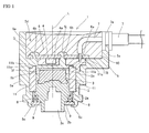
- FIG. 1 A section view of a rotation angle detecting device according to a first embodiment of the present invention.
- a rotation angle detecting device 1 is formed mainly of a rotation member 2, a magnet 3, a magnetism detecting package 4 containing a magneto-electric conversion element 4a, a housing 5, a circuit board 6, and a wiring 7.
- L indicates a rotation axis of the rotation member 2 and the magnet 3.
- the rotation member 2 rotates with an object under detection coupled thereto and is made of a synthetic resin material such as polyacetal.
- the rotation member 2 has a generally cylindrical shape and has a flange portion 2a without any breaks on the periphery.
- the rotation member 2 includes a hermetic member, later described, below the flange portion 2a in Fig. 1 .
- the rotation member 2 also includes a small-diameter portion 2b having a smaller diameter below the hermetic member.
- the small-diameter portion 2b is provided with a depression portion 2c for coupling to the object under detection.
- the magnet 3 is provided above the flange portion 2a in Fig. 1 .
- the magnet 3 is formed in a generally cylindrical shape.
- the magnet 3 has a flat face 3a perpendicular to the rotation axis L and the flat face 3a is magnetized with two poles such that the rotation axis L corresponds to the boundary between them.
- the magnet 3 is fixed to the rotation member 2, and is provided integrally with the rotation member 2 through insertion molding in the present embodiment.
- the magnet 3 is formed to rotate with the rotation of the rotation member 2 about the rotation axis L of the rotation member 2.
- the magnetism detecting package 4 is formed by covering the magneto-electric conversion element 4a such as a hall IC and an MR element with a synthetic resin.
- the magnetism detecting package 4 is provided on the circuit board 6, and the magneto-electric conversion element 4a of the magnetism detecting package 4 is electrically connected to the circuit board 6 through a lead, not shown, detects the magnitude of a magnetic field changing in response to the rotation of the magnet 3 rotating with the rotation of the rotation member 2, converts the detected result into a detection signal, and outputs the detection signal to the outside through the wiring 7 electrically connected to the circuit board 6.
- the housing 5 is made of a thermoplastic resin material such as polybutylene terephthalate and includes a base portion 5a formed in a generally cylindrical shape.
- a first accommodating portion 5b for rotatably accommodating the rotation member 2 is formed in the base portion 5a.
- a lower end portion 5c of the base portion 5a on the lower side forming the first accommodating portion 5b is bent inside the first accommodating portion 5b for swaging a washer, later described.
- a second accommodating portion 5d is formed for accommodating the magnetism detecting package 4 and the circuit board 6 on the upper side of the housing 5.
- the second accommodating portion 5d is formed by a wall portion 5e which surrounds the circuit board 6.
- the second accommodating portion 5d is filled with a filling member 10.
- the filling member is made of a resin such as epoxy and silicone which solidifies from liquid into solid.
- the filling member is an ultraviolet cure or thermosetting resin, for example, and the magnetism detecting package 4 and the circuit board 6 are hermetically housed and held within the second accommodating portion 5d.
- the first accommodating portion 5b and the second accommodating portion 5d are separated by a plate-shaped partition 5f to prevent communication between them.
- the magnetism detecting package 4 and the magnet 3 are opposite to each other with the partition 5f interposed between them.
- the first accommodating portion 5b, the second accommodating portion 5d, and the partition 5f are formed integrally.
- the first accommodating portion 5b is provided with a cylindrical metal member 11 which is formed integrally with the housing 5 through insertion molding.
- the metal member 11 is made of a non-magnetic material such as brass and rotatably supports the rotation member 2. Specifically, the metal member 11 has the function as a support member for rotatably supporting the rotation member 2 through abutment of the inner peripheral face of the metal member 11 on the outer periphery of the rotation member 2. A portion 11a of the metal member 11 is exposed within the second accommodating portion 5d.
- a creepage distance extending portion 11b is provided near the portion 11a of the metal member 11 that is exposed in the second accommodating portion 5d at a portion contained in the housing 5 for preventing the filling member 10 from leaching between the metal member 11 and the housing 5.
- the creepage distance extending portion 11b is provided on an end face 11c of the metal member 11 of tubular shape and inside the end face 11c.
- the creepage distance extending portion 11b is a protrusion portion 11b protruding from the metal member 11 toward the central axis of the cylindrical metal member 11.
- the protrusion portion 11b has a rectangular sectional shape.
- the protrusion portion 11b is provided on the end face 11c of the metal member 11 without any breaks.
- the protrusion portion 11b is formed by rotating about the center of the cylindrical metal member 11 and cutting the cylindrical metal member 11 from the outside by a cutting tool.
- the creepage distance extending portion 11b is provided.
- the creepage distance extending portion 11b increases the distance between the metal member 11 and the housing 5 from the exposed portion 11a to the first accommodating portion 5b, so that the filling member 10 can be stopped somewhere between the exposed portion 11a and the first accommodating portion 5b to prevent the entrance into the first accommodating portion 5b.
- the protrusion portion 11b is provided on the end face 11c of the tubular metal member 11, the machining through cutting is more easily performed and the metal member 11 can be formed at lower cost as compared with the formation on the tubular inner periphery of the tubular metal member 11.
- the housing 5 has a positioning portion 5j formed therein for determining the position to place the circuit board 6.
- the positioning portion 5j is provided within the second accommodating portion 5d.
- the positioning portion 5j has a protruding shape before the fixing of the circuit board 6 and is deformed through heating or the like in order to attach the circuit board 6, thereby preventing removal of the circuit board 6.
- the circuit board 6 is made of a hard circuit board, for example, is placed along the partition 5f of the housing 5, and is housed and fixed in the second accommodating portion 5d of the housing 5.
- the circuit board 6 has various electronic parts mounted thereon such as the magnetism detecting package 4 and a capacitor.
- Reference numeral 6a shows a hole through which the wiring 7 passes, and the wiring 7 passing through the hole 6a is electrically connected to a wiring pattern, not shown, of the circuit board 6 through soldering, not shown.
- Reference numeral 6b shows a positioning portion for determining the position to place the circuit board 6 and is a hole through which the positioning portion 5j of the housing 5 passes.
- the wiring 7 is formed by covering metal having favorable conductivity such as copper with an insulating material.
- Reference numeral 7a shows a packing made of an elastic member such as rubber and prevents leakage of the filling member 11 filling the second accommodating portion 5d.
- Reference numeral 8 shows a hermetic member made of an elastic member such as rubber and is realized by using a Y ring in the present embodiment.
- the Y ring 8 has a doughnut shape with a Y sectional shape and has the function of preventing introduction of a foreign matter such as water into the first accommodating portion 5b of the rotation angle detecting device 1.
- the elasticity of the Y ring 8 can suppress fluctuations of the magnet 3 due to vibrations to prevent erroneous detection with the magneto-electric conversion element 4a. Since the Y ring 8 is in contact over a small area with the rotation member 2 and the housing 5, the sliding resistance in the rotation of the rotation member 2 can be reduced.
- an X ring having an X sectional shape may be used. If the sliding resistance in the rotation of the rotation member 2 is not considered, an O ring 8 having a circular sectional shape may be used.
- Reference numeral 9 shows a washer which swages the lower end portion 5c of the housing 5 so as to cover the Y ring 8, thereby holding the rotation member 2 within the first accommodating portion 5b.
- the creepage distance extending portion 11b has the shape of the protrusion portion 11b protruding from the metal member 11 in the present embodiment, the present invention is not limited to the present embodiment.
- the creepage distance extending portion 11b may have a depression portion recessed in the metal member 11 or may have a depression and protrusion portion provided for the metal member 11.
- the position to provide the creepage distance extending portion 11b is not limited to the end face 11c of the metal member 11, and the creepage distance extending portion 11b may be provided on the outer peripheral face of the metal member 11.
- a depression portion or a depression and protrusion portion can be machined easily.
- the present invention can be utilized in the rotation angle detecting device for detecting the rotation angle of the object under detection.
Landscapes
- Physics & Mathematics (AREA)
- General Physics & Mathematics (AREA)
- Transmission And Conversion Of Sensor Element Output (AREA)
- Measurement Of Length, Angles, Or The Like Using Electric Or Magnetic Means (AREA)
Abstract
Description
- The present invention relates to a rotation angle detecting device for detecting the rotation angle of an object under detection.
- Known conventional rotation angle detecting devices include a throttle position sensor which detects the rotation angle of a shaft of a throttle valve (that is, the open/close angle of the throttle valve) when the shaft is rotated in association with the open/close operation of the throttle valve placed within an aspiration path of an internal combustion engine (see, for example, Patent Document 1).
- The rotation angle detecting device realized by the throttle position sensor described in
Patent Document 1 is mainly formed of a rotation shaft (rotation member) which rotates in response to the rotation of the shaft, a pair of magnets which rotates around the rotation shaft in synchronization with the rotation of the rotation shaft, a magneto-electric conversion element which is placed at the back of the rotation shaft and detects a change in the magnitude of a magnetic flux (the magnitude of a magnetic field) in association with the rotation operation of each of the magnets, a magnetic member of generally cylindrical cap shape including an annular portion having an insertion fixing portion for inserting and fixing a lower end portion of the rotation shaft and a tubular portion covering each of the magnets, and a housing of generally cylindrical cap shape including an annular plate portion having a penetration portion through which the rotation shaft passes and a cylindrical portion covering the outer periphery of the tubular portion and accommodating the magnetic member. - Since the rotation angle detecting device described in
Patent Document 1 includes the housing which rotatably supports the rotation member serving as the rotation shaft and the cover accommodating the magneto-electric conversion element, the rotation angle detecting device has the problem in that the number of parts constituting the device is increased to require higher assembly cost and parts cost to result in an increase in the overall cost. - To address the abovementioned problem, the present applicant has proposed a rotation angle detecting device capable of reducing cost in which a magnet rotating with a rotation member in response to the rotation of an object under detection is provided, a magneto-electric conversion element detecting the magnitude of a magnetic flux changing with the rotation of the magnet is used to output a detection signal according to the rotation of the object under detection, and a metal member rotatably supports the rotation member is formed integrally with a housing through insertion molding (see Patent Document 2).
-
- Patent Document 1:
JP-A-11-153404 - Patent Document 2:
JP-A-2007-327860 - The housing of the rotation angle detecting device described in
Patent Document 2 includes a first accommodating portion for accommodating the magnet and a second accommodating portion for accommodating the magneto-electric conversion element. The first accommodating portion and the second accommodating portion are separated from each other. The second accommodating portion is filled with a filling member, and the magneto-electric conversion element is hermetically sealed and held within the second accommodating portion of the housing. - The metal member needs to be held in the insertion molding with the housing. The portion for holding the metal member is exposed within the second accommodating portion after the molding of the housing.
- In filling the filling member into the second accommodating portion, the filling member may be introduced between the metal member and the housing from the portion exposed in the second accommodating portion of the metal member to enter the first accommodating portion. There has been a possibility that the filling member entering the first accommodating portion may prevent the rotation member with the magnet from being accommodated or may abut on the magnet or the rotation member to hinder the rotation of the magnet or the rotation member.
- To address this, in view of the abovementioned problem, it is an object of the present invention to provide a rotation angle detecting device capable of preventing a filling member filled into a second accommodating portion for accommodating a magneto-electric conversion element from entering a first accommodating portion for accommodating a magnet.
- The present invention provides a rotation angle detecting device including a rotation member, a magnet fixed to the rotation member and rotating in association with rotation of the rotation member, a magnetism detecting package placed opposite to the magnet and including a magneto-electric conversion element detecting a magnitude of a magnetic field of the magnet in the rotation of the magnet, a housing having a first accommodating portion rotatably accommodating the rotation member and a second accommodating portion accommodating the magnetism detecting package with a partition serving as a reference, a filling member filled to accommodate and hold hermetically the magnetism detecting package in the second accommodating portion, and a cylindrical metal member provided for the first accommodating portion to rotatably support the rotation member such that a portion of the metal member is exposed in the second accommodating portion, characterized in that a creepage distance extending portion is provided near the portion of the metal member exposed in the second accommodating portion at a portion contained in the housing, the creepage distance extending portion preventing the filling member from being introduced between the metal member and the housing.
- In the present invention, the creepage distance extending portion is a protrusion portion protruding from the metal member.
- In the present invention, the creepage distance extending portion is a depression portion recessed in the metal member.
- In the present invention, the creepage distance extending portion is a depression and protrusion portion provided for the metal member.
- In the present invention, the protrusion portion is provided on an end face of the tubular metal member. Advantage of the Invention
- According to the present invention, the intended object can be achieved. Specifically, it is possible to provide the rotation angle detecting device capable of preventing the filling member filled in the second accommodating portion for accommodating the magneto-electric conversion element from entering the first accommodating portion for accommodating the magnet.
- [
Fig. 1 ] A section view of a rotation angle detecting device according to a first embodiment of the present invention. - An embodiment of the present invention will hereinafter be described with the accompanying drawings.
- A rotation
angle detecting device 1 according to the present embodiment is formed mainly of arotation member 2, amagnet 3, amagnetism detecting package 4 containing a magneto-electric conversion element 4a, ahousing 5, acircuit board 6, and awiring 7. L indicates a rotation axis of therotation member 2 and themagnet 3. - The
rotation member 2 rotates with an object under detection coupled thereto and is made of a synthetic resin material such as polyacetal. - The
rotation member 2 has a generally cylindrical shape and has aflange portion 2a without any breaks on the periphery. Therotation member 2 includes a hermetic member, later described, below theflange portion 2a inFig. 1 . Therotation member 2 also includes a small-diameter portion 2b having a smaller diameter below the hermetic member. The small-diameter portion 2b is provided with adepression portion 2c for coupling to the object under detection. Themagnet 3 is provided above theflange portion 2a inFig. 1 . - The
magnet 3 is formed in a generally cylindrical shape. Themagnet 3 has aflat face 3a perpendicular to the rotation axis L and theflat face 3a is magnetized with two poles such that the rotation axis L corresponds to the boundary between them. Themagnet 3 is fixed to therotation member 2, and is provided integrally with therotation member 2 through insertion molding in the present embodiment. Themagnet 3 is formed to rotate with the rotation of therotation member 2 about the rotation axis L of therotation member 2. - The
magnetism detecting package 4 is formed by covering the magneto-electric conversion element 4a such as a hall IC and an MR element with a synthetic resin. Themagnetism detecting package 4 is provided on thecircuit board 6, and the magneto-electric conversion element 4a of themagnetism detecting package 4 is electrically connected to thecircuit board 6 through a lead, not shown, detects the magnitude of a magnetic field changing in response to the rotation of themagnet 3 rotating with the rotation of therotation member 2, converts the detected result into a detection signal, and outputs the detection signal to the outside through thewiring 7 electrically connected to thecircuit board 6. - The
housing 5 is made of a thermoplastic resin material such as polybutylene terephthalate and includes abase portion 5a formed in a generally cylindrical shape. A firstaccommodating portion 5b for rotatably accommodating therotation member 2 is formed in thebase portion 5a. - In
Fig. 1 , alower end portion 5c of thebase portion 5a on the lower side forming the first accommodatingportion 5b is bent inside the firstaccommodating portion 5b for swaging a washer, later described. - In
Fig. 1 , a secondaccommodating portion 5d is formed for accommodating themagnetism detecting package 4 and thecircuit board 6 on the upper side of thehousing 5. The secondaccommodating portion 5d is formed by awall portion 5e which surrounds thecircuit board 6. The secondaccommodating portion 5d is filled with a fillingmember 10. The filling member is made of a resin such as epoxy and silicone which solidifies from liquid into solid. The filling member is an ultraviolet cure or thermosetting resin, for example, and themagnetism detecting package 4 and thecircuit board 6 are hermetically housed and held within the secondaccommodating portion 5d. - The first
accommodating portion 5b and the second accommodatingportion 5d are separated by a plate-shaped partition 5f to prevent communication between them. Themagnetism detecting package 4 and themagnet 3 are opposite to each other with thepartition 5f interposed between them. The firstaccommodating portion 5b, the secondaccommodating portion 5d, and thepartition 5f are formed integrally. - The first accommodating
portion 5b is provided with acylindrical metal member 11 which is formed integrally with thehousing 5 through insertion molding. Themetal member 11 is made of a non-magnetic material such as brass and rotatably supports therotation member 2. Specifically, themetal member 11 has the function as a support member for rotatably supporting therotation member 2 through abutment of the inner peripheral face of themetal member 11 on the outer periphery of therotation member 2. Aportion 11a of themetal member 11 is exposed within the secondaccommodating portion 5d. - A creepage
distance extending portion 11b is provided near theportion 11a of themetal member 11 that is exposed in the secondaccommodating portion 5d at a portion contained in thehousing 5 for preventing thefilling member 10 from leaching between themetal member 11 and thehousing 5. - The creepage
distance extending portion 11b is provided on anend face 11c of themetal member 11 of tubular shape and inside theend face 11c. The creepagedistance extending portion 11b is aprotrusion portion 11b protruding from themetal member 11 toward the central axis of thecylindrical metal member 11. Theprotrusion portion 11b has a rectangular sectional shape. Theprotrusion portion 11b is provided on theend face 11c of themetal member 11 without any breaks. Theprotrusion portion 11b is formed by rotating about the center of thecylindrical metal member 11 and cutting thecylindrical metal member 11 from the outside by a cutting tool. - As described above, the creepage
distance extending portion 11b is provided. Thus, even when the fillingmember 10 is leached between themetal member 11 and thehousing 5 from theportion 11a of themetal member 11 exposed in the secondaccommodating portion 5d in filling the fillingmember 10 into the secondaccommodating portion 5d, the creepagedistance extending portion 11b increases the distance between themetal member 11 and thehousing 5 from the exposedportion 11a to the firstaccommodating portion 5b, so that the fillingmember 10 can be stopped somewhere between the exposedportion 11a and the firstaccommodating portion 5b to prevent the entrance into the firstaccommodating portion 5b. - Since the
protrusion portion 11b is provided on theend face 11c of thetubular metal member 11, the machining through cutting is more easily performed and themetal member 11 can be formed at lower cost as compared with the formation on the tubular inner periphery of thetubular metal member 11. - The
housing 5 has apositioning portion 5j formed therein for determining the position to place thecircuit board 6. Thepositioning portion 5j is provided within the secondaccommodating portion 5d. Thepositioning portion 5j has a protruding shape before the fixing of thecircuit board 6 and is deformed through heating or the like in order to attach thecircuit board 6, thereby preventing removal of thecircuit board 6. - The
circuit board 6 is made of a hard circuit board, for example, is placed along thepartition 5f of thehousing 5, and is housed and fixed in the secondaccommodating portion 5d of thehousing 5. Thecircuit board 6 has various electronic parts mounted thereon such as themagnetism detecting package 4 and a capacitor.Reference numeral 6a shows a hole through which thewiring 7 passes, and thewiring 7 passing through thehole 6a is electrically connected to a wiring pattern, not shown, of thecircuit board 6 through soldering, not shown.Reference numeral 6b shows a positioning portion for determining the position to place thecircuit board 6 and is a hole through which thepositioning portion 5j of thehousing 5 passes. - The
wiring 7 is formed by covering metal having favorable conductivity such as copper with an insulating material.Reference numeral 7a shows a packing made of an elastic member such as rubber and prevents leakage of the fillingmember 11 filling the secondaccommodating portion 5d. -
Reference numeral 8 shows a hermetic member made of an elastic member such as rubber and is realized by using a Y ring in the present embodiment. TheY ring 8 has a doughnut shape with a Y sectional shape and has the function of preventing introduction of a foreign matter such as water into the firstaccommodating portion 5b of the rotationangle detecting device 1. The elasticity of theY ring 8 can suppress fluctuations of themagnet 3 due to vibrations to prevent erroneous detection with the magneto-electric conversion element 4a. Since theY ring 8 is in contact over a small area with therotation member 2 and thehousing 5, the sliding resistance in the rotation of therotation member 2 can be reduced. Instead of theY ring 8, an X ring having an X sectional shape may be used. If the sliding resistance in the rotation of therotation member 2 is not considered, anO ring 8 having a circular sectional shape may be used. - Reference numeral 9 shows a washer which swages the
lower end portion 5c of thehousing 5 so as to cover theY ring 8, thereby holding therotation member 2 within the firstaccommodating portion 5b. - While the creepage
distance extending portion 11b has the shape of theprotrusion portion 11b protruding from themetal member 11 in the present embodiment, the present invention is not limited to the present embodiment. For example, the creepagedistance extending portion 11b may have a depression portion recessed in themetal member 11 or may have a depression and protrusion portion provided for themetal member 11. - The position to provide the creepage
distance extending portion 11b is not limited to theend face 11c of themetal member 11, and the creepagedistance extending portion 11b may be provided on the outer peripheral face of themetal member 11. When it is provided on the outer peripheral face of themetal member 11, a depression portion or a depression and protrusion portion can be machined easily. - The present invention can be utilized in the rotation angle detecting device for detecting the rotation angle of the object under detection.
-
- 1
- Rotation angle detecting device
- 2
- Rotation member
- 3
- Magnet
- 4
- Magnetism detecting package
- 4a
- Magneto-electric conversion element
- 5
- Housing
- 5b
- First accommodating portion
- 5d
- Second accommodating portion
- 5f
- Partition
- 10
- Filling member
- 11
- Metal member
- 11a
- Portion (Exposed portion)
- 11b
- Creepage distance extending portion
- 11c
- End face
Claims (5)
- A rotation angle detecting device comprising a rotation member, a magnet fixed to the rotation member and rotating in association with rotation of the rotation member, a magnetism detecting package placed opposite to the magnet and including a magneto-electric conversion element detecting a magnitude of a magnetic field of the magnet in the rotation of the magnet, a housing having a first accommodating portion rotatably accommodating the rotation member and a second accommodating portion accommodating the magnetism detecting package with a partition serving as a reference, a filling member filled to accommodate and hold hermetically the magnetism detecting package in the second accommodating portion, and a cylindrical metal member provided for the first accommodating portion to rotatably support the rotation member such that a portion of the metal member is exposed in the second accommodating portion,
characterized in that a creepage distance extending portion is provided near the portion of the metal member exposed in the second accommodating portion at a portion contained in the housing, the creepage distance extending portion preventing the filling member from being introduced between the metal member and the housing. - The rotation angle detecting device according to claim 1, characterized in that the creepage distance extending portion is a protrusion portion protruding from the metal member.
- The rotation angle detecting device according to claim 1, characterized in that the creepage distance extending portion is a depression portion recessed in the metal member.
- The rotation angle detecting device according to claim 1, characterized in that the creepage distance extending portion is a depression and protrusion portion provided for the metal member.
- The rotation angle detecting device according to claim 2, characterized in that the protrusion portion is provided on an end face of the tubular metal member.
Applications Claiming Priority (2)
| Application Number | Priority Date | Filing Date | Title |
|---|---|---|---|
| JP2009227390A JP5344375B2 (en) | 2009-09-30 | 2009-09-30 | Rotation angle detector |
| PCT/JP2010/066028 WO2011040249A1 (en) | 2009-09-30 | 2010-09-16 | Rotation angle detecting device |
Publications (3)
| Publication Number | Publication Date |
|---|---|
| EP2485013A1 true EP2485013A1 (en) | 2012-08-08 |
| EP2485013A4 EP2485013A4 (en) | 2016-08-03 |
| EP2485013B1 EP2485013B1 (en) | 2017-09-13 |
Family
ID=43826075
Family Applications (1)
| Application Number | Title | Priority Date | Filing Date |
|---|---|---|---|
| EP10820368.8A Active EP2485013B1 (en) | 2009-09-30 | 2010-09-16 | Rotation angle detecting device |
Country Status (6)
| Country | Link |
|---|---|
| US (1) | US9000758B2 (en) |
| EP (1) | EP2485013B1 (en) |
| JP (1) | JP5344375B2 (en) |
| CN (1) | CN102549387B (en) |
| IN (1) | IN2012DN02718A (en) |
| WO (1) | WO2011040249A1 (en) |
Families Citing this family (10)
| Publication number | Priority date | Publication date | Assignee | Title |
|---|---|---|---|---|
| JP5800207B2 (en) * | 2013-05-10 | 2015-10-28 | 株式会社デンソー | Rotation position detector |
| WO2016110918A1 (en) * | 2015-01-05 | 2016-07-14 | パナソニックIpマネジメント株式会社 | Rotation angle detection device and rotation angle dfetection unit using same |
| JP2018088727A (en) * | 2016-11-28 | 2018-06-07 | 日本電産サンキョー株式会社 | Geared motor |
| JP6741611B2 (en) * | 2017-02-20 | 2020-08-19 | 株式会社不二工機 | Motorized valve |
| JP6826727B2 (en) | 2017-03-31 | 2021-02-10 | 株式会社不二工機 | Solenoid valve |
| SE542616C2 (en) * | 2018-09-27 | 2020-06-16 | Leine & Linde Ab | Rotary encoder and method for manufacturing a rotary encoder |
| EP3683551B1 (en) * | 2019-01-17 | 2021-03-10 | Dr. Johannes Heidenhain GmbH | Sampling unit for an angle measuring device |
| JP7194809B2 (en) | 2019-03-29 | 2022-12-22 | 日本碍子株式会社 | Sensor element of gas sensor |
| CN114729822B (en) * | 2019-12-10 | 2024-03-08 | 三菱电机株式会社 | Magnetism generating unit, rotation angle detection device and rotating motor |
| WO2025064197A1 (en) | 2023-09-02 | 2025-03-27 | Bristol-Myers Squibb Company | Substituted azetidinyl oxoisoindolinyl piperidine-2,6-dione compounds |
Family Cites Families (14)
| Publication number | Priority date | Publication date | Assignee | Title |
|---|---|---|---|---|
| JP3079528B2 (en) | 1996-02-28 | 2000-08-21 | 日本精機株式会社 | Rotation detection device |
| JPH11153404A (en) * | 1997-11-21 | 1999-06-08 | Teikoku Tsushin Kogyo Co Ltd | Rotation angle sensor |
| JP2001289610A (en) * | 1999-11-01 | 2001-10-19 | Denso Corp | Rotation angle detector |
| JP4433886B2 (en) * | 2004-06-02 | 2010-03-17 | 株式会社デンソー | Rotation angle detector |
| US7019517B2 (en) * | 2004-07-20 | 2006-03-28 | Honeywell International Inc. | Offset magnet rotary position sensor |
| US7230419B2 (en) * | 2005-06-03 | 2007-06-12 | Delphi Technologies, Inc. | Rotary position sensor |
| JP2007327860A (en) * | 2006-06-08 | 2007-12-20 | Nippon Seiki Co Ltd | Angle detector |
| JP4743040B2 (en) | 2006-08-08 | 2011-08-10 | 株式会社デンソー | Rotation angle detector |
| JP5035746B2 (en) * | 2006-12-28 | 2012-09-26 | 日本精機株式会社 | Rotation detector |
| JP4979449B2 (en) * | 2007-04-27 | 2012-07-18 | キヤノン株式会社 | Fixing device |
| JP5112997B2 (en) * | 2008-09-12 | 2013-01-09 | Ntn株式会社 | Rotation angle detection unit |
| JP5189063B2 (en) * | 2009-11-16 | 2013-04-24 | 愛三工業株式会社 | Rotation angle detection device and throttle control device |
| JP5801566B2 (en) * | 2011-02-15 | 2015-10-28 | 株式会社ミクニ | Rotation angle detector |
| JP5741961B2 (en) * | 2012-10-24 | 2015-07-01 | 株式会社デンソー | Rotation angle detection device and rotation drive device using the same |
-
2009
- 2009-09-30 JP JP2009227390A patent/JP5344375B2/en active Active
-
2010
- 2010-09-16 US US13/394,718 patent/US9000758B2/en active Active
- 2010-09-16 EP EP10820368.8A patent/EP2485013B1/en active Active
- 2010-09-16 CN CN201080043827.0A patent/CN102549387B/en not_active Expired - Fee Related
- 2010-09-16 WO PCT/JP2010/066028 patent/WO2011040249A1/en not_active Ceased
-
2012
- 2012-03-29 IN IN2718DEN2012 patent/IN2012DN02718A/en unknown
Also Published As
| Publication number | Publication date |
|---|---|
| WO2011040249A1 (en) | 2011-04-07 |
| US9000758B2 (en) | 2015-04-07 |
| IN2012DN02718A (en) | 2015-09-11 |
| EP2485013A4 (en) | 2016-08-03 |
| EP2485013B1 (en) | 2017-09-13 |
| CN102549387A (en) | 2012-07-04 |
| CN102549387B (en) | 2015-04-08 |
| JP5344375B2 (en) | 2013-11-20 |
| JP2011075413A (en) | 2011-04-14 |
| US20120169325A1 (en) | 2012-07-05 |
Similar Documents
| Publication | Publication Date | Title |
|---|---|---|
| US9000758B2 (en) | Rotation angle detecting device | |
| US7190160B2 (en) | Rotation sensor | |
| CN1921274B (en) | Rotary electric machine equipped with magnetic sensors and flat motor | |
| CN104205584B (en) | Motor | |
| EP2413111A1 (en) | Liquid level detection device | |
| CN104024812B (en) | Liquid level sensor | |
| CN104272067B (en) | Liquid level sensor | |
| EP2940437A1 (en) | Liquid level detection device | |
| EP2508840A1 (en) | Position detecting device | |
| US6836111B2 (en) | Sensor assembly with a universal sensor module for sensing angular position of an object | |
| JP2011141146A (en) | Liquid level detector and manufacturing method the same | |
| JPH11153404A (en) | Rotation angle sensor | |
| JP2013113785A (en) | Rotation angle detection device | |
| JP2007132920A (en) | Liquid level detector | |
| JP2006153679A (en) | Liquid level detector | |
| JP4867531B2 (en) | Liquid level detector | |
| JP4165386B2 (en) | Electronic component holding structure | |
| JP7106051B2 (en) | Rotation detection device and method for manufacturing rotation detection device | |
| JP2008185501A (en) | Rotation detector | |
| JP4973058B2 (en) | Liquid level detector | |
| JP2010169652A (en) | Rotation angle detector | |
| JP2019148502A (en) | Liquid level detection device | |
| KR102584905B1 (en) | Motor | |
| JP7173032B2 (en) | Rotation angle detector | |
| JP2009098047A (en) | Lead terminal connecting structure |
Legal Events
| Date | Code | Title | Description |
|---|---|---|---|
| PUAI | Public reference made under article 153(3) epc to a published international application that has entered the european phase |
Free format text: ORIGINAL CODE: 0009012 |
|
| 17P | Request for examination filed |
Effective date: 20120314 |
|
| AK | Designated contracting states |
Kind code of ref document: A1 Designated state(s): AL AT BE BG CH CY CZ DE DK EE ES FI FR GB GR HR HU IE IS IT LI LT LU LV MC MK MT NL NO PL PT RO SE SI SK SM TR |
|
| DAX | Request for extension of the european patent (deleted) | ||
| RA4 | Supplementary search report drawn up and despatched (corrected) |
Effective date: 20160705 |
|
| RIC1 | Information provided on ipc code assigned before grant |
Ipc: G01D 11/24 20060101ALI20160630BHEP Ipc: G01D 5/14 20060101AFI20160630BHEP |
|
| GRAP | Despatch of communication of intention to grant a patent |
Free format text: ORIGINAL CODE: EPIDOSNIGR1 |
|
| INTG | Intention to grant announced |
Effective date: 20170504 |
|
| RIN1 | Information on inventor provided before grant (corrected) |
Inventor name: IWAHASHI, MASARU |
|
| GRAS | Grant fee paid |
Free format text: ORIGINAL CODE: EPIDOSNIGR3 |
|
| GRAA | (expected) grant |
Free format text: ORIGINAL CODE: 0009210 |
|
| AK | Designated contracting states |
Kind code of ref document: B1 Designated state(s): AL AT BE BG CH CY CZ DE DK EE ES FI FR GB GR HR HU IE IS IT LI LT LU LV MC MK MT NL NO PL PT RO SE SI SK SM TR |
|
| REG | Reference to a national code |
Ref country code: GB Ref legal event code: FG4D |
|
| REG | Reference to a national code |
Ref country code: CH Ref legal event code: EP |
|
| REG | Reference to a national code |
Ref country code: IE Ref legal event code: FG4D |
|
| REG | Reference to a national code |
Ref country code: FR Ref legal event code: PLFP Year of fee payment: 8 |
|
| REG | Reference to a national code |
Ref country code: AT Ref legal event code: REF Ref document number: 928605 Country of ref document: AT Kind code of ref document: T Effective date: 20171015 |
|
| REG | Reference to a national code |
Ref country code: DE Ref legal event code: R096 Ref document number: 602010045260 Country of ref document: DE |
|
| REG | Reference to a national code |
Ref country code: NL Ref legal event code: MP Effective date: 20170913 |
|
| REG | Reference to a national code |
Ref country code: LT Ref legal event code: MG4D |
|
| PG25 | Lapsed in a contracting state [announced via postgrant information from national office to epo] |
Ref country code: LT Free format text: LAPSE BECAUSE OF FAILURE TO SUBMIT A TRANSLATION OF THE DESCRIPTION OR TO PAY THE FEE WITHIN THE PRESCRIBED TIME-LIMIT Effective date: 20170913 Ref country code: HR Free format text: LAPSE BECAUSE OF FAILURE TO SUBMIT A TRANSLATION OF THE DESCRIPTION OR TO PAY THE FEE WITHIN THE PRESCRIBED TIME-LIMIT Effective date: 20170913 Ref country code: NO Free format text: LAPSE BECAUSE OF FAILURE TO SUBMIT A TRANSLATION OF THE DESCRIPTION OR TO PAY THE FEE WITHIN THE PRESCRIBED TIME-LIMIT Effective date: 20171213 Ref country code: FI Free format text: LAPSE BECAUSE OF FAILURE TO SUBMIT A TRANSLATION OF THE DESCRIPTION OR TO PAY THE FEE WITHIN THE PRESCRIBED TIME-LIMIT Effective date: 20170913 Ref country code: SE Free format text: LAPSE BECAUSE OF FAILURE TO SUBMIT A TRANSLATION OF THE DESCRIPTION OR TO PAY THE FEE WITHIN THE PRESCRIBED TIME-LIMIT Effective date: 20170913 |
|
| REG | Reference to a national code |
Ref country code: AT Ref legal event code: MK05 Ref document number: 928605 Country of ref document: AT Kind code of ref document: T Effective date: 20170913 |
|
| PG25 | Lapsed in a contracting state [announced via postgrant information from national office to epo] |
Ref country code: BG Free format text: LAPSE BECAUSE OF FAILURE TO SUBMIT A TRANSLATION OF THE DESCRIPTION OR TO PAY THE FEE WITHIN THE PRESCRIBED TIME-LIMIT Effective date: 20171213 Ref country code: ES Free format text: LAPSE BECAUSE OF FAILURE TO SUBMIT A TRANSLATION OF THE DESCRIPTION OR TO PAY THE FEE WITHIN THE PRESCRIBED TIME-LIMIT Effective date: 20170913 Ref country code: LV Free format text: LAPSE BECAUSE OF FAILURE TO SUBMIT A TRANSLATION OF THE DESCRIPTION OR TO PAY THE FEE WITHIN THE PRESCRIBED TIME-LIMIT Effective date: 20170913 Ref country code: GR Free format text: LAPSE BECAUSE OF FAILURE TO SUBMIT A TRANSLATION OF THE DESCRIPTION OR TO PAY THE FEE WITHIN THE PRESCRIBED TIME-LIMIT Effective date: 20171214 |
|
| PG25 | Lapsed in a contracting state [announced via postgrant information from national office to epo] |
Ref country code: NL Free format text: LAPSE BECAUSE OF FAILURE TO SUBMIT A TRANSLATION OF THE DESCRIPTION OR TO PAY THE FEE WITHIN THE PRESCRIBED TIME-LIMIT Effective date: 20170913 |
|
| PG25 | Lapsed in a contracting state [announced via postgrant information from national office to epo] |
Ref country code: PL Free format text: LAPSE BECAUSE OF FAILURE TO SUBMIT A TRANSLATION OF THE DESCRIPTION OR TO PAY THE FEE WITHIN THE PRESCRIBED TIME-LIMIT Effective date: 20170913 Ref country code: CZ Free format text: LAPSE BECAUSE OF FAILURE TO SUBMIT A TRANSLATION OF THE DESCRIPTION OR TO PAY THE FEE WITHIN THE PRESCRIBED TIME-LIMIT Effective date: 20170913 Ref country code: RO Free format text: LAPSE BECAUSE OF FAILURE TO SUBMIT A TRANSLATION OF THE DESCRIPTION OR TO PAY THE FEE WITHIN THE PRESCRIBED TIME-LIMIT Effective date: 20170913 |
|
| REG | Reference to a national code |
Ref country code: CH Ref legal event code: PL |
|
| PG25 | Lapsed in a contracting state [announced via postgrant information from national office to epo] |
Ref country code: AT Free format text: LAPSE BECAUSE OF FAILURE TO SUBMIT A TRANSLATION OF THE DESCRIPTION OR TO PAY THE FEE WITHIN THE PRESCRIBED TIME-LIMIT Effective date: 20170913 Ref country code: IS Free format text: LAPSE BECAUSE OF FAILURE TO SUBMIT A TRANSLATION OF THE DESCRIPTION OR TO PAY THE FEE WITHIN THE PRESCRIBED TIME-LIMIT Effective date: 20180113 Ref country code: SK Free format text: LAPSE BECAUSE OF FAILURE TO SUBMIT A TRANSLATION OF THE DESCRIPTION OR TO PAY THE FEE WITHIN THE PRESCRIBED TIME-LIMIT Effective date: 20170913 Ref country code: IT Free format text: LAPSE BECAUSE OF FAILURE TO SUBMIT A TRANSLATION OF THE DESCRIPTION OR TO PAY THE FEE WITHIN THE PRESCRIBED TIME-LIMIT Effective date: 20170913 Ref country code: EE Free format text: LAPSE BECAUSE OF FAILURE TO SUBMIT A TRANSLATION OF THE DESCRIPTION OR TO PAY THE FEE WITHIN THE PRESCRIBED TIME-LIMIT Effective date: 20170913 Ref country code: SM Free format text: LAPSE BECAUSE OF FAILURE TO SUBMIT A TRANSLATION OF THE DESCRIPTION OR TO PAY THE FEE WITHIN THE PRESCRIBED TIME-LIMIT Effective date: 20170913 |
|
| REG | Reference to a national code |
Ref country code: DE Ref legal event code: R097 Ref document number: 602010045260 Country of ref document: DE |
|
| REG | Reference to a national code |
Ref country code: IE Ref legal event code: MM4A |
|
| REG | Reference to a national code |
Ref country code: BE Ref legal event code: MM Effective date: 20170930 |
|
| PG25 | Lapsed in a contracting state [announced via postgrant information from national office to epo] |
Ref country code: MC Free format text: LAPSE BECAUSE OF FAILURE TO SUBMIT A TRANSLATION OF THE DESCRIPTION OR TO PAY THE FEE WITHIN THE PRESCRIBED TIME-LIMIT Effective date: 20170913 Ref country code: LU Free format text: LAPSE BECAUSE OF NON-PAYMENT OF DUE FEES Effective date: 20170916 |
|
| PLBE | No opposition filed within time limit |
Free format text: ORIGINAL CODE: 0009261 |
|
| STAA | Information on the status of an ep patent application or granted ep patent |
Free format text: STATUS: NO OPPOSITION FILED WITHIN TIME LIMIT |
|
| PG25 | Lapsed in a contracting state [announced via postgrant information from national office to epo] |
Ref country code: LI Free format text: LAPSE BECAUSE OF NON-PAYMENT OF DUE FEES Effective date: 20170930 Ref country code: CH Free format text: LAPSE BECAUSE OF NON-PAYMENT OF DUE FEES Effective date: 20170930 Ref country code: IE Free format text: LAPSE BECAUSE OF NON-PAYMENT OF DUE FEES Effective date: 20170916 Ref country code: DK Free format text: LAPSE BECAUSE OF FAILURE TO SUBMIT A TRANSLATION OF THE DESCRIPTION OR TO PAY THE FEE WITHIN THE PRESCRIBED TIME-LIMIT Effective date: 20170913 |
|
| REG | Reference to a national code |
Ref country code: FR Ref legal event code: PLFP Year of fee payment: 9 |
|
| 26N | No opposition filed |
Effective date: 20180614 |
|
| PG25 | Lapsed in a contracting state [announced via postgrant information from national office to epo] |
Ref country code: BE Free format text: LAPSE BECAUSE OF NON-PAYMENT OF DUE FEES Effective date: 20170930 |
|
| PG25 | Lapsed in a contracting state [announced via postgrant information from national office to epo] |
Ref country code: MT Free format text: LAPSE BECAUSE OF NON-PAYMENT OF DUE FEES Effective date: 20170916 |
|
| PG25 | Lapsed in a contracting state [announced via postgrant information from national office to epo] |
Ref country code: SI Free format text: LAPSE BECAUSE OF FAILURE TO SUBMIT A TRANSLATION OF THE DESCRIPTION OR TO PAY THE FEE WITHIN THE PRESCRIBED TIME-LIMIT Effective date: 20170913 |
|
| PG25 | Lapsed in a contracting state [announced via postgrant information from national office to epo] |
Ref country code: HU Free format text: LAPSE BECAUSE OF FAILURE TO SUBMIT A TRANSLATION OF THE DESCRIPTION OR TO PAY THE FEE WITHIN THE PRESCRIBED TIME-LIMIT; INVALID AB INITIO Effective date: 20100916 |
|
| PG25 | Lapsed in a contracting state [announced via postgrant information from national office to epo] |
Ref country code: CY Free format text: LAPSE BECAUSE OF NON-PAYMENT OF DUE FEES Effective date: 20170913 |
|
| PG25 | Lapsed in a contracting state [announced via postgrant information from national office to epo] |
Ref country code: MK Free format text: LAPSE BECAUSE OF FAILURE TO SUBMIT A TRANSLATION OF THE DESCRIPTION OR TO PAY THE FEE WITHIN THE PRESCRIBED TIME-LIMIT Effective date: 20170913 |
|
| PG25 | Lapsed in a contracting state [announced via postgrant information from national office to epo] |
Ref country code: TR Free format text: LAPSE BECAUSE OF FAILURE TO SUBMIT A TRANSLATION OF THE DESCRIPTION OR TO PAY THE FEE WITHIN THE PRESCRIBED TIME-LIMIT Effective date: 20170913 |
|
| PG25 | Lapsed in a contracting state [announced via postgrant information from national office to epo] |
Ref country code: PT Free format text: LAPSE BECAUSE OF FAILURE TO SUBMIT A TRANSLATION OF THE DESCRIPTION OR TO PAY THE FEE WITHIN THE PRESCRIBED TIME-LIMIT Effective date: 20170913 |
|
| PG25 | Lapsed in a contracting state [announced via postgrant information from national office to epo] |
Ref country code: AL Free format text: LAPSE BECAUSE OF FAILURE TO SUBMIT A TRANSLATION OF THE DESCRIPTION OR TO PAY THE FEE WITHIN THE PRESCRIBED TIME-LIMIT Effective date: 20170913 |
|
| PGFP | Annual fee paid to national office [announced via postgrant information from national office to epo] |
Ref country code: GB Payment date: 20220728 Year of fee payment: 13 |
|
| PGFP | Annual fee paid to national office [announced via postgrant information from national office to epo] |
Ref country code: FR Payment date: 20220808 Year of fee payment: 13 |
|
| GBPC | Gb: european patent ceased through non-payment of renewal fee |
Effective date: 20230916 |
|
| PG25 | Lapsed in a contracting state [announced via postgrant information from national office to epo] |
Ref country code: GB Free format text: LAPSE BECAUSE OF NON-PAYMENT OF DUE FEES Effective date: 20230916 |
|
| PG25 | Lapsed in a contracting state [announced via postgrant information from national office to epo] |
Ref country code: GB Free format text: LAPSE BECAUSE OF NON-PAYMENT OF DUE FEES Effective date: 20230916 Ref country code: FR Free format text: LAPSE BECAUSE OF NON-PAYMENT OF DUE FEES Effective date: 20230930 |
|
| PGFP | Annual fee paid to national office [announced via postgrant information from national office to epo] |
Ref country code: DE Payment date: 20250730 Year of fee payment: 16 |