EP2484997A2 - A cooling device with a cover in the liner - Google Patents
A cooling device with a cover in the liner Download PDFInfo
- Publication number
- EP2484997A2 EP2484997A2 EP12152273A EP12152273A EP2484997A2 EP 2484997 A2 EP2484997 A2 EP 2484997A2 EP 12152273 A EP12152273 A EP 12152273A EP 12152273 A EP12152273 A EP 12152273A EP 2484997 A2 EP2484997 A2 EP 2484997A2
- Authority
- EP
- European Patent Office
- Prior art keywords
- cooling device
- cover
- cut
- pin
- liner
- Prior art date
- Legal status (The legal status is an assumption and is not a legal conclusion. Google has not performed a legal analysis and makes no representation as to the accuracy of the status listed.)
- Withdrawn
Links
- 238000001816 cooling Methods 0.000 title claims abstract description 37
- 238000000034 method Methods 0.000 description 6
- 238000005452 bending Methods 0.000 description 1
- 230000006866 deterioration Effects 0.000 description 1
- 230000000694 effects Effects 0.000 description 1
- 230000000007 visual effect Effects 0.000 description 1
Images


Classifications
-
- F—MECHANICAL ENGINEERING; LIGHTING; HEATING; WEAPONS; BLASTING
- F25—REFRIGERATION OR COOLING; COMBINED HEATING AND REFRIGERATION SYSTEMS; HEAT PUMP SYSTEMS; MANUFACTURE OR STORAGE OF ICE; LIQUEFACTION SOLIDIFICATION OF GASES
- F25D—REFRIGERATORS; COLD ROOMS; ICE-BOXES; COOLING OR FREEZING APPARATUS NOT OTHERWISE PROVIDED FOR
- F25D23/00—General constructional features
- F25D23/06—Walls
- F25D23/065—Details
- F25D23/067—Supporting elements
-
- F—MECHANICAL ENGINEERING; LIGHTING; HEATING; WEAPONS; BLASTING
- F25—REFRIGERATION OR COOLING; COMBINED HEATING AND REFRIGERATION SYSTEMS; HEAT PUMP SYSTEMS; MANUFACTURE OR STORAGE OF ICE; LIQUEFACTION SOLIDIFICATION OF GASES
- F25D—REFRIGERATORS; COLD ROOMS; ICE-BOXES; COOLING OR FREEZING APPARATUS NOT OTHERWISE PROVIDED FOR
- F25D23/00—General constructional features
- F25D23/02—Doors; Covers
- F25D23/025—Secondary closures
-
- F—MECHANICAL ENGINEERING; LIGHTING; HEATING; WEAPONS; BLASTING
- F25—REFRIGERATION OR COOLING; COMBINED HEATING AND REFRIGERATION SYSTEMS; HEAT PUMP SYSTEMS; MANUFACTURE OR STORAGE OF ICE; LIQUEFACTION SOLIDIFICATION OF GASES
- F25C—PRODUCING, WORKING OR HANDLING ICE
- F25C2400/00—Auxiliary features or devices for producing, working or handling ice
- F25C2400/10—Refrigerator units
Definitions
- the present invention relates to a cooling device comprising at least one fixation member which is assembled inside the liner of cooling device and which has a pin; and a cover which is connected to the fixation member through a connection part which is in connection with said pin.
- cooling device liners for facilitating the usage of the cooling device and for making the cooling device more functional.
- the most frequently used one among these embodiments is the shelf applications placed inside liners.
- shelves are placed inside liners.
- a certain distance is left between two liners.
- Another embodiment applied inside the liner is the cover application. Covers, which are assembled inside the liner, are used for forming a separate compartment inside the liner, for hiding pluralities of members and for making inside of the liner more aesthetic.
- Covers which are assembled inside the liner of cooling device, are separated into two types called flexible covers and rigid covers according to the physical characteristics thereof.
- the temporary shape changing characteristic of the cover is utilized.
- the flexible cover is bended and it is connected to the connection members inside the liner.
- the connection members are connected onto the cover; afterwards, the cover is assembled inside the liner.
- US2003019873 in relation to said application.
- said application firstly, particularly designed hinges are connected to the housings existing on the cover; afterwards, the assembly of the cover to the housings on the cooling device is realized.
- a separate process is applied for the assembly of pins and there becomes time loss.
- the present invention relates to an arrangement which provides the rigid covers to be assembled inside the cooling device liner in a simple manner, in order to eliminate the abovementioned drawbacks and in order to bring new advantages in the related technical field.
- the main object of the present invention is to provide an arrangement which provides the rigid covers, which are assembled inside the cooling device liner, to be connected to the pins, existing inside the liner, in a simple manner.
- another object of the present invention is to provide an arrangement which provides said cover to rotate in a simple manner on the pin after the assembly of the cover is realized.
- the present invention relates to a cooling device comprising at least one fixation member which is assembled inside the liner of the cooling device and which has a pin; and a cover which is connected to the fixation member through a connection part which is in connection with said pin, characterized in that , it comprises at least one cut-out embodied on said connection part, at least one fixation piece connected to the cover so as to cover said cut-out at least partially so as to define a pin housing where the pin is restrained.
- the cut-out has a cross section similar to a semi-circle.
- the cut-out begins from the inlet part of the connection part, wherein a pin enters, and the cut-out extends partially along the connection part.
- the cut-out begins from the inlet part of the connection part, wherein a pin enters, and the cut-out extends partially along the connection part.
- the fixation piece comprises a housing part which is embodied so as to partially or completely cover the cut-out; and an assembly part which extends at the continuation of said housing part.
- said housing part has a cross section similar to a semi-circle so as to be compliant with the cut-out.
- a support bar is provided which extends substantially parallel to the connection part at the lower alignment of the connection part and whereon the fixation piece is assembled.
- a screw housing is provided on said assembly part; and at least one connection opening is provided on the support bar so as to correspond to said screw housing.
- At least one screw is provided which is connected to the screw housing and to the connection opening; in order to provide the fixation member to be connected to the support bar through the screw housing.
- the cover is positioned inside the liner so as to be able to cover at least one ice machine and so as to be able to cover at least one storage region adjacent to said ice machine and so as to control the access to these items.
- said cooling device is a refrigerator.
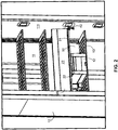
- FIG. 1 and Figure 2 there is a cover (20) which is assembled inside the liner (11) of the cooling device (10). Inside the liner (11), there is an ice machine (12) whose assembly is realized. There is a shelf (13) which is connected inside the liner (11) so as to be adjacent to said ice machine (12). The shelf (13), which is connected so as to contact with the lower surface of the ice machine (12), defines a storage region (50) so as to be adjacent to the ice machine (12).
- Said cover (20) whereon arrangements are realized.
- Said cover (20) has a rectangular shape.
- There is a connection part (21) which is embodied on the cover (20) so as to form one of the long edges of the cover (20).
- the connection part (21) has a cylindrical form.
- There is a pin housing (211) which is embodied on the connection part (21). Said pin housing (211) is at the connection part's (21) side close to the first edge (24).
- fixation member (40) which is connected to the connection surface (111) inside the cooling device (10) liner (11).
- the fixation member (40) comprises pluralities of items which are embodied on a rectangular plate.
- connection openings (42) which are embodied on the body of the fixation member (40).
- stopper member (43) which is embodied so as to be adjacent to said upper pin.
- connection region (30) can be seen where the related arrangement is realized on the cover (20).
- a cut-out (31) which is embodied at the end region of the connection part (21). Said cut-out (31) is obtained by removing a small piece in semi-cylinder form from the end region of the connection part (21).
- the cut-out (31) has a cross section which is in the form of a semi-circle.
- connection opening (35) which is embodied on the support bar (22).
- Said connection opening (35) is positioned in the same alignment with the cut-out (31) in the vertical direction.
- There is a fixation piece (32) which is connected to the support bar (22).
- Said fixation piece (32) is formed by the joining of a rectangular assembly part (322) and a semi-circular housing part (321).
- Said housing part (321) has a semi-circular cross section similar to the cut-out (31).
- said cover (20) is assembled inside the liner (11) through the connection part (21).
- the pin housing (211) existing on the connection part (21) forms a housing for the upper pin on the fixation member (40).
- the lower pin (41) helps the cover (20) to preserve the position thereof when in closed position.
- the stopper member (43) helps the cover to preserve the position thereof when the cover is in open position.
- the application of the arrangement regarding the assembly of the cover (20) is as follows.
- the screw housing (33) existing on the assembly part (322) and the connection opening (35) existing on the support bar (22) are brought one above the other so as to be concentric.
- a screw (34) is connected to the screw housing (33) and thus to the connection opening (35).
- the fixation piece (32) is connected onto the support bar (22).
- the cut-out (31) and the fixation piece's (32) housing part (321) are brought together.
- the cut-out (31) which is open and which is in semi-circular form, is partially or completely closed with the help of the housing part (321).
- the housing part (321) which joins with the cut-out (31) defines a new pin housing.
- the assembly of said cover (20) inside the liner (11) is as follows.
- the pin housing (211) existing on the cover's (20) connection part (21) is connected with the upper pin existing on the fixation member (40).
- the cut-out (31) on the cover (20) is brought to the same alignment with the upper pin existing on the fixation member (40).
- the fixation piece (32) is connected to the support bar (22).
- the upper pin is restrained inside the cut-out (31).
- the cover (20) which is connected to both of the upper pins, is assembled inside the liner (11).
- the cover (20) can move on the upper pins, it can rotate in an easy manner on the axis defined by the connection part (21).
- the cover (20) is positioned inside the liner (11) so as to be able to cover the ice machine (12) and so as to be able to cover the storage regions (50) embodied around the ice machine (12).
- a visual integrity is provided and at the same time, an aesthetic view is provided to the liner (11).
Landscapes
- Engineering & Computer Science (AREA)
- Chemical & Material Sciences (AREA)
- Combustion & Propulsion (AREA)
- Physics & Mathematics (AREA)
- Mechanical Engineering (AREA)
- Thermal Sciences (AREA)
- General Engineering & Computer Science (AREA)
- Cooling Or The Like Of Semiconductors Or Solid State Devices (AREA)
- Connection Of Plates (AREA)
- Devices That Are Associated With Refrigeration Equipment (AREA)
Abstract
Description
- The present invention relates to a cooling device comprising at least one fixation member which is assembled inside the liner of cooling device and which has a pin; and a cover which is connected to the fixation member through a connection part which is in connection with said pin.
- There are pluralities of embodiments assembled inside cooling device liners for facilitating the usage of the cooling device and for making the cooling device more functional. The most frequently used one among these embodiments is the shelf applications placed inside liners. According to the usage purposes of shelves, shelves are placed inside liners. In the direction of the usage purposes of shelves, a certain distance is left between two liners. Another embodiment applied inside the liner is the cover application. Covers, which are assembled inside the liner, are used for forming a separate compartment inside the liner, for hiding pluralities of members and for making inside of the liner more aesthetic.
- Covers, which are assembled inside the liner of cooling device, are separated into two types called flexible covers and rigid covers according to the physical characteristics thereof. During the assembly of the flexible covers inside the liner, the temporary shape changing characteristic of the cover is utilized. During assembly, the flexible cover is bended and it is connected to the connection members inside the liner. In the assembly of rigid covers, first of all, the connection members are connected onto the cover; afterwards, the cover is assembled inside the liner. There is the patent application
US2003019873 in relation to said application. In said application, firstly, particularly designed hinges are connected to the housings existing on the cover; afterwards, the assembly of the cover to the housings on the cooling device is realized. However, during said process, a separate process is applied for the assembly of pins and there becomes time loss. Besides, a force is applied onto the cover during the placement of the cover where pin is connected. As a result of the applied force, there may become deformations on the cover. For the workers realizing the assembly process, a condition, which gives harm to the human ergonomy, is formed. - Because of the drawbacks mentioned above, an improvement is required for the assembly of rigid covers inside the cooling device liners.
- The present invention relates to an arrangement which provides the rigid covers to be assembled inside the cooling device liner in a simple manner, in order to eliminate the abovementioned drawbacks and in order to bring new advantages in the related technical field.
- The main object of the present invention is to provide an arrangement which provides the rigid covers, which are assembled inside the cooling device liner, to be connected to the pins, existing inside the liner, in a simple manner.
- Under the light of the abovementioned object, another object of the present invention is to provide an arrangement which provides said cover to rotate in a simple manner on the pin after the assembly of the cover is realized.
- In order to realize the abovementioned objects and the objects to be obtained from the detailed description below, the present invention relates to a cooling device comprising at least one fixation member which is assembled inside the liner of the cooling device and which has a pin; and a cover which is connected to the fixation member through a connection part which is in connection with said pin, characterized in that, it comprises at least one cut-out embodied on said connection part, at least one fixation piece connected to the cover so as to cover said cut-out at least partially so as to define a pin housing where the pin is restrained.
- In another preferred embodiment of the present invention, the cut-out has a cross section similar to a semi-circle.
- In another preferred embodiment of the present invention, the cut-out begins from the inlet part of the connection part, wherein a pin enters, and the cut-out extends partially along the connection part.
- In another preferred embodiment of the present invention, the cut-out begins from the inlet part of the connection part, wherein a pin enters, and the cut-out extends partially along the connection part.
- In another preferred embodiment of the present invention, the fixation piece comprises a housing part which is embodied so as to partially or completely cover the cut-out; and an assembly part which extends at the continuation of said housing part.
- In another preferred embodiment of the present invention, said housing part has a cross section similar to a semi-circle so as to be compliant with the cut-out.
- In another preferred embodiment of the present invention, a support bar is provided which extends substantially parallel to the connection part at the lower alignment of the connection part and whereon the fixation piece is assembled.
- In another preferred embodiment of the present invention, a screw housing is provided on said assembly part; and at least one connection opening is provided on the support bar so as to correspond to said screw housing.
- In another preferred embodiment of the present invention, at least one screw is provided which is connected to the screw housing and to the connection opening; in order to provide the fixation member to be connected to the support bar through the screw housing.
- In another preferred embodiment of the present invention, the cover is positioned inside the liner so as to be able to cover at least one ice machine and so as to be able to cover at least one storage region adjacent to said ice machine and so as to control the access to these items.
- In another preferred embodiment of the present invention, said cooling device is a refrigerator.
- In
Figure 1 , the general view of a cooling device and of a cover hinged inside the cooling device liner is given. - In
Figure 2 , the view of the cover positioned into the cooling device liner in a different manner is given. - In
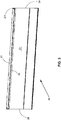
Figure 3 , the general view of the cover is given. - In
Figure 4 , the cut-out application realized on the cover is given. - In
Figure 5 , the view of the cover's cut-out part connected on the pin is given. - In this detailed explanation, the subject matter improvement is explained with references to the annexed figures without forming any restrictive effect in order to make the subject more understandable. Accordingly, in the detailed description below and in the figures, the structural members and the operation thereof are described related to the arrangement facilitating assembly in the frame of the structural changes realized on the cover (20) whose assembly is realized inside the liner (11) of the cooling device (10).
- With reference to
Figure 1 andFigure 2 , there is a cover (20) which is assembled inside the liner (11) of the cooling device (10). Inside the liner (11), there is an ice machine (12) whose assembly is realized. There is a shelf (13) which is connected inside the liner (11) so as to be adjacent to said ice machine (12). The shelf (13), which is connected so as to contact with the lower surface of the ice machine (12), defines a storage region (50) so as to be adjacent to the ice machine (12). - With reference to
Figure 3 , there is a cover (20) whereon arrangements are realized. Said cover (20) has a rectangular shape. There is a connection part (21) which is embodied on the cover (20) so as to form one of the long edges of the cover (20). The connection part (21) has a cylindrical form. There is a pin housing (211) which is embodied on the connection part (21). Said pin housing (211) is at the connection part's (21) side close to the first edge (24). At the connection part's (21) side close to the second edge (25), there is the connection region (30) where said arrangement is realized. On the inner surface (23) of the cover (20), there is a support bar (22) extending along the long edge so as to be parallel to the connection part (21). - With reference to
Figure 5 , there is a fixation member (40) which is connected to the connection surface (111) inside the cooling device (10) liner (11). The fixation member (40) comprises pluralities of items which are embodied on a rectangular plate. There are two connection openings (42) which are embodied on the body of the fixation member (40). There is one lower pin (41) and there is one upper pin (not illustrated in the figure), which are embodied so as to correspond to the end parts of the body. There is a stopper member (43) which is embodied so as to be adjacent to said upper pin. - With reference to
Figure 4 , the connection region (30) can be seen where the related arrangement is realized on the cover (20). There is a cut-out (31) which is embodied at the end region of the connection part (21). Said cut-out (31) is obtained by removing a small piece in semi-cylinder form from the end region of the connection part (21). The cut-out (31) has a cross section which is in the form of a semi-circle. There is a connection opening (35) which is embodied on the support bar (22). Said connection opening (35) is positioned in the same alignment with the cut-out (31) in the vertical direction. There is a fixation piece (32) which is connected to the support bar (22). Said fixation piece (32) is formed by the joining of a rectangular assembly part (322) and a semi-circular housing part (321). Said housing part (321) has a semi-circular cross section similar to the cut-out (31). There is a screw housing (33) on the assembly part (322) center of the fixation piece (32). Moreover, there is a screw (34) which is connected to said screw housing (33). - With reference to
Figure 1 , said cover (20) is assembled inside the liner (11) through the connection part (21). The pin housing (211) existing on the connection part (21) forms a housing for the upper pin on the fixation member (40). By means of the connection members placed to the connection openings (42) on the fixation member (40), the assembly thereof inside the liner is realized. The lower pin (41) helps the cover (20) to preserve the position thereof when in closed position. In a similar manner, the stopper member (43) helps the cover to preserve the position thereof when the cover is in open position. - With reference to
Figure 4 , the application of the arrangement regarding the assembly of the cover (20) is as follows. The screw housing (33) existing on the assembly part (322) and the connection opening (35) existing on the support bar (22) are brought one above the other so as to be concentric. After this process, a screw (34) is connected to the screw housing (33) and thus to the connection opening (35). In this manner, the fixation piece (32) is connected onto the support bar (22). After the assembly process, the cut-out (31) and the fixation piece's (32) housing part (321) are brought together. Thus, the cut-out (31), which is open and which is in semi-circular form, is partially or completely closed with the help of the housing part (321). The housing part (321) which joins with the cut-out (31) defines a new pin housing. - Under the light of the information given above, the assembly of said cover (20) inside the liner (11) is as follows. The pin housing (211) existing on the cover's (20) connection part (21) is connected with the upper pin existing on the fixation member (40). The cut-out (31) on the cover (20) is brought to the same alignment with the upper pin existing on the fixation member (40). When the upper pin is in contact with the walls of the cut-out (31), the fixation piece (32) is connected to the support bar (22). By means of this, the upper pin is restrained inside the cut-out (31). Thereby, the cover (20), which is connected to both of the upper pins, is assembled inside the liner (11). The cover (20) can move on the upper pins, it can rotate in an easy manner on the axis defined by the connection part (21). The cover (20) is positioned inside the liner (11) so as to be able to cover the ice machine (12) and so as to be able to cover the storage regions (50) embodied around the ice machine (12). By means of this, inside the liner (11) of the cooling device (10), a visual integrity is provided and at the same time, an aesthetic view is provided to the liner (11). By means of the assembly application described above, during the assembly of the covers (20) inside the liner (11), the applications like bending processes on the cover (20), which can lead to shape deteriorations, are prevented. Moreover, the assembly of the covers can be realized in a more rapid manner.
- The protection scope of the present invention is set forth in the annexed Claims and cannot be restricted to the illustrative disclosures given above, under the detailed description. It is because a person skilled in the relevant art can obviously produce similar embodiments under the light of the foregoing disclosures, without departing from the main principles of the present invention.
-
- 10 Cooling Device
- 11 Liner
- 111 Connection Surface
- 12 Ice Machine
- 13 Shelf
- 11 Liner
- 20 Cover
- 21 Connection Part
- 211 Pin Housing
- 22 Support Bar
- 23 Inner Surface
- 24 First Edge
- 25 Second Edge
- 21 Connection Part
- 30 Connection Region
- 31 Cut-out
- 32 Fixation Piece
- 321 Housing part
- 322 Assembly Part
- 33 Screw Housing
- 34 Screw
- 35 Connection Opening
- 40 Fixation Member
- 41 Lower Pin
- 42 Connection Opening
- 43 Stopper Member
- 50 Storage Region
Claims (10)
- A cooling device (10), particularly a domestic type of cooling device, comprising at least one fixation member (40) which is assembled inside the liner (11) of the cooling device (10) and which has a pin; and a cover (20) which is connected to the fixation member (40) through a connection part (21) which is in connection with said pin, characterized in that, it comprises at least one cut-out (31) embodied on said connection part (21), at least one fixation piece (32) connected to the cover (20) so as to cover said cut-out (31) at least partially so as to define a pin housing where the pin is restrained.
- A cooling device according to claim 1, wherein the cut-out (31) has a cross section similar to a semi-circle.
- A cooling device according to claim 1 or 2, wherein the cut-out (31) begins from the inlet part of the connection part (21), wherein a pin enters, and the cut-out (31) extends partially along the connection part (21).
- A cooling device according to claim 1, wherein the fixation piece (32) comprises a housing part (321) which is embodied so as to partially or completely cover the cut-out (31); and an assembly part (322) which extends at the continuation of said housing part (321).
- A cooling device according to any one of the preceding claims, wherein said housing part (321) has a cross section similar to a semi-circle so as to be compliant with the cut-out (31).
- A cooling device according to claim 1, wherein a support bar (22) is provided which extends substantially parallel to the connection part (21) at the lower alignment of the connection part (21) and whereon the fixation piece (32) is assembled.
- A cooling device according to claim 6, wherein a screw housing (33) is provided on said assembly part (322); and at least one connection opening (35) is provided on the support bar (22) so as to correspond to said screw housing (33).
- A cooling device according to any one of the preceding claims, wherein at least one screw (34) is provided which is connected to the screw housing (33) and to the connection opening (35); in order to provide the fixation member (32) to be connected to the support bar (21) through the screw housing (33).
- A cooling device according to any one of the preceding claims, wherein the cover (20) is positioned inside the liner (11) so as to be able to cover at least one ice machine (12) and so as to be able to cover at least one storage region (50) adjacent to said ice machine (12) and so as to control the access to these items (12, 50).
- A cooling device according to any one of the preceding claims, wherein said cooling device (10) is a refrigerator.
Applications Claiming Priority (1)
| Application Number | Priority Date | Filing Date | Title |
|---|---|---|---|
| TR2011/01112A TR201101112A2 (en) | 2011-02-07 | 2011-02-07 | A cooling device with lid in the bathtub |
Publications (2)
| Publication Number | Publication Date |
|---|---|
| EP2484997A2 true EP2484997A2 (en) | 2012-08-08 |
| EP2484997A3 EP2484997A3 (en) | 2018-03-21 |
Family
ID=45524374
Family Applications (1)
| Application Number | Title | Priority Date | Filing Date |
|---|---|---|---|
| EP12152273.4A Withdrawn EP2484997A3 (en) | 2011-02-07 | 2012-01-24 | A cooling device with a cover in the liner |
Country Status (2)
| Country | Link |
|---|---|
| EP (1) | EP2484997A3 (en) |
| TR (1) | TR201101112A2 (en) |
Citations (1)
| Publication number | Priority date | Publication date | Assignee | Title |
|---|---|---|---|---|
| US20030019873A1 (en) | 2001-07-28 | 2003-01-30 | Samsung Electronics Co., Ltd. | Hinge device for storage container |
Family Cites Families (5)
| Publication number | Priority date | Publication date | Assignee | Title |
|---|---|---|---|---|
| DE7431799U (en) * | 1975-01-09 | Licentia Patent Verwaltungs Gmbh | Fridge door with a freezer door | |
| DE2924989C2 (en) * | 1979-06-21 | 1982-08-26 | Bosch-Siemens Hausgeräte GmbH, 7000 Stuttgart | Refrigerated cabinets, in particular refrigerators or freezers |
| US20060226750A1 (en) * | 2005-04-08 | 2006-10-12 | Lee Jeong Y | Refrigerator having home bar |
| DE202005014371U1 (en) * | 2005-09-12 | 2005-11-17 | BSH Bosch und Siemens Hausgeräte GmbH | A method for accessing the tiered storage compartments of an upright refrigeration appliance has flaps hinged at the lower edge opening through 180 degrees |
| KR101377152B1 (en) * | 2006-08-11 | 2014-03-25 | 삼성전자주식회사 | Refrigerator |
-
2011
- 2011-02-07 TR TR2011/01112A patent/TR201101112A2/en unknown
-
2012
- 2012-01-24 EP EP12152273.4A patent/EP2484997A3/en not_active Withdrawn
Patent Citations (1)
| Publication number | Priority date | Publication date | Assignee | Title |
|---|---|---|---|---|
| US20030019873A1 (en) | 2001-07-28 | 2003-01-30 | Samsung Electronics Co., Ltd. | Hinge device for storage container |
Also Published As
| Publication number | Publication date |
|---|---|
| TR201101112A2 (en) | 2012-08-22 |
| EP2484997A3 (en) | 2018-03-21 |
Similar Documents
| Publication | Publication Date | Title |
|---|---|---|
| EP3722715B1 (en) | Drawer assembly structure and refrigerator having same | |
| EP2693295A2 (en) | Hinge device and electronic apparatus using that hinge device | |
| EP2762815B1 (en) | A home appliance comprising a transfer element between a body and a door thereof | |
| EP3121456A1 (en) | Assemblable structure | |
| DE102013211103A1 (en) | Refrigeration device with door opening help | |
| CN106839620B (en) | The door attachment device and embedded fridge device of built-in refrigerator | |
| EP2824406B1 (en) | Refrigerator | |
| EP2677258A3 (en) | Refrigerator | |
| EP3770538A1 (en) | Refrigerator | |
| EP2889566B1 (en) | Door structure for a refrigeration device | |
| US10126042B2 (en) | Cooling device comprising a support base and a support rail | |
| US9841221B2 (en) | Refrigerator | |
| US20180298657A1 (en) | Refrigerator and Hinge Device for Door of Refrigerator | |
| EP3193112A1 (en) | Refrigerator drawer and refrigerator | |
| US10434447B2 (en) | Door and door closure system for an air filter cabinet | |
| KR20070108895A (en) | Filter media retainer | |
| CN102155837A (en) | Refrigerator | |
| CN106196869A (en) | Slide mechanism of drawer and there is its refrigerator | |
| US20130104344A1 (en) | Hinge-mounted door stop | |
| EP3809548B1 (en) | Cable management assembly | |
| CN205812120U (en) | Phone housing | |
| US20160278226A1 (en) | Mounting clip for set top box enclosures | |
| EP2975346A1 (en) | Refrigerator | |
| US9932762B2 (en) | Door-equipped housing | |
| CN105551379B (en) | Display screen fixing assembly and electric cabinet |
Legal Events
| Date | Code | Title | Description |
|---|---|---|---|
| PUAI | Public reference made under article 153(3) epc to a published international application that has entered the european phase |
Free format text: ORIGINAL CODE: 0009012 |
|
| AK | Designated contracting states |
Kind code of ref document: A2 Designated state(s): AL AT BE BG CH CY CZ DE DK EE ES FI FR GB GR HR HU IE IS IT LI LT LU LV MC MK MT NL NO PL PT RO RS SE SI SK SM TR |
|
| AX | Request for extension of the european patent |
Extension state: BA ME |
|
| RIN1 | Information on inventor provided before grant (corrected) |
Inventor name: ARSLANKIRAY, ZIYA Inventor name: ENGIN, ERCAN Inventor name: HASTUERK, CEMALETTIN |
|
| RAP1 | Party data changed (applicant data changed or rights of an application transferred) |
Owner name: BSH HAUSGERAETE GMBH |
|
| PUAL | Search report despatched |
Free format text: ORIGINAL CODE: 0009013 |
|
| AK | Designated contracting states |
Kind code of ref document: A3 Designated state(s): AL AT BE BG CH CY CZ DE DK EE ES FI FR GB GR HR HU IE IS IT LI LT LU LV MC MK MT NL NO PL PT RO RS SE SI SK SM TR |
|
| AX | Request for extension of the european patent |
Extension state: BA ME |
|
| RIC1 | Information provided on ipc code assigned before grant |
Ipc: F25D 23/02 20060101ALI20180210BHEP Ipc: F25D 23/06 20060101AFI20180210BHEP |
|
| STAA | Information on the status of an ep patent application or granted ep patent |
Free format text: STATUS: THE APPLICATION IS DEEMED TO BE WITHDRAWN |
|
| 18D | Application deemed to be withdrawn |
Effective date: 20180922 |