EP2484975A2 - Turbine combustor configured for high-frequency dynamics mitigation and related method - Google Patents
Turbine combustor configured for high-frequency dynamics mitigation and related method Download PDFInfo
- Publication number
- EP2484975A2 EP2484975A2 EP11191209A EP11191209A EP2484975A2 EP 2484975 A2 EP2484975 A2 EP 2484975A2 EP 11191209 A EP11191209 A EP 11191209A EP 11191209 A EP11191209 A EP 11191209A EP 2484975 A2 EP2484975 A2 EP 2484975A2
- Authority
- EP
- European Patent Office
- Prior art keywords
- micro
- nozzle
- mixer
- axial length
- nozzles
- Prior art date
- Legal status (The legal status is an assumption and is not a legal conclusion. Google has not performed a legal analysis and makes no representation as to the accuracy of the status listed.)
- Granted
Links
Images

Classifications
-
- F—MECHANICAL ENGINEERING; LIGHTING; HEATING; WEAPONS; BLASTING
- F23—COMBUSTION APPARATUS; COMBUSTION PROCESSES
- F23D—BURNERS
- F23D14/00—Burners for combustion of a gas, e.g. of a gas stored under pressure as a liquid
- F23D14/46—Details
- F23D14/62—Mixing devices; Mixing tubes
-
- F—MECHANICAL ENGINEERING; LIGHTING; HEATING; WEAPONS; BLASTING
- F23—COMBUSTION APPARATUS; COMBUSTION PROCESSES
- F23M—CASINGS, LININGS, WALLS OR DOORS SPECIALLY ADAPTED FOR COMBUSTION CHAMBERS, e.g. FIREBRIDGES; DEVICES FOR DEFLECTING AIR, FLAMES OR COMBUSTION PRODUCTS IN COMBUSTION CHAMBERS; SAFETY ARRANGEMENTS SPECIALLY ADAPTED FOR COMBUSTION APPARATUS; DETAILS OF COMBUSTION CHAMBERS, NOT OTHERWISE PROVIDED FOR
- F23M20/00—Details of combustion chambers, not otherwise provided for, e.g. means for storing heat from flames
- F23M20/005—Noise absorbing means
-
- F—MECHANICAL ENGINEERING; LIGHTING; HEATING; WEAPONS; BLASTING
- F23—COMBUSTION APPARATUS; COMBUSTION PROCESSES
- F23R—GENERATING COMBUSTION PRODUCTS OF HIGH PRESSURE OR HIGH VELOCITY, e.g. GAS-TURBINE COMBUSTION CHAMBERS
- F23R3/00—Continuous combustion chambers using liquid or gaseous fuel
- F23R3/02—Continuous combustion chambers using liquid or gaseous fuel characterised by the air-flow or gas-flow configuration
- F23R3/04—Air inlet arrangements
- F23R3/10—Air inlet arrangements for primary air
-
- F—MECHANICAL ENGINEERING; LIGHTING; HEATING; WEAPONS; BLASTING
- F23—COMBUSTION APPARATUS; COMBUSTION PROCESSES
- F23R—GENERATING COMBUSTION PRODUCTS OF HIGH PRESSURE OR HIGH VELOCITY, e.g. GAS-TURBINE COMBUSTION CHAMBERS
- F23R3/00—Continuous combustion chambers using liquid or gaseous fuel
- F23R3/28—Continuous combustion chambers using liquid or gaseous fuel characterised by the fuel supply
- F23R3/286—Continuous combustion chambers using liquid or gaseous fuel characterised by the fuel supply having fuel-air premixing devices
-
- F—MECHANICAL ENGINEERING; LIGHTING; HEATING; WEAPONS; BLASTING
- F23—COMBUSTION APPARATUS; COMBUSTION PROCESSES
- F23R—GENERATING COMBUSTION PRODUCTS OF HIGH PRESSURE OR HIGH VELOCITY, e.g. GAS-TURBINE COMBUSTION CHAMBERS
- F23R2900/00—Special features of, or arrangements for continuous combustion chambers; Combustion processes therefor
- F23R2900/00002—Gas turbine combustors adapted for fuels having low heating value [LHV]
-
- F—MECHANICAL ENGINEERING; LIGHTING; HEATING; WEAPONS; BLASTING
- F23—COMBUSTION APPARATUS; COMBUSTION PROCESSES
- F23R—GENERATING COMBUSTION PRODUCTS OF HIGH PRESSURE OR HIGH VELOCITY, e.g. GAS-TURBINE COMBUSTION CHAMBERS
- F23R2900/00—Special features of, or arrangements for continuous combustion chambers; Combustion processes therefor
- F23R2900/00014—Reducing thermo-acoustic vibrations by passive means, e.g. by Helmholtz resonators
Definitions
- This invention relates generally to gas turbine combustion technology and, more specifically, to a fuel injection micro-mixer nozzle arrangement designed for high concentration of hydrogen fuel combustion and high frequency-dynamic-tone mitigation.
- Combustion instability/dynamics is a phenomenon in turbomachines utilizing lean pre-mixed combustion.
- combustion instability can be caused by high or low frequency dynamic fields.
- a low frequency combustion dynamics field is typically caused by excitation of axial modes, whereas a high frequency dynamic field is generally caused by the excitation of radial, azimuthal and axial modes by the combustion process, commonly referred to as "screech".
- the high-frequency dynamic field includes all combustor components that are involved in combustion. Under certain operating conditions, the combustion component and the acoustic component couple to create a high and/or low frequency dynamic field that has a negative impact on various turbomachine components with a potential for hardware damage.
- the dynamic field passing from the combustor may also excite modes of downstream turbomachine components that can lead to damage to those parts.
- turbomachines may be operated at less than optimum levels, i.e., certain operating conditions are avoided in order to avoid circumstances that are conducive to combustion instability. While effective at suppressing combustion instability, avoiding these operating conditions restricts the overall operating envelope of the turbomachine.
- Another approach to the problem of combustion instability is to modify combustor input conditions. More specifically, fluctuations in the fuel-air ratio are known to cause combustion dynamics that lead to combustion instability. Creating perturbations in the fuel-air mixture by changing fuel flow rate can disengage the combustion field from the acoustic field to suppress combustion instability.
- the present invention resides in a turbomachine combustor comprising a combustion chamber; a plurality of micro-mixer nozzles mounted to an end cover of the combustion chamber, each micro-mixer nozzle including a fuel supply pipe affixed to a nozzle body located within the combustion chamber, each nozzle body comprising a substantially hollow body formed with an upstream end face, a downstream end face and a peripheral wall extending therebetween, wherein each substantially hollow body is provided with a plurality of pre-mix tubes or passages extending axially through the substantially hollow body, thereby permitting fuel from the supply pipe to mix with air in the nozzle body prior to discharge into the combustion chamber; and wherein at least some nozzle bodies of the plurality of micro-mixer nozzles have axial length dimensions that differ from axial length dimensions of other of the nozzle bodies.
- the invention resides in a method of mitigating high frequency dynamics in a turbine combustor incorporating plural micro-mixer nozzles arranged substantially in parallel, each micro-mixer nozzle having a nozzle body at an aft end thereof, the method comprising arranging the plural micro-mixer nozzles in an array of radially outer micro-mixer nozzles surrounding a center micro-mixer nozzle; each of the radially outer micro-mixer nozzle bodies and the center micro-mixer nozzle body comprising a substantially hollow body formed with an upstream end face, a downstream end face and a peripheral wall extending therebetween, , with a plurality of pre-mix tubes or passages extending axially through the substantially hollow body; and forming at least some of the plural micro-mixer nozzles to have nozzle bodies of respectively different axial length dimensions.
- a gas turbine combustor 10 includes an end cover 12 that supports a plurality of micro-mixer fuel injection nozzles 14 extending through a chamber 16 between the end cover 12 and an aft cap assembly 18.
- a flow sleeve 20 surrounds the combustor liner 22 and provides a path for compressor air to flow in a direction opposite the flow of combustion gases through the combustor.
- the air supplied by the compressor is also used to cool the transition piece 24 (not shown) which supplies the hot combustion gases to the turbine first stage (not shown) adjacent the outlet end of the transition piece.
- Fuel is supplied through the plumbed pipes 24, the end cover 12 and through the nozzle pipes 26 to the micro-mixer nozzle bodies 28 where the fuel mixes with air as described further herein, and is then injected into the combustion chamber 30 where the fuel is burned and then supplied in gaseous form to the turbine first stage via the transition piece.
- the nozzle bodies 28 are also supported at their aft ends by the aft cap assembly 18.
- plural combustors 10 are typically arranged to supply a mixture of fuel and air to the respective combustion chambers.
- an annular array of such combustors (often referred to as a "can-annular" array) supply combustion gases to a first stage of the turbine by means of a like number of transition pieces or ducts.
- the micro-mixer nozzle bodies 28 each may be formed as a substantially hollow, cylindrical body 32 A, B or C, each having an upstream end face 34 and an aft or downstream end face 36, substantially parallel to one another, with an annular peripheral wall 38 axially therebetween.
- Internal air supply passages or tubes 40 also referred to as pre-mix tubes
- the inlets may be flared outwardly (i.e., formed with a bell-mouth shape) to facilitate (and accelerate) the flow of air into and through the tubes.
- the pre-mix tubes 40 may be arranged in annular, concentric rows, with the pre-mix tubes of any given row circumferentially offset from the pre-mix tubes or passages of an adjacent row. It will be appreciated, however, that the invention is not limited by any specific arrangement of pre-mix tubes 40 within the hollow body 32.
- the center region of the hollow body 32 is open at the forward or upstream end face, providing an inlet for receiving the fuel feed tube or pipe 26, such that fuel is supplied to the hollow body interior space surrounding the pre-mix tubes 40.
- At least one, and preferably an array of fuel injection holes is provided in each of the pre-mix tubes 40, e.g., four in each tube, at equally-spaced locations about the circumference of the respective tube.
- the fuel injection holes may be slanted in the direction of flow, i.e., the holes may be angled radially inwardly (at low acute angles, for example 30°, relative to the centerline of the respective pre-mix tube 40) in the downstream direction so that the flow of fuel through the injection holes has a velocity component in the direction of the air flowing through the pre-mix tubes 40.
- the injection holes 42 may extend at any angle between 15° and substantially 90° relative to the longitudinal axes of the pre-mix tubes. Additional details relating to the nozzle construction may be found in, for example, commonly-owned U.S. Published Application No. US2010/0218510 A1 .
- the high-hydrogen fuel will flow through the fuel injection holes 42 and into the pre-mix tubes 40 where the fuel and air mix before exiting the nozzle body 32 at the aft end face 36 into the combustion chamber 30.
- micro-mixers nozzle bodies 32 it has been determined that high frequency-dynamic-tone or high screech mitigation can be achieved by changing the axial length dimension of the micro-mixers nozzle bodies 32.
- an annular array of six micro-mixer nozzle bodies surround a center micro-mixer nozzle body. All of the micro-mixer nozzle bodies 32 are aligned substantially in the same plane at their respective outlet ends, best seen in Figs. 1 and 3 and consistent with the nozzle body orientation in Fig. 1 , with cap assembly 18 substantially defining the singe plane.
- the inlet ends to the nozzle bodies do not lie in a single plane, and it is here that the differential length dimensions are implemented.
- the micro-mixer nozzle bodies 32A, 32B and 32C are assigned certain locations in the radially outer array and in the center of the array.
- nozzle body 32A may be used in the center, at location A; and nozzle bodies 32B and 32C may be used in various combinations at the radially outer nozzle locations B-G.
- nozzle bodies 32B and 32C may be arranged in alternating fashion. While three differential length bodies 32A, 32B and 32C are illustrated, it will be appreciated that the six nozzle bodies in the outer array may have six different axial lengths, and the center nozzle body may have one of those six axial lengths or a different, seventh axial length, shorter or longer than the outer nozzle bodies.
- any combination of different lengths may be employed, but it is important to avoid certain relative length relationships, specifically, lengths that are 1 ⁇ 2 or 2x another length. This is because at 1 ⁇ 2 or 2x length, vibrations will occur in harmonics and sub-harmonics of fundamental waves, respectively, with little or no screech mitigation. It is also preferable that any two adjacent outer nozzle bodies not have the same length.
- FIG. 4 alternative micro-mixer nozzle bodies 32H and 32I are illustrated where stepped configurations at the forward ends of the nozzle bodies are provided.
- Nozzle body 32H is formed with a step or shoulder 44 on the upstream side such that a first aft portion 46 of the nozzle body has an outer diameter greater than a forward portion 48, such that the axial length of the premix tubes 40 in the aft or radially outer portion 46 of the nozzle body is less than the axial length of the premix tubes in the forward or radially inner portion 48 of the nozzle body.
- the nozzle body 32H has differential length dimensions integrated therein. It will be appreciated that multiple steps or shoulders may be incorporated into the upstream end of the nozzle body.
- Nozzle body 32I is reversed relative to nozzle body 32H in that the axial length of the radially outer portion 50 is greater than the radially inner portion 52 such that pre-mix tubes in the radially outer portion 50 have axial length dimensions greater than axial lengths of pre-mix tubes in the radially inner portion 52.
- multiple steps or shoulders may be incorporated into the upstream end of the nozzle body, and multiple combinations of the nozzle bodies 32D and E are possible.
- nozzle bodies 32D and/or 32E may be used with one or more of nozzle bodies 32A-C consistent with the caveats noted above.
- FIG. 5 is a schematic aft-end view of an alternative configuration for micro-mixer nozzles to which the invention described herein is applicable.
- the nozzle bodies 54 at locations B-G are "sector-shaped", while the center nozzle body 56 at location A remains round as in Figs. 1-4 .
- the differentiated lengths as described in connection with Figs. 3 and 4 are fully applicable to the sector-shaped nozzle bodies. It will be appreciated that the other nozzle body shapes may be employed as well.
Landscapes
- Engineering & Computer Science (AREA)
- Chemical & Material Sciences (AREA)
- Combustion & Propulsion (AREA)
- Mechanical Engineering (AREA)
- General Engineering & Computer Science (AREA)
- Gas Burners (AREA)
Abstract
Description
- This invention relates generally to gas turbine combustion technology and, more specifically, to a fuel injection micro-mixer nozzle arrangement designed for high concentration of hydrogen fuel combustion and high frequency-dynamic-tone mitigation.
- Combustion instability/dynamics is a phenomenon in turbomachines utilizing lean pre-mixed combustion. Depending on the nature of the excitation of combustion chamber modes, combustion instability can be caused by high or low frequency dynamic fields. A low frequency combustion dynamics field is typically caused by excitation of axial modes, whereas a high frequency dynamic field is generally caused by the excitation of radial, azimuthal and axial modes by the combustion process, commonly referred to as "screech". The high-frequency dynamic field includes all combustor components that are involved in combustion. Under certain operating conditions, the combustion component and the acoustic component couple to create a high and/or low frequency dynamic field that has a negative impact on various turbomachine components with a potential for hardware damage. The dynamic field passing from the combustor may also excite modes of downstream turbomachine components that can lead to damage to those parts.
- It is known, for example, that high hydrogen and nitrogen in the gas turbine fuel with certain fuel/air ratios from the fuel nozzles can lead to high-amplitude screech tone dynamics greater than 1.0 kHz in frequency. This kind of high frequency tone can transfer strong vibrational energy to combustor components that can result in hardware damage.
- To address this problem, turbomachines may be operated at less than optimum levels, i.e., certain operating conditions are avoided in order to avoid circumstances that are conducive to combustion instability. While effective at suppressing combustion instability, avoiding these operating conditions restricts the overall operating envelope of the turbomachine.
- Another approach to the problem of combustion instability is to modify combustor input conditions. More specifically, fluctuations in the fuel-air ratio are known to cause combustion dynamics that lead to combustion instability. Creating perturbations in the fuel-air mixture by changing fuel flow rate can disengage the combustion field from the acoustic field to suppress combustion instability.
- While both of the above approaches are effective at suppressing combustion instability, avoiding various operating conditions restricts an overall operating envelope of the turbomachine, and manipulating the fuel-air ratio requires a complex control scheme, and may lead to less than efficient combustion.
- According to a first aspect, the present invention resides in a turbomachine combustor comprising a combustion chamber; a plurality of micro-mixer nozzles mounted to an end cover of the combustion chamber, each micro-mixer nozzle including a fuel supply pipe affixed to a nozzle body located within the combustion chamber, each nozzle body comprising a substantially hollow body formed with an upstream end face, a downstream end face and a peripheral wall extending therebetween, wherein each substantially hollow body is provided with a plurality of pre-mix tubes or passages extending axially through the substantially hollow body, thereby permitting fuel from the supply pipe to mix with air in the nozzle body prior to discharge into the combustion chamber; and wherein at least some nozzle bodies of the plurality of micro-mixer nozzles have axial length dimensions that differ from axial length dimensions of other of the nozzle bodies.
- In still another aspect, the invention resides in a method of mitigating high frequency dynamics in a turbine combustor incorporating plural micro-mixer nozzles arranged substantially in parallel, each micro-mixer nozzle having a nozzle body at an aft end thereof, the method comprising arranging the plural micro-mixer nozzles in an array of radially outer micro-mixer nozzles surrounding a center micro-mixer nozzle; each of the radially outer micro-mixer nozzle bodies and the center micro-mixer nozzle body comprising a substantially hollow body formed with an upstream end face, a downstream end face and a peripheral wall extending therebetween, , with a plurality of pre-mix tubes or passages extending axially through the substantially hollow body; and forming at least some of the plural micro-mixer nozzles to have nozzle bodies of respectively different axial length dimensions.
- Embodiments of the invention will now be described, by way of example only, with reference to the accompanying drawings in which:
-
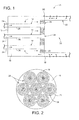
Fig. 1 is a partial, simplified schematic view of a combustor incorporating a plurality of micro-mixer nozzles in accordance with a first exemplary but nonlimiting embodiment; -
Fig. 2 is a schematic aft-end view of the micro-mixer nozzles in the combustor ofFig. 1 ; -
Fig. 3 is a partial side profile of the micro-mixer nozzle bodies utilized in the combustor ofFig. 1 , illustrating exemplary differential lengths of the nozzle bodies; -
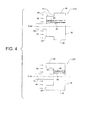
Fig. 4 is a partial side profile of micro-mixer nozzle body configurations in accordance with other exemplary but nonlimiting embodiments; and -
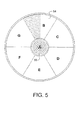
Fig. 5 is a schematic aft-end view of an alternative configuration for micro-mixer nozzles to which the invention described herein is applicable. - With reference to
Fig. 1 , agas turbine combustor 10 includes anend cover 12 that supports a plurality of micro-mixerfuel injection nozzles 14 extending through achamber 16 between theend cover 12 and anaft cap assembly 18. Aflow sleeve 20 surrounds thecombustor liner 22 and provides a path for compressor air to flow in a direction opposite the flow of combustion gases through the combustor. The air supplied by the compressor is also used to cool the transition piece 24 (not shown) which supplies the hot combustion gases to the turbine first stage (not shown) adjacent the outlet end of the transition piece. - Fuel is supplied through the
plumbed pipes 24, theend cover 12 and through thenozzle pipes 26 to themicro-mixer nozzle bodies 28 where the fuel mixes with air as described further herein, and is then injected into thecombustion chamber 30 where the fuel is burned and then supplied in gaseous form to the turbine first stage via the transition piece. Thenozzle bodies 28 are also supported at their aft ends by theaft cap assembly 18. - It will be appreciated that
plural combustors 10 are typically arranged to supply a mixture of fuel and air to the respective combustion chambers. In a known turbine configuration, an annular array of such combustors (often referred to as a "can-annular" array) supply combustion gases to a first stage of the turbine by means of a like number of transition pieces or ducts. - With reference now also to
Figs. 2 and3 , themicro-mixer nozzle bodies 28 each may be formed as a substantially hollow,cylindrical body 32 A, B or C, each having anupstream end face 34 and an aft ordownstream end face 36, substantially parallel to one another, with an annularperipheral wall 38 axially therebetween. Internal air supply passages or tubes 40 (also referred to as pre-mix tubes) extend between the upstream anddownstream end faces pre-mix tubes 40 may be arranged in annular, concentric rows, with the pre-mix tubes of any given row circumferentially offset from the pre-mix tubes or passages of an adjacent row. It will be appreciated, however, that the invention is not limited by any specific arrangement ofpre-mix tubes 40 within thehollow body 32. - The center region of the
hollow body 32 is open at the forward or upstream end face, providing an inlet for receiving the fuel feed tube orpipe 26, such that fuel is supplied to the hollow body interior space surrounding thepre-mix tubes 40. - At least one, and preferably an array of fuel injection holes (schematically shown in
Figs. 3 and4 at 42) is provided in each of thepre-mix tubes 40, e.g., four in each tube, at equally-spaced locations about the circumference of the respective tube. The fuel injection holes may be slanted in the direction of flow, i.e., the holes may be angled radially inwardly (at low acute angles, for example 30°, relative to the centerline of the respective pre-mix tube 40) in the downstream direction so that the flow of fuel through the injection holes has a velocity component in the direction of the air flowing through thepre-mix tubes 40. It will be understood, however, that theinjection holes 42 may extend at any angle between 15° and substantially 90° relative to the longitudinal axes of the pre-mix tubes. Additional details relating to the nozzle construction may be found in, for example, commonly-owned U.S. Published Application No.US2010/0218510 A1 . - The high-hydrogen fuel will flow through the
fuel injection holes 42 and into thepre-mix tubes 40 where the fuel and air mix before exiting thenozzle body 32 at theaft end face 36 into thecombustion chamber 30. - In accordance with an exemplary but nonlimiting embodiment, it has been determined that high frequency-dynamic-tone or high screech mitigation can be achieved by changing the axial length dimension of the
micro-mixers nozzle bodies 32. Specifically, in one exemplary but nonlimiting embodiment (Figs. 1-3 ), an annular array of six micro-mixer nozzle bodies surround a center micro-mixer nozzle body. All of themicro-mixer nozzle bodies 32 are aligned substantially in the same plane at their respective outlet ends, best seen inFigs. 1 and3 and consistent with the nozzle body orientation inFig. 1 , withcap assembly 18 substantially defining the singe plane. The inlet ends to the nozzle bodies, however, do not lie in a single plane, and it is here that the differential length dimensions are implemented. InFig. 2 , themicro-mixer nozzle bodies nozzle body 32A may be used in the center, at location A; andnozzle bodies nozzle bodies differential length bodies - Essentially, any combination of different lengths may be employed, but it is important to avoid certain relative length relationships, specifically, lengths that are ½ or 2x another length. This is because at ½ or 2x length, vibrations will occur in harmonics and sub-harmonics of fundamental waves, respectively, with little or no screech mitigation. It is also preferable that any two adjacent outer nozzle bodies not have the same length.
- Turning to
Fig. 4 , alternative micro-mixer nozzle bodies 32H and 32I are illustrated where stepped configurations at the forward ends of the nozzle bodies are provided. Nozzle body 32H is formed with a step orshoulder 44 on the upstream side such that afirst aft portion 46 of the nozzle body has an outer diameter greater than aforward portion 48, such that the axial length of thepremix tubes 40 in the aft or radiallyouter portion 46 of the nozzle body is less than the axial length of the premix tubes in the forward or radiallyinner portion 48 of the nozzle body. Stated otherwise, the nozzle body 32H has differential length dimensions integrated therein. It will be appreciated that multiple steps or shoulders may be incorporated into the upstream end of the nozzle body. - Nozzle body 32I is reversed relative to nozzle body 32H in that the axial length of the radially
outer portion 50 is greater than the radiallyinner portion 52 such that pre-mix tubes in the radiallyouter portion 50 have axial length dimensions greater than axial lengths of pre-mix tubes in the radiallyinner portion 52. Here again, multiple steps or shoulders may be incorporated into the upstream end of the nozzle body, and multiple combinations of thenozzle bodies 32D and E are possible. For example,nozzle bodies 32D and/or 32E may be used with one or more ofnozzle bodies 32A-C consistent with the caveats noted above. - It will be appreciated that other micro-mixer nozzle body designs that incorporate differential axial length dimensions or patterns are within the scope of the invention. For example,
Fig. 5 is a schematic aft-end view of an alternative configuration for micro-mixer nozzles to which the invention described herein is applicable. Here, thenozzle bodies 54 at locations B-G are "sector-shaped", while thecenter nozzle body 56 at location A remains round as inFigs. 1-4 . Otherwise, the differentiated lengths as described in connection withFigs. 3 and4 are fully applicable to the sector-shaped nozzle bodies. It will be appreciated that the other nozzle body shapes may be employed as well. - While the invention has been described in connection with what is presently considered to be the most practical and preferred embodiment, it is to be understood that the invention is not to be limited to the disclosed embodiment, but on the contrary, is intended to cover various modifications and equivalent arrangements.
Claims (15)
- A turbomachine combustor (10) comprising:a combustion chamber (30);a plurality of micro-mixer nozzles (14) mounted to an end cover (12) of the combustion chamber, each micro-mixer nozzle including a fuel supply pipe (26) affixed to a nozzle body (28) located within the combustion chamber, each nozzle body comprising a substantially hollow body formed with an upstream end face (34), a downstream end face (36) and a peripheral wall (38) extending therebetween, wherein each substantially hollow body is provided with a plurality of pre-mix tubes or passages (40) extending axially through said substantially hollow body, thereby permitting fuel from the supply pipe to mix with air in said nozzle body prior to discharge into said combustion chamber; andwherein at least some nozzle bodies (28) of said plurality of micro-mixer nozzles (14) have axial length dimensions that differ from axial length dimensions of other of said nozzle bodies.
- The turbomachine combustor of claim 1, wherein said plurality of micro-mixer nozzles comprise a center nozzle (32A) and an annular array of radially outer nozzles (32B-G) surrounding said center nozzle.
- The turbomachine combustor of claim 2, wherein every other nozzle body of said annular array of radially outer nozzles (32B-G) has a first axial length dimension, and wherein remaining nozzle bodies of said annular array of said radially outer nozzles have a second axial length dimension greater or less than said first axial length dimension.
- The turbomachine combustor of claim 2 or 3, wherein the nozzle body (28) of said center nozzle (32A) has an axial length dimension equal to, or different than said first and second axial length dimensions.
- The turbomachine combustor of claim 1, wherein none of said axial length dimensions of said plurality of micro-mixer nozzle bodies (28) are the same.
- The turbomachine of any preceding claim, wherein said nozzle body of one or more of said plurality of micro-mixer nozzles is formed to include a radially outer portion (46) of a first diameter, and at least one radially inner portion (48) of a second diameter less than said first diameter, connected by a radially-oriented shoulder (44), and wherein said radially outer and radially inner portions have differential axial lengths.
- The turbomachine of claim 6, wherein pre-mix tubes (40) in said radially outer portion (46) have axial length dimensions less than axial length dimensions of premix tubes in said at least one radially inner portion (48).
- The turbomachine of claim 6, wherein pre-mix tubes (40) in said radially outer portion (50) have axial length dimensions greater than axial length dimensions of premix tubes said at least one radially inner portion (52).
- A method of mitigating high frequency dynamics in a turbine combustor (10) incorporating plural micro-mixer nozzles (14) arranged substantially in parallel, each micro-mixer nozzle having a nozzle body (28) at an aft end thereof, the method comprising:a. arranging said plural micro-mixer nozzles in an array of radially outer micro-mixer nozzle bodies (32B-G) surrounding a center micro-mixer nozzle body (32A), each of said radially outer micro-mixer nozzle bodies and said center micro-mixer nozzle body comprising a substantially hollow body formed with an upstream end face (34), a downstream end face (36) and a peripheral wall (38) extending therebetween, with a plurality of pre-mix tubes or passages (40) extending axially through said substantially hollow body; andb. forming at least some of said plural micro-mixer nozzles (14) to have nozzle bodies (28) of respectively different axial length dimensions.
- The method of claim 9, wherein step b. includes forming every other nozzle body of said array of radially outer micro-mixer nozzles (32B-G) to have a first axial length dimension, and forming remaining nozzle bodies of said array of radially outer micro-mixer nozzles to have a second axial length dimension greater to or less than said first axial length dimension.
- The method of claim 10, wherein step b. further includes forming said center nozzle (32A) to have a nozzle body with a third axial length dimension different from first and second axial length dimensions.
- The method of claim 9, wherein axial length dimensions differ for each of said plurality of micro-mixer nozzles.
- The method of claim 12, wherein said nozzle body of one or more of said plurality of micro-mixer nozzles is formed to include at least first and second axially-extending portions (46,48) connected by a shoulder (44), such that said at least first and second axially-extending portions have differential axial lengths.
- The method of claim 9, wherein no adjacent nozzle bodies (28) of said plurality of nozzle bodies have identical axial lengths.
- The method of any preceding claim, wherein each radially outer micro-mixer nozzle body (54) in said array of radially outer micro-mixer nozzle bodies is sector-shaped, and said center micro-mixer nozzle body (56) is round.
Applications Claiming Priority (1)
| Application Number | Priority Date | Filing Date | Title |
|---|---|---|---|
| US13/021,298 US8875516B2 (en) | 2011-02-04 | 2011-02-04 | Turbine combustor configured for high-frequency dynamics mitigation and related method |
Publications (3)
| Publication Number | Publication Date |
|---|---|
| EP2484975A2 true EP2484975A2 (en) | 2012-08-08 |
| EP2484975A3 EP2484975A3 (en) | 2017-11-29 |
| EP2484975B1 EP2484975B1 (en) | 2020-08-05 |
Family
ID=45047654
Family Applications (1)
| Application Number | Title | Priority Date | Filing Date |
|---|---|---|---|
| EP11191209.3A Active EP2484975B1 (en) | 2011-02-04 | 2011-11-29 | Turbine combustor configured for high-frequency dynamics mitigation and related method |
Country Status (3)
| Country | Link |
|---|---|
| US (1) | US8875516B2 (en) |
| EP (1) | EP2484975B1 (en) |
| CN (1) | CN102628592B (en) |
Cited By (3)
| Publication number | Priority date | Publication date | Assignee | Title |
|---|---|---|---|---|
| CN114294680A (en) * | 2021-12-29 | 2022-04-08 | 哈尔滨工业大学 | Micro-premix combustion chamber of center-staged gas turbine |
| KR102415892B1 (en) * | 2021-01-27 | 2022-06-30 | 두산에너빌리티 주식회사 | Micromixer and combustor having the same |
| KR102429075B1 (en) * | 2021-02-17 | 2022-08-03 | 두산에너빌리티 주식회사 | Micromixer bundle assembly, combustor and gas turbin comprising it |
Families Citing this family (29)
| Publication number | Priority date | Publication date | Assignee | Title |
|---|---|---|---|---|
| US8438851B1 (en) * | 2012-01-03 | 2013-05-14 | General Electric Company | Combustor assembly for use in a turbine engine and methods of assembling same |
| US9032704B2 (en) * | 2012-08-21 | 2015-05-19 | General Electric Company | System for reducing combustion dynamics |
| US9360220B2 (en) | 2012-11-06 | 2016-06-07 | General Electric Company | Micro-mixer nozzle |
| US9599343B2 (en) | 2012-11-28 | 2017-03-21 | General Electric Company | Fuel nozzle for use in a turbine engine and method of assembly |
| US9677766B2 (en) | 2012-11-28 | 2017-06-13 | General Electric Company | Fuel nozzle for use in a turbine engine and method of assembly |
| US9435539B2 (en) | 2013-02-06 | 2016-09-06 | General Electric Company | Variable volume combustor with pre-nozzle fuel injection system |
| US9441544B2 (en) | 2013-02-06 | 2016-09-13 | General Electric Company | Variable volume combustor with nested fuel manifold system |
| US9689572B2 (en) | 2013-02-06 | 2017-06-27 | General Electric Company | Variable volume combustor with a conical liner support |
| US9546598B2 (en) | 2013-02-06 | 2017-01-17 | General Electric Company | Variable volume combustor |
| US20140216038A1 (en) * | 2013-02-06 | 2014-08-07 | General Electric Company | Variable Volume Combustor with Cantilevered Support Structure |
| US9587562B2 (en) | 2013-02-06 | 2017-03-07 | General Electric Company | Variable volume combustor with aerodynamic support struts |
| US9447975B2 (en) | 2013-02-06 | 2016-09-20 | General Electric Company | Variable volume combustor with aerodynamic fuel flanges for nozzle mounting |
| US9562687B2 (en) * | 2013-02-06 | 2017-02-07 | General Electric Company | Variable volume combustor with an air bypass system |
| US9422867B2 (en) | 2013-02-06 | 2016-08-23 | General Electric Company | Variable volume combustor with center hub fuel staging |
| KR101838822B1 (en) * | 2013-10-18 | 2018-03-14 | 미츠비시 쥬고교 가부시키가이샤 | Fuel injector |
| US11525578B2 (en) | 2017-08-16 | 2022-12-13 | General Electric Company | Dynamics-mitigating adapter for bundled tube fuel nozzle |
| CN107975822B (en) * | 2017-12-19 | 2023-03-14 | 中国科学院工程热物理研究所 | Combustion chamber of gas turbine and gas turbine using combustion chamber |
| US12553385B2 (en) | 2020-03-30 | 2026-02-17 | Ge Vernova Infrastructure Technology Llc | Compact turbomachine combustor |
| DE102020117692B4 (en) * | 2020-07-06 | 2023-06-07 | Viessmann Climate Solutions Se | Gas burner device and method for operating a gas burner device |
| KR102433673B1 (en) * | 2021-01-11 | 2022-08-18 | 두산에너빌리티 주식회사 | Fuel nozzle, fuel nozzle module and combustor having the same |
| KR102667812B1 (en) | 2022-02-07 | 2024-05-20 | 두산에너빌리티 주식회사 | Combustor with cluster and gas turbine including same |
| CN115875693B (en) * | 2022-11-03 | 2024-05-10 | 中国科学院工程热物理研究所 | Gas turbine head integrated combustion chamber and gas turbine power generation system |
| CN116398900A (en) * | 2023-04-11 | 2023-07-07 | 北京航空航天大学 | An Alternately Arranged Micro-mixing Nozzle Structure and Combustion Chamber |
| CN116447044B (en) * | 2023-06-05 | 2023-09-22 | 北京航空航天大学 | A micro-mixing nozzle structure and combustion chamber with alternate outlet diameters |
| US12379107B2 (en) | 2023-12-01 | 2025-08-05 | Doosan Enerbility Co., Ltd. | Combustor nozzle, combustor and gas turbine including same |
| US12339007B2 (en) | 2023-12-01 | 2025-06-24 | Doosan Enerbility Co., Ltd. | Combustor nozzle, combustor and gas turbine including same |
| US12339006B1 (en) | 2023-12-22 | 2025-06-24 | General Electric Company | Turbine engine having a combustion section with a fuel nozzle assembly |
| US12281795B1 (en) * | 2024-03-11 | 2025-04-22 | Rtx Corporation | Cluster of swirled mini-mixers for fuel-staged, axially staged combustion |
| US12535216B1 (en) | 2025-01-02 | 2026-01-27 | General Electric Company | Combustion section for a turbine engine |
Citations (1)
| Publication number | Priority date | Publication date | Assignee | Title |
|---|---|---|---|---|
| US20100218510A1 (en) | 2006-02-15 | 2010-09-02 | Lg Electronics Inc. | Apparatus for supercooling and method of making slush through supercooling |
Family Cites Families (42)
| Publication number | Priority date | Publication date | Assignee | Title |
|---|---|---|---|---|
| US3041836A (en) * | 1959-09-11 | 1962-07-03 | Gen Electric | Means for eliminating screech in jet propulsion systems |
| US4100733A (en) | 1976-10-04 | 1978-07-18 | United Technologies Corporation | Premix combustor |
| US4262482A (en) | 1977-11-17 | 1981-04-21 | Roffe Gerald A | Apparatus for the premixed gas phase combustion of liquid fuels |
| US4845952A (en) | 1987-10-23 | 1989-07-11 | General Electric Company | Multiple venturi tube gas fuel injector for catalytic combustor |
| US4966001A (en) | 1987-10-23 | 1990-10-30 | General Electric Company | Multiple venturi tube gas fuel injector for catalytic combustor |
| US5235814A (en) | 1991-08-01 | 1993-08-17 | General Electric Company | Flashback resistant fuel staged premixed combustor |
| US5263325A (en) | 1991-12-16 | 1993-11-23 | United Technologies Corporation | Low NOx combustion |
| US5361586A (en) * | 1993-04-15 | 1994-11-08 | Westinghouse Electric Corporation | Gas turbine ultra low NOx combustor |
| US5943866A (en) | 1994-10-03 | 1999-08-31 | General Electric Company | Dynamically uncoupled low NOx combustor having multiple premixers with axial staging |
| US5927076A (en) | 1996-10-22 | 1999-07-27 | Westinghouse Electric Corporation | Multiple venturi ultra-low nox combustor |
| SE9802707L (en) * | 1998-08-11 | 2000-02-12 | Abb Ab | Burner chamber device and method for reducing the influence of acoustic pressure fluctuations in a burner chamber device |
| US6357237B1 (en) | 1998-10-09 | 2002-03-19 | General Electric Company | Fuel injection assembly for gas turbine engine combustor |
| US6536216B2 (en) | 2000-12-08 | 2003-03-25 | General Electric Company | Apparatus for injecting fuel into gas turbine engines |
| US6813889B2 (en) * | 2001-08-29 | 2004-11-09 | Hitachi, Ltd. | Gas turbine combustor and operating method thereof |
| US6962055B2 (en) | 2002-09-27 | 2005-11-08 | United Technologies Corporation | Multi-point staging strategy for low emission and stable combustion |
| US6931853B2 (en) * | 2002-11-19 | 2005-08-23 | Siemens Westinghouse Power Corporation | Gas turbine combustor having staged burners with dissimilar mixing passage geometries |
| US7017329B2 (en) | 2003-10-10 | 2006-03-28 | United Technologies Corporation | Method and apparatus for mixing substances |
| US6993916B2 (en) * | 2004-06-08 | 2006-02-07 | General Electric Company | Burner tube and method for mixing air and gas in a gas turbine engine |
| US7003958B2 (en) | 2004-06-30 | 2006-02-28 | General Electric Company | Multi-sided diffuser for a venturi in a fuel injector for a gas turbine |
| US7007478B2 (en) * | 2004-06-30 | 2006-03-07 | General Electric Company | Multi-venturi tube fuel injector for a gas turbine combustor |
| US6983600B1 (en) | 2004-06-30 | 2006-01-10 | General Electric Company | Multi-venturi tube fuel injector for gas turbine combustors |
| US7093438B2 (en) | 2005-01-17 | 2006-08-22 | General Electric Company | Multiple venture tube gas fuel injector for a combustor |
| US7509808B2 (en) | 2005-03-25 | 2009-03-31 | General Electric Company | Apparatus having thermally isolated venturi tube joints |
| US7827797B2 (en) * | 2006-09-05 | 2010-11-09 | General Electric Company | Injection assembly for a combustor |
| US8037688B2 (en) | 2006-09-26 | 2011-10-18 | United Technologies Corporation | Method for control of thermoacoustic instabilities in a combustor |
| US20080245337A1 (en) | 2007-04-03 | 2008-10-09 | Bandaru Ramarao V | System for reducing combustor dynamics |
| EP1985926B1 (en) * | 2007-04-26 | 2018-09-05 | Mitsubishi Hitachi Power Systems, Ltd. | Combustion equipment and combustion method |
| US20090061369A1 (en) | 2007-08-28 | 2009-03-05 | Gas Technology Institute | Multi-response time burner system for controlling combustion driven pulsation |
| US20090077972A1 (en) | 2007-09-21 | 2009-03-26 | General Electric Company | Toroidal ring manifold for secondary fuel nozzle of a dln gas turbine |
| JP2009156542A (en) * | 2007-12-27 | 2009-07-16 | Mitsubishi Heavy Ind Ltd | Burner for gas turbine |
| US7954328B2 (en) * | 2008-01-14 | 2011-06-07 | United Technologies Corporation | Flame holder for minimizing combustor screech |
| US7578130B1 (en) * | 2008-05-20 | 2009-08-25 | General Electric Company | Methods and systems for combustion dynamics reduction |
| US8147121B2 (en) | 2008-07-09 | 2012-04-03 | General Electric Company | Pre-mixing apparatus for a turbine engine |
| US9140454B2 (en) * | 2009-01-23 | 2015-09-22 | General Electric Company | Bundled multi-tube nozzle for a turbomachine |
| US20100192578A1 (en) * | 2009-01-30 | 2010-08-05 | General Electric Company | System and method for suppressing combustion instability in a turbomachine |
| US20100192577A1 (en) | 2009-02-02 | 2010-08-05 | General Electric Company | System and method for reducing combustion dynamics in a turbomachine |
| US20100192580A1 (en) * | 2009-02-03 | 2010-08-05 | Derrick Walter Simons | Combustion System Burner Tube |
| US8424311B2 (en) | 2009-02-27 | 2013-04-23 | General Electric Company | Premixed direct injection disk |
| US8261555B2 (en) | 2010-07-08 | 2012-09-11 | General Electric Company | Injection nozzle for a turbomachine |
| US8733108B2 (en) | 2010-07-09 | 2014-05-27 | General Electric Company | Combustor and combustor screech mitigation methods |
| US8322143B2 (en) | 2011-01-18 | 2012-12-04 | General Electric Company | System and method for injecting fuel |
| US20120180487A1 (en) * | 2011-01-19 | 2012-07-19 | General Electric Company | System for flow control in multi-tube fuel nozzle |
-
2011
- 2011-02-04 US US13/021,298 patent/US8875516B2/en active Active
- 2011-11-29 EP EP11191209.3A patent/EP2484975B1/en active Active
- 2011-12-02 CN CN201110411006.4A patent/CN102628592B/en active Active
Patent Citations (1)
| Publication number | Priority date | Publication date | Assignee | Title |
|---|---|---|---|---|
| US20100218510A1 (en) | 2006-02-15 | 2010-09-02 | Lg Electronics Inc. | Apparatus for supercooling and method of making slush through supercooling |
Cited By (5)
| Publication number | Priority date | Publication date | Assignee | Title |
|---|---|---|---|---|
| KR102415892B1 (en) * | 2021-01-27 | 2022-06-30 | 두산에너빌리티 주식회사 | Micromixer and combustor having the same |
| US12060996B2 (en) | 2021-01-27 | 2024-08-13 | Doosan Enerbility Co., Ltd. | Micromixer and combustor having the same |
| KR102429075B1 (en) * | 2021-02-17 | 2022-08-03 | 두산에너빌리티 주식회사 | Micromixer bundle assembly, combustor and gas turbin comprising it |
| CN114294680A (en) * | 2021-12-29 | 2022-04-08 | 哈尔滨工业大学 | Micro-premix combustion chamber of center-staged gas turbine |
| CN114294680B (en) * | 2021-12-29 | 2023-07-04 | 哈尔滨工业大学 | Micro-premixing combustion chamber of central grading gas turbine |
Also Published As
| Publication number | Publication date |
|---|---|
| CN102628592B (en) | 2016-03-16 |
| US8875516B2 (en) | 2014-11-04 |
| EP2484975A3 (en) | 2017-11-29 |
| US20120198856A1 (en) | 2012-08-09 |
| EP2484975B1 (en) | 2020-08-05 |
| CN102628592A (en) | 2012-08-08 |
Similar Documents
| Publication | Publication Date | Title |
|---|---|---|
| US8875516B2 (en) | Turbine combustor configured for high-frequency dynamics mitigation and related method | |
| JP7146442B2 (en) | Dual Fuel Injector and Gas Turbine Combustor Usage | |
| US9671112B2 (en) | Air diffuser for a head end of a combustor | |
| US10344982B2 (en) | Compact multi-residence time bundled tube fuel nozzle having transition portions of different lengths | |
| US9765973B2 (en) | System and method for tube level air flow conditioning | |
| US8904798B2 (en) | Combustor | |
| US9297535B2 (en) | Fuel/air mixing system for fuel nozzle | |
| US10655858B2 (en) | Cooling of liquid fuel cartridge in gas turbine combustor head end | |
| US10690350B2 (en) | Combustor with axially staged fuel injection | |
| US20170138600A1 (en) | Fuel injector with premix pilot nozzle | |
| US20100192578A1 (en) | System and method for suppressing combustion instability in a turbomachine | |
| US8550809B2 (en) | Combustor and method for conditioning flow through a combustor | |
| JP2018115849A (en) | Fuel injectors and methods of use in gas turbine combustor | |
| CN103776061A (en) | Damper assembly for reducing combustion-chamber pulsation | |
| US20170363293A1 (en) | Pilot premix nozzle and fuel nozzle assembly | |
| US9249734B2 (en) | Combustor | |
| US20170176000A1 (en) | Liquid fuel cartridge for a fuel nozzle | |
| US20130283802A1 (en) | Combustor | |
| US20170363294A1 (en) | Pilot premix nozzle and fuel nozzle assembly | |
| US11156362B2 (en) | Combustor with axially staged fuel injection | |
| EP2515041B1 (en) | Fuel Nozzle And Method For Operating A Combustor | |
| CN111630320B (en) | Burner device and multi-tube once-through boiler device | |
| US20180163968A1 (en) | Fuel Nozzle Assembly with Inlet Flow Conditioner | |
| US9410704B2 (en) | Annular strip micro-mixers for turbomachine combustor | |
| US20220205637A1 (en) | Mitigating combustion dynamics using varying liquid fuel cartridges |
Legal Events
| Date | Code | Title | Description |
|---|---|---|---|
| PUAI | Public reference made under article 153(3) epc to a published international application that has entered the european phase |
Free format text: ORIGINAL CODE: 0009012 |
|
| AK | Designated contracting states |
Kind code of ref document: A2 Designated state(s): AL AT BE BG CH CY CZ DE DK EE ES FI FR GB GR HR HU IE IS IT LI LT LU LV MC MK MT NL NO PL PT RO RS SE SI SK SM TR |
|
| AX | Request for extension of the european patent |
Extension state: BA ME |
|
| PUAL | Search report despatched |
Free format text: ORIGINAL CODE: 0009013 |
|
| AK | Designated contracting states |
Kind code of ref document: A3 Designated state(s): AL AT BE BG CH CY CZ DE DK EE ES FI FR GB GR HR HU IE IS IT LI LT LU LV MC MK MT NL NO PL PT RO RS SE SI SK SM TR |
|
| AX | Request for extension of the european patent |
Extension state: BA ME |
|
| RIC1 | Information provided on ipc code assigned before grant |
Ipc: F23R 3/28 20060101ALI20171024BHEP Ipc: F23R 3/10 20060101ALI20171024BHEP Ipc: F23M 99/00 00000000ALI20171024BHEP Ipc: F23D 14/62 20060101AFI20171024BHEP |
|
| STAA | Information on the status of an ep patent application or granted ep patent |
Free format text: STATUS: REQUEST FOR EXAMINATION WAS MADE |
|
| 17P | Request for examination filed |
Effective date: 20180529 |
|
| RBV | Designated contracting states (corrected) |
Designated state(s): AL AT BE BG CH CY CZ DE DK EE ES FI FR GB GR HR HU IE IS IT LI LT LU LV MC MK MT NL NO PL PT RO RS SE SI SK SM TR |
|
| STAA | Information on the status of an ep patent application or granted ep patent |
Free format text: STATUS: EXAMINATION IS IN PROGRESS |
|
| 17Q | First examination report despatched |
Effective date: 20181018 |
|
| GRAP | Despatch of communication of intention to grant a patent |
Free format text: ORIGINAL CODE: EPIDOSNIGR1 |
|
| STAA | Information on the status of an ep patent application or granted ep patent |
Free format text: STATUS: GRANT OF PATENT IS INTENDED |
|
| RIC1 | Information provided on ipc code assigned before grant |
Ipc: F23M 20/00 20140101ALI20190820BHEP Ipc: F23R 3/28 20060101ALI20190820BHEP Ipc: F23D 14/62 20060101AFI20190820BHEP Ipc: F23R 3/10 20060101ALI20190820BHEP |
|
| INTG | Intention to grant announced |
Effective date: 20190911 |
|
| GRAJ | Information related to disapproval of communication of intention to grant by the applicant or resumption of examination proceedings by the epo deleted |
Free format text: ORIGINAL CODE: EPIDOSDIGR1 |
|
| STAA | Information on the status of an ep patent application or granted ep patent |
Free format text: STATUS: EXAMINATION IS IN PROGRESS |
|
| GRAP | Despatch of communication of intention to grant a patent |
Free format text: ORIGINAL CODE: EPIDOSNIGR1 |
|
| STAA | Information on the status of an ep patent application or granted ep patent |
Free format text: STATUS: GRANT OF PATENT IS INTENDED |
|
| INTC | Intention to grant announced (deleted) | ||
| INTG | Intention to grant announced |
Effective date: 20200219 |
|
| GRAS | Grant fee paid |
Free format text: ORIGINAL CODE: EPIDOSNIGR3 |
|
| GRAA | (expected) grant |
Free format text: ORIGINAL CODE: 0009210 |
|
| STAA | Information on the status of an ep patent application or granted ep patent |
Free format text: STATUS: THE PATENT HAS BEEN GRANTED |
|
| AK | Designated contracting states |
Kind code of ref document: B1 Designated state(s): AL AT BE BG CH CY CZ DE DK EE ES FI FR GB GR HR HU IE IS IT LI LT LU LV MC MK MT NL NO PL PT RO RS SE SI SK SM TR |
|
| REG | Reference to a national code |
Ref country code: GB Ref legal event code: FG4D |
|
| REG | Reference to a national code |
Ref country code: CH Ref legal event code: EP |
|
| REG | Reference to a national code |
Ref country code: AT Ref legal event code: REF Ref document number: 1299217 Country of ref document: AT Kind code of ref document: T Effective date: 20200815 |
|
| REG | Reference to a national code |
Ref country code: DE Ref legal event code: R096 Ref document number: 602011068054 Country of ref document: DE |
|
| REG | Reference to a national code |
Ref country code: IE Ref legal event code: FG4D |
|
| REG | Reference to a national code |
Ref country code: LT Ref legal event code: MG4D |
|
| REG | Reference to a national code |
Ref country code: NL Ref legal event code: MP Effective date: 20200805 |
|
| REG | Reference to a national code |
Ref country code: AT Ref legal event code: MK05 Ref document number: 1299217 Country of ref document: AT Kind code of ref document: T Effective date: 20200805 |
|
| PG25 | Lapsed in a contracting state [announced via postgrant information from national office to epo] |
Ref country code: FI Free format text: LAPSE BECAUSE OF FAILURE TO SUBMIT A TRANSLATION OF THE DESCRIPTION OR TO PAY THE FEE WITHIN THE PRESCRIBED TIME-LIMIT Effective date: 20200805 Ref country code: LT Free format text: LAPSE BECAUSE OF FAILURE TO SUBMIT A TRANSLATION OF THE DESCRIPTION OR TO PAY THE FEE WITHIN THE PRESCRIBED TIME-LIMIT Effective date: 20200805 Ref country code: HR Free format text: LAPSE BECAUSE OF FAILURE TO SUBMIT A TRANSLATION OF THE DESCRIPTION OR TO PAY THE FEE WITHIN THE PRESCRIBED TIME-LIMIT Effective date: 20200805 Ref country code: SE Free format text: LAPSE BECAUSE OF FAILURE TO SUBMIT A TRANSLATION OF THE DESCRIPTION OR TO PAY THE FEE WITHIN THE PRESCRIBED TIME-LIMIT Effective date: 20200805 Ref country code: ES Free format text: LAPSE BECAUSE OF FAILURE TO SUBMIT A TRANSLATION OF THE DESCRIPTION OR TO PAY THE FEE WITHIN THE PRESCRIBED TIME-LIMIT Effective date: 20200805 Ref country code: PT Free format text: LAPSE BECAUSE OF FAILURE TO SUBMIT A TRANSLATION OF THE DESCRIPTION OR TO PAY THE FEE WITHIN THE PRESCRIBED TIME-LIMIT Effective date: 20201207 Ref country code: NO Free format text: LAPSE BECAUSE OF FAILURE TO SUBMIT A TRANSLATION OF THE DESCRIPTION OR TO PAY THE FEE WITHIN THE PRESCRIBED TIME-LIMIT Effective date: 20201105 Ref country code: GR Free format text: LAPSE BECAUSE OF FAILURE TO SUBMIT A TRANSLATION OF THE DESCRIPTION OR TO PAY THE FEE WITHIN THE PRESCRIBED TIME-LIMIT Effective date: 20201106 Ref country code: BG Free format text: LAPSE BECAUSE OF FAILURE TO SUBMIT A TRANSLATION OF THE DESCRIPTION OR TO PAY THE FEE WITHIN THE PRESCRIBED TIME-LIMIT Effective date: 20201105 Ref country code: AT Free format text: LAPSE BECAUSE OF FAILURE TO SUBMIT A TRANSLATION OF THE DESCRIPTION OR TO PAY THE FEE WITHIN THE PRESCRIBED TIME-LIMIT Effective date: 20200805 |
|
| PG25 | Lapsed in a contracting state [announced via postgrant information from national office to epo] |
Ref country code: PL Free format text: LAPSE BECAUSE OF FAILURE TO SUBMIT A TRANSLATION OF THE DESCRIPTION OR TO PAY THE FEE WITHIN THE PRESCRIBED TIME-LIMIT Effective date: 20200805 Ref country code: NL Free format text: LAPSE BECAUSE OF FAILURE TO SUBMIT A TRANSLATION OF THE DESCRIPTION OR TO PAY THE FEE WITHIN THE PRESCRIBED TIME-LIMIT Effective date: 20200805 Ref country code: LV Free format text: LAPSE BECAUSE OF FAILURE TO SUBMIT A TRANSLATION OF THE DESCRIPTION OR TO PAY THE FEE WITHIN THE PRESCRIBED TIME-LIMIT Effective date: 20200805 Ref country code: RS Free format text: LAPSE BECAUSE OF FAILURE TO SUBMIT A TRANSLATION OF THE DESCRIPTION OR TO PAY THE FEE WITHIN THE PRESCRIBED TIME-LIMIT Effective date: 20200805 Ref country code: IS Free format text: LAPSE BECAUSE OF FAILURE TO SUBMIT A TRANSLATION OF THE DESCRIPTION OR TO PAY THE FEE WITHIN THE PRESCRIBED TIME-LIMIT Effective date: 20201205 |
|
| PG25 | Lapsed in a contracting state [announced via postgrant information from national office to epo] |
Ref country code: DK Free format text: LAPSE BECAUSE OF FAILURE TO SUBMIT A TRANSLATION OF THE DESCRIPTION OR TO PAY THE FEE WITHIN THE PRESCRIBED TIME-LIMIT Effective date: 20200805 Ref country code: EE Free format text: LAPSE BECAUSE OF FAILURE TO SUBMIT A TRANSLATION OF THE DESCRIPTION OR TO PAY THE FEE WITHIN THE PRESCRIBED TIME-LIMIT Effective date: 20200805 Ref country code: CZ Free format text: LAPSE BECAUSE OF FAILURE TO SUBMIT A TRANSLATION OF THE DESCRIPTION OR TO PAY THE FEE WITHIN THE PRESCRIBED TIME-LIMIT Effective date: 20200805 Ref country code: SM Free format text: LAPSE BECAUSE OF FAILURE TO SUBMIT A TRANSLATION OF THE DESCRIPTION OR TO PAY THE FEE WITHIN THE PRESCRIBED TIME-LIMIT Effective date: 20200805 Ref country code: RO Free format text: LAPSE BECAUSE OF FAILURE TO SUBMIT A TRANSLATION OF THE DESCRIPTION OR TO PAY THE FEE WITHIN THE PRESCRIBED TIME-LIMIT Effective date: 20200805 |
|
| REG | Reference to a national code |
Ref country code: DE Ref legal event code: R097 Ref document number: 602011068054 Country of ref document: DE |
|
| PG25 | Lapsed in a contracting state [announced via postgrant information from national office to epo] |
Ref country code: AL Free format text: LAPSE BECAUSE OF FAILURE TO SUBMIT A TRANSLATION OF THE DESCRIPTION OR TO PAY THE FEE WITHIN THE PRESCRIBED TIME-LIMIT Effective date: 20200805 |
|
| PLBE | No opposition filed within time limit |
Free format text: ORIGINAL CODE: 0009261 |
|
| STAA | Information on the status of an ep patent application or granted ep patent |
Free format text: STATUS: NO OPPOSITION FILED WITHIN TIME LIMIT |
|
| PG25 | Lapsed in a contracting state [announced via postgrant information from national office to epo] |
Ref country code: MC Free format text: LAPSE BECAUSE OF FAILURE TO SUBMIT A TRANSLATION OF THE DESCRIPTION OR TO PAY THE FEE WITHIN THE PRESCRIBED TIME-LIMIT Effective date: 20200805 Ref country code: SK Free format text: LAPSE BECAUSE OF FAILURE TO SUBMIT A TRANSLATION OF THE DESCRIPTION OR TO PAY THE FEE WITHIN THE PRESCRIBED TIME-LIMIT Effective date: 20200805 |
|
| REG | Reference to a national code |
Ref country code: CH Ref legal event code: PL |
|
| 26N | No opposition filed |
Effective date: 20210507 |
|
| GBPC | Gb: european patent ceased through non-payment of renewal fee |
Effective date: 20201129 |
|
| PG25 | Lapsed in a contracting state [announced via postgrant information from national office to epo] |
Ref country code: LU Free format text: LAPSE BECAUSE OF NON-PAYMENT OF DUE FEES Effective date: 20201129 Ref country code: IT Free format text: LAPSE BECAUSE OF FAILURE TO SUBMIT A TRANSLATION OF THE DESCRIPTION OR TO PAY THE FEE WITHIN THE PRESCRIBED TIME-LIMIT Effective date: 20200805 |
|
| REG | Reference to a national code |
Ref country code: BE Ref legal event code: MM Effective date: 20201130 |
|
| PG25 | Lapsed in a contracting state [announced via postgrant information from national office to epo] |
Ref country code: SI Free format text: LAPSE BECAUSE OF FAILURE TO SUBMIT A TRANSLATION OF THE DESCRIPTION OR TO PAY THE FEE WITHIN THE PRESCRIBED TIME-LIMIT Effective date: 20200805 Ref country code: LI Free format text: LAPSE BECAUSE OF NON-PAYMENT OF DUE FEES Effective date: 20201130 Ref country code: CH Free format text: LAPSE BECAUSE OF NON-PAYMENT OF DUE FEES Effective date: 20201130 |
|
| REG | Reference to a national code |
Ref country code: IE Ref legal event code: MM4A |
|
| PG25 | Lapsed in a contracting state [announced via postgrant information from national office to epo] |
Ref country code: IE Free format text: LAPSE BECAUSE OF NON-PAYMENT OF DUE FEES Effective date: 20201129 Ref country code: FR Free format text: LAPSE BECAUSE OF NON-PAYMENT OF DUE FEES Effective date: 20201130 |
|
| PG25 | Lapsed in a contracting state [announced via postgrant information from national office to epo] |
Ref country code: GB Free format text: LAPSE BECAUSE OF NON-PAYMENT OF DUE FEES Effective date: 20201129 |
|
| PG25 | Lapsed in a contracting state [announced via postgrant information from national office to epo] |
Ref country code: IS Free format text: LAPSE BECAUSE OF FAILURE TO SUBMIT A TRANSLATION OF THE DESCRIPTION OR TO PAY THE FEE WITHIN THE PRESCRIBED TIME-LIMIT Effective date: 20201205 Ref country code: TR Free format text: LAPSE BECAUSE OF FAILURE TO SUBMIT A TRANSLATION OF THE DESCRIPTION OR TO PAY THE FEE WITHIN THE PRESCRIBED TIME-LIMIT Effective date: 20200805 Ref country code: MT Free format text: LAPSE BECAUSE OF FAILURE TO SUBMIT A TRANSLATION OF THE DESCRIPTION OR TO PAY THE FEE WITHIN THE PRESCRIBED TIME-LIMIT Effective date: 20200805 Ref country code: CY Free format text: LAPSE BECAUSE OF FAILURE TO SUBMIT A TRANSLATION OF THE DESCRIPTION OR TO PAY THE FEE WITHIN THE PRESCRIBED TIME-LIMIT Effective date: 20200805 |
|
| PG25 | Lapsed in a contracting state [announced via postgrant information from national office to epo] |
Ref country code: MK Free format text: LAPSE BECAUSE OF FAILURE TO SUBMIT A TRANSLATION OF THE DESCRIPTION OR TO PAY THE FEE WITHIN THE PRESCRIBED TIME-LIMIT Effective date: 20200805 |
|
| PG25 | Lapsed in a contracting state [announced via postgrant information from national office to epo] |
Ref country code: BE Free format text: LAPSE BECAUSE OF NON-PAYMENT OF DUE FEES Effective date: 20201130 |
|
| REG | Reference to a national code |
Ref country code: DE Ref legal event code: R081 Ref document number: 602011068054 Country of ref document: DE Owner name: GENERAL ELECTRIC TECHNOLOGY GMBH, CH Free format text: FORMER OWNER: GENERAL ELECTRIC COMPANY, SCHENECTADY, NY, US |
|
| PGFP | Annual fee paid to national office [announced via postgrant information from national office to epo] |
Ref country code: DE Payment date: 20251022 Year of fee payment: 15 |