EP2484930A2 - Coupling device - Google Patents
Coupling device Download PDFInfo
- Publication number
- EP2484930A2 EP2484930A2 EP12000723A EP12000723A EP2484930A2 EP 2484930 A2 EP2484930 A2 EP 2484930A2 EP 12000723 A EP12000723 A EP 12000723A EP 12000723 A EP12000723 A EP 12000723A EP 2484930 A2 EP2484930 A2 EP 2484930A2
- Authority
- EP
- European Patent Office
- Prior art keywords
- pressure
- actuator unit
- coupling
- force
- unit
- Prior art date
- Legal status (The legal status is an assumption and is not a legal conclusion. Google has not performed a legal analysis and makes no representation as to the accuracy of the status listed.)
- Withdrawn
Links
Images

Classifications
-
- F—MECHANICAL ENGINEERING; LIGHTING; HEATING; WEAPONS; BLASTING
- F16—ENGINEERING ELEMENTS AND UNITS; GENERAL MEASURES FOR PRODUCING AND MAINTAINING EFFECTIVE FUNCTIONING OF MACHINES OR INSTALLATIONS; THERMAL INSULATION IN GENERAL
- F16D—COUPLINGS FOR TRANSMITTING ROTATION; CLUTCHES; BRAKES
- F16D25/00—Fluid-actuated clutches
- F16D25/06—Fluid-actuated clutches in which the fluid actuates a piston incorporated in, i.e. rotating with the clutch
- F16D25/061—Fluid-actuated clutches in which the fluid actuates a piston incorporated in, i.e. rotating with the clutch the clutch having interengaging clutch members
-
- F—MECHANICAL ENGINEERING; LIGHTING; HEATING; WEAPONS; BLASTING
- F16—ENGINEERING ELEMENTS AND UNITS; GENERAL MEASURES FOR PRODUCING AND MAINTAINING EFFECTIVE FUNCTIONING OF MACHINES OR INSTALLATIONS; THERMAL INSULATION IN GENERAL
- F16D—COUPLINGS FOR TRANSMITTING ROTATION; CLUTCHES; BRAKES
- F16D11/00—Clutches in which the members have interengaging parts
- F16D11/02—Clutches in which the members have interengaging parts disengaged by a contact of a part mounted on the clutch with a stationarily-mounted member
- F16D11/04—Clutches in which the members have interengaging parts disengaged by a contact of a part mounted on the clutch with a stationarily-mounted member with clutching members movable only axially
-
- F—MECHANICAL ENGINEERING; LIGHTING; HEATING; WEAPONS; BLASTING
- F16—ENGINEERING ELEMENTS AND UNITS; GENERAL MEASURES FOR PRODUCING AND MAINTAINING EFFECTIVE FUNCTIONING OF MACHINES OR INSTALLATIONS; THERMAL INSULATION IN GENERAL
- F16D—COUPLINGS FOR TRANSMITTING ROTATION; CLUTCHES; BRAKES
- F16D11/00—Clutches in which the members have interengaging parts
- F16D11/14—Clutches in which the members have interengaging parts with clutching members movable only axially
-
- F—MECHANICAL ENGINEERING; LIGHTING; HEATING; WEAPONS; BLASTING
- F16—ENGINEERING ELEMENTS AND UNITS; GENERAL MEASURES FOR PRODUCING AND MAINTAINING EFFECTIVE FUNCTIONING OF MACHINES OR INSTALLATIONS; THERMAL INSULATION IN GENERAL
- F16D—COUPLINGS FOR TRANSMITTING ROTATION; CLUTCHES; BRAKES
- F16D25/00—Fluid-actuated clutches
- F16D25/08—Fluid-actuated clutches with fluid-actuated member not rotating with a clutching member
- F16D25/082—Fluid-actuated clutches with fluid-actuated member not rotating with a clutching member the line of action of the fluid-actuated members co-inciding with the axis of rotation
-
- F—MECHANICAL ENGINEERING; LIGHTING; HEATING; WEAPONS; BLASTING
- F16—ENGINEERING ELEMENTS AND UNITS; GENERAL MEASURES FOR PRODUCING AND MAINTAINING EFFECTIVE FUNCTIONING OF MACHINES OR INSTALLATIONS; THERMAL INSULATION IN GENERAL
- F16D—COUPLINGS FOR TRANSMITTING ROTATION; CLUTCHES; BRAKES
- F16D25/00—Fluid-actuated clutches
- F16D25/12—Details not specific to one of the before-mentioned types
- F16D25/14—Fluid pressure control
-
- F—MECHANICAL ENGINEERING; LIGHTING; HEATING; WEAPONS; BLASTING
- F16—ENGINEERING ELEMENTS AND UNITS; GENERAL MEASURES FOR PRODUCING AND MAINTAINING EFFECTIVE FUNCTIONING OF MACHINES OR INSTALLATIONS; THERMAL INSULATION IN GENERAL
- F16D—COUPLINGS FOR TRANSMITTING ROTATION; CLUTCHES; BRAKES
- F16D48/00—External control of clutches
- F16D48/02—Control by fluid pressure
- F16D2048/0221—Valves for clutch control systems; Details thereof
-
- F—MECHANICAL ENGINEERING; LIGHTING; HEATING; WEAPONS; BLASTING
- F16—ENGINEERING ELEMENTS AND UNITS; GENERAL MEASURES FOR PRODUCING AND MAINTAINING EFFECTIVE FUNCTIONING OF MACHINES OR INSTALLATIONS; THERMAL INSULATION IN GENERAL
- F16D—COUPLINGS FOR TRANSMITTING ROTATION; CLUTCHES; BRAKES
- F16D48/00—External control of clutches
- F16D48/02—Control by fluid pressure
- F16D2048/0257—Hydraulic circuit layouts, i.e. details of hydraulic circuit elements or the arrangement thereof
- F16D2048/0263—Passive valves between pressure source and actuating cylinder, e.g. check valves or throttle valves
-
- F—MECHANICAL ENGINEERING; LIGHTING; HEATING; WEAPONS; BLASTING
- F16—ENGINEERING ELEMENTS AND UNITS; GENERAL MEASURES FOR PRODUCING AND MAINTAINING EFFECTIVE FUNCTIONING OF MACHINES OR INSTALLATIONS; THERMAL INSULATION IN GENERAL
- F16D—COUPLINGS FOR TRANSMITTING ROTATION; CLUTCHES; BRAKES
- F16D48/00—External control of clutches
- F16D48/02—Control by fluid pressure
- F16D2048/0257—Hydraulic circuit layouts, i.e. details of hydraulic circuit elements or the arrangement thereof
- F16D2048/0266—Actively controlled valves between pressure source and actuation cylinder
Definitions
- the present invention relates to a coupling device for a drive train of a motor vehicle, having a first coupling part and a second coupling part, which are selectively engageable with each other in a form-fitting manner.
- Such coupling devices are used in particular as a lock clutch of a differential gear application, for example in an axle differential or a central differential of a motor vehicle.
- Lock clutches with rotating, positively cooperating coupling parts have the advantage that they are able to reliably transmit very high torques.
- Friction clutches with a similar performance are significantly larger and more expensive than coupling devices of the type mentioned.
- positive coupling devices have the disadvantage that they are more difficult to control compared to similarly powerful friction clutches.
- engagement of such coupling devices requires that there is no or only a slight difference in rotational speed between the two coupling parts. For a disengagement, a sufficiently low torque transmission must be present.
- the EP 0 510 457 A1 discloses a coupling device of the aforementioned type. It comprises an axially fixed coupling part, an axially movable coupling part and a compression spring, through which a force disengaging the coupling parts is provided. This force is substantially as great as the axial frictional force between the engaged coupling parts at a very low torque transmitted.
- the friction force acting between the coupling parts falls below the force generated by the compression spring, the axially movable coupling part is pushed away from the axially fixed coupling part, whereby an automatic disengagement of the coupling device is effected.
- said compression spring compensates the frictional force acting between the coupling parts to achieve automatic disengagement of the clutch means at a time when the transmitted torque falls below a certain threshold. From this point the disengagement is initiated abruptly.
- a further disadvantage of the construction described above is that the axially moving coupling part is displaced when the frictional force is eliminated - i.e. At the time of the disengagement process, in which the positive connection between the coupling parts is canceled - is suddenly accelerated unhindered. This leads to increased wear of the components involved and thus to a reduced service life of the coupling device. In addition, disturbing switching noises occur.
- dangerous blockages due to icing may occur in a pneumatically actuated clutch device. Namely, when the compressed air applied to an actuator of the clutch device is exhausted abruptly to disengage the clutch device, the compressed air escapes into the environment under very rapid expansion. In this case, a cooling occurs, which can lead to a freezing of traces of moisture in the region of the actuator, in particular in the region of a pressure reduction line of the actuator. In extreme cases, the actuator and / or the pressure reduction line through the icing blocked, so that the coupling device can not be operated properly.
- the coupling device has a first coupling part and a second coupling part, which are selectively engageable with each other in a form-locking manner.
- a control device which comprises a disengaging unit and an actuator unit which can be operated by means of a fluid pressure. Through the disengagement unit, a force disengaging the coupling parts can be generated, while a force engaging the coupling parts can be generated by the actuator unit.
- the control device is assigned a pressure-retaining device in order to reduce a fluid pressure acting upon the actuator unit in accordance with a predetermined characteristic. It is therefore not intended to allow the engaging force to abruptly drop to zero to cause disengagement of the clutch device, but the reduction of the engaging force is influenced by the pressure-holding device.
- the disengagement process is softened by a delayed pressure reduction, whereby the components involved are less stressed, without the dynamics of the coupling device suffering to a relevant extent.
- a switching oscillation can be prevented efficiently since the pressure reduction in the actuator unit according to a suitable time constant can be done.
- a modification of the pressure holding device allows an adaptation of their pressure application characteristics, whereby the coupling device can be adjusted to compensate for wear, for example, or to take into account changed requirements for the switching dynamics of the coupling device.
- the pressure-maintaining device can thus also be referred to as a pressure-release control device.
- the operation of the coupling device described above is based on deliberately influencing a balance of forces between engaging and disengaging forces with the aid of the pressure-retaining device.
- a disengagement of the coupling device occurs when the force provided by the disengaging unit exceeds the sum of the disengaging forces - namely, the friction force and the engagement force generated by the actuator unit.
- a predetermined characteristic of the degradation of the fluid pressure applied to the actuator unit allows better control over this balance of forces and thus over the disengagement process, so that it is not dominated by fluctuations in the torque transmitted by the clutch means during disengagement and thus by the frictional force acting between the clutch members.
- the working fluid used to act on the actuator unit may be air (pneumatic actuation of the actuator unit) or a fluid, in particular oil (hydraulic actuation of the actuator unit).
- the fluid pressure in the actuator can be generated, for example, by a connected pressure accumulator or by a pump become. In the latter case, it is preferred that the pump is not driven in response to a speed difference between the two coupling parts, but independently thereof. Otherwise, the engagement of the form-fitting co-operating coupling parts is too slow or is no longer possible due to the already built-up speed difference.
- said pressure-maintaining device acts only on the working fluid of the actuator unit.
- the said pressure-retaining device differs, for example, from throttle valves or check valves, which serve in known couplings with liquid working fluid for venting a pressure chamber.
- the pressure-retaining device comprises a throttle device with which the fluid pressure acting upon the actuator unit can be reduced in a predetermined manner in a throttled manner. Due to the throttled reduction of the fluid pressure, the clutch device is kept securely closed for a certain period of time after deactivation of the actuator unit until reaching the power balance described above. As a result, for example, a switching oscillation can be prevented in situations in which the frictional force acting between the coupling parts very quickly drops to low values due to torque fluctuations after the actuator unit has been switched off, and then increases significantly again.
- the throttle device Since the throttle device is used as described for delaying the disengagement of the coupling parts, it is not necessary that the throttle device has a temperature-dependent or temperature-compensating throttle characteristic. So that the throttle device advantageous has simple structure, it is preferred if the throttle device has no temperature-dependent or temperature-compensating throttle characteristic.
- the pressure-retaining device comprises a pressure-holding valve, with which a minimum fluid pressure acting on the actuator unit, i. a predetermined holding pressure is maintained.
- a fluid pressure acting on the actuator unit is degradable by means of the pressure holding valve only up to a predetermined minimum fluid pressure.
- the minimum fluid pressure defines until when in the engaged state of the clutch device nor a balance of forces between the disengaging force of the disengaging unit on the one hand and the axial friction force and the force generated by the actuator unit Eingurenden force prevails.
- the predetermined by means of the pressure holding valve minimum fluid pressure determines in the result (in the case of the additional presence of the aforementioned throttle device at the latest after the throttled reduction of the fluid pressure), which transmitted torque must be exceeded, so that the disengaging unit removes the coupling parts from each other.
- the switching point of the automatic disengagement of the clutch device can be influenced without having to exchange the disengaging unit (for example compression spring) for this purpose.
- Ensuring a minimum fluid pressure can also be used as a pneumatic or hydraulic "stop" for the actuator unit.
- the minimum fluid pressure consequently, the rest position of the axially movable coupling part can be defined in the disengaged state and thus the coupling device adjusted and adapted to changing conditions.
- a suitable rest position of the axially movable coupling part minimizes the to be overcome when engaging the clutch device LDirectweg and thus the switching dynamics of the coupling device can be optimized.
- a further advantage of a pressure-maintaining valve, especially in the case of pneumatic actuator units, is that the minimum pressure of the compressed air acting on the actuator unit can be chosen such that it is above the ambient pressure. Ingress of moisture into the actuator unit is therefore not possible and the risk of icing is eliminated.
- said minimum actuator fluid pressure acting on the actuator unit is less than the fluid pressure provided to engage the clutch members. This ensures a reliable disengagement of the coupling device, while at the same time preventing the fluid pressure acting on the actuator unit from being completely dissipated.
- the disengaging force of the disengaging unit is smaller than (ie during the throttled pressure reduction) or substantially equal (namely after reaching said minimum fluid pressure) of Sum of the axial frictional force between the coupling parts and the engaging force of the actuator unit caused by the instantaneous fluid pressure.
- the coupling parts thus automatically move out when the disengaging force exceeds the sum of the axial friction force and the engaging force of the actuator. This ensures that no premature cancellation of the positive connection between the coupling parts takes place.
- the predetermined characteristic of the pressure reduction can be modified in a simple manner, for example, to compensate for wear of the coupling parts, the disengaging unit or other components of the coupling device or to adjust the switching dynamics of the coupling device.
- the throttle device and / or the pressure-maintaining valve can be actively adjustable in order, for example, to permit rapid intervention in the characteristics of the clutch device in certain situations.
- the throttle device and / or the pressure holding valve are passive components.
- the pressure-retaining device is arranged in a pressure reduction line, which is in communication with the actuator unit and through which the fluid pressure acting on the actuator unit is degradable.
- the pressure reduction line can be selectively blocked by a check valve.
- the check valve may be formed, for example, as a solenoid valve.
- a blockage of the pressure reduction line is provided in particular in a structure of the fluid pressure, that is, when the actuator unit fluid is supplied via a pressure build-up line to engage the coupling parts.
- the check valve may serve to substantially maintain fluid pressure in the actuator unit (ie, apart from unavoidable leakage losses) to keep the clutch parts securely engaged as long as the pressure relief line is locked.
- the disengagement of the coupling parts is due to the action of the disengaging unit by opening the check valve, ie by releasing the pressure reduction line, triggered, said throttle means can cause the described time delaying the disengagement of the coupling parts.
- the pressure-retaining device in particular the said pressure-holding valve, in contrast to a typical pressure relief valve, is preferably on a side of the shut-off valve facing away from the actuator unit arranged, ie downstream of the check valve with respect to the flow direction when pressure is reduced.
- a separate pressure buildup line is provided with its own check valve, both lines are connected to the pressure chamber of the actuator, the pressure holding device can be arranged at any point along the pressure reduction line.
- the actuator unit can be operated hydraulically or pneumatically.
- said pressure reduction line may be in communication with the ambient air.
- said pressure reduction line can open into a sump for the fluid.
- a compact design can be achieved if the throttle device, the pressure holding valve and / or the check valve are combined to form a unit.
- Said depressurizing conduit preferably forms a main communication path leading from the actuator unit (e.g., from a pressure space for a piston) to the environment of the coupling means (using compressed air) or to a sump (when using a liquid working fluid).
- the pressure maintaining means should not act in a secondary communication path for the fluid (e.g., feedback path), but in a direct connection between the actuator unit and the fluid intake (ambient air or sump). This ensures that the desired pressure-holding effect is reliably and reproducibly achieved in order to reduce the fluid pressure in accordance with the predetermined characteristic.
- a single pressure reduction line can be provided, via which the fluid pressure acting on the actuator unit is degradable, wherein the pressure maintenance device is arranged or operative in this single pressure reduction line.
- said pressure-maintaining means is disposed or operative only in the depressurizing conduit, but not in a pressure-establishing conduit (ie, fluid supply conduit), by which the fluid pressure in the actuator unit is established.
- the pressure-maintaining device should not hinder the supply of the working fluid to the actuator unit (eg pressure chamber for a piston), so that an engagement of the coupling parts is not delayed.
- a structurally simple and yet efficient embodiment of the disengaging unit comprises a compression spring which biases the coupling parts in the disengagement direction.
- the invention also relates to a coupling device for a drive train of a motor vehicle, having a first coupling part and a second coupling part, which are selectively engageable with each other in a form-locking manner; a compression spring biasing the first coupling part and the second coupling part in a disengagement direction; an actuator unit operable by a fluid pressure to engage the first clutch part and the second clutch part against the disengagement direction; a depressurizing pipe leading from the actuator unit to a fluid intake and provided for discharging a fluid pressure built up in the actuator unit; and a pressure-holding means operative in the depressurizing duct to decompose the fluid pressure built up in the actuator unit according to a predetermined characteristic.
- the embodiments and further developments explained above can also be transferred to such a coupling device.
- the invention further relates to a method for controlling a coupling device with positively cooperating and selectively engageable coupling parts.
- the coupling device has a control device which comprises a disengaging unit and an actuator unit which can be operated by means of a fluid pressure. Through the disengagement unit, a force disengaging the coupling parts can be generated, while a force engaging the coupling parts can be generated by the actuator unit.
- the fluid pressure acting on the actuator unit is transmitted via a pressure-retaining device degraded according to a predetermined characteristic. In particular, the fluid pressure is degraded throttled.
- a throttled pressure reduction it may be provided that the fluid pressure acting upon the actuator unit is only reduced to such an extent that it does not fall below a minimum pressure level (ie the aforementioned minimum fluid pressure).
- Fig. 1 shows a coupling device 10, which comprises an axially fixed coupling part 12 and an axially movable coupling part 14.
- the coupling parts 12, 14 have complementary claws 16, which can be brought into engagement with each other in a form-fitting manner in order to transmit a torque between the coupling parts 12, 14.
- the basic operation of such a coupling device is based on the above-mentioned document EP 0 510 457 A1 directed.
- the actuator 18 On the axially movable coupling member 14 act a number of forces in order to selectively move it in the axial direction can (symbolically characterized by a double arrow below the coupling part 14). On the one hand acts on the coupling part 14 in the engagement direction an actuator force F A generated by an actuator 18.
- the actuator 18 is pneumatically operated so that the actuator force F A is a function of a pressure p supplied to it.
- the actuator 18 compressed air from a compressed air source Q via a pressure build-up line 17 and a connecting line 19 is supplied to increase the pressure p in a pressure chamber of the actuator 18.
- a frictional force with an axial component F R (relative to the rotational axis of the coupling device 10) as soon as the claws 16 of the coupling parts 12, 14 engage and a torque on the Clutch parts 12, 14 is transmitted.
- the friction force F R acts like the actuator force F A against disengagement and depends, inter alia, on the torque transmitted between the coupling parts 12, 14, on the configuration of the flanks of the claws 16 and on their nature.
- the friction force F R in addition to the friction on the jaws 16 of the coupling parts 12, 14 also contain other frictional forces, which counteract the movement of the axially movable coupling part 14.
- M is the amount of torque transmitted by the clutch device. The greater the torque M, the stronger the claws 16 of the coupling parts 12, 14 cooperate, resulting in a higher axial frictional force F R.
- the spring force F F is smaller than the sum of the actuator force F A and the friction force F R.
- one of the two forces F A , F R - or both - can now be lowered until the sum of the forces F A , F R falls below the spring force F F and the coupling device 10 automatically disengages.
- the spring 20 ensures that the axially movable coupling part 14 moves away from the axially fixed coupling part 12 until the claws 16 are no longer in engagement.
- a lowering of the frictional force F R takes place, for example, when the transmitted torque M decreases.
- the disengagement operation of the clutch device 10 starts when the friction force F R at a given actuator force F A falls below a certain threshold, so that F F > F A + F R.
- the actuator force F A can be lowered until F F > F A + F R.
- a solenoid valve 22 is opened, ie in the in Fig. 1 shown position, so that the compressed air to the environment U (atmosphere) can be delivered.
- the solenoid valve 22 is designed as a 3/2-way valve, and it is arranged between the actuator 18 and the connecting line 19 on the one hand and the compressed air source Q and the environment U on the other.
- a throttle 24 is disposed in a pressure reduction line 26 which connects the actuator 18 via the solenoid valve 22 with the environment U.
- the solenoid valve 22 When the solenoid valve 22 is opened, the pressure p acting on the actuator 18 is reduced in a throttled manner in order to ensure a controlled disengaging operation.
- an acceleration of the coupling part 14 is prevented, which occurs in conventional coupling devices as soon as the claws 16 disengage from a certain point of the disengagement process and thus the friction force F R abruptly drops to zero.
- the throttled reduction of the fluid pressure p according to a predetermined characteristic, which is determined by the configuration of the throttle 24 is also particularly advantageous when comparatively large fluctuations of the transmitted torque M during the disengagement process, since a switching oscillation by the prevention of premature disengagement the coupling parts 12, 14 is avoided.
- the throttling action of the throttle 24 may be actively or passively adjustable in order to adjust the disengagement dynamics of the clutch device 10 as needed.
- a pressure-maintaining valve 28 is provided in the pressure reduction line 26, whose task is to ensure that always a predetermined minimum pressure level p min applied to the actuator 18, that is maintained in the pressure chamber of the actuator 18. Due to the minimum pressure level p min, the actuator 18 acts as a kind of "stop".
- the pressure holding valve 28 is a check valve which maintains a predetermined positive pressure p min on its upstream side. This also prevents ambient air from penetrating into the pneumatic system and leads to icing in a pressure reduction of the compressed air during a disengagement. In addition, thus a renewed engagement of the coupling device 10 can be initiated faster because compared to a completely empty pressure chamber only a relatively small pressure build-up in the actuator 18 is required.
- Said minimum pressure p min which forms the switching threshold for the pressure-maintaining valve 28, is lower than the pressure p used during operation of the coupling device 10 for engaging the coupling parts 12, 14 (unlike a conventional pressure relief valve).
- pressure-maintaining valve 28 can also be actively or passively adjustable in order to be able to variably set the predetermined minimum pressure p min and thus to be able to influence the properties of the coupling device 10.
- the throttle 24 or the pressure holding valve 28 may be provided to dispense with either the throttle 24 or the pressure holding valve 28.
- the order of the components 24 and 28 is arbitrary, but they are in the in Fig. 1 shown embodiment in which the connecting line 19 serves both the compressed air supply and the pressure reduction, arranged on the side facing away from the actuator 18 of the solenoid valve 22 only in the pressure reduction line 26.
- the throttle 24 and the pressure-holding valve 28 may also be integrated into a structural unit. Furthermore, the throttle 24 and / or the pressure-holding valve 28 may be integrated into the solenoid valve 22.
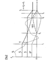
- Fig. 2 shows the time course of the forces acting in the coupling device 10 relevant forces during a disengaging operation.
- the Fig. 2 shows by way of example a profile of the friction force F R , which varies due to torque fluctuations in a drive train of a vehicle.
- the actuator force F A acts in the same direction - thus engaging. In the opposite direction, the spring force F F acts.
- the difference between the actuator force F A and the spring force F F is represented by the profile of ⁇ F (differential force).
- the forces F A , F F are constant, while the friction force F R varies over time.
- the solenoid valve 22 of the coupling device 10 of the Fig. 1 opened to reduce the pressure acting on the actuator 18 pressure p and thus causing a disengagement of the coupling device 10.
- the disengagement process does not start at time T 1 'when the forces F F , F R are the same for the first time after time T 1 . Because of the throttled pressure reduction, the actuator force F A initially decreases more slowly, which is also reflected in the course of the differential force ⁇ F.
- the behavior of the coupling device 10 can be influenced in a simple manner by a suitable choice of the throttle effect of the throttle 24 and a choice of the minimum pressure p min .
- a switching oscillation damaging the coupling device 10 can be prevented in an efficient manner, which leads to a reduced wear of all the components involved.
- the noise in a release process is reduced because a "pneumatic stop" is realized and a mechanical stop can be omitted.
- An adaptation of the throttle 24 and the pressure holding valve 28 makes it possible to use the coupling device 10 in various fields of application, without design changes are necessary. In particular, an individual adjustment of the spring force by providing a corresponding spring for the particular application is not necessary, but can be achieved by a suitable adjustment of the throttle 24 and the pressure holding valve 28.
Abstract
Description
Die vorliegende Erfindung betrifft eine Kupplungseinrichtung für einen Antriebsstrang eines Kraftfahrzeugs, mit einem ersten Kupplungsteil und einem zweiten Kupplungsteil, die selektiv formschlüssig miteinander in Eingriff bringbar sind.The present invention relates to a coupling device for a drive train of a motor vehicle, having a first coupling part and a second coupling part, which are selectively engageable with each other in a form-fitting manner.
Derartige Kupplungseinrichtungen finden insbesondere als Sperrenkupplung eines Differentialgetriebes Anwendung, beispielsweise in einem Achsdifferential oder einem Zentraldifferential eines Kraftfahrzeugs.Such coupling devices are used in particular as a lock clutch of a differential gear application, for example in an axle differential or a central differential of a motor vehicle.
Sperrenkupplungen mit rotierenden, formschlüssig zusammenwirkenden Kupplungsteilen haben den Vorteil, dass sie in der Lage sind, zuverlässig sehr hohe Drehmomente zu übertragen. Reibungskupplungen mit einer ähnlichen Leistungsfähigkeit sind deutlich größer und teurer als Kupplungseinrichtungen der eingangs genannten Art. Formschlüssige Kupplungseinrichtungen sind allerdings mit dem Nachteil behaftet, dass sie - verglichen mit ähnlich leistungsfähigen Reibungskupplungen - schwieriger zu steuern sind. Ein Einrücken derartiger Kupplungseinrichtungen setzt grundsätzlich voraus, dass zwischen den beiden Kupplungsteilen keine oder lediglich eine geringe Drehzahldifferenz vorliegt. Für ein Ausrücken muss eine ausreichend niedrige Drehmomentübertragung vorliegen. Insbesondere kann beim Ausrücken eine große aufzubringende Schaltkraft erforderlich sein, da zwischen den formschlüssig ineinander greifenden Komponenten der Kupplungsteile eine einem Ausrücken entgegenwirkende axiale Reibungskraft wirkt, die unter anderem von dem Betrag des durch die Kupplungseinrichtung momentan übertragenen Drehmoments abhängt.Lock clutches with rotating, positively cooperating coupling parts have the advantage that they are able to reliably transmit very high torques. Friction clutches with a similar performance are significantly larger and more expensive than coupling devices of the type mentioned. However, positive coupling devices have the disadvantage that they are more difficult to control compared to similarly powerful friction clutches. In principle, engagement of such coupling devices requires that there is no or only a slight difference in rotational speed between the two coupling parts. For a disengagement, a sufficiently low torque transmission must be present. In particular, when disengaging a large applied switching force may be required because between the form-fitting interlocking components of the coupling parts a disengaging counteracting axial frictional force acts, inter alia, on the amount of torque currently transmitted by the coupling device depends.
Die
Da jedoch die beim Ausrücken zu überwindende Reibungskraft nicht nur von dem über die Kupplung übertragenen Drehmoment, sondern unter anderem auch von der Dimension und Ausgestaltung der Kupplungsteile abhängt, muss für jede Variante der Kupplungseinrichtung eine Druckfeder mit geeigneten Eigenschaften bereitgestellt werden, damit ein selbsttätiges Ausrücken in der gewünschten Weise erfolgen kann. Verschleißerscheinungen an den Komponenten der Kupplungseinrichtung führen zudem zu einer Verschiebung des Schwellenwertes, bei dem das selbständige Ausrücken eingeleitet wird. Diese Verschiebung lässt sich nur durch den kostspieligen Austausch der betroffenen Komponenten kompensieren.However, since the frictional force to be overcome when disengaging depends not only on the torque transmitted through the clutch, but also on the dimension and configuration of the clutch parts, a compression spring with suitable properties must be provided for each variant of the clutch device, so that an automatic disengagement in the desired way can be done. Wear phenomena on the components of the coupling device also lead to a shift in the threshold value at which the autonomous disengagement is initiated. This shift can only be compensated by the costly replacement of the affected components.
Nachteilig ist bei der vorstehend beschriebenen Konstruktion ferner, dass das axial bewegte Kupplungsteil bei einem Wegfall der Reibungskraft - d.h. zu dem Zeitpunkt des Ausrückvorgangs, in dem der Formschluss zwischen den Kupplungsteilen aufgehoben wird - plötzlich ungehindert beschleunigt wird. Dies führt zu einem erhöhten Verschleiß der beteiligen Komponenten und damit zu einer verringerten Lebensdauer der Kupplungseinrichtung. Außerdem treten störende Schaltgeräusche auf.A further disadvantage of the construction described above is that the axially moving coupling part is displaced when the frictional force is eliminated - i.e. At the time of the disengagement process, in which the positive connection between the coupling parts is canceled - is suddenly accelerated unhindered. This leads to increased wear of the components involved and thus to a reduced service life of the coupling device. In addition, disturbing switching noises occur.
Ein weiterer nachteiliger Effekt, der bei bekannten Kupplungseinrichtungen beobachtet werden kann, ist das sogenannte Schaltpendeln. Es kann auftreten, wenn es während des Ausrückvorgangs zu vergleichsweise großen Schwankungen des durch die Kupplungseinrichtung übertragenen Drehmoments kommt, z.B. bei "Stick-Slip"-Effekten an den Reifen und einem schnellen Ausschalten einer die Kupplungsteile einrückenden Aktuatoreinheit. Dies führt zu einer raschen Abfolge von unerwünschten Ein- und Ausrückvorgängen, die eine reduzierte Traktion eines die Kupplungseinrichtung umfassenden Antriebsstrangs eines Fahrzeugs und eine starke Beanspruchung der Kupplungseinrichtung nach sich ziehen.Another disadvantageous effect which can be observed in known coupling devices is the so-called switching oscillation. It can occur if during the disengagement process comparatively large fluctuations of the torque transmitted by the coupling device occur, e.g. in "stick-slip" effects on the tire and a quick turn off the clutch unit engaging actuator unit. This leads to a rapid succession of undesired engagement and disengagement operations, resulting in reduced traction of a powertrain of the vehicle comprising the clutch device and heavy stress on the clutch device.
Ferner ist zu berücksichtigen, dass bei einer pneumatisch aktuierten Kupplungseinrichtung gefährliche Blockaden durch Vereisung auftreten können. Wird nämlich die einen Aktuator der Kupplungseinrichtung beaufschlagende Druckluft abrupt abgelassen, um die Kupplungseinrichtung auszurücken, so entweicht die Druckluft unter sehr schneller Expansion in die Umgebung. Dabei tritt eine Abkühlung auf, die zu einem Gefrieren von Feuchtigkeitsspuren im Bereich des Aktuators, insbesondere im Bereich einer Druckabbauleitung des Aktuators führen kann. Im Extremfall werden der Aktuator und/oder die Druckabbauleitung durch die Vereisung blockiert, so dass die Kupplungseinrichtung nicht mehr ordnungsgemäß betrieben werden kann.It should also be noted that dangerous blockages due to icing may occur in a pneumatically actuated clutch device. Namely, when the compressed air applied to an actuator of the clutch device is exhausted abruptly to disengage the clutch device, the compressed air escapes into the environment under very rapid expansion. In this case, a cooling occurs, which can lead to a freezing of traces of moisture in the region of the actuator, in particular in the region of a pressure reduction line of the actuator. In extreme cases, the actuator and / or the pressure reduction line through the icing blocked, so that the coupling device can not be operated properly.
Es ist daher eine Aufgabe der vorliegenden Erfindung, eine flexibel einsetzbare Kupplungseinrichtung der vorstehend genannte Art zu schaffen, die ein zuverlässiges und schonendes Ausrücken der Kupplungsteile sicherstellt.It is therefore an object of the present invention to provide a flexible coupling device of the aforementioned type, which ensures a reliable and gentle disengagement of the coupling parts.
Die Lösung dieser Aufgabe erfolgt durch eine Kupplungseinrichtung mit den Merkmalen des Anspruchs 1.The solution of this object is achieved by a coupling device with the features of claim 1.
Wie bereits erwähnt, weist die Kupplungseinrichtung ein erstes Kupplungsteil und ein zweites Kupplungsteil auf, die selektiv formschlüssig miteinander in Eingriff bringbar sind. Ferner ist eine Steuereinrichtung vorgesehen, die eine Ausrückeinheit und eine mittels eines Fluiddrucks betreibbare Aktuatoreinheit umfasst. Durch die Ausrückeinheit ist eine die Kupplungsteile ausrückende Kraft erzeugbar, während durch die Aktuatoreinheit eine die Kupplungsteile einrückende Kraft erzeugbar ist.As already mentioned, the coupling device has a first coupling part and a second coupling part, which are selectively engageable with each other in a form-locking manner. Furthermore, a control device is provided which comprises a disengaging unit and an actuator unit which can be operated by means of a fluid pressure. Through the disengagement unit, a force disengaging the coupling parts can be generated, while a force engaging the coupling parts can be generated by the actuator unit.
Erfindungsgemäß ist der Steuereinrichtung eine Druckhalteeinrichtung zugeordnet, um einen die Aktuatoreinheit beaufschlagenden Fluiddruck gemäß einer vorbestimmten Charakteristik abzubauen. Es ist also nicht vorgesehen, die einrückende Kraft schlagartig auf Null absinken zu lassen, um ein Ausrücken der Kupplungseinrichtung zu bewirken, sondern die Reduktion der einrückenden Kraft wird durch die Druckhalteeinrichtung beeinflusst. Beispielsweise wird der Ausrückvorgang durch einen verzögerten Druckabbau sanfter gestaltet, wodurch die beteiligen Komponenten weniger belastet werden, ohne dass die Dynamik der Kupplungseinrichtung in relevantem Maße leidet. Auch ein Schaltpendeln kann effizient verhindert werden, da der Druckabbau in der Aktuatoreinheit gemäß einer geeigneten Zeitkonstante erfolgen kann. Ferner ermöglicht eine Modifikation der Druckhalteeinrichtung eine Anpassung ihrer Druckabbaucharakteristik, wodurch die Kupplungseinrichtung justiert werden kann, um beispielsweise Verschleißerscheinungen zu kompensieren oder geänderten Anforderungen an die Schaltdynamik der Kupplungseinrichtung Rechnung zu tragen. Die Druckhalteeinrichtung kann somit auch als Druckabbausteuereinrichtung bezeichnet werden.According to the invention, the control device is assigned a pressure-retaining device in order to reduce a fluid pressure acting upon the actuator unit in accordance with a predetermined characteristic. It is therefore not intended to allow the engaging force to abruptly drop to zero to cause disengagement of the clutch device, but the reduction of the engaging force is influenced by the pressure-holding device. For example, the disengagement process is softened by a delayed pressure reduction, whereby the components involved are less stressed, without the dynamics of the coupling device suffering to a relevant extent. Also, a switching oscillation can be prevented efficiently since the pressure reduction in the actuator unit according to a suitable time constant can be done. Furthermore, a modification of the pressure holding device allows an adaptation of their pressure application characteristics, whereby the coupling device can be adjusted to compensate for wear, for example, or to take into account changed requirements for the switching dynamics of the coupling device. The pressure-maintaining device can thus also be referred to as a pressure-release control device.
Mit anderen Worten basiert die Funktionsweise der vorstehend beschriebenen Kupplungseinrichtung auf einer bewussten Beeinflussung eines Kräftegleichgewichts zwischen einrückenden und ausrückenden Kräften mit Hilfe der Druckhalteeinrichtung. Zu einem Ausrücken der Kupplungseinrichtung kommt es, wenn die von der Ausrückeinheit bereitgestellte Kraft die Summe der das Ausrücken verhindernden Kräfte - nämlich der Reibungskraft und der durch die Aktuatoreinheit erzeugten Einrückkraft - überschreitet. Eine vorbestimmte Charakteristik des Abbaus des die Aktuatoreinheit beaufschlagenden Fluiddrucks ermöglicht eine bessere Kontrolle über dieses Kräftegleichgewicht und somit über den Ausrückvorgang, so dass dieser nicht von Fluktuationen des während des Ausrückens durch die Kupplungseinrichtung übertragenen Drehmoments und damit von der zwischen den Kupplungsteilen wirkenden Reibungskraft dominiert wird. Insbesondere wird ein vorzeitiges Ausrücken der Kupplungseinrichtung - und damit letztlich das Auftreten von Schaltpendeln - verhindert.In other words, the operation of the coupling device described above is based on deliberately influencing a balance of forces between engaging and disengaging forces with the aid of the pressure-retaining device. A disengagement of the coupling device occurs when the force provided by the disengaging unit exceeds the sum of the disengaging forces - namely, the friction force and the engagement force generated by the actuator unit. A predetermined characteristic of the degradation of the fluid pressure applied to the actuator unit allows better control over this balance of forces and thus over the disengagement process, so that it is not dominated by fluctuations in the torque transmitted by the clutch means during disengagement and thus by the frictional force acting between the clutch members. In particular, a premature disengagement of the coupling device - and thus ultimately the occurrence of switching pendulums - prevented.
Bei dem verwendeten Arbeitsfluid zum Beaufschlagen der Aktuatoreinheit kann es sich um Luft handeln (pneumatisches Betreiben der Aktuatoreinheit) oder um eine Flüssigkeit, insbesondere Öl (hydraulisches Betreiben der Aktuatoreinheit). Der Fluiddruck in dem Aktuator kann beispielsweise durch einen angeschlossenen Druckspeicher oder durch eine Pumpe erzeugt werden. In dem letztgenannten Fall ist es bevorzugt, wenn die Pumpe nicht in Abhängigkeit einer Drehzahldifferenz zwischen den beiden Kupplungsteilen, sondern unabhängig hiervon angetrieben wird. Andernfalls erfolgt das Einrücken der formschlüssig zusammenwirkenden Kupplungsteile zu langsam oder ist aufgrund der bereits aufgebauten Drehzahldifferenz überhaupt nicht mehr möglich.The working fluid used to act on the actuator unit may be air (pneumatic actuation of the actuator unit) or a fluid, in particular oil (hydraulic actuation of the actuator unit). The fluid pressure in the actuator can be generated, for example, by a connected pressure accumulator or by a pump become. In the latter case, it is preferred that the pump is not driven in response to a speed difference between the two coupling parts, but independently thereof. Otherwise, the engagement of the form-fitting co-operating coupling parts is too slow or is no longer possible due to the already built-up speed difference.
Es ist ausreichend und bevorzugt, wenn die genannte Druckhalteeinrichtung lediglich auf das Arbeitsfluid der Aktuatoreinheit wirkt. Hierdurch unterscheidet sich die genannte Druckhalteeinrichtung beispielsweise von Drosselventilen oder Rückschlagventilen, die bei bekannten Kupplungen mit flüssigem Arbeitsfluid zum Entlüften eines Druckraums dienen.It is sufficient and preferred if said pressure-maintaining device acts only on the working fluid of the actuator unit. As a result, the said pressure-retaining device differs, for example, from throttle valves or check valves, which serve in known couplings with liquid working fluid for venting a pressure chamber.
Gemäß einer vorteilhaften Ausführungsform umfasst die Druckhalteeinrichtung eine Drosseleinrichtung, mit welcher der die Aktuatoreinheit beaufschlagende Fluiddruck in vorbestimmter Weise gedrosselt abbaubar ist. Durch die gedrosselte Reduktion des Fluiddrucks wird die Kupplungseinrichtung nach einem Deaktivieren der Aktuatoreinheit bis zum Erreichen des vorstehend beschriebenen Kräftegleichgewichts noch für einen bestimmten Zeitraum sicher geschlossen gehalten. Dadurch kann beispielsweise ein Schaltpendeln in Situationen verhindert werden, in denen die zwischen den Kupplungsteilen wirkende Reibungskraft aufgrund von Drehmomentfluktuationen nach einem Abschalten der Aktuatoreinheit sehr schnell auf geringe Werte absinkt und anschließend wieder deutlich ansteigt.According to an advantageous embodiment, the pressure-retaining device comprises a throttle device with which the fluid pressure acting upon the actuator unit can be reduced in a predetermined manner in a throttled manner. Due to the throttled reduction of the fluid pressure, the clutch device is kept securely closed for a certain period of time after deactivation of the actuator unit until reaching the power balance described above. As a result, for example, a switching oscillation can be prevented in situations in which the frictional force acting between the coupling parts very quickly drops to low values due to torque fluctuations after the actuator unit has been switched off, and then increases significantly again.
Da die Drosseleinrichtung wie erläutert zum Verzögern des Ausrückens der Kupplungsteile dient, ist es nicht erforderlich, dass die Drosseleinrichtung eine temperaturabhängige oder temperaturkompensierende Drosselcharakteristik besitzt. Damit die Drosseleinrichtung einen vorteilhaft einfachen Aufbau besitzt, ist es bevorzugt, wenn die Drosseleinrichtung keine temperaturabhängige oder temperaturkompensierende Drosselcharakteristik besitzt.Since the throttle device is used as described for delaying the disengagement of the coupling parts, it is not necessary that the throttle device has a temperature-dependent or temperature-compensating throttle characteristic. So that the throttle device advantageous has simple structure, it is preferred if the throttle device has no temperature-dependent or temperature-compensating throttle characteristic.
Alternativ oder zusätzlich zu der Drosseleinrichtung ist es möglich, dass die Druckhalteeinrichtung ein Druckhalteventil umfasst, mit dem ein die Aktuatoreinheit beaufschlagender minimaler Fluiddruck, d.h. ein vorbestimmter Haltedruck aufrechterhalten wird. Mit anderen Worten ist ein die Aktuatoreinheit beaufschlagender Fluiddruck mittels des Druckhalteventils lediglich bis zu einem vorbestimmten minimalen Fluiddruck abbaubar. Der minimale Fluiddruck definiert, bis wann im eingerückten Zustand der Kupplungseinrichtung noch ein Kräftegleichgewicht zwischen der ausrückenden Kraft der Ausrückeinheit einerseits und der axialen Reibungskraft sowie der von der Aktuatoreinheit erzeugten einrückenden Kraft andererseits herrscht. Der mittels des Druckhalteventils vorgebbare minimale Fluiddruck legt im Ergebnis fest (im Falle des zusätzlichen Vorhandenseins der vorgenannten Drosseleinrichtung spätestens nach der gedrosselten Reduktion des Fluiddrucks), welches übertragene Drehmoment unterschritten werden muss, damit die Ausrückeinheit die Kupplungsteile voneinander entfernt. Somit kann durch die Wahl eines geeigneten minimalen Fluiddrucks der Schaltpunkt des selbsttätigen Ausrückens der Kupplungseinrichtung beeinflusst werden, ohne dass hierfür die Ausrückeinheit (z.B. Druckfeder) ausgetauscht werden muss.As an alternative or in addition to the throttle device, it is possible for the pressure-retaining device to comprise a pressure-holding valve, with which a minimum fluid pressure acting on the actuator unit, i. a predetermined holding pressure is maintained. In other words, a fluid pressure acting on the actuator unit is degradable by means of the pressure holding valve only up to a predetermined minimum fluid pressure. The minimum fluid pressure defines until when in the engaged state of the clutch device nor a balance of forces between the disengaging force of the disengaging unit on the one hand and the axial friction force and the force generated by the actuator unit Einrückenden force prevails. The predetermined by means of the pressure holding valve minimum fluid pressure determines in the result (in the case of the additional presence of the aforementioned throttle device at the latest after the throttled reduction of the fluid pressure), which transmitted torque must be exceeded, so that the disengaging unit removes the coupling parts from each other. Thus, by choosing a suitable minimum fluid pressure, the switching point of the automatic disengagement of the clutch device can be influenced without having to exchange the disengaging unit (for example compression spring) for this purpose.
Die Sicherstellung eines minimalen Fluiddrucks kann auch als pneumatischer oder hydraulischer "Anschlag" für die Aktuatoreinheit genutzt werden. Durch die Wahl des minimalen Fluiddrucks kann folglich die Ruheposition des axial bewegbaren Kupplungsteils im ausgerückten Zustand definiert und damit die Kupplungseinrichtung justiert und an veränderte Bedingungen angepasst werden. Insbesondere kann durch die Wahl einer geeigneten Ruheposition des axial bewegbaren Kupplungsteils der beim Einrücken der Kupplungsreinrichtung zu überwindende Lüftweg minimiert und damit die Schaltdynamik der Kupplungseinrichtung optimiert werden.Ensuring a minimum fluid pressure can also be used as a pneumatic or hydraulic "stop" for the actuator unit. By choosing the minimum fluid pressure consequently, the rest position of the axially movable coupling part can be defined in the disengaged state and thus the coupling device adjusted and adapted to changing conditions. In particular, by choosing a suitable rest position of the axially movable coupling part minimizes the to be overcome when engaging the clutch device Lüftweg and thus the switching dynamics of the coupling device can be optimized.
Ein weiterer Vorteil eines Druckhalteventils besteht insbesondere bei pneumatischen Aktuatoreinheiten darin, dass der auf die Aktuatoreinheit wirkende minimale Druck der Druckluft so gewählt werden kann, dass er über dem Umgebungsdruck liegt. Ein Eindringen von Feuchtigkeit in die Aktuatoreinheit ist daher nicht möglich und die Gefahr von Vereisung wird ausgeschaltet.A further advantage of a pressure-maintaining valve, especially in the case of pneumatic actuator units, is that the minimum pressure of the compressed air acting on the actuator unit can be chosen such that it is above the ambient pressure. Ingress of moisture into the actuator unit is therefore not possible and the risk of icing is eliminated.
Bevorzugt ist der genannte, die Aktuatoreinheit beaufschlagende minimale Fluiddruck geringer als der zum Einrücken der Kupplungsteile vorgesehene Fluiddruck. Dadurch wird ein zuverlässiges Ausrücken der Kupplungseinrichtung gewährleistet, während gleichzeitig verhindert wird, dass der die Aktuatoreinheit beaufschlagende Fluiddruck vollkommen abgebaut wird.Preferably, said minimum actuator fluid pressure acting on the actuator unit is less than the fluid pressure provided to engage the clutch members. This ensures a reliable disengagement of the coupling device, while at the same time preventing the fluid pressure acting on the actuator unit from being completely dissipated.
Vorzugsweise ist nach Abschalten der Aktuatoreinheit bei noch eingerückten Kupplungsteilen und bei einem sehr geringen übertragenen Drehmoment an den Kupplungsteilen die ausrückende Kraft der Ausrückeinheit betragsmäßig kleiner als (nämlich während des gedrosselten Druckabbaus) bzw. im Wesentlichen gleich (nämlich nach Erreichen des genannten minimalen Fluiddrucks) der Summe der axialen Reibungskraft zwischen den Kupplungsteilen und der durch den momentanen Fluiddruck verursachten einrückenden Kraft der Aktuatoreinheit. Die Kupplungsteile rücken somit selbsttätig aus, wenn die ausrückende Kraft die Summe der axialen Reibungskraft und der einrückenden Kraft des Aktuators übersteigt. Dadurch wird sichergestellt, dass kein vorzeitiges Aufheben des Formschlusses zwischen den Kupplungsteilen erfolgt.Preferably, after switching off the actuator unit with still engaged clutch parts and at a very low torque transmitted to the coupling parts, the disengaging force of the disengaging unit is smaller than (ie during the throttled pressure reduction) or substantially equal (namely after reaching said minimum fluid pressure) of Sum of the axial frictional force between the coupling parts and the engaging force of the actuator unit caused by the instantaneous fluid pressure. The coupling parts thus automatically move out when the disengaging force exceeds the sum of the axial friction force and the engaging force of the actuator. This ensures that no premature cancellation of the positive connection between the coupling parts takes place.
Wenn die Drosseleinrichtung und/oder das Druckhalteventil variabel einstellbar sind, kann auf einfache Weise die vorbestimmte Charakteristik des Druckabbaus modifiziert werden, um beispielsweise einen Verschleiß der Kupplungsteile, der Ausrückeinheit oder anderer Komponenten der Kupplungseinrichtung zu kompensieren oder um die Schaltdynamik der Kupplungseinrichtung zu justieren. Grundsätzlich können die Drosseleinrichtung und/oder das Druckhalteventil aktiv einstellbar sein, um beispielsweise in bestimmten Situationen einen schnellen Eingriff in die Eigenschaften der Kupplungseinrichtung zu ermöglichen. Bevorzugt ist es allerdings, wenn die Drosseleinrichtung und/oder das Druckhalteventil passive Bauteile sind.If the throttle device and / or the pressure holding valve are variably adjustable, the predetermined characteristic of the pressure reduction can be modified in a simple manner, for example, to compensate for wear of the coupling parts, the disengaging unit or other components of the coupling device or to adjust the switching dynamics of the coupling device. In principle, the throttle device and / or the pressure-maintaining valve can be actively adjustable in order, for example, to permit rapid intervention in the characteristics of the clutch device in certain situations. However, it is preferred if the throttle device and / or the pressure holding valve are passive components.
Ferner kann vorgesehen sein, dass die Druckhalteeinrichtung in einer Druckabbauleitung angeordnet ist, die mit der Aktuatoreinheit in Verbindung steht und durch die der die Aktuatoreinheit beaufschlagende Fluiddruck abbaubar ist. Die Druckabbauleitung kann durch ein Sperrventil selektiv sperrbar sein. Das Sperrventil kann beispielsweise als ein Magnetventil ausgebildet sein.Furthermore, it can be provided that the pressure-retaining device is arranged in a pressure reduction line, which is in communication with the actuator unit and through which the fluid pressure acting on the actuator unit is degradable. The pressure reduction line can be selectively blocked by a check valve. The check valve may be formed, for example, as a solenoid valve.
Eine Sperrung der Druckabbauleitung ist insbesondere bei einem Aufbau des Fluiddrucks vorgesehen, also wenn der Aktuatoreinheit Fluid über eine Druckaufbauleitung zugeführt wird, um die Kupplungsteile einzurücken. Ferner kann das Sperrventil dazu dienen, den Fluiddruck in der Aktuatoreinheit im Wesentlichen (d.h. abgesehen von unvermeidlichen Leckageverlusten) aufrechtzuerhalten, um die Kupplungsteile - solange die Druckabbauleitung gesperrt ist - sicher eingerückt zu halten. Das Ausrücken der Kupplungsteile hingegen wird aufgrund der Wirkung der Ausrückeinheit durch Öffnen des Sperrventils, d.h. durch Freigeben der Druckabbauleitung, ausgelöst, wobei die genannte Drosseleinrichtung das erläuterte zeitliche Verzögern des Ausrückens der Kupplungsteile bewirken kann.A blockage of the pressure reduction line is provided in particular in a structure of the fluid pressure, that is, when the actuator unit fluid is supplied via a pressure build-up line to engage the coupling parts. Further, the check valve may serve to substantially maintain fluid pressure in the actuator unit (ie, apart from unavoidable leakage losses) to keep the clutch parts securely engaged as long as the pressure relief line is locked. The disengagement of the coupling parts, however, is due to the action of the disengaging unit by opening the check valve, ie by releasing the pressure reduction line, triggered, said throttle means can cause the described time delaying the disengagement of the coupling parts.
Bei einem besonders einfachen Aufbau der Aktuatoreinheit, nämlich mit einem einzigen Sperrventil und einer einzigen Anschlussleitung zwischen dem Sperrventil und dem Druckraum der Aktuatoreinheit, ist die Druckhalteeinrichtung, insbesondere das genannte Druckhalteventil, im Unterschied zu einem typischen Überdruckventil vorzugsweise an einer der Aktuatoreinheit abgewandten Seite des Sperrventils angeordnet, d.h. stromabwärts des Sperrventils bezüglich der Strömungsrichtung bei Druckabbau. Somit kann durch Schließen des Sperrventils verhindert werden, dass die Druckhalteeinrichtung einem erwünschten Aufbau des Fluiddrucks zum Einrücken der Kupplungsteile entgegenwirkt. Falls hingegen zusätzlich zu der Druckabbauleitung mit Sperrventil eine separate Druckaufbauleitung mit eigenem Sperrventil vorgesehen ist, wobei beide Leitungen mit dem Druckraum der Aktuatoreinheit verbunden sind, so kann die Druckhalteeinrichtung grundsätzlich an beliebiger Stelle entlang der Druckabbauleitung angeordnet sein.In a particularly simple construction of the actuator unit, namely with a single shut-off valve and a single connection line between the shut-off valve and the pressure chamber of the actuator unit, the pressure-retaining device, in particular the said pressure-holding valve, in contrast to a typical pressure relief valve, is preferably on a side of the shut-off valve facing away from the actuator unit arranged, ie downstream of the check valve with respect to the flow direction when pressure is reduced. Thus, by closing the check valve, it can be prevented that the pressure-holding device counteracts a desired structure of the fluid pressure for engaging the coupling parts. If, in contrast to the pressure reduction line with check valve, a separate pressure buildup line is provided with its own check valve, both lines are connected to the pressure chamber of the actuator, the pressure holding device can be arranged at any point along the pressure reduction line.
Die Aktuatoreinheit kann hydraulisch oder pneumatisch betreibbar sein.The actuator unit can be operated hydraulically or pneumatically.
Insbesondere bei einer pneumatisch betriebenen Aktuatoreinheit kann die genannte Druckabbauleitung mit der Umgebungsluft in Verbindung stehen. Bei einer hydraulisch betriebenen Aktuatoreinheit kann die genannte Druckabbauleitung in einen Sumpf für das Fluid münden.In particular, in the case of a pneumatically operated actuator unit, said pressure reduction line may be in communication with the ambient air. In a hydraulically operated actuator unit, said pressure reduction line can open into a sump for the fluid.
Eine kompakte Bauweise lässt sich erreichen, wenn die Drosseleinrichtung, das Druckhalteventil und/oder das Sperrventil zu einer Baueinheit zusammengefasst sind.A compact design can be achieved if the throttle device, the pressure holding valve and / or the check valve are combined to form a unit.
Die genannte Druckabbauleitung bildet vorzugsweise einen Hauptverbindungspfad, der von der Aktuatoreinheit (z.B. von einem Druckraum für einen Kolben) zu der Umgebung der Kupplungseinrichtung (bei Verwendung von Druckluft) oder zu einem Sumpf führt (bei Verwendung eines flüssigen Arbeitsfluids). Mit anderen Worten soll die Druckhalteeinrichtung nicht in einem Nebenverbindungspfad für das Fluid (z.B. Rückkopplungspfad) wirken, sondern in einer direkten Verbindung zwischen der Aktuatoreinheit und der Fluidaufnahme (Umgebungsluft oder Sumpf). Hierdurch wird erreicht, dass der erwünschte Druckhalteeffekt zuverlässig und reproduzierbar erreicht wird, um den Fluiddruck gemäß der vorbestimmten Charakteristik abzubauen.Said depressurizing conduit preferably forms a main communication path leading from the actuator unit (e.g., from a pressure space for a piston) to the environment of the coupling means (using compressed air) or to a sump (when using a liquid working fluid). In other words, the pressure maintaining means should not act in a secondary communication path for the fluid (e.g., feedback path), but in a direct connection between the actuator unit and the fluid intake (ambient air or sump). This ensures that the desired pressure-holding effect is reliably and reproducibly achieved in order to reduce the fluid pressure in accordance with the predetermined characteristic.
Insbesondere kann eine einzige Druckabbauleitung vorgesehen sein, über die der die Aktuatoreinheit beaufschlagende Fluiddruck abbaubar ist, wobei die Druckhalteeinrichtung in dieser einzigen Druckabbauleitung angeordnet oder wirksam ist.In particular, a single pressure reduction line can be provided, via which the fluid pressure acting on the actuator unit is degradable, wherein the pressure maintenance device is arranged or operative in this single pressure reduction line.
Weiterhin ist es bevorzugt, wenn die genannte Druckhalteeinrichtung lediglich in der Druckabbauleitung angeordnet oder wirksam ist, nicht jedoch in einer Druckaufbauleitung (d.h. Fluidzufuhrleitung), durch die der Fluiddruck in der Aktuatoreinheit aufgebaut wird. Mit anderen Worten soll die Druckhalteeinrichtung nicht die Zufuhr des Arbeitsfluids zu der Aktuatoreinheit (z.B. Druckraum für einen Kolben) behindern, damit ein Einrücken der Kupplungsteile nicht verzögert wird. Bei einer formschlüssig wirksamen Kupplungseinrichtung ist es wichtig, dass das Einrücken schnell erfolgt, bevor die Drehzahldifferenz zu groß wird.Further, it is preferable that said pressure-maintaining means is disposed or operative only in the depressurizing conduit, but not in a pressure-establishing conduit (ie, fluid supply conduit), by which the fluid pressure in the actuator unit is established. In other words, the pressure-maintaining device should not hinder the supply of the working fluid to the actuator unit (eg pressure chamber for a piston), so that an engagement of the coupling parts is not delayed. In a form-fitting coupling device, it is important that the engagement occurs quickly before the speed difference is too large.
Eine konstruktiv einfache und gleichwohl effiziente Ausgestaltung der Ausrückeinheit umfasst eine Druckfeder, welche die Kupplungsteile in Ausrückrichtung vorspannt.A structurally simple and yet efficient embodiment of the disengaging unit comprises a compression spring which biases the coupling parts in the disengagement direction.
Die Erfindung bezieht sich auch auf eine Kupplungseinrichtung für einen Antriebsstrang eines Kraftfahrzeugs, mit einem ersten Kupplungsteil und einem zweiten Kupplungsteil, die selektiv formschlüssig miteinander in Eingriff bringbar sind; einer Druckfeder, welche das erste Kupplungsteil und das zweite Kupplungsteil in einer Ausrückrichtung vorspannt; einer Aktuatoreinheit, die mittels eines Fluiddrucks betreibbar ist, um das erste Kupplungsteil und das zweite Kupplungsteil entgegen der Ausrückrichtung einzurücken; einer Druckabbauleitung, die von der Aktuatoreinheit zu einer Fluidaufnahme führt und zum Abbauen eines in der Aktuatoreinheit aufgebauten Fluiddruck vorgesehen ist; und einer Druckhalteeinrichtung, die in der Druckabbauleitung wirksam ist, um den in der Aktuatoreinheit aufgebauten Fluiddruck gemäß einer vorbestimmten Charakteristik abzubauen. Die vorstehend erläuterten Ausführungsformen und Weiterbildungen lassen sich auch auf eine solche Kupplungseinrichtung übertragen.The invention also relates to a coupling device for a drive train of a motor vehicle, having a first coupling part and a second coupling part, which are selectively engageable with each other in a form-locking manner; a compression spring biasing the first coupling part and the second coupling part in a disengagement direction; an actuator unit operable by a fluid pressure to engage the first clutch part and the second clutch part against the disengagement direction; a depressurizing pipe leading from the actuator unit to a fluid intake and provided for discharging a fluid pressure built up in the actuator unit; and a pressure-holding means operative in the depressurizing duct to decompose the fluid pressure built up in the actuator unit according to a predetermined characteristic. The embodiments and further developments explained above can also be transferred to such a coupling device.
Die Erfindung betrifft ferner ein Verfahren zum Steuern einer Kupplungseinrichtung mit formschlüssig zusammenwirkenden und selektiv miteinander in Eingriff bringbaren Kupplungsteilen. Die Kupplungseinrichtung weist eine Steuereinrichtung auf, die eine Ausrückeinheit und eine mittels eines Fluiddrucks betreibbare Aktuatoreinheit umfasst. Durch die Ausrückeinheit ist eine die Kupplungsteile ausrückende Kraft erzeugbar, während durch die Aktuatoreinheit eine die Kupplungsteile einrückende Kraft erzeugbar ist. Zum Ausrücken der Kupplungsteile wird über eine Druckhaltevorrichtung der die Aktuatoreinheit beaufschlagende Fluiddruck gemäß einer vorbestimmten Charakteristik abgebaut. Insbesondere wird der Fluiddruck gedrosselt abgebaut. Alternativ oder zusätzlich zu einem gedrosselten Druckabbau kann vorgesehen sein, dass der die Aktuatoreinheit beaufschlagende Fluiddruck nur so weit abgebaut wird, dass ein Minimaldruckniveau (d.h. der vorgenannte minimale Fluiddruck) nicht unterschritten wird.The invention further relates to a method for controlling a coupling device with positively cooperating and selectively engageable coupling parts. The coupling device has a control device which comprises a disengaging unit and an actuator unit which can be operated by means of a fluid pressure. Through the disengagement unit, a force disengaging the coupling parts can be generated, while a force engaging the coupling parts can be generated by the actuator unit. To disengage the coupling parts, the fluid pressure acting on the actuator unit is transmitted via a pressure-retaining device degraded according to a predetermined characteristic. In particular, the fluid pressure is degraded throttled. As an alternative or in addition to a throttled pressure reduction, it may be provided that the fluid pressure acting upon the actuator unit is only reduced to such an extent that it does not fall below a minimum pressure level (ie the aforementioned minimum fluid pressure).
Weitere Ausführungsformen der Erfindung sind in der Beschreibung, den Ansprüchen und den beigefügten Zeichnungen angegeben.Further embodiments of the invention are indicated in the description, the claims and the attached drawings.
Nachfolgend werden vorteilhafte Ausführungsformen der vorliegenden Erfindung rein beispielhaft unter Bezugnahme auf die beigefügten Zeichnungen erläutert. Es zeigen:
- Fig. 1
- eine Schemazeichnung einer Ausführungsform der erfindungsgemäßen Kupplungseinrichtung,
- Fig. 2
- ein Diagramm zur Verdeutlichung des zeitlichen Verlaufs der während eines Ausrückvorgangs in der Kupplungseinrichtung auftretenden Kräfte.
- Fig. 1
- a schematic drawing of an embodiment of the coupling device according to the invention,
- Fig. 2
- a diagram illustrating the timing of the forces occurring during a disengagement in the coupling device forces.
Auf das axial bewegliche Kupplungsteil 14 wirken eine Reihe von Kräften, um dieses selektiv in axialer Richtung bewegen zu können (symbolisch gekennzeichnet durch einen Doppelpfeil unterhalb des Kupplungsteils 14). Zum einen wirkt auf das Kupplungsteil 14 in Einrückrichtung eine durch einen Aktuator 18 erzeugte Aktuatorkraft FA. In dem vorliegenden Beispiel ist der Aktuator 18 pneumatisch betrieben, so dass die Aktuatorkraft FA eine Funktion eines ihm zugeführten Drucks p ist. Hierfür wird dem Aktuator 18 Druckluft aus einer Druckluftquelle Q über eine Druckaufbauleitung 17 und eine Anschlussleitung 19 zugeführt, um den Druck p in einem Druckraum des Aktuators 18 zu erhöhen.On the axially
Zum anderen wirkt auf das Kupplungsteil 14 in Ausrückrichtung eine durch eine Druckfeder 20 erzeugte Federkraft FF, die einem Eingriff der Kupplungsteile 12, 14 somit entgegenwirkt. Mit anderen Worten sind die Kupplungsteile 12, 14 durch die Druckfeder 20 in Ausrückrichtung vorgespannt. Die Federkraft FF ist eine Funktion eines Abstands x der Kupplungsteile 12, 14 (entsprechend der Federauslenkung). In einem Zustand x = 0 ist die Kupplungseinrichtung 10 vollständig eingerückt.On the other hand acts on the
Neben den Kräften FA, FF wirkt auf das axial bewegliche Kupplungsteil 14 eine Reibungskraft mit einer axialen Komponente FR (bezogen auf die Rotationsachse der Kupplungseinrichtung 10), sobald die Klauen 16 der Kupplungsteile 12, 14 in Eingriff gelangen und ein Drehmoment über die Kupplungsteile 12, 14 übertragen wird. Die Reibungskraft FR wirkt wie die Aktuatorkraft FA einem Ausrücken entgegen und hängt unter anderem von dem zwischen den Kupplungsteilen 12, 14 übertragenen Drehmoment, von der Ausgestaltung der Flanken der Klauen 16 und von deren Beschaffenheit ab. Die Reibungskraft FR kann außer der Reibung an den Klauen 16 der Kupplungsteile 12, 14 auch noch andere Reibkräfte enthalten, die der Bewegung des axial beweglichen Kupplungsteils 14 entgegenwirken.In addition to the forces F A , F F acting on the axially
In allgemeiner Form lässt sich das eine Bewegung des Kupplungsteils 14 definierende Kräftegleichgewicht wie folgt formulieren: 
wobei M der Betrag des durch die Kupplungseinrichtung übertragenen Drehmoments ist. Je größer das Drehmoment M ist, desto stärker wirken die Klauen 16 der Kupplungsteile 12, 14 zusammen, was zu einer höheren axialen Reibungskraft FR führt.In general terms, the balance of forces defining a movement of the
where M is the amount of torque transmitted by the clutch device. The greater the torque M, the stronger the
In einem eingerückten Zustand ist die Federkraft FF kleiner als die Summe der Aktuatorkraft FA und der Reibungskraft FR. Um ein Ausrücken zu bewirken, kann nun eine der beiden Kräfte FA, FR - oder beide - abgesenkt werden, bis die Summe der Kräfte FA, FR die Federkraft FF unterschreitet und die Kupplungseinrichtung 10 selbsttätig ausrückt. Bei einem Unterschreiten von FF sorgt die Feder 20 nämlich dafür, dass sich das axial bewegliche Kupplungsteil 14 von dem axialfest angeordneten Kupplungsteil 12 wegbewegt, bis die Klauen 16 nicht mehr im Eingriff sind.In an engaged state, the spring force F F is smaller than the sum of the actuator force F A and the friction force F R. In order to bring about disengagement, one of the two forces F A , F R - or both - can now be lowered until the sum of the forces F A , F R falls below the spring force F F and the
Eine Absenkung der Reibungskraft FR erfolgt beispielsweise dann, wenn das übertragene Drehmoment M abnimmt. Der Ausrückvorgang der Kupplungseinrichtung 10 setzt ein, wenn die Reibungskraft FR bei einer gegebenen Aktuatorkraft FA unter einen bestimmten Schwellenwert sinkt, so dass FF > FA + FR.A lowering of the frictional force F R takes place, for example, when the transmitted torque M decreases. The disengagement operation of the
Alternativ oder gleichzeitig kann die Aktuatorkraft FA abgesenkt werden, bis FF > FA + FR. Zu diesem Zweck wird der Druck p des den Aktuator 18 beaufschlagenden Druckfluids - hier beispielhaft Druckluft - verringert. Dazu wird ein Magnetventil 22 geöffnet, d.h. in die in
Durch Öffnen des Magnetventils 22 wird also ein Ausrücken der Kupplungseinrichtung 10 ausgelöst, wobei der Ausrückvorgang tatsächlich erst dann einsetzt, wenn die vorgenannte Bedingung FF > FA + FR erfüllt ist.By opening the
Um zu verhindern, dass der Druckabbau in dem Aktuator 18 schlagartig geschieht und dadurch ein unkontrolliertes Ausrücken der Kupplungseinrichtung 10 erfolgt, ist eine Drossel 24 in einer Druckabbauleitung 26 angeordnet, die den Aktuator 18 über das Magnetventil 22 mit der Umgebung U verbindet. Bei einer Öffnung des Magnetventils 22 wird der auf den Aktuator 18 wirkende Druck p gedrosselt abgebaut, um einen kontrollierten Ausrückvorgang zu gewährleisten. Insbesondere wird auch eine Beschleunigung des Kupplungsteils 14 unterbunden, die bei herkömmlichen Kupplungseinrichtungen auftritt, sobald die Klauen 16 ab einem bestimmten Punkt des Ausrückprozesses außer Eingriff geraten und damit die Reibungskraft FR schlagartig auf Null absinkt. Der gedrosselte Abbau des Fluiddrucks p gemäß einer vorbestimmten Charakteristik, die durch die Ausgestaltung der Drossel 24 bestimmt wird, ist ferner insbesondere dann von Vorteil, wenn vergleichsweise große Schwankungen des übertragenen Drehmoments M während des Ausrückprozesses vorliegen, da ein Schaltpendeln durch die Verhinderung eines verfrühten Ausrückens der Kupplungsteile 12, 14 vermieden wird.In order to prevent the pressure reduction occurring in the
Die Drosselwirkung der Drossel 24 kann aktiv oder passiv einstellbar sein, um die Ausrückdynamik der Kupplungseinrichtung 10 bedarfsgerecht anpassen zu können.The throttling action of the
Zusätzlich zu der Drossel 24 ist in der Druckabbauleitung 26 ein Druckhalteventil 28 vorgesehen, dessen Aufgabe es ist, dafür zu sorgen, dass stets ein vorbestimmtes minimales Druckniveau pmin den Aktuator 18 beaufschlagt, d.h. in der Druckkammer des Aktuators 18 aufrechterhalten bleibt. Durch das minimale Druckniveau pmin wirkt der Aktuator 18 als eine Art "Anschlag". Wenn die Kupplungseinrichtung 10 ausgerückt ist, wirkt bei FF = FA(pmin) keine Kraft mehr auf das Kupplungsteil 14 und folglich ist ein Gleichgewichtszustand erreicht, in dem das axial bewegliche Kupplungsteil 14 eine Ruheposition einnimmt.In addition to the
Mit anderen Worten ist das Druckhalteventil 28 ein Rückschlagventil, das auf seiner stromaufwärtigen Seite einen vorbestimmten Überdruck pmin aufrechterhält. Dadurch wird auch verhindert, dass Umgebungsluft in das pneumatische System eindringt und dort bei einem Druckabbau der Druckluft während eines Ausrückvorgangs zu Vereisungen führt. Außerdem kann somit ein neuerliches Einrücken der Kupplungseinrichtung 10 schneller eingeleitet werden, da im Vergleich zu einem vollständig entleerten Druckraum nur ein relativ geringer Druckaufbau im Aktuator 18 erforderlich ist. Der genannte minimale Druck pmin, der für das Druckhalteventil 28 die Schaltschwelle bildet, ist (anders als bei einem herkömmlichen Überdruckventil) geringer als der im Betrieb der Kupplungseinrichtung 10 zum Einrücken der Kupplungsteile 12, 14 verwendete Druck p. Nach dem gedrosselten Druckabbau auf das vorgenannte minimale Druckniveau pmin bezieht sich die vorgenannte Ausrückbedingung FF > FA + FR somit auf die bei pmin noch verbleibende Aktuatorkraft FA(pmin).In other words, the pressure holding valve 28 is a check valve which maintains a predetermined positive pressure p min on its upstream side. This also prevents ambient air from penetrating into the pneumatic system and leads to icing in a pressure reduction of the compressed air during a disengagement. In addition, thus a renewed engagement of the
Es versteht sich, dass auch das Druckhalteventil 28 aktiv oder passiv einstellbar sein kann, um den vorbestimmten minimalen Druck pmin variabel einstellen und damit die Eigenschaften der Kupplungseinrichtung 10 beeinflussen zu können.It is understood that the pressure-maintaining valve 28 can also be actively or passively adjustable in order to be able to variably set the predetermined minimum pressure p min and thus to be able to influence the properties of the
Bei bestimmten Ausführungsformen kann vorgesehen sein, auf entweder die Drossel 24 oder das Druckhalteventil 28 zu verzichten. Die Reihenfolge der Komponenten 24 und 28 ist beliebig, allerdings sind sie bei dem in
Die
Vor dem Beginn des Ausrückprozesses sind die Kräfte FA, FF konstant, während die Reibungskraft FR zeitlich schwankt. Zu dem Zeitpunkt T1 wird das Magnetventil 22 der Kupplungseinrichtung 10 der
Ab dem Zeitpunkt T2 ist zusätzlich zu der negativ werdenden Differenzkraft ΔF (d.h. die Federkraft FF ist ab diesem Zeitpunkt größer als die Aktuatorkraft FA) auch der Betrag der Differenzkraft |ΔF| dargestellt. Sobald der Betrag der Differenzkraft |ΔF| größer wird als die Reibungskraft FR, beginnt der Ausrückvorgang, hier im Zeitpunkt T3. Durch den Ausrückvorgang wird aufgrund des wachsenden Abstands x zwischen den Kupplungsteilen 12, 14 eine Reduktion der Federkraft FF und eine Änderung der Reibungskraft FR bewirkt, wobei letztere noch durch Drehmomentfluktuationen überlagert wird.From time T 2 , in addition to the negative-going differential force ΔF (ie, the spring force F F is greater than the actuator force F A from this point in time), the magnitude of the differential force | ΔF | shown. As soon as the amount of differential force | ΔF | is greater than the friction force F R , the disengagement process begins, here at time T 3 . Due to the disengagement process, due to the increasing distance x between the
Ab dem Zeitpunkt T4 stehen die Klauen 16 der Kupplungsteile 12, 14 nicht mehr in Kontakt, so dass die Reibungskraft FR abrupt abfällt. Das bewegliche Kupplungsteil 14 wird durch die Wirkung der Federkraft FF weiter von dem axialfesten Kupplungsteil 12 weggedrückt. Durch die Zunahme des Abstands x sinkt die Federkraft FF. Gleichzeitig sinkt die Aktuatorkraft FA bis sie einen durch den vorbestimmten Minimaldruck pmin definierten Wert erreicht. Sobald sich ein Kräftegleichgewicht zwischen den Kräften FA und FF einstellt - d.h. sobald die Differenzkraft ΔF wieder den Wert Null annimmt -, ist ein Gleichgewichtszustand erreicht, der in dem Diagramm der
Aus den vorstehenden Erläuterungen ist ersichtlich, dass das Verhalten der Kupplungseinrichtung 10 auf einfache Weise durch eine geeignete Wahl der Drosselwirkung der Drossel 24 und eine Wahl des Minimaldrucks pmin beeinflusst werden kann. Ein die Kupplungseinrichtung 10 schädigendes Schaltpendeln kann auf effiziente Weise verhindert werden, was zu einem verminderten Verschleiß aller beteiligten Komponenten führt. Auch die Geräuschentwicklung bei einem Ausrückprozess ist verringert, da ein "pneumatischer Anschlag" realisiert ist und ein mechanischer Anschlag entfallen kann. Eine Anpassung der Drossel 24 und des Druckhalteventils 28 ermöglicht es, die Kupplungseinrichtung 10 in verschiedenen Anwendungsbereichen einzusetzen, ohne dass konstruktive Änderungen notwendig sind. Insbesondere ist eine individuelle Anpassung der Federkraft durch Bereitstellung einer entsprechenden Feder für den jeweiligen Anwendungsfall nicht notwendig, sondern kann durch eine geeignete Justierung der Drossel 24 und des Druckhalteventils 28 erreicht werden.It can be seen from the above explanations that the behavior of the
- 1010
- Kupplungseinrichtungcoupling device
- 1212
- axialfestes Kupplungsteilaxially fixed coupling part
- 1414
- axial bewegliches Kupplungsteilaxially movable coupling part
- 1616
- Klaueclaw
- 1717
- DruckaufbauleitungPressure build-up line
- 1818
- Aktuatoractuator
- 1919
- Anschlussleitungconnecting cable
- 2020
- Druckfedercompression spring
- 2222
- Magnetventilmagnetic valve
- 2424
- Drosselthrottle
- 2626
- DruckabbauleitungDepressurization line
- 2828
- DruckhalteventilPressure holding valve
- pp
- Druckprint
- pmin p min
- Minimaldruckminimum pressure
- xx
- Abstanddistance
- MM
- Drehmomenttorque
- DruckluftquelleCompressed air source
- UU
- UmgebungSurroundings
- FA F A
- Aktuatorkraftactuator force
- FF F F
- Federkraftspring force
- FR F R
- Reibungskraftfrictional force
- ΔF.DELTA.F
- Differenzkraftdifferential force
- T1, T1', T2, T3, T4, T5 T 1 , T 1 ', T 2 , T 3 , T 4 , T 5
- Zeitpunkttime
Claims (15)
der Steuereinrichtung eine Druckhalteeinrichtung (24, 28) zugeordnet ist, um einen die Aktuatoreinheit (18) beaufschlagenden Fluiddruck (p) gemäß einer vorbestimmten Charakteristik abzubauen.Coupling device for a drive train of a motor vehicle, comprising a first coupling part (12) and a second coupling part (14) which can be selectively positively engaged with each other, and a control device comprising a disengaging unit (20) and a fluid pressure (p) operable actuator unit (18), wherein by the disengaging unit (20) the coupling parts (12, 14) disengaging force (F F ) can be generated and by the actuator unit (18) a clutch engaging the force (F A ) is generated, characterized marked that
the control device is associated with a pressure-holding device (24, 28) in order to reduce a fluid pressure (p) acting upon the actuator unit (18) in accordance with a predetermined characteristic.
dadurch gekennzeichnet, dass
die Druckhalteeinrichtung eine Drosseleinrichtung (24) umfasst, mit welcher der die Aktuatoreinheit (18) beaufschlagende Fluiddruck (p) gedrosselt abbaubar ist.Coupling device according to claim 1,
characterized in that
the pressure-maintaining device comprises a throttle device (24) with which the fluid pressure (p) acting on the actuator unit (18) can be reduced in a throttled manner.
dadurch gekennzeichnet, dass
die Druckhalteeinrichtung ein Druckhalteventil (28) umfasst, mit dem ein die Aktuatoreinheit (18) beaufschlagender minimaler Fluiddruck (pmin) aufrecht erhaltbar ist.Coupling device according to claim 1 or 2,
characterized in that
the pressure-maintaining device comprises a pressure-retaining valve (28) with which a minimum fluid pressure (p min ) acting upon the actuator unit (18) can be maintained.
dadurch gekennzeichnet, dass
der die Aktuatoreinheit (18) beaufschlagende minimale Fluiddruck (pmin) geringer ist als der zum Einrücken der Kupplungsteile (12, 14) vorgesehene Fluiddruck (p).Coupling device according to claim 3,
characterized in that
the minimum fluid pressure (p min ) acting on the actuator unit (18) is less than the fluid pressure (p) provided to engage the coupling parts (12, 14).
dadurch gekennzeichnet, dass
nach Abschalten der Aktuatoreinheit (18) bei eingerückten Kupplungsteilen (12, 14) und bei einem sehr geringen übertragenen Drehmoment an den Kupplungsteilen (12, 14) die ausrückende Kraft (FF) der Ausrückeinheit (20) betragsmäßig kleiner als oder im Wesentlichen gleich der Summe der axialen Reibungskraft (FR) zwischen den Kupplungsteilen (12, 14) und der durch den Fluiddruck (p) verursachten einrückenden Kraft (FA) der Aktuatoreinheit (18) ist, wobei die Kupplungsteile (12, 14) selbsttätig ausrücken, wenn die ausrückende Kraft (FF) die Summe der axialen Reibungskraft (FR) und der einrückenden Kraft (FA) übersteigt.Coupling device according to at least one of the preceding claims,
characterized in that
after switching off the actuator unit (18) when the coupling parts (12, 14) and at a very low torque transmitted to the coupling parts (12, 14), the disengaging force (F F ) of the disengaging unit (20) is less than or substantially equal in magnitude Is the sum of the axial frictional force (F R ) between the coupling parts (12, 14) and the engaging force (F A ) of the actuator unit (18) caused by the fluid pressure (p), the coupling parts (12, 14) automatically disengaging when the disengaging force (F F ) exceeds the sum of the axial friction force (F R ) and the engagement force (F A ).
dadurch gekennzeichnet, dass
die Druckhalteeinrichtung (24, 28) variabel einstellbar ist, und/oder dass
die Druckhalteeinrichtung (24, 28) ein passives Bauteil ist.Coupling device according to at least one of the preceding claims,
characterized in that
the pressure holding device (24, 28) is variably adjustable, and / or that
the pressure holding device (24, 28) is a passive component.
dadurch gekennzeichnet, dass
die Druckhalteeinrichtung (24, 28) in einer Druckabbauleitung (26) angeordnet oder wirksam ist, die mit der Aktuatoreinheit (18) in Verbindung steht und durch die der die Aktuatoreinheit (18) beaufschlagende Fluiddruck (p) abbaubar ist.Coupling device according to at least one of the preceding claims,
characterized in that
the pressure holding device (24, 28) is arranged or operative in a pressure reduction line (26) which is in communication with the actuator unit (18) and through which the fluid pressure (p) acting on the actuator unit (18) is degradable.
dadurch gekennzeichnet, dass
die Druckabbauleitung (26) durch ein Sperrventil (22), das insbesondere als Magnetventil ausgebildet ist, selektiv sperrbar ist.Coupling device according to claim 7,
characterized in that
the pressure reduction line (26) by a check valve (22), which is designed in particular as a solenoid valve, is selectively lockable.
dadurch gekennzeichnet, dass
die Druckhalteeinrichtung (24, 28) an einer der Aktuatoreinheit (18) abgewandten Seite des Sperrventils (22) angeordnet ist, und/oder dass
zumindest ein Teil der Druckhalteeinrichtung (24, 28) und das Sperrventil (22) zu einer Baueinheit zusammengefasst sind.Coupling device according to claim 8,
characterized in that
the pressure retaining device (24, 28) is arranged on a side of the blocking valve (22) facing away from the actuator unit (18), and / or that
at least a part of the pressure-retaining device (24, 28) and the check valve (22) are combined to form a structural unit.
dadurch gekennzeichnet, dass
die Druckabbauleitung (26) einen Hauptverbindungspfad bildet, der von der Aktuatoreinheit (18) zu einer Fluidaufnahme (U) führt, und/oder dass
die Druckhalteeinrichtung (24, 28) lediglich in der Druckabbauleitung (26) angeordnet oder wirksam ist, nicht jedoch in einer Druckaufbauleitung (17), durch die der die Aktuatoreinheit (18) beaufschlagende Fluiddruck (p) aufbaubar ist.Coupling device according to at least one of claims 7 to 9,
characterized in that
the pressure reduction line (26) forms a main connection path leading from the actuator unit (18) to a fluid intake (U), and / or
the pressure holding device (24, 28) is arranged or operative only in the pressure reduction line (26), but not in a pressure buildup line (17) through which the fluid pressure (p) acting on the actuator unit (18) can be built up.
dadurch gekennzeichnet, dass
die Druckabbauleitung (26) mit der Umgebungsluft (U) in Verbindung steht.Coupling device according to at least one of claims 7 to 10,
characterized in that
the pressure reduction line (26) communicates with the ambient air (U).
dadurch gekennzeichnet, dass
die Ausrückeinheit eine Druckfeder (20) umfasst,
und/oder dass
die Aktuatoreinheit (18) hydraulisch oder pneumatisch betreibbar ist.Coupling device according to at least one of the preceding claims,
characterized in that
the disengagement unit comprises a compression spring (20),
and / or that
the actuator unit (18) is hydraulically or pneumatically operable.
der die Aktuatoreinheit (18) beaufschlagende Fluiddruck (p) mittels einer Druckhaltevorrichtung (24, 28) gemäß einer vorbestimmten Charakteristik abgebaut wird.Method for controlling a coupling device with positively cooperating and selectively engageable coupling parts (12, 14) and with a control device comprising a disengaging unit (20) and by means of a fluid pressure (p) operable actuator unit (18), wherein by the disengaging unit (20) generates a force (F F ) disengaging the coupling parts (12, 14) and a force (F A ) engaging the coupling parts (12, 14) is generated by the actuator unit (18), characterized in that
the fluid pressure (p) acting on the actuator unit (18) is reduced by means of a pressure-holding device (24, 28) according to a predetermined characteristic.
dadurch gekennzeichnet, dass
der die Aktuatoreinheit (18) beaufschlagende Fluiddruck (p) mittels der Druckhaltevorrichtung (24, 28) gedrosselt abgebaut wird.Method according to claim 13,
characterized in that
the fluid pressure (p) acting on the actuator unit (18) is reduced in a throttled manner by means of the pressure-retaining device (24, 28).
dadurch gekennzeichnet, dass
der die Aktuatoreinheit (18) beaufschlagende Fluiddruck (p) mittels der Druckhaltevorrichtung (24, 28) nur soweit abgebaut wird, dass ein Minimaldruckniveau (pmin) nicht unterschritten wird.Method according to claim 13 or 14,
characterized in that
the fluid pressure (p) impinging on the actuator unit (18) is reduced only to the extent that a minimum pressure level (p min ) is not undershot by means of the pressure holding device (24, 28).
Applications Claiming Priority (1)
| Application Number | Priority Date | Filing Date | Title |
|---|---|---|---|
| DE102011010361A DE102011010361A1 (en) | 2011-02-04 | 2011-02-04 | coupling device |
Publications (2)
| Publication Number | Publication Date |
|---|---|
| EP2484930A2 true EP2484930A2 (en) | 2012-08-08 |
| EP2484930A3 EP2484930A3 (en) | 2018-04-11 |
Family
ID=45606951
Family Applications (1)
| Application Number | Title | Priority Date | Filing Date |
|---|---|---|---|
| EP12000723.2A Withdrawn EP2484930A3 (en) | 2011-02-04 | 2012-02-03 | Coupling device |
Country Status (3)
| Country | Link |
|---|---|
| US (1) | US20130025998A1 (en) |
| EP (1) | EP2484930A3 (en) |
| DE (1) | DE102011010361A1 (en) |
Cited By (1)
| Publication number | Priority date | Publication date | Assignee | Title |
|---|---|---|---|---|
| CN103573849A (en) * | 2013-11-20 | 2014-02-12 | 浙江吉利汽车研究院有限公司 | Transmission clutch device |
Families Citing this family (5)
| Publication number | Priority date | Publication date | Assignee | Title |
|---|---|---|---|---|
| WO2013186168A1 (en) * | 2012-06-14 | 2013-12-19 | Volkswagen Aktiengesellschaft | Translational and differential transmission and motor and transmission unit |
| DE102016000707A1 (en) * | 2016-01-26 | 2017-07-27 | Fte Automotive Gmbh | Device for actuating a clutch |
| CN110043576B (en) * | 2019-03-29 | 2020-07-14 | 浙江欧利特科技股份有限公司 | Single point clutch |
| CN109809218B (en) * | 2019-03-30 | 2023-09-01 | 国望科技(浙江)有限公司 | Paper feeding transmission mechanism of printing machine |
| US11655861B2 (en) | 2020-09-25 | 2023-05-23 | T.P.P. Co. | Friction clutch pressure plate device |
Citations (1)
| Publication number | Priority date | Publication date | Assignee | Title |
|---|---|---|---|---|
| EP0510457A1 (en) | 1991-04-22 | 1992-10-28 | Steyr-Daimler-Puch Aktiengesellschaft | Form-fitting coupling for transfer gear and differential unit of a motor vehicle, transfer gear and differential unit having such a coupling, and method of operating same |
Family Cites Families (9)
| Publication number | Priority date | Publication date | Assignee | Title |
|---|---|---|---|---|
| GB1014695A (en) * | 1963-09-30 | 1965-12-31 | Sss Patents Ltd | Rotary clutches |
| US4462271A (en) * | 1978-11-24 | 1984-07-31 | Mack Trucks, Inc. | Automatic differential control apparatus |
| JPS60183232A (en) * | 1984-02-29 | 1985-09-18 | Kawasaki Heavy Ind Ltd | Hydraulic clutch engagement controller for power shift type transmission |
| US4627512A (en) * | 1985-04-12 | 1986-12-09 | Warn Industries, Inc. | Air actuated clutch for four wheel drive vehicles |
| DE4230622A1 (en) * | 1992-09-12 | 1994-03-17 | Zahnradfabrik Friedrichshafen | Power shift transmission, in particular two-speed planetary gear |
| US5535869A (en) * | 1993-10-26 | 1996-07-16 | Warn Industries, Inc. | Pulse actuated clutch for vehicle drive lines |
| AT401964B (en) * | 1995-04-26 | 1997-01-27 | Steyr Daimler Puch Ag | HYDRAULIC ACTUATOR AND CLUTCH EQUIPPED WITH IT |
| DE10313488B4 (en) * | 2003-03-26 | 2019-04-04 | Zf Friedrichshafen Ag | Gearshift valve for a shiftable transmission |
| DE102009027097A1 (en) * | 2009-06-23 | 2010-12-30 | Zf Friedrichshafen Ag | Pressure medium supply device of a hydraulically actuated switching element |
-
2011
- 2011-02-04 DE DE102011010361A patent/DE102011010361A1/en not_active Withdrawn
-
2012
- 2012-02-02 US US13/364,604 patent/US20130025998A1/en not_active Abandoned
- 2012-02-03 EP EP12000723.2A patent/EP2484930A3/en not_active Withdrawn
Patent Citations (1)
| Publication number | Priority date | Publication date | Assignee | Title |
|---|---|---|---|---|
| EP0510457A1 (en) | 1991-04-22 | 1992-10-28 | Steyr-Daimler-Puch Aktiengesellschaft | Form-fitting coupling for transfer gear and differential unit of a motor vehicle, transfer gear and differential unit having such a coupling, and method of operating same |
Cited By (2)
| Publication number | Priority date | Publication date | Assignee | Title |
|---|---|---|---|---|
| CN103573849A (en) * | 2013-11-20 | 2014-02-12 | 浙江吉利汽车研究院有限公司 | Transmission clutch device |
| CN103573849B (en) * | 2013-11-20 | 2017-03-15 | 浙江吉利汽车研究院有限公司 | A kind of transmission clutch |
Also Published As
| Publication number | Publication date |
|---|---|
| DE102011010361A1 (en) | 2012-08-09 |
| US20130025998A1 (en) | 2013-01-31 |
| EP2484930A3 (en) | 2018-04-11 |
Similar Documents
| Publication | Publication Date | Title |
|---|---|---|
| EP2484930A2 (en) | Coupling device | |
| EP1938004B1 (en) | Control valve assembly for controlling a starting clutch of an automatic transmission | |
| EP1740852B1 (en) | Control valve arrangement for controlling a start clutch of an automatic gearbox | |
| EP2503188B1 (en) | Switching cylinder for a drive device, in particular for a self-propelled work machine, drive device, work machine and method for operating a work machine | |
| EP3058249B1 (en) | Hydraulic control device for an automatic transmission | |
| DE112006002365B4 (en) | Hydraulic system for the control of two actuators and transmissions with such | |
| DE102006014141A1 (en) | Automatic friction clutch e.g. single-disk dry clutch, controlling method for motor vehicle, involves changing clutch torque to new reference value in pressure-controlled manner and adjusting pressure of actuator to another reference value | |
| EP2018488B1 (en) | Releasing system with consistent stroke utilizing wear and tear compensation | |
| DE10259733B4 (en) | Filling system for a rotating coupling arrangement | |
| EP1917449B1 (en) | Device for actuating a diaphragm spring clutch for vehicles | |
| EP1364108B1 (en) | Gas exchange valve mechanism for an internal combustion engine | |
| EP2016302B1 (en) | Method for activating an actuating means | |
| EP3401271A1 (en) | Variable adjustable event of a fault damper for a lifting device and lifting device | |
| DE102004017502B4 (en) | Pressure control device for a torque transmission mechanism | |
| DE102017220369B4 (en) | Hydraulic control device and method for controlling a dual clutch transmission with a control device | |
| EP3137332B1 (en) | Selectable differential | |
| DE102014208879A1 (en) | Parksperrenaktuator for a hydraulically actuated parking brake of a motor vehicle automatic transmission | |
| EP0728966A2 (en) | Shift/control valve to control hydrodynamic torque converters of automatically shifting transmissions | |
| DE2340247A1 (en) | BRAKE PRESSURE MODULATOR | |
| DE10239915A1 (en) | Device for controlling a hydraulically actuated switching element | |
| EP0470950B1 (en) | Device for electrohydraulic actuator of a clutch which locks the transfer differential of a vehicle | |
| DE102013216410A1 (en) | locking device | |
| DE102019202617B4 (en) | Shift element for an automatic transmission and method for its operation | |
| DE102008043494A1 (en) | Hydraulic control drive for actuation of e.g. clutch of automatic gearbox of motor vehicle, has spring-loaded check valves that are opened in direction to one of pressure chambers that are arranged at respective piston side | |
| DE102004027088A1 (en) | Clutch unit, especially multiple clutch unit, has device for compensating for centrifugal force conditioned pressure increases in pressure chamber for operating piston, with means to control degree of compensation |
Legal Events
| Date | Code | Title | Description |
|---|---|---|---|
| PUAI | Public reference made under article 153(3) epc to a published international application that has entered the european phase |
Free format text: ORIGINAL CODE: 0009012 |
|
| AK | Designated contracting states |
Kind code of ref document: A2 Designated state(s): AL AT BE BG CH CY CZ DE DK EE ES FI FR GB GR HR HU IE IS IT LI LT LU LV MC MK MT NL NO PL PT RO RS SE SI SK SM TR |
|
| AX | Request for extension of the european patent |
Extension state: BA ME |
|
| PUAL | Search report despatched |
Free format text: ORIGINAL CODE: 0009013 |
|
| AK | Designated contracting states |
Kind code of ref document: A3 Designated state(s): AL AT BE BG CH CY CZ DE DK EE ES FI FR GB GR HR HU IE IS IT LI LT LU LV MC MK MT NL NO PL PT RO RS SE SI SK SM TR |
|
| AX | Request for extension of the european patent |
Extension state: BA ME |
|
| RIC1 | Information provided on ipc code assigned before grant |
Ipc: F16D 48/02 20060101ALI20180306BHEP Ipc: F16D 11/04 20060101ALI20180306BHEP Ipc: F16D 25/061 20060101AFI20180306BHEP |
|
| 17P | Request for examination filed |
Effective date: 20180905 |
|
| RBV | Designated contracting states (corrected) |
Designated state(s): AL AT BE BG CH CY CZ DE DK EE ES FI FR GB GR HR HU IE IS IT LI LT LU LV MC MK MT NL NO PL PT RO RS SE SI SK SM TR |
|
| 17Q | First examination report despatched |
Effective date: 20181015 |
|
| GRAP | Despatch of communication of intention to grant a patent |
Free format text: ORIGINAL CODE: EPIDOSNIGR1 |
|
| INTG | Intention to grant announced |
Effective date: 20190312 |
|
| STAA | Information on the status of an ep patent application or granted ep patent |
Free format text: STATUS: THE APPLICATION IS DEEMED TO BE WITHDRAWN |
|
| 18D | Application deemed to be withdrawn |
Effective date: 20190723 |