EP2484921B1 - Group of attachment elements, testing gauge and method for checking the choice of the length of an attachment element - Google Patents
Group of attachment elements, testing gauge and method for checking the choice of the length of an attachment element Download PDFInfo
- Publication number
- EP2484921B1 EP2484921B1 EP12150869.1A EP12150869A EP2484921B1 EP 2484921 B1 EP2484921 B1 EP 2484921B1 EP 12150869 A EP12150869 A EP 12150869A EP 2484921 B1 EP2484921 B1 EP 2484921B1
- Authority
- EP
- European Patent Office
- Prior art keywords
- fastening
- family
- cavity
- end portion
- axis
- Prior art date
- Legal status (The legal status is an assumption and is not a legal conclusion. Google has not performed a legal analysis and makes no representation as to the accuracy of the status listed.)
- Active
Links
- 238000000034 method Methods 0.000 title claims description 11
- 238000002788 crimping Methods 0.000 claims description 10
- 230000000295 complement effect Effects 0.000 claims description 6
- 230000002093 peripheral effect Effects 0.000 claims description 2
- 238000007493 shaping process Methods 0.000 claims description 2
- 238000009434 installation Methods 0.000 description 12
- 239000004429 Calibre Substances 0.000 description 9
- 238000003780 insertion Methods 0.000 description 7
- 230000037431 insertion Effects 0.000 description 7
- 229940012982 picot Drugs 0.000 description 7
- 238000005259 measurement Methods 0.000 description 4
- 238000013461 design Methods 0.000 description 3
- 238000005096 rolling process Methods 0.000 description 3
- 238000005553 drilling Methods 0.000 description 2
- 238000004519 manufacturing process Methods 0.000 description 2
- 241001080024 Telles Species 0.000 description 1
- 238000012550 audit Methods 0.000 description 1
- 230000009977 dual effect Effects 0.000 description 1
- 238000010079 rubber tapping Methods 0.000 description 1
- 230000007704 transition Effects 0.000 description 1
- 238000012795 verification Methods 0.000 description 1
Images

Classifications
-
- F—MECHANICAL ENGINEERING; LIGHTING; HEATING; WEAPONS; BLASTING
- F16—ENGINEERING ELEMENTS AND UNITS; GENERAL MEASURES FOR PRODUCING AND MAINTAINING EFFECTIVE FUNCTIONING OF MACHINES OR INSTALLATIONS; THERMAL INSULATION IN GENERAL
- F16B—DEVICES FOR FASTENING OR SECURING CONSTRUCTIONAL ELEMENTS OR MACHINE PARTS TOGETHER, e.g. NAILS, BOLTS, CIRCLIPS, CLAMPS, CLIPS OR WEDGES; JOINTS OR JOINTING
- F16B5/00—Joining sheets or plates, e.g. panels, to one another or to strips or bars parallel to them
- F16B5/02—Joining sheets or plates, e.g. panels, to one another or to strips or bars parallel to them by means of fastening members using screw-thread
-
- F—MECHANICAL ENGINEERING; LIGHTING; HEATING; WEAPONS; BLASTING
- F16—ENGINEERING ELEMENTS AND UNITS; GENERAL MEASURES FOR PRODUCING AND MAINTAINING EFFECTIVE FUNCTIONING OF MACHINES OR INSTALLATIONS; THERMAL INSULATION IN GENERAL
- F16B—DEVICES FOR FASTENING OR SECURING CONSTRUCTIONAL ELEMENTS OR MACHINE PARTS TOGETHER, e.g. NAILS, BOLTS, CIRCLIPS, CLAMPS, CLIPS OR WEDGES; JOINTS OR JOINTING
- F16B33/00—Features common to bolt and nut
-
- F—MECHANICAL ENGINEERING; LIGHTING; HEATING; WEAPONS; BLASTING
- F16—ENGINEERING ELEMENTS AND UNITS; GENERAL MEASURES FOR PRODUCING AND MAINTAINING EFFECTIVE FUNCTIONING OF MACHINES OR INSTALLATIONS; THERMAL INSULATION IN GENERAL
- F16B—DEVICES FOR FASTENING OR SECURING CONSTRUCTIONAL ELEMENTS OR MACHINE PARTS TOGETHER, e.g. NAILS, BOLTS, CIRCLIPS, CLAMPS, CLIPS OR WEDGES; JOINTS OR JOINTING
- F16B35/00—Screw-bolts; Stay-bolts; Screw-threaded studs; Screws; Set screws
- F16B35/04—Screw-bolts; Stay-bolts; Screw-threaded studs; Screws; Set screws with specially-shaped head or shaft in order to fix the bolt on or in an object
- F16B35/041—Specially-shaped shafts
- F16B35/044—Specially-shaped ends
-
- G—PHYSICS
- G01—MEASURING; TESTING
- G01B—MEASURING LENGTH, THICKNESS OR SIMILAR LINEAR DIMENSIONS; MEASURING ANGLES; MEASURING AREAS; MEASURING IRREGULARITIES OF SURFACES OR CONTOURS
- G01B3/00—Measuring instruments characterised by the use of mechanical techniques
- G01B3/34—Ring or other apertured gauges, e.g. "go/no-go" gauge
- G01B3/36—Ring or other apertured gauges, e.g. "go/no-go" gauge for external screw-threads
-
- F—MECHANICAL ENGINEERING; LIGHTING; HEATING; WEAPONS; BLASTING
- F16—ENGINEERING ELEMENTS AND UNITS; GENERAL MEASURES FOR PRODUCING AND MAINTAINING EFFECTIVE FUNCTIONING OF MACHINES OR INSTALLATIONS; THERMAL INSULATION IN GENERAL
- F16B—DEVICES FOR FASTENING OR SECURING CONSTRUCTIONAL ELEMENTS OR MACHINE PARTS TOGETHER, e.g. NAILS, BOLTS, CIRCLIPS, CLAMPS, CLIPS OR WEDGES; JOINTS OR JOINTING
- F16B2200/00—Constructional details of connections not covered for in other groups of this subclass
- F16B2200/95—Constructional details of connections not covered for in other groups of this subclass with markings, colours, indicators or the like
Definitions
- the invention relates to a family of fasteners according to the preamble of claim 1, and to a method of installing such a device with control of the choice of its length.
- a family is known from the document FR 2 946 707 A1 .
- a conventional threaded fastener comprises a fastener such as a screw, said screw having a head, a smooth barrel and a threaded end portion.
- the fixing device further comprises a female element, such as a nut having a tapping adapted to be screwed onto the thread of the screw.
- the fixing device may also comprise a sleeve or liner in which the smooth part of the barrel is inserted.
- This step must also verify that the sleeve does not touch the recess of the nut if the attachment comprises such a socket. Indeed, in the case of an installation interference - that is to say without play - with the barrel of the screw, the sleeve extends a little during this installation in the structure.
- Such a caliper notably makes it possible to visually detect if the fastener element is not too long compared to the tight thickness, by verifying that the threaded length remains less than a maximum permissible length of exceeding the threaded length outside the structure.
- This gauge measures a distance between a front surface of the threaded end and a surface of the structure. But when the nets are made by rolling, the threaded end elongates.
- the control gauge which rests on the front face of a threaded end must then integrate the inaccuracy of the smooth shank length and the inaccuracy of the threaded length, which is not very controllable.
- the total inaccuracy of the measuring system can reach for example +/- 0.381 mm.
- the recess of the nut In the case of a threaded fastener with socket, the recess of the nut must be oversized to take into account the inaccuracy of the measuring system and prevent the sleeve from touching the recess during its elongation. A greater inaccuracy of measurement therefore requires to design a nut higher, so heavier. However, extra weight is to be avoided for devices intended for the aeronautical industry.
- the document FR2946707 In the name of the Applicant describes a family of fasteners, comprising a frustoconical screw and a socket.
- This family is such that, for the same diameter before interference assembly, the bushings have an identical outside diameter and a different internal surface taper ratio: the conicity of the bushing is a function of the structure thickness to be clamped.
- the screws can have up to four taper rates to cover the thickness ranges of structure to be tightened and thus have four different thread lengths.
- An object of the invention is to solve these problems, as well as to improve the accuracy of the caliber, so as to reject the least possible fasteners properly installed, while systematically rejecting the incorrectly installed fasteners.
- a fastener is said well installed when the female element (nut or ring) installed on the screw (or the rivet) is in contact with the structure and no contact occurs between the female element and the smooth shaft, or the socket if the fixing device includes one.
- the invention relates to a family of fasteners comprising at least two fastening elements, each of said elements extending along a first axis and comprising a head, a smooth barrel and an aligned shaped end portion. , said forming of the end portion consisting of a thread or crimping grooves a front face of the shaped end portion having a cavity extending parallel to the first axis to a bottom.
- the fastening elements have the same machined end outer diameter, said average diameter being measured in the middle of the thickness of a thread or the depth of a crimping groove.
- the fasteners having different maximum clamping capacities, said maximum clamping capacity corresponding to the length of the smooth drum along the first axis between the head and a boundary between said barrel and the shaped end portion.
- the fastening elements have different minimum clamping capacities, said minimum clamping capacity corresponding to the minimum thickness of a structure that the fastener can assemble.
- the fasteners have identical clamping ranges, a clamping range corresponding to the difference between the maximum clamping capacity and the minimum clamping capacity of a fastener.
- the family is configured so that the distance along the first axis between the bottom of the cavity and the boundary between the barrel and the shaped end portion is the same for all fasteners.
- the family of fixing devices further comprises at least one female element able to be assembled by screwing or crimping on the shaped end portion of a fastener.
- the female element may be a nut or a crimping ring.
- the family of fasteners comprises at least two fastening elements, each element comprising a smooth shaft disposed between the head and the shaped end portion, each of said barrels being frustoconical, the family further comprising at least two sockets having a cylindrical outer surface and a frustoconical inner surface, each of the inner surfaces being complementary to a surface of a smooth shank of a fastener, the sockets having a diameter prior to interference identical exterior and a different internal surface taper ratio.
- This family of fasteners is analogous to the family described in the document FR2946707 .
- the cavity has a peripheral edge in the form of a multilobed continuous curved line.
- a peripheral edge in the form of a multilobed continuous curved line.
- the invention also uses a control gauge comprising a male element which cooperates with the cavity located on the shaped end portion of a family fastening element according to the invention. It is possible to control the depth of this cavity in a much more precise manner than the threaded length because this cavity is machined after rolling nets or grooves, and its realization is controllable with a much higher accuracy than the rolling of the nets or the threads. gorges.
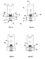
- the Figures 1a and 1b show sectional views of an assembly according to the state of the art for the control of the choice of the length of a fastener.
- the assembly 10 comprises a substantially cylindrical fastening element 11; said element 11 having a head 12, a smooth barrel 13 and a shaped end portion 14, said forming here being crimping grooves.
- the element 11 takes place in a bore of a structural assembly composed of two elements 15, 16 of structure. Said structural assembly is for example part of an aircraft.
- the head 12 is in contact with a first element 15 and the end portion 14 is close to the second structural element 16.
- a crimping ring 17 is then assembled to the shaped end portion 14 to secure the fastening element 11 to the elements 15, 16 of structure.
- a control gauge 18 is then used to verify that the fastener is neither too short nor too long in relation to the assembled structural thickness.
- the gauge 18 comprises a first portion substantially U, comprising two branches 20, 21 substantially symmetrical with respect to an axis 22.
- a regression line D passing through the ends 23, 24 of the two branches is perpendicular to the axis 22. This first part controls that the fastener is not too short.
- the U-shaped portion of the gauge 18 further comprises a central pin 25 disposed between the two branches 20, 21, substantially coaxially with the axis 22.
- a plane passing through one end 26 of the pin and a plane passing through the ends 23, 24 branches 20, 21 are spaced apart by a distance 27 measured along the axis 22, chosen to be a minimum height of protrusion of the fastening element with respect to a theoretical assembled structure thickness.
- the pin 25 is able to slide inside the ring 17, in order to come into contact with a front face 28 of the end portion 14.
- This portion 19 of the gauge 18 is used to verify that the element 11 is not too long compared to the assembled structure thickness.
- This portion 19 comprises a substantially U-shaped portion, comprising two branches 29, 30 substantially symmetrical about the axis 22.
- a central plane portion 31 connects the two branches 29, 30.
- a plane passing through the central plane portion 31 and a plan passing through the ends 32, 33 of the branches 29, 30 are spaced a distance 34 measured along the axis 22, chosen to be a maximum height of exceeding the fixation with respect to a theoretical assembled structure thickness.
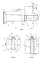
- the figure 3 shows a side view of another fastener 51 according to the state of the art extending along an axis 52.
- the element 51 comprises a countersunk head 53, a frustoconical smooth shaft 54 and a threaded end portion 55 , aligned along the axis 52.
- the front face 56 of the threaded end portion 55 has a cavity 57, disposed parallel to the axis 52 and of substantially cylindrical shape. This cavity 57 keeps the element 51 fixed in rotation by means of a suitable tool, while a nut is installed on the threaded end portion 55.
- the fixing element 51 has a maximum clamping capacity Gmax, which corresponds to the maximum thickness of a structure that said fixing element can assemble.
- This maximum clamping capacity is represented by the length between the end of the element 51 where the head 53 is located, to the limit 61 between the drum 54 and the threaded end portion 55.
- the length Gmax is measured along the axis 52. If the head 53 was a protruding head and not a countersunk head, the length of said head would not be taken into account in the measurement of Gmax.
- the junction zone between the smooth shaft 54 and the threaded end portion 55 is visible in magnified detail on the figure 3 .
- the limit 61 coincides with the beginning of a transition zone, which connects the smooth drum 54 to the first thread F of the threaded end portion 55 by two radii R1 and R2.
- the fixing element 51 has a clamping range P, defined by the manufacturer.
- the minimum clamping capacity Gmin which corresponds to the minimum thickness that a fastener can assemble, is determined by subtracting the clamping range P from the maximum clamping capacity Gmax.
- the bottom 58 of the cavity 57 is situated at a distance 59, measured along the axis 52, from the limit 61.
- the cavity has a depth 60 measured between the bottom 58 of the cavity 57 and the end face 56.
- the depths 60 of the cavities 57 are identical for all fasteners of the same type, regardless of the outside diameter or the length of the element 51.
- FIGS. 4a and 4b show views of fasteners of a family of fasteners according to one embodiment of the invention, installed in a structural assembly.
- Figures 4a and 4b respectively show two fixing elements 101, 121 belonging to the same family of fixing devices.
- Each element 101, 121 extends along an axis 102 and comprises a protruding head 103, a smooth shaft 104 and a shaped end portion 105, aligned along the axis 102.
- the shaping of the end portion 105 is a thread.
- the average outer diameter of the portion 105 is identical for all elements of the family, said average diameter being measured in the middle of the thickness of a net.
- the barrel 104 smooth has an outer surface of frustoconical shape.
- the end face 106 of the shaped end portion 105 has an orifice opening on a cavity 107. Said cavity 107, of substantially cylindrical shape, is disposed parallel to the axis 102, inside the shaped end portion. 105.
- the fixing element 101 has a maximum clamping capacity Gmax. This value corresponds to the length of the smooth shaft 104, measured along the axis 102, from the head 103 to a limit 170 with the threaded end portion 105. The head 103 being protruding, it is not taken into account in the measurement of Gmax.
- the fixing element 101 also has a minimum clamping capacity Gmin and a clamping area P.
- the minimum clamping capacity corresponds to the minimum thickness of a structure that the fixing element 101 can assemble. If the structure has a thickness less than Gmin after clamping a female element on the threaded portion 105, then the element 101 is too long for said structure.
- the value of Gmin is determined by the manufacturer of the fastening elements (101, 121), depending on the mechanical characteristics of said elements.
- the clamping range P corresponds to the difference between Gmax and Gmin.
- the maximum clamping plane Pmax is a plane perpendicular to the axis 102 and passing through the limit 170 between the smooth shaft 104 and the threaded end 105.
- the minimum clamping plane Pmin is a plane parallel to the maximum clamping plane situated between said plane and the head 103, the two planes Pmax and Pmin being separated by a distance P measured along the axis 102 and corresponding to the clamping range.
- the bottom 108 of the cavity 107 is located at a distance 109 'from the maximum clamping plane Pmax, and at a distance 109 from the minimum clamping plane Pmin.
- the difference between the distances 109 'and 109 is the clamping range P of the fastening element 101.
- the cavity 107 has a depth 110 measured between the bottom 108 and the end face 106.
- the element 101 is part of a fastening device which further comprises a bushing 111.
- the bushing 111 has a cylindrical outer surface and a frustoconical inner surface, complementary to the outer surface of the barrel 104.
- the bushing 111 is intended to take placed in a bore formed in elements 112, 113 of structure, which it is desired to assemble. These include structural elements of an aircraft.
- the element 101 is inserted into the bushing 111, so that the head 103 and the threaded end portion 105 are on either side of the structural assembly 114 formed by the elements 112, 113 of structure.
- a nut 115 is then screwed to the end 105 threaded and clamped against a surface 116 of the assembly 114.
- the figure 4b shows a fastening element 121 belonging to the same family as the element 101.
- the above description of the element 101 is applicable to the element 121.
- the elements 101, 121 have different lengths between the head 103 and the front face 106 of the threaded end, as well as lengths Gmax and Gmin different. In this way, they can assemble sets 114 of different thicknesses.
- clamping range P corresponding to (Gmax - Gmin) is the same for all elements (101, 121) of the same family.
- the sockets 111 of the elements 101, 121 have an identical outside diameter 122 and a different internal surface taper ratio.
- the taper ratio of the bushing 111 is a function of the thickness of the structure 114 to be clamped.
- tape ratio is meant in particular an angle formed by an outer surface and an inner surface of the sockets 111, in the plane of section of the Figures 4a and 4b .
- the elements 101, 121 also have different threaded lengths 123 depending on the distance between the head 103 and the face 106. For a given diameter 122, the type elements 101, 121 belonging to the same family may have up to four different taper rates to cover the thickness ranges of structure 114 to be clamped. The family of elements thus has four different threaded lengths 123.
- the elements 101, 121 have an excess length different from the face 106, with respect to the surface 116.
- each element 101, 121 is provided with a cavity 107 whose the depth 110 is calculated so that the bottom 108 is located at a constant distance 109 from the minimum clamping plane Pmin of the fastener, regardless of the length of said element.
- the bottom 108 is also located at a distance 109 'from the maximum clamping plane Pmax, identical for all the elements of the family.
- the distance 109 ' is equal to the distance 109 minus the clamping range P.
- members (101, 121) of the same family having different threaded heights 123 have cavities 107 of different depths 110.
- the distances from the underside of the head 103 to the drilling depth 108 (distance Gmin + 109) can be checked very precisely by means of standard control tools, such as a digital ball screw comparator.
- the invention also applies to fasteners having a cylindrical shaft 104, such elements may or may not be associated with a bushing 111, such as blind rivets or rivets.
- the cavity could be a recess arranged parallel to the axis 102 on the lateral outer surface of the shaped end portion 105.
- the cavity also extends from the end face 106 a distance 110 to a bottom 108, with the difference that said distance 110 is chosen so that the bottom 108 is above the nut or the ring 115 tightened or crimped on the shaped end 105.
- the figure 5 shows a view of an assembly 100 comprising a fastening element 101 as previously described and a control caliber 150.
- the element 101 is part of a fixing device also comprising a nut 115 and a sleeve 111, said device being shown in section.
- Caliber 150 is shown in side view.
- the fixing device comprising the element 101 is installed in a structural assembly 114.
- the function of the caliber 150 is to control the choice of the length of the element 101 after screwing on the nut 115, in particular as a function of the collapse of the assembly 114 during the installation of the fixing device.
- the collapse of the assembly 114 is controlled with respect to the distance 109 between the bottom 108 of the cavity 107 and the minimum clamping plane Pmin of the element 101.
- the caliber 150 is preferably symmetrical about an axis 151 or with respect to a plane passing through said axis.
- the gauge 150 is substantially U-shaped, comprising two branches 152, 153 substantially parallel to the axis 151 and joined by a central portion 154.
- the ends 155, 156 of the two branches are coplanar in a plane perpendicular to the axis 151.
- the central portion 150 of the caliber 150 is integral with a pin 157 disposed between the two branches 152, 153 so that said pin 157 passes through a median plane containing the two branches.
- the pin 157 extends substantially coaxially with the axis 151.
- the pin 157 is dimensioned so as to slide in the cavity 107 formed in the fastening element 101, one end 158 of the pin being able to come into contact with a bottom 108 of said cavity.
- the end 158 of the pin 157 may have different shapes, cone type, tip, ball or flat.
- the bottom 108 of the cavity 107 has a conical shape and the end 158 of the pin is in the form of a ball, said ball shape being well adapted to come into contact with a drilling cone.
- the plane perpendicular to the axis 151 passing through the end 158 of the pin and the plane perpendicular to the axis 151 passing through the ends 155, 156 of the branches 152, 153 are spaced a distance of control 159 measured according to the axis 151.
- the control distance 159 corresponds to a maximum allowed of a distance 109 between the bottom 108 of the cavity 107 of the element 101 and the minimum clamping plane Pmin of the elements 101, 121.
- the gauge is symmetrical with respect to the axis 151 when the cavity is a recess formed inside the shaped end portion 105, as in the example shown in FIG. figure 5 .
- the pin 157 could be shifted to a branch 152 or 153 if the cavity were a hollow formed on an external lateral surface of the shaped end portion 105.
- the gauge could comprise only one only branch if it was used only to control fixtures installed in planar elements, having external surfaces parallel to each other.
- the control distance 159 can be established very precisely during the manufacture of the caliber 150.
- the end 158 in the form of a ball is mounted on the central portion 154 of the caliber, then the branches 152, 153 are ground and adjusted, in particular by grinding, so that the ends 155, 156 are at the desired distance 159 from the end 158 of the pin 157.
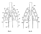
- the figure 6a presents another embodiment of the invention, in the case where the structural assembly 114 has non-parallel surfaces between them. More specifically, the figure 6a is a side view of a caliber 150 used to verify the installation of a fastening device as described above, comprising a cavity 107 in the form of a cylindrical bore in a fastening element 101. The element 101 is installed in a structural assembly 114 having non-parallel surfaces to each other. More precisely, the surface 116 in contact with the female element 115 is not perpendicular to the axis of the element 101.
- figure 6b is a sectional view corresponding to the view 6a. In both figures, the female element 115 is a swivel nut.
- the pin To ensure that the central pin 157 is properly guided in the cavity 107, the pin must have a diameter 160 identical to the cylindrical bore of the cavity 107 - with the clearance, for example between 0.01 mm and 0.03 mm - on a sufficient guide height. This height is for example equal to the greatest depth 110 of the cavity 107 of the longest fastening element (101, 121) of the family. In this way, the central pin has no clearance sufficient to allow it to tilt in the cavity 107. Such inclination could lead to measurement errors.
- the central pin 157 must have a shape complementary to that of the cavity 107 so as to be guided therein with a minimum clearance.
- a groove-like recess 107 formed on a lateral outer surface of the shaped end portion 105 will require a central pin 157 of complementary shape to the groove.
- the figure 7a shows an example of installation of the element 101 in which, in step 3, the ends 155, 156 of the branches 152, 153 of the gauge 150 come into contact with the surface 116 while a set 117, positive or zero , exists between the end 158 of the pin and the bottom 108.
- the total thickness of the assembly 114 is greater than the minimum clamping capacity Gmin of the element 101.
- the minimum clamping plane Pmin passes through the assembly 114.
- the element 101 is not too long and is properly installed.
- figure 7b shows an example of installation of the element 101 in which, in step 3, the end 158 of the pin is in contact with the bottom 108 of the cavity without both ends 155, 156 of the branches of the caliber 150 are in contact with the surface 116.
- the total thickness of the assembly 114 is less than the minimum clamping capacity Gmin of the element.
- the difference in length between the total thickness of the assembly 114 and the minimum clamping capacity Gmin is visually identified by the clearance 119 between the gauge 150 and the structural assembly 114.
- the pin 157 abuts in the bottom 108 of the cavity 107, the ends 155, 156 of the branches of the template pass through the plane Pmin.
- the play 119 is positive, the element 101 is too long, it should be removed and install a shorter one.
- the caliber 150 If only one of the two ends of the caliber 150 touches the structure, then the caliber is poorly positioned: this can happen in the case where the structures to be assembled have a slope, as on the Figures 6a and 6b . The operator must then turn the caliber 150 around the pin axis 151 central 157 so that the ends 155, 156 of the two branches touch the structure 114, or that none touches it. The two cases can not happen simultaneously since the fastener is either well installed or incorrectly installed.
Landscapes
- General Engineering & Computer Science (AREA)
- Engineering & Computer Science (AREA)
- Mechanical Engineering (AREA)
- Physics & Mathematics (AREA)
- General Physics & Mathematics (AREA)
- Insertion Pins And Rivets (AREA)
- Connection Of Plates (AREA)
- Clamps And Clips (AREA)
- Length-Measuring Instruments Using Mechanical Means (AREA)
- Mutual Connection Of Rods And Tubes (AREA)
- Vehicle Body Suspensions (AREA)
- Shafts, Cranks, Connecting Bars, And Related Bearings (AREA)
- Testing Of Devices, Machine Parts, Or Other Structures Thereof (AREA)
- Investigating Strength Of Materials By Application Of Mechanical Stress (AREA)
Description
L'invention se rapporte à une famille de dispositifs de fixation selon le préambule de la revendication 1, ainsi qu'à un procédé d'installation d'un tel dispositif avec contrôle du choix de sa longueur. Une telle famille est connue du document
L'invention trouve une application particulière dans le domaine des fixations filetées, utilisées notamment dans l'industrie aéronautique. Un dispositif de fixation filetée classique comprend un élément de fixation, comme une vis, ladite vis comportant une tête, un fût lisse et une portion d'extrémité filetée. Le dispositif de fixation comprend en outre un élément femelle, comme un écrou présentant un taraudage apte à être vissé sur le filetage de la vis. Le dispositif de fixation peut également comporter une douille ou chemise, dans laquelle s'insère la partie lisse du fût.The invention finds particular application in the field of threaded fasteners, used in particular in the aeronautical industry. A conventional threaded fastener comprises a fastener such as a screw, said screw having a head, a smooth barrel and a threaded end portion. The fixing device further comprises a female element, such as a nut having a tapping adapted to be screwed onto the thread of the screw. The fixing device may also comprise a sleeve or liner in which the smooth part of the barrel is inserted.
Un problème qui se pose couramment est la garantie d'avoir installé correctement le dispositif de fixation sur n'importe quel assemblage de structure préalablement percé. Un procédé d'installation de la fixation peut notamment comprendre les étapes suivantes :
- 1. Choisir la vis de longueur appropriée avant l'installation : la vérification est faite par exemple avec un calibre de mesure d'épaisseur de structure à serrer,
- 2. Préinstaller la vis dans le perçage, en vérifiant que le fût (ou la douille, si la fixation en comporte une) dépasse des structures à assembler,
- 3. Vérifier que la vis choisie n'est pas trop longue par rapport à l'épaisseur une fois serrée, la structure assemblée ayant pu s'affaisser lors de l'installation.
- 1. Choose the screw of appropriate length before installation: the check is made for example with a gauge of thickness of structure to be tightened,
- 2. Pre-install the screw in the hole, checking that the barrel (or socket, if the fastener has one) protrudes from the structures to be assembled,
- 3. Check that the chosen screw is not too long compared to the thickness when tightened, since the assembled structure may have collapsed during installation.
Cette étape doit aussi vérifier que la douille ne touche pas le chambrage de l'écrou si la fixation comprend une telle douille. En effet, dans le cas d'une installation en interférence ― c'est-à-dire sans jeu ― avec le fût de la vis, la douille s'allonge un peu lors de cette installation dans la structure.This step must also verify that the sleeve does not touch the recess of the nut if the attachment comprises such a socket. Indeed, in the case of an installation interference - that is to say without play - with the barrel of the screw, the sleeve extends a little during this installation in the structure.
Pour cette dernière étape de vérification, il existe des calibres de contrôle en forme de plaque prenant appui de part et d'autre de la fixation sur une surface extérieure de la structure à assembler. Ces calibres comportent en leur milieu un évidement ou une forme particulière. Un tel calibre est représenté aux
Un tel calibre permet notamment de détecter visuellement si l'élément de fixation n'est pas trop long par rapport à l'épaisseur serrée, en vérifiant que la longueur filetée reste inférieure à une longueur maximale tolérée de dépassement de la longueur filetée hors de la structure.Such a caliper notably makes it possible to visually detect if the fastener element is not too long compared to the tight thickness, by verifying that the threaded length remains less than a maximum permissible length of exceeding the threaded length outside the structure.
Ce calibre mesure une distance entre une surface frontale de l'extrémité filetée et une surface de la structure. Or lorsque les filets sont réalisés par roulage, l'extrémité filetée s'allonge. Le calibre de contrôle qui s'appuie sur la face frontale d'une extrémité filetée doit alors intégrer l'imprécision de la longueur de fût lisse et l'imprécision de la longueur filetée, qui est peu maîtrisable. L'imprécision totale du système de mesure peut atteindre par exemple +/-0,381 mm.This gauge measures a distance between a front surface of the threaded end and a surface of the structure. But when the nets are made by rolling, the threaded end elongates. The control gauge which rests on the front face of a threaded end must then integrate the inaccuracy of the smooth shank length and the inaccuracy of the threaded length, which is not very controllable. The total inaccuracy of the measuring system can reach for example +/- 0.381 mm.
Dans le cas d'un dispositif de fixation filetée avec douille, le chambrage de l'écrou doit être surdimensionné pour prendre en compte l'imprécision du système de mesure et éviter que la douille ne touche le chambrage lors de son allongement. Une plus grande imprécision de mesure impose donc de concevoir un écrou plus haut, donc plus lourd. Or, un surcroît de poids est à éviter pour des dispositifs destinés à l'industrie aéronautique.In the case of a threaded fastener with socket, the recess of the nut must be oversized to take into account the inaccuracy of the measuring system and prevent the sleeve from touching the recess during its elongation. A greater inaccuracy of measurement therefore requires to design a nut higher, so heavier. However, extra weight is to be avoided for devices intended for the aeronautical industry.
Par ailleurs, le document
L'utilisation d'un calibre usuel comme décrit précédemment imposerait donc d'avoir quatre calibres différents par diamètre, soit par exemple cinquante-deux calibres pour treize diamètres.The use of a standard caliber as described above would therefore require four different calibres per diameter, for example fifty-two calibres for thirteen diameters.
Or, une mise à disposition d'un opérateur d'un trop grand nombre de calibres engendrerait les problèmes suivants :
- ■ Difficulté pour l'opérateur de sélectionner quel calibre utiliser car la longueur de vis, lorsqu'elle est indiquée, est marquée sur la tête de vis alors que le contrôle se fait du côté écrou ;
- ■ Risque de se tromper dans le choix du calibre, et donc de rejeter des fixations bien installées, ou pire, d'accepter des fixations mal installées ;
- ■ Très grand nombre de calibre à concevoir et fabriquer, augmentant d'autant les coûts.
- ■ Difficulty for the operator to select which gauge to use because the screw length, when indicated, is marked on the screw head while the control is on the nut side;
- ■ There is a risk of being wrong in the choice of gauge, and therefore of rejecting well-installed fasteners, or worse, of accepting incorrectly installed fasteners;
- ■ Very large number of templates to design and manufacture, thereby increasing costs.
Un objet de l'invention est de résoudre ces problèmes, ainsi que d'améliorer la précision du calibre, de sorte à rejeter le moins possible de fixations bien installées, tout en rejetant systématiquement les fixations mal installées. Une fixation est dite bien installée quand l'élément femelle (écrou ou bague) installé sur la vis (ou le rivet) est au contact de la structure et qu'aucun contact ne se produit entre l'élément femelle et le fût lisse, ou la douille si le dispositif de fixation en comprend une.An object of the invention is to solve these problems, as well as to improve the accuracy of the caliber, so as to reject the least possible fasteners properly installed, while systematically rejecting the incorrectly installed fasteners. A fastener is said well installed when the female element (nut or ring) installed on the screw (or the rivet) is in contact with the structure and no contact occurs between the female element and the smooth shaft, or the socket if the fixing device includes one.
A cet effet, l'invention se rapporte à une famille de dispositifs de fixation comprenant au moins deux éléments de fixation, chacun desdits éléments s'étendant suivant un premier axe et comprenant une tête, un fût lisse et une portion d'extrémité façonnée alignés, ledit façonnage de la portion d'extrémité consistant en un filetage ou en des gorges de sertissage une face frontale de la portion d'extrémité façonnée présentant une cavité s'étendant parallèlement au premier axe jusqu'à un fond. Les éléments de fixation présentent un même diamètre moyen extérieur d'extrémité façonnée, ledit diamètre moyen étant mesuré au milieu de l'épaisseur d'un filet ou de la profondeur d'une gorge de sertissage. Les éléments de fixation présentant des capacités de serrage maximal différentes, ladite capacité de serrage maximal correspondant à la longueur du fût lisse selon le premier axe entre la tête et une limite entre ledit fût et la portion d'extrémité façonnée. Les éléments de fixation présentent des capacités de serrage minimal différentes, ladite capacité de serrage minimal correspondant à l'épaisseur minimale d'une structure que l'élément de fixation peut assembler. Les éléments de fixation présentent des plages de serrage identiques, une plage de serrage correspondant à la différence entre la capacité de serrage maximal et la capacité de serrage minimal d'un élément de fixation. La famille est configurée de sorte que la distance selon le premier axe entre le fond de la cavité et la limite entre le fût et la portion d'extrémité façonnée est identique pour tous les éléments de fixation.For this purpose, the invention relates to a family of fasteners comprising at least two fastening elements, each of said elements extending along a first axis and comprising a head, a smooth barrel and an aligned shaped end portion. , said forming of the end portion consisting of a thread or crimping grooves a front face of the shaped end portion having a cavity extending parallel to the first axis to a bottom. The fastening elements have the same machined end outer diameter, said average diameter being measured in the middle of the thickness of a thread or the depth of a crimping groove. The fasteners having different maximum clamping capacities, said maximum clamping capacity corresponding to the length of the smooth drum along the first axis between the head and a boundary between said barrel and the shaped end portion. The fastening elements have different minimum clamping capacities, said minimum clamping capacity corresponding to the minimum thickness of a structure that the fastener can assemble. The fasteners have identical clamping ranges, a clamping range corresponding to the difference between the maximum clamping capacity and the minimum clamping capacity of a fastener. The family is configured so that the distance along the first axis between the bottom of the cavity and the boundary between the barrel and the shaped end portion is the same for all fasteners.
Ainsi, il est possible d'utiliser un calibre de contrôle identique pour tous les éléments de la famille, afin de contrôler qu'un élément de fixation a une longueur appropriée à l'épaisseur d'une structure à assembler.Thus, it is possible to use an identical control gauge for all elements of the family, to control that a fastener has a length appropriate to the thickness of a structure to be assembled.
De manière préférentielle, la famille de dispositifs de fixation comprend en outre au moins un élément femelle apte à s'assembler par vissage ou sertissage sur la portion d'extrémité façonnée d'un élément de fixation. L'élément femelle peut être un écrou ou une bague de sertissage.Preferably, the family of fixing devices further comprises at least one female element able to be assembled by screwing or crimping on the shaped end portion of a fastener. The female element may be a nut or a crimping ring.
Selon un mode préférentiel de réalisation de l'invention, la famille de dispositifs de fixation comprend au moins deux éléments de fixation, chaque élément comprenant un fût lisse disposé entre la tête et la portion d'extrémité façonnée, chacun desdits fûts étant tronconique, la famille comprenant en outre au moins deux douilles présentant une surface externe cylindrique et une surface interne tronconique, chacune des surfaces internes étant complémentaire d'une surface d'un fût lisse d'un élément de fixation, les douilles présentant avant mise en interférence un diamètre extérieur identique et un taux de conicité de surface interne différent.According to a preferred embodiment of the invention, the family of fasteners comprises at least two fastening elements, each element comprising a smooth shaft disposed between the head and the shaped end portion, each of said barrels being frustoconical, the family further comprising at least two sockets having a cylindrical outer surface and a frustoconical inner surface, each of the inner surfaces being complementary to a surface of a smooth shank of a fastener, the sockets having a diameter prior to interference identical exterior and a different internal surface taper ratio.
Cette famille de dispositifs de fixation est analogue à la famille décrite dans le document
Préférentiellement, sur la face frontale de la portion d'extrémité façonnée du ou des éléments de fixation, la cavité présente un bord périphérique en forme de ligne courbe continue multilobée. Une telle forme, notamment décrite dans la demande de brevet français n°
L'invention met également en oeuvre un calibre de contrôle comportant un élément mâle qui coopère avec la cavité située sur la portion d'extrémité façonnée d'un élément de fixation d'une famille selon l'invention. Il est possible de contrôler la profondeur de cette cavité de manière beaucoup plus précise que la longueur filetée car cette cavité est usinée après roulage des filets ou des gorges, et sa réalisation est maîtrisable avec une précision très supérieure à celle du roulage des filets ou des gorges.The invention also uses a control gauge comprising a male element which cooperates with the cavity located on the shaped end portion of a family fastening element according to the invention. It is possible to control the depth of this cavity in a much more precise manner than the threaded length because this cavity is machined after rolling nets or grooves, and its realization is controllable with a much higher accuracy than the rolling of the nets or the threads. gorges.
L'invention se rapporte également à un ensemble pour installation d'un dispositif de fixation, comprenant :
- un calibre de contrôle ayant une forme sensiblement en U, comprenant deux branches sensiblement symétriques par rapport à un deuxième axe et réunies par une partie centrale, les extrémités des deux branches étant coplanaires selon un plan perpendiculaire audit deuxième axe,
- une famille de dispositifs de fixations telle que décrite précédemment.
- a control gauge having a substantially U-shaped shape, comprising two branches substantially symmetrical with respect to a second axis and joined by a central part, the ends of the two branches being coplanar in a plane perpendicular to said second axis,
- a family of fastening devices as described previously.
L'ensemble est caractérisé en ce que :
- la partie centrale du calibre est solidaire d'un picot apte à coulisser dans la cavité de l'élément de fixation, ledit picot étant disposé entre les deux branches du U, sensiblement parallèlement au deuxième axe, une extrémité du picot et le plan passant par les extrémités des branches étant éloignés d'une distance de contrôle mesurée selon ledit deuxième axe,
- la distance de contrôle est supérieure à une distance selon le premier axe entre le fond de la cavité de l'élément de fixation et la limite entre le fût et la portion d'extrémité façonnée.
- the central portion of the gauge is secured to a pin capable of sliding in the cavity of the fastening element, said pin being disposed between the two branches of the U, substantially parallel to the second axis, one end of the pin and the plane passing through the ends of the branches being away from a measured control distance along said second axis,
- the control distance is greater than a distance along the first axis between the bottom of the cavity of the fastener and the boundary between the barrel and the shaped end portion.
Un tel ensemble permet une conception plus précise du calibre. Par ailleurs, la cavité ménagée dans l'élément de fixation permet de réduire la masse de ce dernier et de l'élément femelle par rapport aux dispositifs connus, ce qui est particulièrement avantageux dans le domaine aéronautique.Such an assembly allows a more precise design of the caliber. Furthermore, the cavity in the fastener element reduces the mass of the latter and the female element relative to known devices, which is particularly advantageous in the aeronautical field.
L'invention se rapporte en outre à un procédé de contrôle du choix de la longueur d'un élément de fixation, mettant en oeuvre un ensemble tel que décrit ci-dessus, ledit procédé comportant les étapes suivantes :
- insertion d'un élément de fixation dans un alésage d'un ensemble structural, de manière à ce que la tête et la portion d'extrémité façonnée dudit élément soient disposées de part et d'autre dudit ensemble structural,
- assemblage de l'élément femelle avec la portion d'extrémité façonnée et serrage de l'élément femelle contre une surface de l'ensemble structural,
- insertion du picot du calibre de contrôle dans la cavité de la portion d'extrémité façonnée, afin de mettre en contact l'extrémité du picot et un fond de la cavité,
- si l'extrémité du picot est en contact avec le fond de la cavité sans que les extrémités des deux branches du calibre ne puissent être au contact de la surface de l'ensemble structural, alors l'élément de fixation est trop long.
- inserting a fastener into a bore of a structural assembly, such that the head and the shaped end portion of said member are disposed on either side of said structural assembly;
- assembling the female member with the shaped end portion and clamping the female member against a surface of the structural assembly,
- insertion of the control gauge pin into the cavity of the shaped end portion to contact the end of the pin and a bottom of the cavity;
- if the end of the pin is in contact with the bottom of the cavity without the ends of the two branches of the template can not be in contact with the surface of the structural assembly, then the fastener is too long.
L'invention sera mieux comprise à la lecture de la description qui suit et à l'examen des figures qui l'accompagnent. Celles-ci sont données à titre indicatif et nullement limitatif de l'invention. Les figures montrent :
-
Figures 1a, 1b : des vues en coupe d'un ensemble selon l'état de la technique pour un premier contrôle du choix de longueur d'un élément de fixation installé dans une structure; -
Figures 2a, 2b : des vues en coupe d'un ensemble selon l'état de la technique pour un deuxième contrôle du choix de longueur d'un élément de fixation installé dans une structure; -
Figure 3 : une vue latérale d'un autre élément de fixation selon l'état de la technique; -
Figures 4a, 4b : des vues en coupe d'éléments de fixation d'une famille d'éléments de fixation selon un mode de réalisation de l'invention ; -
Figure 5 : une vue en coupe d'éléments d'un ensemble pour le contrôle du choix de la longueur d'un élément de fixation selon un mode de réalisation de l'invention ; -
Figures 6a, 6b : des vues en coupe d'éléments d'un ensemble pour le contrôle du choix de la longueur d'un élément de fixation installé dans une structure en pente, selon un mode de réalisation de l'invention ; -
Figures 7a, 7b : des vues en coupe d'éléments d'un ensemble pour le contrôle du choix de la longueur d'un élément de fixation selon un mode de réalisation de l'invention.
-
Figures 1a, 1b : Sectional views of a set according to the state of the art for a first control of the choice of length of a fastener installed in a structure; -
Figures 2a, 2b : Sectional views of an assembly according to the state of the art for a second control of the choice of length of a fastener installed in a structure; -
Figure 3 : a side view of another fastener according to the state of the art; -
Figures 4a, 4b : sectional views of fasteners of a family of fasteners according to one embodiment of the invention; -
Figure 5 : a sectional view of elements of an assembly for controlling the choice of the length of a fastener according to one embodiment of the invention; -
Figures 6a, 6b : sectional views of elements of an assembly for controlling the choice of the length of a fastener installed in a sloping structure, according to one embodiment of the invention; -
Figures 7a, 7b : sectional views of elements of an assembly for controlling the choice of the length of a fastener according to one embodiment of the invention.
Les
La tête 12 se trouve au contact d'un premier élément 15 et la portion d'extrémité 14 est proche du second élément 16 de structure. Une bague 17 de sertissage est ensuite assemblée à la portion d'extrémité façonnée 14 pour solidariser l'élément 11 de fixation aux éléments 15, 16 de structure.The
Un calibre 18 de contrôle est ensuite utilisé afin de vérifier que l'élément de fixation n'est ni trop court ni trop long par rapport à l'épaisseur de structure assemblée. A cet effet, le calibre 18 comporte une première partie sensiblement en U, comprenant deux branches 20, 21 sensiblement symétriques par rapport à un axe 22. Une droite de régression D passant par les extrémités 23, 24 des deux branches est perpendiculaire à l'axe 22. Cette première partie contrôle que l'élément de fixation n'est pas trop court.A
La partie en U du calibre 18 comprend en outre un picot 25 central disposé entre les deux branches 20, 21, sensiblement coaxialement à l'axe 22. Un plan passant par une extrémité 26 du picot et un plan passant par les extrémités 23, 24 des branches 20, 21 sont éloignés d'une distance 27 mesurée selon l'axe 22, choisie comme étant une hauteur minimale de dépassement de l'élément de fixation par rapport à une épaisseur de structure assemblée théorique. Le picot 25 est apte à coulisser à l'intérieur de la bague 17, afin d'entrer en contact avec une face 28 frontale de la portion d'extrémité 14.The U-shaped portion of the
Sur la
Sur la
Une autre partie 19 du calibre 18 est utilisée pour vérifier que l'élément 11 n'est pas trop long par rapport à l'épaisseur de structure assemblée. Cette partie 19 comprend une partie sensiblement en U, comprenant deux branches 29, 30 sensiblement symétriques par rapport à l'axe 22. Une partie plane médiane 31 relie les deux branches 29, 30. Un plan passant par la partie plane médiane 31 et un plan passant par les extrémités 32, 33 des branches 29, 30 sont éloignés d'une distance 34 mesurée selon l'axe 22, choisie comme étant une hauteur maximale de dépassement de la fixation par rapport à une épaisseur de structure assemblée théorique.Another
Sur la
Sur la
La
L'élément 51 de fixation présente une capacité maximale de serrage Gmax, qui correspond à l'épaisseur maximale d'une structure que ledit élément de fixation peut assembler. Cette capacité maximale de serrage est représentée par la longueur comprise entre l'extrémité de l'élément 51 où se trouve la tête 53, jusqu'à la limite 61 entre le fût 54 et la portion 55 d'extrémité filetée. La longueur Gmax est mesurée selon l'axe 52. Si la tête 53 était une tête protubérante et non une tête fraisée, la longueur de ladite tête ne serait pas prise en compte dans la mesure de Gmax.The fixing
La zone de jonction entre le fût lisse 54 et la portion 55 d'extrémité filetée est visible en détail magnifié sur la
Le fond 58 de la cavité 57 est situé à une distance 59, mesurée selon l'axe 52, de la limite 61. La cavité présente une profondeur 60 mesurée entre le fond 58 de cavité 57 et la face frontale 56. Les profondeurs 60 des cavités 57 sont identiques pour tous les éléments de fixation d'un même type, quelle que soit le diamètre extérieur ou la longueur de l'élément 51.The bottom 58 of the
Les
Plus particulièrement, les
L'élément 101 de fixation présente une capacité maximale de serrage Gmax. Cette valeur correspond à la longueur du fût 104 lisse, mesurée selon l'axe 102, depuis la tête 103 jusqu'à une limite 170 avec la portion 105 d'extrémité filetée. La tête 103 étant protubérante, elle n'est pas prise en compte dans la mesure de Gmax.The fixing
L'élément 101 de fixation présente également une capacité minimale de serrage Gmin et une plage de serrage P. La capacité minimale de serrage correspond à l'épaisseur minimale d'une structure que l'élément 101 de fixation peut assembler. Si la structure a une épaisseur inférieure à Gmin après serrage d'un élément femelle sur la portion 105 filetée, alors l'élément 101 est trop long pour ladite structure.The fixing
La valeur de Gmin est déterminée par le fabricant des éléments (101, 121) de fixation, en fonction des caractéristiques mécaniques desdits éléments. La plage de serrage P correspond à la différence entre Gmax et Gmin.The value of Gmin is determined by the manufacturer of the fastening elements (101, 121), depending on the mechanical characteristics of said elements. The clamping range P corresponds to the difference between Gmax and Gmin.
On dénomme plan de serrage maximal Pmax un plan perpendiculaire à l'axe 102 et passant par la limite 170 entre le fût 104 lisse et l'extrémité 105 filetée. On dénomme plan de serrage minimal Pmin un plan parallèle au plan de serrage maximal, situé entre ledit plan et la tête 103, les deux plans Pmax et Pmin étant écartés d'une distance P mesurée selon l'axe 102 et correspondant à la plage de serrage.The maximum clamping plane Pmax is a plane perpendicular to the
Le fond 108 de la cavité 107 est situé à une distance 109' du plan de serrage maximal Pmax, et à une distance 109 du plan de serrage minimal Pmin. La différence entre les distance 109' et 109 est la plage de serrage P de l'élément 101 de fixation. La cavité 107 présente une profondeur 110 mesurée entre le fond 108 et la face frontale 106.The
L'élément 101 fait partie d'un dispositif de fixation qui comprend en outre une douille 111. La douille 111 possède une surface externe cylindrique et une surface interne tronconique, complémentaire de la surface externe du fût 104. La douille 111 est destinée à prendre place dans un alésage ménagé dans des éléments 112, 113 de structure, que l'on souhaite assembler. Il s'agit notamment d'éléments de structure d'un aéronef.The
L'élément 101 vient s'insérer dans la douille 111, de manière à ce que la tête 103 et la portion d'extrémité 105 filetée se trouvent de part et d'autre de l'ensemble structural 114 formé par les éléments 112, 113 de structure. Un écrou 115 est ensuite vissé à l'extrémité 105 filetée et serré contre une surface 116 de l'ensemble 114.The
Sur les
Afin de répondre aux exigences de tenue mécanique requises en aéronautique, il convient de vérifier, suite à l'installation de l'écrou, que ce dernier est convenablement installé. Il faut également vérifier que la fixation n'est pas trop longue par rapport à l'épaisseur serrée, ou en d'autres termes, vérifier que l'épaisseur serrée ne se trouve pas en-deçà de la plage de serrage minimale Gmin de l'élément de fixation choisi. En effet, une fixation trop longue par rapport à la structure assemblée n'est pas correctement installée, soit parce que l'écrou 115 ne touche pas la surface 116 de l'ensemble 114, soit parce que l'extrémité de la douille 111 tape dans le chambrage de l'écrou.In order to meet the requirements of mechanical strength required in aeronautics, it must be verified, following the installation of the nut, that the latter is properly installed. It should also be checked that the fastening is not too long compared to the tight thickness, or in other words, check that the tight thickness is not below the minimum clamping range Gmin of the chosen fastening element. Indeed, a fixation too long compared to the assembled structure is not correctly installed, either because the
La
Les éléments 101, 121 présentent des longueurs différentes entre la tête 103 et la face 106 frontale de l'extrémité filetée, ainsi que des longueurs Gmax et Gmin différentes. De cette manière, ils peuvent assembler des ensembles 114 d'épaisseurs différentes.The
Cependant, la plage de serrage P, correspondant à (Gmax ― Gmin), est la même pour tous les éléments (101, 121) d'une même famille.However, the clamping range P corresponding to (Gmax - Gmin) is the same for all elements (101, 121) of the same family.
Par ailleurs, les douilles 111 des éléments 101, 121 présentent un diamètre 122 extérieur identique et un taux de conicité de surface intérieur différent. Le taux de conicité de la douille 111 est fonction de l'épaisseur de structure 114 à serrer. Par « taux de conicité », on entend notamment un angle formé par une surface externe et une surface interne des douilles 111, dans le plan de coupe des
Les éléments 101, 121 présentent également des longueurs 123 filetées différentes en fonction de la distance entre la tête 103 et la face 106 frontale. Pour un diamètre 122 donné, les éléments de type 101, 121 appartenant à une même famille peuvent présenter jusqu'à quatre taux de conicité différents pour couvrir les plages d'épaisseur de structure 114 à serrer. La famille d'éléments présente ainsi quatre longueurs 123 filetées différentes.The
En conséquence, pour une fixation conforme aux exigences requises, les éléments 101, 121 présentent une longueur de dépassement différente de la face 106, par rapport à la surface 116.Consequently, for a fastening according to the required requirements, the
Cependant, comme indiqué précédemment, il est préférable de pouvoir utiliser un seul et même calibre de contrôle pour vérifier que le choix de la longueur de l'élément de fixation reste correct après installation, pour la totalité des éléments d'une même famille.However, as indicated above, it is preferable to be able to use one and the same control gauge to check that the choice of the length of the fastener remains correct after installation, for all elements of the same family.
Ainsi, afin de n'utiliser qu'un seul calibre de contrôle pour toute une famille d'éléments (101, 121) de même diamètre extérieur moyen d'extrémités 105 filetées, chaque élément 101, 121 est muni d'une cavité 107 dont la profondeur 110 est calculée de sorte que le fond 108 est situé à une distance 109 constante du plan de serrage minimal Pmin de l'élément de fixation, quelle que soit la longueur dudit élément.Thus, in order to use only one control gauge for a whole family of elements (101, 121) having the same mean outer diameter of threaded ends 105, each
Comme la plage de serrage P d'une fixation est identique pour tous les éléments (101, 121) d'une même famille, le fond 108 est aussi situé à une distance 109' du plan de serrage maximal Pmax, identique pour tous les éléments de la famille. La distance 109' est égale à la distance 109 moins la plage de serrage P.As the clamping range P of a fastener is identical for all the elements (101, 121) of the same family, the bottom 108 is also located at a distance 109 'from the maximum clamping plane Pmax, identical for all the elements of the family. The distance 109 'is equal to the
Ainsi, des éléments (101, 121) d'une même famille possédant des hauteurs 123 filetées différentes ont des cavités 107 de profondeur 110 différentes. Les distances depuis le dessous de la tête 103 jusqu'au fond 108 de perçage (distance Gmin + 109) peuvent être vérifiées très précisément au moyen d'outils de contrôle usuels, tels qu'un comparateur digital à touche sphérique.Thus, members (101, 121) of the same family having different threaded
L'invention s'applique également à des éléments de fixation ayant un fût 104 de forme cylindrique, de tels éléments pouvant ou non être associés à une douille 111, comme par exemple des rivets ou des rivets aveugles.The invention also applies to fasteners having a
Selon une variante de l'invention, la cavité pourrait être un creux disposé parallèlement à l'axe 102 sur la surface extérieure latérale de la portion 105 d'extrémité façonnée. La cavité s'étend également depuis la face frontale 106 sur une distance 110 jusqu'à un fond 108, à la différence que ladite distance 110 est choisie de manière à ce que le fond 108 se trouve au-dessus de l'écrou ou de la bague 115 serré ou sertie sur l'extrémité façonnée 105.According to a variant of the invention, the cavity could be a recess arranged parallel to the
La
Le dispositif de fixation comprenant l'élément 101 est installé dans un ensemble 114 structural. Le calibre 150 a pour fonction de contrôler le choix de la longueur de l'élément 101 après vissage de l'écrou 115, notamment en fonction de l'affaissement de l'ensemble 114 durant l'installation du dispositif de fixation.The fixing device comprising the
L'affaissement de l'ensemble 114 est contrôlé par rapport à la distance 109 séparant le fond 108 de la cavité 107 et le plan de serrage minimal Pmin de l'élément 101.The collapse of the
Le calibre 150 est préférentiellement symétrique par rapport à un axe 151 ou par rapport à un plan passant par ledit axe. Le calibre 150 a une forme sensiblement en U, comprenant deux branches 152, 153 sensiblement parallèles à l'axe 151 et réunies par une partie 154 centrale. Les extrémités 155, 156 des deux branches sont coplanaires selon un plan perpendiculaire à l'axe 151.The
La partie 154 centrale du calibre 150 est solidaire d'un picot 157, disposé entre les deux branches 152, 153 de sorte que ledit picot 157 passe par un plan médian contenant les deux branches. Le picot 157 s'étend sensiblement coaxialement à l'axe 151. Le picot 157 est dimensionné de manière à pouvoir coulisser dans la cavité 107 ménagée dans l'élément 101 de fixation, une extrémité 158 du picot pouvant entrer en contact avec un fond 108 de ladite cavité.The
L'extrémité 158 du picot 157 peut avoir des formes différentes, de type cône, pointe, bille ou plat. De manière préférentielle, le fond 108 de la cavité 107 a une forme conique et l'extrémité 158 du picot a la forme d'une bille, ladite forme de bille étant bien adaptée pour entrer en contact avec un cône de perçage.The
Le plan perpendiculaire à l'axe 151 passant par l'extrémité 158 du picot et le plan perpendiculaire à l'axe 151 passant par les extrémités 155, 156 des branches 152, 153 sont éloignés d'une distance de contrôle 159 mesurée selon l'axe 151. La distance de contrôle 159 correspond à un maximum autorisé d'une distance 109 entre le fond 108 de la cavité 107 de l'élément 101 et le plan de serrage minimal Pmin des éléments 101, 121.The plane perpendicular to the axis 151 passing through the
Le calibre est symétrique par rapport à l'axe 151 lorsque la cavité est un creux pratiqué à l'intérieur de la portion d'extrémité façonnée 105, comme dans l'exemple représenté à la
La distance de contrôle 159 peut être établie de manière très précise lors de la fabrication du calibre 150. Par exemple, l'extrémité 158 en forme de bille est montée sur la partie 154 centrale du calibre, puis les branches 152, 153 sont rectifiées et ajustées, notamment par meulage, afin que les extrémités 155, 156 soient à la distance 159 souhaitée de l'extrémité 158 du picot 157.The
La
Pour s'assurer que le picot central 157 est correctement guidé dans la cavité 107, le picot doit avoir un diamètre 160 identique au perçage cylindrique de la cavité 107 - au jeu près, par exemple entre 0,01 mm et 0,03 mm - sur une hauteur de guidage suffisante. Cette hauteur est par exemple égale à la plus grande profondeur 110 de la cavité 107 de l'élément de fixation (101, 121) le plus long de la famille. De cette manière, le picot central ne possède aucun jeu suffisant lui permettant de s'incliner dans la cavité 107. Une telle inclinaison pourrait entraîner des erreurs de mesure.To ensure that the
D'une manière générale, le picot central 157 doit avoir une forme complémentaire à celle de la cavité 107 de sorte à être guidé dans celle-ci avec un jeu minimum. Ainsi, une cavité 107 en forme de rainure pratiquée sur une surface extérieure latérale de la portion d'extrémité façonnée 105 nécessitera un picot central 157 de forme complémentaire à la rainure.In general, the
Un procédé d'installation d'un dispositif de fixation, mettant en oeuvre un ensemble tel que l'ensemble 100, comporte par exemple les étapes suivantes :
- Etape 1 : insertion d'un élément (101, 121) de fixation dans un alésage d'un
ensemble 114 structural, de manière à ce que la tête 103et l'extrémité 105 filetée dudit élément soient disposées de part et d'autre duditensemble 114 structural. L'opérateur vérifie visuellement que la douille 111, ou le fut lisse 104 si la fixation ne possède pas de douille, dépasse de lastructure 114. De cette manière, il vérifie visuellement que l'épaisseur de structure à assembler n'est pas supérieure à la capacité de serrage maximale Gmax de l'élément de fixation (101, 121) choisi. Si la douille 111 ou le fût lisse 104 ne dépasse pas de l'alésage, l'élément de fixation est trop court et l'opérateur doit en choisir un autre plus long. - Etape 2 : assemblage de l'écrou 115 avec la
portion d'extrémité 105 filetée et serrage de l'écrou contre lasurface 116 de l'ensemble 114 structural. L'invention s'applique également à des éléments de fixation ayant des gorges de sertissage sur l'extrémité 105, l'écrou 115 étant alors remplacé par une bague de sertissage. - Etape 3 : insertion du picot 157 du
calibre 150 de contrôle dans la cavité 107 de laportion d'extrémité 105 filetée. Cette étape permet de vérifier que l'épaisseur de structure à assembler une fois serrée ne s'est pas affaissée et ne se trouve pas en dessous de la capacité minimale de serrage Gmin de l'élément defixation
- Step 1: insertion of a fixing element (101, 121) in a bore of a
structural assembly 114, so that thehead 103 and the threadedend 105 of said element are disposed on either side of said 114 structural assembly. The operator visually verifies that thesleeve 111, or was smooth 104 if the fastener does not have a bushing, protrudes from thestructure 114. In this way, it visually verifies that the thickness of the structure to be assembled is not greater than to the maximum clamping capacity Gmax of the selected fastening element (101, 121). If thebushing 111 or thesmooth drum 104 does not protrude from the bore, the fastener is too short and the operator must choose a longer one. - Step 2: assembling the
nut 115 with the threadedend portion 105 and tightening the nut against thesurface 116 of thestructural assembly 114. The invention also applies to fastening elements having crimping grooves on theend 105, thenut 115 then being replaced by a crimping ring. - Step 3: insertion of the
control gauge 150pin 157 into thecavity 107 of the threadedend portion 105. This step makes it possible to verify that the thickness of structure to be assembled once tightened has not sagged and is not below the minimum clamping capacity Gmin of thefastening element
La
Dans ce cas, l'épaisseur totale de l'ensemble 114 est supérieure à la capacité minimale de serrage Gmin de l'élément 101. En d'autres termes, le plan Pmin de serrage minimal passe par l'ensemble 114. L'élément 101 n'est pas trop long et est convenablement installé.In this case, the total thickness of the
Au contraire, la
Si seule une des deux extrémités du calibre 150 touche la structure, alors le calibre est mal positionné : cela peut arriver dans le cas où les structures à assembler présentent une pente, comme sur les
Il est avantageux de prévoir, sur le calibre 150, des inscriptions de type TOUCH-GO ou NO TOUCH-NO GO au niveau des branches 152, 153, qui donnent à l'opérateur une indication du résultat à déterminer à l'étape 3.It is advantageous to provide, on the
Claims (13)
- Family of fastening devices including at least two fastening elements (101, 121), each one of said elements extending according to a first axis (102) and including a head (103), a smooth body (104) and a shaped end portion (105) which are aligned, said shaping of the end portion consisting in providing a thread or crimping grooves, the fastening elements being provided with shaped ends having identical average external diameters, said family being characterized in that:- a frontal face (106) of the shaped end portion (105) of each of the fastening elements has a cavity (107) extending parallel to the first axis (102) as far as a bottom (108),- the fastening elements have different maximum tightening capacities (Gmax), said maximum tightening capacity corresponding to the length of the smooth body (104) according to the first axis (102) between the head (103) and the limit (170) between said body and the shaped end portion (105),- the fastening elements have different minimal tightening capacities (Gmin), said minimal tightening capacity corresponding to the minimal thickness of a structure the fastening element can assemble,- the fastening elements have identical tightening ranges (P), a tightening range corresponding to the difference between the maximal tightening capacity (Gmax) and the minimal tightening capacity (Gmin) of a fastening element,the family being configured so that the distance (109') according to the first axis (102) between the bottom (108) of the cavity (107) and the limit (170) between the body and the shaped end portion is identical for all the fastening elements (101, 121).
- Family of fastening devices according to claim 1, including moreover at least one female element (115) able to be assembled onto a machined end of a fastening element by screwing or crimping.
- Family of fastening devices according to claim 1 or claim 2, including moreover at least one bush (111) intended to fit around the smooth body (104) of a fastening element.
- Family of fastening devices according to any one of the preceding claims, wherein the smooth body (104) is truncated.
- Family of fastening devices according to claim 4, including moreover at least two bushes (111) having a cylindrical external surface and a truncated internal surface, each of the internal surfaces being complementary to a surface of a smooth body (104) of a fastening element, the bushes having before the interference identical external diameters and different amounts of internal surface taper.
- Family of fastening devices according to any one of the preceding claims, wherein the cavity (107) is a cylindrical bore in the shaped end portion (105).
- Family of fastening devices according to claim 6, wherein the cavity (107) has a peripheral edge in the form of multilobed continuous curved line.
- Family of fastening devices according to any one of claims 1 to 5, wherein the cavity (107) is a recess in the external surface on the shaped end portion(s) (105).
- Unit (100) for installing a fastening device, including:- at least one check gauge (150) having substantially a U-shape, including two branches (152, 153). substantially symmetrical relative to a second axis (151) and joined together by a central part (154), the ends (155, 156) of the two branches being coplanar in a plane perpendicular to said second axis,- a family of fastening devices according to anyone of the preceding claims,the unit being characterized in that:- the central part of the gauge is integral with a pin (157) able to slide in the cavity (107) of the fastening element (101, 121), said pin being arranged between the two branches (152, 153) of the U, substantially parallel to the second axis (151), one end (158) of the pin and the plane extending through the ends (155, 156) of the branches being distant from one another by a check distance (159) measured according to said second axis,- the check distance (159) is higher than a distance (109') according to the first axis (102) between the bottom (108) of the cavity (107)' and the limit (170) between the body and the shaped end portion.
- Unit according to claim 9, wherein the end (158) of the pin (157) is ball-shaped.
- Unit according to claim 10, wherein the pin (157) has a shape (160) complementary to that of the cavity (107) over a guiding height extending over at least a part of the length of the pin.
- Unit according to claim 11, wherein the pin (157) has a guiding height equal to the greatest depth (110) of the cavity (107) of the longest fastening element (101, 121) of the family.
- Method for checking the choice of the length of a fastening element, implementing a unit (100) according to any one of the claims 9 to 12, comprising a family of fastening devices according to any one of the claims 2 to 8, said method comprising the following steps of:- inserting a fastening element (101, 121) into a bore in a structural unit (114), so that the head (103) and the shaped end portion (105) of said element are arranged on both sides of said structural unit,- assembling the female element (115) on the shaped end portion (105) and tightening the female element against a surface (116) of the structural unit,- inserting the pin (157) of the check gauge (150) into the cavity (107) in the shaped end portion,- if the end of the pin is in contact with the bottom (108) of the cavity without the ends (155, 156) of both branches of the gauge being able to be in contact with the surface (116) of the structural unit, then the fastening element is too long.
Applications Claiming Priority (1)
| Application Number | Priority Date | Filing Date | Title |
|---|---|---|---|
| FR1150951A FR2971306B1 (en) | 2011-02-07 | 2011-02-07 | FAMILY OF FIXING ELEMENTS, CONTROL SIZE AND METHOD OF CHECKING THE LENGTH CHOICE OF A FASTENING MEMBER |
Publications (2)
| Publication Number | Publication Date |
|---|---|
| EP2484921A1 EP2484921A1 (en) | 2012-08-08 |
| EP2484921B1 true EP2484921B1 (en) | 2013-08-21 |
Family
ID=44303369
Family Applications (1)
| Application Number | Title | Priority Date | Filing Date |
|---|---|---|---|
| EP12150869.1A Active EP2484921B1 (en) | 2011-02-07 | 2012-01-12 | Group of attachment elements, testing gauge and method for checking the choice of the length of an attachment element |
Country Status (17)
| Country | Link |
|---|---|
| US (1) | US8926248B2 (en) |
| EP (1) | EP2484921B1 (en) |
| JP (1) | JP6004661B2 (en) |
| KR (1) | KR101354349B1 (en) |
| CN (1) | CN102628468B (en) |
| AU (1) | AU2012200228B2 (en) |
| BR (1) | BR102012002794A2 (en) |
| CA (1) | CA2765955C (en) |
| ES (1) | ES2435317T3 (en) |
| FR (1) | FR2971306B1 (en) |
| IL (1) | IL217454A0 (en) |
| IN (1) | IN2012DE00123A (en) |
| MA (1) | MA34043B1 (en) |
| MX (1) | MX2012001540A (en) |
| RU (1) | RU2500930C2 (en) |
| TW (1) | TW201248025A (en) |
| ZA (1) | ZA201200504B (en) |
Families Citing this family (8)
| Publication number | Priority date | Publication date | Assignee | Title |
|---|---|---|---|---|
| CN105091708B (en) * | 2015-06-06 | 2017-10-17 | 台州广播电视大学 | A kind of detection method of axle position length |
| CN108071655A (en) * | 2016-11-16 | 2018-05-25 | 孙愉后 | Indicate the fastener of the loose amount of moving back |
| US10845179B2 (en) * | 2018-10-29 | 2020-11-24 | The Boeing Company | Gauge tool for determining blind fastener length |
| JP2020133861A (en) * | 2019-02-25 | 2020-08-31 | 三菱重工業株式会社 | Fastening method and fastening device |
| CN109974552A (en) * | 2019-03-28 | 2019-07-05 | 承德钢铁集团有限公司 | A kind of spiral cross rib height detection tool and the method for inspection |
| GB2582940B (en) * | 2019-04-09 | 2021-04-07 | Star Fasteners Uk Ltd | Swaged fasteners |
| WO2020261606A1 (en) * | 2019-06-25 | 2020-12-30 | 株式会社松尾工業所 | Fastening structure for object to be fastened, and bolt hole structure |
| CN114406040B (en) * | 2021-12-03 | 2023-04-11 | 株洲硬质合金集团有限公司 | Tooth-like hard alloy counter bore die product pressing position control method |
Family Cites Families (37)
| Publication number | Priority date | Publication date | Assignee | Title |
|---|---|---|---|---|
| FR1059674A (en) | 1952-07-11 | 1954-03-26 | Advanced weft cutter templet for automatic looms | |
| NL104141C (en) * | 1957-02-28 | |||
| US2897867A (en) * | 1957-05-06 | 1959-08-04 | Torre Joseph La | Lock nut having pivoting concave bearing end and inwardly deformed tip to effectuate uniformly stressed threads |
| JPS482906Y1 (en) * | 1970-07-02 | 1973-01-25 | ||
| JPS5214844Y2 (en) * | 1973-11-14 | 1977-04-04 | ||
| US3915052A (en) * | 1974-08-22 | 1975-10-28 | Huck Mfg Co | Self broaching fastener assembly and like self sizing fasteners |
| US4048898A (en) * | 1974-10-17 | 1977-09-20 | Paul R. Briles | Fastener for multi metal stack-ups |
| US4260005A (en) | 1977-11-09 | 1981-04-07 | Vsi Corporation | Self-locking fastener, fastener system, and process |
| US4544312A (en) * | 1981-03-17 | 1985-10-01 | Vsi Corporation | Pin and process for its manufacture |
| JPS61173825U (en) * | 1985-04-18 | 1986-10-29 | ||
| DE3665908D1 (en) * | 1985-04-29 | 1989-11-02 | Huck Mfg Co | Variable clamp fastener and method of using same for securing workpieces together |
| US4874275A (en) * | 1987-06-22 | 1989-10-17 | Gene W. Arant | Secure three-piece threaded fastener, and method |
| JPH01158207A (en) * | 1987-12-15 | 1989-06-21 | Daifuku Co Ltd | Bolt nut |
| DE69020153T2 (en) * | 1989-05-31 | 1995-11-16 | Huck Int Inc | FASTENING SYSTEM CONSISTING OF A FASTENING ELEMENT AND A PRIMED COLLAR AND TOOL FOR INSTALLING THE SYSTEM. |
| JPH0446326Y2 (en) * | 1989-08-01 | 1992-10-30 | ||
| JPH0592511U (en) * | 1992-05-15 | 1993-12-17 | 河西工業株式会社 | Item fixing structure |
| GB2283293A (en) * | 1993-10-29 | 1995-05-03 | Avdel Systems Ltd | Dual-function fastener and method of use |
| US5439339A (en) * | 1993-12-01 | 1995-08-08 | Hi-Shear Corporation | Externally threaded interference fit fastener with oppositely threaded puller |
| JPH09310713A (en) * | 1996-05-22 | 1997-12-02 | Mitsubishi Heavy Ind Ltd | Bolt fastening joint |
| EP0947716A3 (en) * | 1998-04-03 | 2000-08-23 | Fairchild Holding Corp. | Fastener system with cross-slot recess and cross-slot bit |
| US6233802B1 (en) * | 1999-08-06 | 2001-05-22 | Huck International, Inc. | Low swage load fastener and fastening system |
| US6290445B1 (en) * | 2000-04-18 | 2001-09-18 | Avibank Mfg., Inc. | Non-removable structural threaded fastener with threads of lesser outer diameter than the shank and method of forming same |
| KR20020061387A (en) * | 2001-01-16 | 2002-07-24 | 박혁구 | A Writing Desk for a Child |
| JP2002349529A (en) * | 2001-05-31 | 2002-12-04 | Toshiba Corp | Jointing device |
| US20030219328A1 (en) * | 2002-05-23 | 2003-11-27 | Dennis Schultz | Light weight fastener for use on interference fits in automation |
| US7025550B2 (en) * | 2002-08-08 | 2006-04-11 | Huck International, Inc. | Pull type swage fasteners with removable mandrel |
| JP2004211734A (en) * | 2002-12-27 | 2004-07-29 | Nissan Diesel Motor Co Ltd | Vehicular transmission device |
| DE102005022449A1 (en) * | 2005-05-14 | 2006-11-30 | Fischerwerke Artur Fischer Gmbh & Co. Kg | Spacer for the attachment of an object to a substrate having an insulating layer |
| GB0525691D0 (en) * | 2005-12-16 | 2006-01-25 | Airbus Uk Ltd | A fastener assembly |
| GB0525689D0 (en) * | 2005-12-16 | 2006-01-25 | Airbus Uk Ltd | A fastener assembly |
| ES2644715T3 (en) * | 2006-11-03 | 2017-11-30 | Huck International, Inc. | Low load clamping system |
| JP4963409B2 (en) * | 2006-12-20 | 2012-06-27 | 株式会社青山製作所 | Axial force fastening method and axial force fastening tool |
| KR100820541B1 (en) * | 2007-05-04 | 2008-04-08 | 정기정 | Coupling boss |
| FR2931911B1 (en) * | 2008-05-29 | 2010-07-30 | Snecma | SYSTEM AND METHOD FOR BRIDGE ASSEMBLY BETWEEN TWO ROTATING PARTS |
| JP2010071384A (en) * | 2008-09-18 | 2010-04-02 | Tsuchikawa Zenji | Plate coupling device |
| FR2946707B1 (en) | 2009-06-13 | 2011-05-20 | Lisi Aerospace | FAMILY OF FIXING DEVICES WITH VARIABLE CONICITY. |
| FR2967735B1 (en) | 2010-11-24 | 2012-12-14 | Lisi Aerospace | END FIXING MEMBER IN A THREADED END TERMINAL, MALE ELEMENT, MANEUVER TOOL, AND SIZE COMPRISING SUCH A MALE MEMBER. |
-
2011
- 2011-02-07 FR FR1150951A patent/FR2971306B1/en not_active Expired - Fee Related
-
2012
- 2012-01-10 IL IL217454A patent/IL217454A0/en unknown
- 2012-01-12 EP EP12150869.1A patent/EP2484921B1/en active Active
- 2012-01-12 ES ES12150869T patent/ES2435317T3/en active Active
- 2012-01-13 AU AU2012200228A patent/AU2012200228B2/en not_active Ceased
- 2012-01-13 IN IN123DE2012 patent/IN2012DE00123A/en unknown
- 2012-01-17 CA CA2765955A patent/CA2765955C/en not_active Expired - Fee Related
- 2012-01-20 ZA ZA2012/00504A patent/ZA201200504B/en unknown
- 2012-01-30 MA MA34584A patent/MA34043B1/en unknown
- 2012-02-01 US US13/363,846 patent/US8926248B2/en active Active
- 2012-02-03 TW TW101103490A patent/TW201248025A/en unknown
- 2012-02-03 MX MX2012001540A patent/MX2012001540A/en active IP Right Grant
- 2012-02-03 JP JP2012021579A patent/JP6004661B2/en not_active Expired - Fee Related
- 2012-02-06 CN CN201210025371.6A patent/CN102628468B/en active Active
- 2012-02-06 RU RU2012104020/12A patent/RU2500930C2/en not_active IP Right Cessation
- 2012-02-06 KR KR1020120011870A patent/KR101354349B1/en not_active IP Right Cessation
- 2012-02-07 BR BR102012002794-1A patent/BR102012002794A2/en not_active Application Discontinuation
Also Published As
| Publication number | Publication date |
|---|---|
| FR2971306A1 (en) | 2012-08-10 |
| JP2012163207A (en) | 2012-08-30 |
| TW201248025A (en) | 2012-12-01 |
| AU2012200228B2 (en) | 2013-10-03 |
| US20120213610A1 (en) | 2012-08-23 |
| US8926248B2 (en) | 2015-01-06 |
| CA2765955C (en) | 2014-04-08 |
| FR2971306B1 (en) | 2013-02-15 |
| CA2765955A1 (en) | 2013-01-02 |
| RU2012104020A (en) | 2013-08-20 |
| ES2435317T3 (en) | 2013-12-18 |
| RU2500930C2 (en) | 2013-12-10 |
| KR101354349B1 (en) | 2014-02-04 |
| IN2012DE00123A (en) | 2015-05-22 |
| BR102012002794A2 (en) | 2014-01-28 |
| JP6004661B2 (en) | 2016-10-12 |
| IL217454A0 (en) | 2012-06-28 |
| AU2012200228A1 (en) | 2012-08-23 |
| CN102628468A (en) | 2012-08-08 |
| MX2012001540A (en) | 2012-08-31 |
| EP2484921A1 (en) | 2012-08-08 |
| MA34043B1 (en) | 2013-03-05 |
| KR20120090841A (en) | 2012-08-17 |
| ZA201200504B (en) | 2013-09-25 |
| CN102628468B (en) | 2015-06-03 |
Similar Documents
| Publication | Publication Date | Title |
|---|---|---|
| EP2484921B1 (en) | Group of attachment elements, testing gauge and method for checking the choice of the length of an attachment element | |
| EP2894356B1 (en) | Rivet for blind fastening, associated setting tool and method for setting such a rivet | |
| EP3482088B1 (en) | Blind fitting rivet having a shoulder sleeve, and associated installation method | |
| EP3200957B1 (en) | Dissassembly extraction system for a turbomachine | |
| EP3634663B1 (en) | Setting tool for a blind fastener, setting method and suitable blind fastener | |
| EP3684549B1 (en) | Fastening socket for assembling structures and associated attachment | |
| FR3085448A1 (en) | SCREW WITH BREAKING THROAT, FIXING COMPRISING SUCH A SCREW, ASSEMBLY AND ASSOCIATED INSTALLATION METHOD | |
| EP3008351A1 (en) | Device for fixing two parts together | |
| WO2017220891A1 (en) | Adjustable-length connecting rod for turbomachine | |
| EP3030796A1 (en) | Floating nut | |
| EP1553310B1 (en) | A reversible device for locking an end piece on a structure with adjustable position | |
| EP3298286A1 (en) | Improved fastening element | |
| EP3030797A1 (en) | Structure securing device | |
| EP3688324B1 (en) | Nut-locking device and associated assembly unit | |
| EP4103855B1 (en) | Length adjustable connecting rod with a restisting torque device | |
| EP3688323B1 (en) | Nut locking device and assembly for mounting same | |
| FR3071570B1 (en) | NUT LOCKOUT DEVICE AND ASSEMBLY ASSEMBLY THEREFOR | |
| FR3138806A1 (en) | PROPELLER FOR AN AIRCRAFT TURBOMACHINE | |
| FR3114624A1 (en) | MARKER NUT FOR BOLT ATTACHMENT AND CORRESPONDING METHOD OF ASSEMBLY | |
| WO2008125470A1 (en) | Ball anchor system |
Legal Events
| Date | Code | Title | Description |
|---|---|---|---|
| PUAI | Public reference made under article 153(3) epc to a published international application that has entered the european phase |
Free format text: ORIGINAL CODE: 0009012 |
|
| 17P | Request for examination filed |
Effective date: 20120703 |
|
| AK | Designated contracting states |
Kind code of ref document: A1 Designated state(s): AL AT BE BG CH CY CZ DE DK EE ES FI FR GB GR HR HU IE IS IT LI LT LU LV MC MK MT NL NO PL PT RO RS SE SI SK SM TR |
|
| AX | Request for extension of the european patent |
Extension state: BA ME |
|
| RIC1 | Information provided on ipc code assigned before grant |
Ipc: F16B 5/02 20060101AFI20120905BHEP Ipc: F16B 35/04 20060101ALI20120905BHEP |
|
| 17Q | First examination report despatched |
Effective date: 20121005 |
|
| GRAP | Despatch of communication of intention to grant a patent |
Free format text: ORIGINAL CODE: EPIDOSNIGR1 |
|
| INTG | Intention to grant announced |
Effective date: 20130411 |
|
| GRAS | Grant fee paid |
Free format text: ORIGINAL CODE: EPIDOSNIGR3 |
|
| GRAA | (expected) grant |
Free format text: ORIGINAL CODE: 0009210 |
|
| AK | Designated contracting states |
Kind code of ref document: B1 Designated state(s): AL AT BE BG CH CY CZ DE DK EE ES FI FR GB GR HR HU IE IS IT LI LT LU LV MC MK MT NL NO PL PT RO RS SE SI SK SM TR |
|
| REG | Reference to a national code |
Ref country code: GB Ref legal event code: FG4D Free format text: NOT ENGLISH |
|
| REG | Reference to a national code |
Ref country code: CH Ref legal event code: EP |
|
| REG | Reference to a national code |
Ref country code: AT Ref legal event code: REF Ref document number: 628275 Country of ref document: AT Kind code of ref document: T Effective date: 20130915 |
|
| REG | Reference to a national code |
Ref country code: IE Ref legal event code: FG4D Free format text: LANGUAGE OF EP DOCUMENT: FRENCH |
|
| REG | Reference to a national code |
Ref country code: DE Ref legal event code: R096 Ref document number: 602012000202 Country of ref document: DE Effective date: 20131024 |
|
| REG | Reference to a national code |
Ref country code: ES Ref legal event code: FG2A Ref document number: 2435317 Country of ref document: ES Kind code of ref document: T3 Effective date: 20131218 |
|
| REG | Reference to a national code |
Ref country code: NL Ref legal event code: VDEP Effective date: 20130821 Ref country code: AT Ref legal event code: MK05 Ref document number: 628275 Country of ref document: AT Kind code of ref document: T Effective date: 20130821 |
|
| REG | Reference to a national code |
Ref country code: LT Ref legal event code: MG4D |
|
| PG25 | Lapsed in a contracting state [announced via postgrant information from national office to epo] |
Ref country code: SE Free format text: LAPSE BECAUSE OF FAILURE TO SUBMIT A TRANSLATION OF THE DESCRIPTION OR TO PAY THE FEE WITHIN THE PRESCRIBED TIME-LIMIT Effective date: 20130821 Ref country code: CY Free format text: LAPSE BECAUSE OF FAILURE TO SUBMIT A TRANSLATION OF THE DESCRIPTION OR TO PAY THE FEE WITHIN THE PRESCRIBED TIME-LIMIT Effective date: 20130904 Ref country code: AT Free format text: LAPSE BECAUSE OF FAILURE TO SUBMIT A TRANSLATION OF THE DESCRIPTION OR TO PAY THE FEE WITHIN THE PRESCRIBED TIME-LIMIT Effective date: 20130821 Ref country code: IS Free format text: LAPSE BECAUSE OF FAILURE TO SUBMIT A TRANSLATION OF THE DESCRIPTION OR TO PAY THE FEE WITHIN THE PRESCRIBED TIME-LIMIT Effective date: 20131221 Ref country code: PT Free format text: LAPSE BECAUSE OF FAILURE TO SUBMIT A TRANSLATION OF THE DESCRIPTION OR TO PAY THE FEE WITHIN THE PRESCRIBED TIME-LIMIT Effective date: 20131223 Ref country code: LT Free format text: LAPSE BECAUSE OF FAILURE TO SUBMIT A TRANSLATION OF THE DESCRIPTION OR TO PAY THE FEE WITHIN THE PRESCRIBED TIME-LIMIT Effective date: 20130821 Ref country code: NO Free format text: LAPSE BECAUSE OF FAILURE TO SUBMIT A TRANSLATION OF THE DESCRIPTION OR TO PAY THE FEE WITHIN THE PRESCRIBED TIME-LIMIT Effective date: 20131121 Ref country code: HR Free format text: LAPSE BECAUSE OF FAILURE TO SUBMIT A TRANSLATION OF THE DESCRIPTION OR TO PAY THE FEE WITHIN THE PRESCRIBED TIME-LIMIT Effective date: 20130821 |
|
| PG25 | Lapsed in a contracting state [announced via postgrant information from national office to epo] |
Ref country code: LV Free format text: LAPSE BECAUSE OF FAILURE TO SUBMIT A TRANSLATION OF THE DESCRIPTION OR TO PAY THE FEE WITHIN THE PRESCRIBED TIME-LIMIT Effective date: 20130821 Ref country code: FI Free format text: LAPSE BECAUSE OF FAILURE TO SUBMIT A TRANSLATION OF THE DESCRIPTION OR TO PAY THE FEE WITHIN THE PRESCRIBED TIME-LIMIT Effective date: 20130821 Ref country code: GR Free format text: LAPSE BECAUSE OF FAILURE TO SUBMIT A TRANSLATION OF THE DESCRIPTION OR TO PAY THE FEE WITHIN THE PRESCRIBED TIME-LIMIT Effective date: 20131122 Ref country code: SI Free format text: LAPSE BECAUSE OF FAILURE TO SUBMIT A TRANSLATION OF THE DESCRIPTION OR TO PAY THE FEE WITHIN THE PRESCRIBED TIME-LIMIT Effective date: 20130821 Ref country code: PL Free format text: LAPSE BECAUSE OF FAILURE TO SUBMIT A TRANSLATION OF THE DESCRIPTION OR TO PAY THE FEE WITHIN THE PRESCRIBED TIME-LIMIT Effective date: 20130821 |
|
| PG25 | Lapsed in a contracting state [announced via postgrant information from national office to epo] |
Ref country code: CY Free format text: LAPSE BECAUSE OF FAILURE TO SUBMIT A TRANSLATION OF THE DESCRIPTION OR TO PAY THE FEE WITHIN THE PRESCRIBED TIME-LIMIT Effective date: 20130821 |
|
| PG25 | Lapsed in a contracting state [announced via postgrant information from national office to epo] |
Ref country code: CZ Free format text: LAPSE BECAUSE OF FAILURE TO SUBMIT A TRANSLATION OF THE DESCRIPTION OR TO PAY THE FEE WITHIN THE PRESCRIBED TIME-LIMIT Effective date: 20130821 Ref country code: DK Free format text: LAPSE BECAUSE OF FAILURE TO SUBMIT A TRANSLATION OF THE DESCRIPTION OR TO PAY THE FEE WITHIN THE PRESCRIBED TIME-LIMIT Effective date: 20130821 Ref country code: SK Free format text: LAPSE BECAUSE OF FAILURE TO SUBMIT A TRANSLATION OF THE DESCRIPTION OR TO PAY THE FEE WITHIN THE PRESCRIBED TIME-LIMIT Effective date: 20130821 Ref country code: RO Free format text: LAPSE BECAUSE OF FAILURE TO SUBMIT A TRANSLATION OF THE DESCRIPTION OR TO PAY THE FEE WITHIN THE PRESCRIBED TIME-LIMIT Effective date: 20130821 Ref country code: NL Free format text: LAPSE BECAUSE OF FAILURE TO SUBMIT A TRANSLATION OF THE DESCRIPTION OR TO PAY THE FEE WITHIN THE PRESCRIBED TIME-LIMIT Effective date: 20130821 Ref country code: EE Free format text: LAPSE BECAUSE OF FAILURE TO SUBMIT A TRANSLATION OF THE DESCRIPTION OR TO PAY THE FEE WITHIN THE PRESCRIBED TIME-LIMIT Effective date: 20130821 |
|
| PG25 | Lapsed in a contracting state [announced via postgrant information from national office to epo] |
Ref country code: IT Free format text: LAPSE BECAUSE OF FAILURE TO SUBMIT A TRANSLATION OF THE DESCRIPTION OR TO PAY THE FEE WITHIN THE PRESCRIBED TIME-LIMIT Effective date: 20130821 |
|
| PLBE | No opposition filed within time limit |
Free format text: ORIGINAL CODE: 0009261 |
|
| STAA | Information on the status of an ep patent application or granted ep patent |
Free format text: STATUS: NO OPPOSITION FILED WITHIN TIME LIMIT |
|
| 26N | No opposition filed |
Effective date: 20140522 |
|
| BERE | Be: lapsed |
Owner name: LISI AEROSPACE Effective date: 20140131 |
|
| PG25 | Lapsed in a contracting state [announced via postgrant information from national office to epo] |
Ref country code: LU Free format text: LAPSE BECAUSE OF FAILURE TO SUBMIT A TRANSLATION OF THE DESCRIPTION OR TO PAY THE FEE WITHIN THE PRESCRIBED TIME-LIMIT Effective date: 20140112 |
|
| REG | Reference to a national code |
Ref country code: DE Ref legal event code: R097 Ref document number: 602012000202 Country of ref document: DE Effective date: 20140522 |
|
| PG25 | Lapsed in a contracting state [announced via postgrant information from national office to epo] |
Ref country code: MC Free format text: LAPSE BECAUSE OF FAILURE TO SUBMIT A TRANSLATION OF THE DESCRIPTION OR TO PAY THE FEE WITHIN THE PRESCRIBED TIME-LIMIT Effective date: 20130821 |
|
| PG25 | Lapsed in a contracting state [announced via postgrant information from national office to epo] |
Ref country code: BE Free format text: LAPSE BECAUSE OF NON-PAYMENT OF DUE FEES Effective date: 20150131 |
|
| REG | Reference to a national code |
Ref country code: CH Ref legal event code: PL |
|
| PG25 | Lapsed in a contracting state [announced via postgrant information from national office to epo] |
Ref country code: LI Free format text: LAPSE BECAUSE OF NON-PAYMENT OF DUE FEES Effective date: 20150131 Ref country code: CH Free format text: LAPSE BECAUSE OF NON-PAYMENT OF DUE FEES Effective date: 20150131 |
|
| REG | Reference to a national code |
Ref country code: FR Ref legal event code: PLFP Year of fee payment: 5 |
|
| PG25 | Lapsed in a contracting state [announced via postgrant information from national office to epo] |
Ref country code: MT Free format text: LAPSE BECAUSE OF FAILURE TO SUBMIT A TRANSLATION OF THE DESCRIPTION OR TO PAY THE FEE WITHIN THE PRESCRIBED TIME-LIMIT Effective date: 20130821 |
|
| PG25 | Lapsed in a contracting state [announced via postgrant information from national office to epo] |
Ref country code: SM Free format text: LAPSE BECAUSE OF FAILURE TO SUBMIT A TRANSLATION OF THE DESCRIPTION OR TO PAY THE FEE WITHIN THE PRESCRIBED TIME-LIMIT Effective date: 20130821 |
|
| PG25 | Lapsed in a contracting state [announced via postgrant information from national office to epo] |
Ref country code: BG Free format text: LAPSE BECAUSE OF FAILURE TO SUBMIT A TRANSLATION OF THE DESCRIPTION OR TO PAY THE FEE WITHIN THE PRESCRIBED TIME-LIMIT Effective date: 20130821 Ref country code: RS Free format text: LAPSE BECAUSE OF NON-PAYMENT OF DUE FEES Effective date: 20130821 |
|
| PG25 | Lapsed in a contracting state [announced via postgrant information from national office to epo] |
Ref country code: HU Free format text: LAPSE BECAUSE OF FAILURE TO SUBMIT A TRANSLATION OF THE DESCRIPTION OR TO PAY THE FEE WITHIN THE PRESCRIBED TIME-LIMIT; INVALID AB INITIO Effective date: 20120112 Ref country code: TR Free format text: LAPSE BECAUSE OF FAILURE TO SUBMIT A TRANSLATION OF THE DESCRIPTION OR TO PAY THE FEE WITHIN THE PRESCRIBED TIME-LIMIT Effective date: 20130821 Ref country code: BE Free format text: LAPSE BECAUSE OF FAILURE TO SUBMIT A TRANSLATION OF THE DESCRIPTION OR TO PAY THE FEE WITHIN THE PRESCRIBED TIME-LIMIT Effective date: 20140131 |
|
| REG | Reference to a national code |
Ref country code: FR Ref legal event code: PLFP Year of fee payment: 6 |
|
| REG | Reference to a national code |
Ref country code: FR Ref legal event code: PLFP Year of fee payment: 7 |
|
| PGFP | Annual fee paid to national office [announced via postgrant information from national office to epo] |
Ref country code: IE Payment date: 20180125 Year of fee payment: 7 |
|
| PG25 | Lapsed in a contracting state [announced via postgrant information from national office to epo] |
Ref country code: MK Free format text: LAPSE BECAUSE OF FAILURE TO SUBMIT A TRANSLATION OF THE DESCRIPTION OR TO PAY THE FEE WITHIN THE PRESCRIBED TIME-LIMIT Effective date: 20130821 |
|
| PG25 | Lapsed in a contracting state [announced via postgrant information from national office to epo] |
Ref country code: AL Free format text: LAPSE BECAUSE OF FAILURE TO SUBMIT A TRANSLATION OF THE DESCRIPTION OR TO PAY THE FEE WITHIN THE PRESCRIBED TIME-LIMIT Effective date: 20130821 |
|
| REG | Reference to a national code |
Ref country code: IE Ref legal event code: MM4A |
|
| PG25 | Lapsed in a contracting state [announced via postgrant information from national office to epo] |
Ref country code: IE Free format text: LAPSE BECAUSE OF NON-PAYMENT OF DUE FEES Effective date: 20190112 |
|
| REG | Reference to a national code |
Ref country code: DE Ref legal event code: R082 Ref document number: 602012000202 Country of ref document: DE Representative=s name: LAVOIX MUNICH, DE |
|
| PGFP | Annual fee paid to national office [announced via postgrant information from national office to epo] |
Ref country code: ES Payment date: 20240207 Year of fee payment: 13 |
|
| PGFP | Annual fee paid to national office [announced via postgrant information from national office to epo] |
Ref country code: DE Payment date: 20240115 Year of fee payment: 13 Ref country code: GB Payment date: 20240119 Year of fee payment: 13 |
|
| PGFP | Annual fee paid to national office [announced via postgrant information from national office to epo] |
Ref country code: FR Payment date: 20240124 Year of fee payment: 13 |