EP2484882B1 - Aircraft power generating assembly - Google Patents
Aircraft power generating assembly Download PDFInfo
- Publication number
- EP2484882B1 EP2484882B1 EP12154585.9A EP12154585A EP2484882B1 EP 2484882 B1 EP2484882 B1 EP 2484882B1 EP 12154585 A EP12154585 A EP 12154585A EP 2484882 B1 EP2484882 B1 EP 2484882B1
- Authority
- EP
- European Patent Office
- Prior art keywords
- assembly
- rotor
- rotary shaft
- shaft
- supporting frame
- Prior art date
- Legal status (The legal status is an assumption and is not a legal conclusion. Google has not performed a legal analysis and makes no representation as to the accuracy of the status listed.)
- Active
Links
Images


Classifications
-
- H—ELECTRICITY
- H02—GENERATION; CONVERSION OR DISTRIBUTION OF ELECTRIC POWER
- H02K—DYNAMO-ELECTRIC MACHINES
- H02K7/00—Arrangements for handling mechanical energy structurally associated with dynamo-electric machines, e.g. structural association with mechanical driving motors or auxiliary dynamo-electric machines
- H02K7/10—Structural association with clutches, brakes, gears, pulleys or mechanical starters
- H02K7/116—Structural association with clutches, brakes, gears, pulleys or mechanical starters with gears
- H02K7/1163—Structural association with clutches, brakes, gears, pulleys or mechanical starters with gears where at least two gears have non-parallel axes without having orbital motion
-
- F—MECHANICAL ENGINEERING; LIGHTING; HEATING; WEAPONS; BLASTING
- F01—MACHINES OR ENGINES IN GENERAL; ENGINE PLANTS IN GENERAL; STEAM ENGINES
- F01D—NON-POSITIVE DISPLACEMENT MACHINES OR ENGINES, e.g. STEAM TURBINES
- F01D15/00—Adaptations of machines or engines for special use; Combinations of engines with devices driven thereby
- F01D15/10—Adaptations for driving, or combinations with, electric generators
-
- F—MECHANICAL ENGINEERING; LIGHTING; HEATING; WEAPONS; BLASTING
- F02—COMBUSTION ENGINES; HOT-GAS OR COMBUSTION-PRODUCT ENGINE PLANTS
- F02C—GAS-TURBINE PLANTS; AIR INTAKES FOR JET-PROPULSION PLANTS; CONTROLLING FUEL SUPPLY IN AIR-BREATHING JET-PROPULSION PLANTS
- F02C7/00—Features, components parts, details or accessories, not provided for in, or of interest apart form groups F02C1/00 - F02C6/00; Air intakes for jet-propulsion plants
- F02C7/26—Starting; Ignition
- F02C7/268—Starting drives for the rotor, acting directly on the rotor of the gas turbine to be started
-
- F—MECHANICAL ENGINEERING; LIGHTING; HEATING; WEAPONS; BLASTING
- F02—COMBUSTION ENGINES; HOT-GAS OR COMBUSTION-PRODUCT ENGINE PLANTS
- F02C—GAS-TURBINE PLANTS; AIR INTAKES FOR JET-PROPULSION PLANTS; CONTROLLING FUEL SUPPLY IN AIR-BREATHING JET-PROPULSION PLANTS
- F02C7/00—Features, components parts, details or accessories, not provided for in, or of interest apart form groups F02C1/00 - F02C6/00; Air intakes for jet-propulsion plants
- F02C7/32—Arrangement, mounting, or driving, of auxiliaries
-
- H—ELECTRICITY
- H02—GENERATION; CONVERSION OR DISTRIBUTION OF ELECTRIC POWER
- H02K—DYNAMO-ELECTRIC MACHINES
- H02K1/00—Details of the magnetic circuit
- H02K1/06—Details of the magnetic circuit characterised by the shape, form or construction
- H02K1/22—Rotating parts of the magnetic circuit
- H02K1/28—Means for mounting or fastening rotating magnetic parts on to, or to, the rotor structures
- H02K1/30—Means for mounting or fastening rotating magnetic parts on to, or to, the rotor structures using intermediate parts, e.g. spiders
-
- F—MECHANICAL ENGINEERING; LIGHTING; HEATING; WEAPONS; BLASTING
- F05—INDEXING SCHEMES RELATING TO ENGINES OR PUMPS IN VARIOUS SUBCLASSES OF CLASSES F01-F04
- F05D—INDEXING SCHEME FOR ASPECTS RELATING TO NON-POSITIVE-DISPLACEMENT MACHINES OR ENGINES, GAS-TURBINES OR JET-PROPULSION PLANTS
- F05D2220/00—Application
- F05D2220/50—Application for auxiliary power units (APU's)
-
- H—ELECTRICITY
- H02—GENERATION; CONVERSION OR DISTRIBUTION OF ELECTRIC POWER
- H02K—DYNAMO-ELECTRIC MACHINES
- H02K16/00—Machines with more than one rotor or stator
- H02K16/04—Machines with one rotor and two stators
-
- H—ELECTRICITY
- H02—GENERATION; CONVERSION OR DISTRIBUTION OF ELECTRIC POWER
- H02K—DYNAMO-ELECTRIC MACHINES
- H02K7/00—Arrangements for handling mechanical energy structurally associated with dynamo-electric machines, e.g. structural association with mechanical driving motors or auxiliary dynamo-electric machines
- H02K7/18—Structural association of electric generators with mechanical driving motors, e.g. with turbines
- H02K7/1807—Rotary generators
- H02K7/1815—Rotary generators structurally associated with reciprocating piston engines
-
- H—ELECTRICITY
- H02—GENERATION; CONVERSION OR DISTRIBUTION OF ELECTRIC POWER
- H02K—DYNAMO-ELECTRIC MACHINES
- H02K7/00—Arrangements for handling mechanical energy structurally associated with dynamo-electric machines, e.g. structural association with mechanical driving motors or auxiliary dynamo-electric machines
- H02K7/18—Structural association of electric generators with mechanical driving motors, e.g. with turbines
- H02K7/1807—Rotary generators
- H02K7/1823—Rotary generators structurally associated with turbines or similar engines
-
- Y—GENERAL TAGGING OF NEW TECHNOLOGICAL DEVELOPMENTS; GENERAL TAGGING OF CROSS-SECTIONAL TECHNOLOGIES SPANNING OVER SEVERAL SECTIONS OF THE IPC; TECHNICAL SUBJECTS COVERED BY FORMER USPC CROSS-REFERENCE ART COLLECTIONS [XRACs] AND DIGESTS
- Y02—TECHNOLOGIES OR APPLICATIONS FOR MITIGATION OR ADAPTATION AGAINST CLIMATE CHANGE
- Y02T—CLIMATE CHANGE MITIGATION TECHNOLOGIES RELATED TO TRANSPORTATION
- Y02T50/00—Aeronautics or air transport
- Y02T50/60—Efficient propulsion technologies, e.g. for aircraft
Definitions
- the present invention relates to an aircraft power generating assembly.
- aircraft in general must be guaranteed enough power to run the on-board electric equipment and user devices, as well as to power the main propulsion system, at least at the start-up stage.
- reversible electric machines i.e. which operate as a generator when powered by the main propulsion system, and as an electric motor when powered by auxiliary electric power devices.
- gear housing in which one or more gear transmissions are housed inside a fixed casing.
- the gear housing is normally connected to the main propulsion system by one or more transmission shafts and one or more gear transmissions, also assembled inside fixed casings.
- the electric machine has its own input/output shaft connected to an input/output shaft of the gear housing and fitted with the electric machine rotor, the stator of which is connected to a dedicated supporting frame of the electric machine.
- the location of the electric machine with respect to the gear housing allows maintenance and replacement of the electric machine, even with the propulsion system assembled on the aircraft.
- Modern aircraft need increasingly more electric power to cater to the increase in sophisticated on-board actuating and control systems, as well as to power electric equipment now replacing traditional hydraulic and/or pneumatic equipment.
- the increase in electric power demand means an increase in the size and weight of the electric machine and therefore of the gear housing as a whole, thus making it difficult to accommodate the electric machine/mechanical transmission assembly in the existing space in the propulsion or power generating systems.
- US 6 259 166 B1 discloses a power generating assembly according to the preamble of claim 1.
- An electric machine having a hollow rotor through which a rotating shaft extends is disclosed in EP 1 640 607 A1 .
- an aircraft power generating assembly as claimed in claim 1.
- Number 1 in Figure 1 indicates as a whole an assembly for generating electric or mechanical power on an aircraft (not shown).
- Assembly 1 comprises a rotary shaft 2 connected in angularly fixed manner to a shaft 3 of an engine 4 of the aircraft by a known angular connecting device 4a not descried in detail; and a rotary shaft 5 connected in angularly fixed manner to an input shaft 6 of a propulsion system 7 of the aircraft by a known angular connecting device 8 also not described in detail.
- Assembly 1 comprises a supporting frame 10, which, in the example shown, defines a closed outer casing, from which only shafts 2 and 5 project; a mechanical gear transmission 12; and an electric power machine 13 associated with transmission 12 and convertible to operate both as an electric power generator and a drive motor.
- mechanical transmission 12 comprises two shafts 14a and 15, which are connected to supporting frame 10 by respective end bearings 14a, 14b and 15a, 15b to rotate about respective fixed axes, are spaced transversely apart, and are parallel to each other and to shafts 2 and 5, of which they form respective extensions.
- Shafts 14 and 15 are fitted - conveniently between respective bearings 14a, 14b and 15a, 15b - with respective gears 18 and 19 meshing directly as shown in Figure 1 , and which, together with shafts 2 and 14 and device 4a, connect shaft 15 in angularly fixed manner to shaft 3.
- machine 13 which is conveniently, though not necessarily, of the type described in the Applicant's international patent applications PCT/IB2009/050219 and PCT/ IB2009/050214 - coaxially surrounds an intermediate portion 20 of shaft 15 between bearings 15a and 15b, and comprises a rotor 22 with independent sectors insertable/extractable by simply sliding radially with respect to the axis of shaft 15, and lockable firmly with respect to one another.
- Rotor 22 is fitted in rotary manner to portion 20 of shaft 15 with the interposition of two bearings 24, and is locked in angularly fixed manner to shaft 15 by a releasable coupling device 25.
- This comprises an angular locking member 26 fitted in angularly fixed manner to shaft 15, and which slides to and from rotor 22 along the axis of shaft 15, between a forward position ( Figure 1 ) fitting rotor 22 to shaft 15, and a withdrawn release position, in which rotor 22 and shaft 15 rotate freely with respect to each other to set machine 13 to idle or safety mode.
- machine 13 comprises a stator 28, also with independent sectors like rotor 22, and fitted firmly to frame 10, coaxially with shaft 15.
- rotor 22 is fitted to a frame 22a of its own, which loosely surrounds portion 20 of shaft 15 and is connected to fixed frame 10 with the interposition of two bearings 22b, 22c at opposite axial ends of rotor 22; and coupling device 25 is interposed between shaft 15 and frame 22a.
- shaft 14 is perpendicular to shafts 3 and 15, and is connected to shafts 3 and 15 by respective bevel gear pairs 29 and 30; and shaft 15 is connected in known manner to a shaft 31 of a spur gear train 32 housed completely inside supporting frame 10 and having an output shaft 33, which projects from supporting frame 10 to connect shaft 15 angularly to at least one accessory device 14, e.g. the fuel pump, outside supporting frame 10.
- gear train 32 comprises a number of output shafts 33 for respective accessory devices.
- shaft 15 is shorter than in the Figure 2 solution, the two bearings 15a and 15b are located adjacent to each other and to bevel gear pair 30, and shaft 15 is still connected in angularly fixed manner to shaft 31, which is longer than in the Figure 2 solution and surrounded by electric machine 13.
- rotor 22 is fitted to its own frame 22a, which loosely surrounds an intermediate portion of shaft 31 and is directly connected in rotary manner to fixed frame 10 with the interposition of two bearings 22b, 22c at opposite axial ends of rotor 22.
- bearings 22b, 22c are in turn fitted to an interface frame A connected, preferably releasably, to fixed frame 10; and coupling device 25 is interposed between shaft 31 and frame 22a.
- the transmission described eliminates the gearing branch formerly provided specifically for the electric machine, thus saving at least one pair of gears and relative rolling bearings.
- the solution proposed can adopt the same safety measures commonly used in conventional solutions in the event of failure of the electric machine, e.g. a releasable device, which, when necessary, immediately isolates the electric machine to cut off electric power generation without having to turn off the propulsion or power generating system.
- assembly 1 may differ from that described by way of example; power pickup from shaft 3 may differ; and, in this connection, the mechanical transmission may obviously be connected to a secondary transmission shaft, as opposed to directly to shaft 3.
- Gear train 32 may also differ from the one described, and comprise, for example, a different number of shafts in the same or different positions from those shown by way of example.
Landscapes
- Engineering & Computer Science (AREA)
- Chemical & Material Sciences (AREA)
- Combustion & Propulsion (AREA)
- Mechanical Engineering (AREA)
- General Engineering & Computer Science (AREA)
- Power Engineering (AREA)
- Connection Of Motors, Electrical Generators, Mechanical Devices, And The Like (AREA)
- Pinball Game Machines (AREA)
- Inks, Pencil-Leads, Or Crayons (AREA)
- Retarders (AREA)
Description
- The present invention relates to an aircraft power generating assembly.
- As is known, aircraft in general must be guaranteed enough power to run the on-board electric equipment and user devices, as well as to power the main propulsion system, at least at the start-up stage.
- This is currently achieved using so-called reversible electric machines, i.e. which operate as a generator when powered by the main propulsion system, and as an electric motor when powered by auxiliary electric power devices.
- Currently used electric machines, which are normally variable-frequency alternating-voltage types, are still conceived as "independent units or modules", and are usually installed outside a gear housing, in which one or more gear transmissions are housed inside a fixed casing. The gear housing is normally connected to the main propulsion system by one or more transmission shafts and one or more gear transmissions, also assembled inside fixed casings.
- The electric machine has its own input/output shaft connected to an input/output shaft of the gear housing and fitted with the electric machine rotor, the stator of which is connected to a dedicated supporting frame of the electric machine.
- The location of the electric machine with respect to the gear housing allows maintenance and replacement of the electric machine, even with the propulsion system assembled on the aircraft.
- Modern aircraft need increasingly more electric power to cater to the increase in sophisticated on-board actuating and control systems, as well as to power electric equipment now replacing traditional hydraulic and/or pneumatic equipment.
- The increase in electric power demand means an increase in the size and weight of the electric machine and therefore of the gear housing as a whole, thus making it difficult to accommodate the electric machine/mechanical transmission assembly in the existing space in the propulsion or power generating systems.
-
US 6 259 166 B1 discloses a power generating assembly according to the preamble of claim 1. An electric machine having a hollow rotor through which a rotating shaft extends is disclosed inEP 1 640 607 A1 . - It is an object of the present invention to provide an aircraft power generating assembly designed to provide a simple, low-cost solution to the above problems, and which in particular has significant size and weight advantages with respect to known solutions.
- According to the present invention, there is provided an aircraft power generating assembly, as claimed in claim 1.
- A number of non-limiting embodiments of the invention will be described by way of example with reference to the accompanying drawings, in which :
-
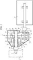
Figure 1 shows a schematic, substantially block diagram of a preferred embodiment of the aircraft power generating assembly in accordance with the teachings of the present invention, and located between an engine and a propulsion system of the aircraft; -
Figure 2 shows a schematic, substantially block diagram of a variation of a number of details inFigure 1 ; -
Figures 3 and4 are similar to and show variations of a detail inFigures 1 and2 respectively. - Number 1 in
Figure 1 indicates as a whole an assembly for generating electric or mechanical power on an aircraft (not shown). - Assembly 1 comprises a
rotary shaft 2 connected in angularly fixed manner to ashaft 3 of anengine 4 of the aircraft by a known angular connectingdevice 4a not descried in detail; and arotary shaft 5 connected in angularly fixed manner to aninput shaft 6 of a propulsion system 7 of the aircraft by a known angular connectingdevice 8 also not described in detail. - Assembly 1 comprises a supporting
frame 10, which, in the example shown, defines a closed outer casing, from which onlyshafts mechanical gear transmission 12; and anelectric power machine 13 associated withtransmission 12 and convertible to operate both as an electric power generator and a drive motor. - In the example shown,
mechanical transmission 12 comprises twoshafts frame 10 byrespective end bearings shafts -
Shafts respective bearings respective gears Figure 1 , and which, together withshafts device 4a, connectshaft 15 in angularly fixed manner toshaft 3. - As shown in
Figure 1 , machine 13 - which is conveniently, though not necessarily, of the type described in the Applicant's international patent applicationsPCT/IB2009/050219 andPCT/ IB2009/050214 - coaxially surrounds anintermediate portion 20 ofshaft 15 betweenbearings rotor 22 with independent sectors insertable/extractable by simply sliding radially with respect to the axis ofshaft 15, and lockable firmly with respect to one another. -
Rotor 22 is fitted in rotary manner toportion 20 ofshaft 15 with the interposition of twobearings 24, and is locked in angularly fixed manner toshaft 15 by areleasable coupling device 25. This comprises anangular locking member 26 fitted in angularly fixed manner toshaft 15, and which slides to and fromrotor 22 along the axis ofshaft 15, between a forward position (Figure 1 ) fittingrotor 22 toshaft 15, and a withdrawn release position, in whichrotor 22 andshaft 15 rotate freely with respect to each other to setmachine 13 to idle or safety mode. - As shown in
Figure 1 ,machine 13 comprises astator 28, also with independent sectors likerotor 22, and fitted firmly toframe 10, coaxially withshaft 15. - In the
Figure 3 variation,rotor 22 is fitted to aframe 22a of its own, which loosely surroundsportion 20 ofshaft 15 and is connected to fixedframe 10 with the interposition of twobearings rotor 22; andcoupling device 25 is interposed betweenshaft 15 andframe 22a. - In the
Figure 2 solution,shaft 14 is perpendicular toshafts shafts bevel gear pairs shaft 15 is connected in known manner to ashaft 31 of aspur gear train 32 housed completely inside supportingframe 10 and having anoutput shaft 33, which projects from supportingframe 10 to connectshaft 15 angularly to at least oneaccessory device 14, e.g. the fuel pump, outside supportingframe 10. In another variation,gear train 32 comprises a number ofoutput shafts 33 for respective accessory devices. - In the
Figure 4 variation,shaft 15 is shorter than in theFigure 2 solution, the twobearings bevel gear pair 30, andshaft 15 is still connected in angularly fixed manner toshaft 31, which is longer than in theFigure 2 solution and surrounded byelectric machine 13. As is theFigure 3 solution,rotor 22 is fitted to itsown frame 22a, which loosely surrounds an intermediate portion ofshaft 31 and is directly connected in rotary manner to fixedframe 10 with the interposition of twobearings rotor 22. In theFigure 4 solution,bearings frame 10; andcoupling device 25 is interposed betweenshaft 31 andframe 22a. - Compared with known solutions, the design of assembly 1 described - in particular, integrating
electric machine 13 inmechanical transmission 12 bypositioning rotor 22 about a shaft of the mechanical transmission, and connecting the rotor in angularly fixed manner to the shaft - above all greatly reduces the size of the mechanical transmission/electric machine assembly, thus gaining at least the space formerly occupied by the electric machine and the gear housing portion connected to it. - That is, compared with known solutions, in which the electric machine is located "behind"
mechanical transmission 12, the transmission described eliminates the gearing branch formerly provided specifically for the electric machine, thus saving at least one pair of gears and relative rolling bearings. - Unlike known solutions, when
electric machine 13 is operated as a current generator, i.e. is powered byengine 4, the transmission components downstream from the electric machine in the power direction need no longer be designed to take into account the power drawn by the electric machine, which normally accounts for large part of the total power drawn by the accessories mounted on the transmission casing. - Compared with solutions in which the electric machine is located "outside or behind" the transmission, mounting
electric machine 13 along a shaft of the transmission does not significantly impair maintenance and/or replacement of the electric machine, by employing couplings, such as axially-sliding flanged couplings, enabling lateral or axial removal of the electric machine, or by employing "independent sector" electric machines specially designed for easy assembly and removal. - Finally, the solution proposed can adopt the same safety measures commonly used in conventional solutions in the event of failure of the electric machine, e.g. a releasable device, which, when necessary, immediately isolates the electric machine to cut off electric power generation without having to turn off the propulsion or power generating system.
- Clearly, changes may be made to assembly 1 as described herein. In particular, the construction design of
electric machine 13 may differ from that described by way of example; power pickup fromshaft 3 may differ; and, in this connection, the mechanical transmission may obviously be connected to a secondary transmission shaft, as opposed to directly toshaft 3. -
Gear train 32 may also differ from the one described, and comprise, for example, a different number of shafts in the same or different positions from those shown by way of example.
Claims (14)
- An aircraft power generating assembly (1); the assembly comprising an electric machine (13), and a mechanical gear transmission (12) connected to said electric machine (13); the assembly (1) comprising:- a fixed supporting frame (10),- at least one rotary shaft (15;31) connected to the fixed supporting frame (10) to rotate about a fixed hinge axis, and- first and second angular connecting means (4a, 8) for connecting said rotary shaft (15;31) to respective further rotary input/output shafts (3,6; 3,33);said electric machine (13) comprising a rotor (22);
characterized in that said electric machine (13) is located between said first and second angular connecting means (4a, 8), and surrounds said rotary shaft (15;31)
said rotor (22) is connected angularly to said rotary shaft (15;31) by a releasable coupling device (25) comprising an angular locking member (26), which is fitted in angularly fixed manner to said rotary shaft (15;31) and is axially movable between- a forward position, in which the rotor (22) is locked in angularly fixed manner to the shaft (15;31), and- a withdrawn position, in which the rotor (22) and the shaft (15;31) rotate freely with respect to each other. - An assembly as claimed in Claim 1, characterized in that said rotor (22) is hollow and is fitted to said rotary shaft (15).
- An assembly as claimed in Claim 2, characterized in that said rotor (22) loosely surrounds said rotary shaft (15); and bearing means (24) are interposed directly between said rotor (22) and said rotary shaft (15).
- An assembly as claimed in Claim 2 or 3, characterized in that said releasable coupling device (25) is interposed directly between said rotor (22) and said rotary shaft (15;31).
- An assembly as claimed in Claim 1, characterized in that said rotor (22) is hollow, surrounds said rotary shaft (15;31) and is fitted to said fixed supporting frame (10) .
- An assembly as claimed in Claim 5, characterized in that said rotor (22) comprises its own supporting structure (22a); further bearing means (22b,22c) being interposed between said supporting structure (22a) and said fixed supporting frame (10).
- An assembly as claimed in Claim 6, characterized by also comprising an interface frame (A) interposed between said fixed supporting frame (10) and said further bearing means (22b,22c).
- An assembly as claimed in Claim 7, characterized in that said fixed supporting frame (10) is releasably connected to said interface frame (A).
- An assembly as claimed in Claim 7 or 8, characterized in that said releasable coupling device (25) is interposed directly between said rotary shaft (15;31) and said supporting structure (22a).
- An assembly as claimed in any one of the foregoing Claims, characterized in that said electric machine (13) comprises a stator (28) connected firmly to said fixed supporting frame (10).
- An assembly as claimed in Claim 10, characterized in that said fixed supporting frame (10) defines a closed outer casing; and said rotary shaft, said stator (28), and said rotor (22) are housed in said closed outer casing.
- An assembly as claimed in any one of the foregoing Claims, characterized in that said second angular connecting means (8) connects said rotary shaft (15) directly to a shaft (6) of a propulsion system (7) of the aircraft.
- An assembly as claimed in any one of Claims 1 to 11, characterized in that said second angular connecting means (8) connects said rotary shaft (15;31) to at least one accessory device (34) of the aircraft.
- An assembly as claimed in Claim 10, characterized in that said rotor (22) and said stator (28) comprise respective independent circumferential sectors connected releasably to one another.
Applications Claiming Priority (1)
| Application Number | Priority Date | Filing Date | Title |
|---|---|---|---|
| ITTO2011A000105A IT1404051B1 (en) | 2011-02-08 | 2011-02-08 | GROUP FOR POWER GENERATION ON BOARD OF A AIRCRAFT. |
Publications (2)
| Publication Number | Publication Date |
|---|---|
| EP2484882A1 EP2484882A1 (en) | 2012-08-08 |
| EP2484882B1 true EP2484882B1 (en) | 2019-07-31 |
Family
ID=43976437
Family Applications (1)
| Application Number | Title | Priority Date | Filing Date |
|---|---|---|---|
| EP12154585.9A Active EP2484882B1 (en) | 2011-02-08 | 2012-02-08 | Aircraft power generating assembly |
Country Status (5)
| Country | Link |
|---|---|
| US (1) | US9214841B2 (en) |
| EP (1) | EP2484882B1 (en) |
| CN (1) | CN102723808B (en) |
| CA (1) | CA2767449C (en) |
| IT (1) | IT1404051B1 (en) |
Families Citing this family (6)
| Publication number | Priority date | Publication date | Assignee | Title |
|---|---|---|---|---|
| US20150214816A1 (en) * | 2013-12-23 | 2015-07-30 | Oeco, Llc | Gear-driven generator with offset axis of rotation and integrated cooling system |
| FR3017660B1 (en) * | 2014-02-18 | 2018-05-04 | Safran Transmission Systems | AUXILIARY MACHINE DRIVE ASSEMBLY FOR DRIVING AUXILIARY MACHINES IN AN AIRCRAFT TURBOJET ENGINE |
| US10807729B2 (en) * | 2017-05-17 | 2020-10-20 | General Electric Company | Propulsion system for an aircraft |
| FR3073569B1 (en) * | 2017-11-15 | 2020-02-07 | Safran Helicopter Engines | TURBOPROPELLER COMPRISING A REDUCTION MECHANISM INCLUDING A CURRENT GENERATION DEVICE |
| IT202000002695A1 (en) * | 2020-02-11 | 2021-08-11 | Ge Avio Srl | GEAR TRANSMISSION UNIT FITTED WITH AN ELECTRIC MOTOR |
| FR3139864B1 (en) * | 2022-09-20 | 2024-10-18 | Safran Trans Systems | COMPACT ACCESSORY BOX WITH INTEGRATED ELECTRIC MACHINE |
Family Cites Families (11)
| Publication number | Priority date | Publication date | Assignee | Title |
|---|---|---|---|---|
| DE4321172C2 (en) * | 1993-06-25 | 1996-04-04 | Licentia Gmbh | Electric drive for a motor vehicle |
| DE4332323C2 (en) * | 1993-09-23 | 1995-11-30 | Leybold Ag | Geared motor with an electric motor having a hollow shaft |
| CN1078146C (en) * | 1996-05-24 | 2002-01-23 | 杨泰和 | Multifunctional composite power system |
| DE19850052A1 (en) * | 1998-10-30 | 2000-05-04 | Asea Brown Boveri | Generator with dual drive with two drive machines has first gearbox shaft arranged between generator shaft and slip ring shaft and second drive machine connected to second gearbox shaft |
| KR101093315B1 (en) * | 2003-06-09 | 2011-12-14 | 신꼬오덴끼가부시끼가이샤 | Power generation unit, and power supply unit used for this |
| DE102004026796A1 (en) * | 2004-06-02 | 2005-12-29 | Daimlerchrysler Ag | Exhaust gas turbocharger for an internal combustion engine and method for operating an exhaust gas turbocharger |
| GB0416344D0 (en) * | 2004-07-22 | 2004-08-25 | Rolls Royce Plc | Generator assembly |
| DE102007017332A1 (en) * | 2007-04-11 | 2008-10-16 | Flight - Design - GmbH Flugsportgeräte | aircraft |
| FR2933910B1 (en) * | 2008-07-18 | 2010-12-17 | Eurocopter France | HYBRID POWER PLANT AND METHOD FOR CONTROLLING SUCH A MOTOR INSTALLATION |
| ES2363897B1 (en) * | 2008-10-24 | 2012-07-04 | Airbus Operations, S.L. | AUXILIARY POWER UNIT (APU) OF AN AIRCRAFT |
| US8278774B2 (en) * | 2009-06-29 | 2012-10-02 | Pratt & Whitney Canada Corp. | Gas turbine with wired shaft forming part of a generator/motor assembly |
-
2011
- 2011-02-08 IT ITTO2011A000105A patent/IT1404051B1/en active
-
2012
- 2012-02-07 CA CA2767449A patent/CA2767449C/en not_active Expired - Fee Related
- 2012-02-08 EP EP12154585.9A patent/EP2484882B1/en active Active
- 2012-02-08 CN CN201210027628.1A patent/CN102723808B/en active Active
- 2012-02-08 US US13/368,655 patent/US9214841B2/en active Active
Non-Patent Citations (1)
| Title |
|---|
| None * |
Also Published As
| Publication number | Publication date |
|---|---|
| US20130038180A1 (en) | 2013-02-14 |
| CN102723808B (en) | 2017-04-12 |
| IT1404051B1 (en) | 2013-11-08 |
| US9214841B2 (en) | 2015-12-15 |
| CA2767449C (en) | 2019-07-16 |
| EP2484882A1 (en) | 2012-08-08 |
| ITTO20110105A1 (en) | 2012-08-09 |
| CN102723808A (en) | 2012-10-10 |
| CA2767449A1 (en) | 2012-08-08 |
Similar Documents
| Publication | Publication Date | Title |
|---|---|---|
| CA2767449C (en) | Aircraft power generating assembly | |
| JP5570690B2 (en) | Device for driving rotor of auxiliary equipment of turbine engine | |
| EP2530282B1 (en) | Dual drive of an accessory drive gearbox | |
| EP2519722B1 (en) | Turbofan engine with hp and lp power off-takes | |
| EP3936358B1 (en) | Dual-electric-motor driving system | |
| KR101052456B1 (en) | Wind power generator | |
| KR101540068B1 (en) | Driving device and corresponding mill | |
| CN104335460B (en) | Power generation unit of integrated gearbox design for aircraft engine | |
| EP2977315B1 (en) | Apparatus and methods for powering an electrical device associated with an aircraft rotor | |
| EP3957843B1 (en) | Hybrid through-flow gas turbine engine with electric motor and electric generator | |
| US8529391B2 (en) | Gear train for a wind turbine | |
| US9638302B2 (en) | Electric axle with a two gear transmission | |
| US12030662B2 (en) | Propulsion system for a helicopter | |
| CN106059171B (en) | Electric machine, motor vehicle transmissions and the method for producing electric machine | |
| US20140084677A1 (en) | Method for rationalising a chain of electrical components of an aircraft, implementation architecture and corresponding aircraft | |
| US20210404386A1 (en) | Gas turbine engine and aircraft with a gas turbine engine | |
| US8784247B2 (en) | Drive arrangement for a vehicle accessory | |
| US20060230853A1 (en) | Twin-clutch transmission | |
| CN103917778B (en) | The power train of fluid power generating unit | |
| CN116409126B (en) | Propulsion system for electric vehicle | |
| KR101349867B1 (en) | Powertrain unit for wind turbine, method of assembling the same and wind power generator having the same | |
| CN204109780U (en) | Integrated form hybrid power power drive system | |
| US20230265918A1 (en) | Rotary mechanical system and maintenance method of rotary mechanical system | |
| EP2594776B1 (en) | Integrated accessory gearbox and engine starter | |
| JPS6380735A (en) | Generating set |
Legal Events
| Date | Code | Title | Description |
|---|---|---|---|
| PUAI | Public reference made under article 153(3) epc to a published international application that has entered the european phase |
Free format text: ORIGINAL CODE: 0009012 |
|
| AK | Designated contracting states |
Kind code of ref document: A1 Designated state(s): AL AT BE BG CH CY CZ DE DK EE ES FI FR GB GR HR HU IE IS IT LI LT LU LV MC MK MT NL NO PL PT RO RS SE SI SK SM TR |
|
| AX | Request for extension of the european patent |
Extension state: BA ME |
|
| 17P | Request for examination filed |
Effective date: 20130208 |
|
| RAP1 | Party data changed (applicant data changed or rights of an application transferred) |
Owner name: GE AVIO S.R.L. |
|
| RAP1 | Party data changed (applicant data changed or rights of an application transferred) |
Owner name: GE AVIO S.R.L. |
|
| 17Q | First examination report despatched |
Effective date: 20160406 |
|
| STAA | Information on the status of an ep patent application or granted ep patent |
Free format text: STATUS: EXAMINATION IS IN PROGRESS |
|
| RIC1 | Information provided on ipc code assigned before grant |
Ipc: H02K 1/30 20060101ALI20180226BHEP Ipc: H02K 7/18 20060101ALI20180226BHEP Ipc: F01D 15/10 20060101AFI20180226BHEP Ipc: F02C 7/268 20060101ALI20180226BHEP Ipc: F02C 7/32 20060101ALI20180226BHEP Ipc: H02K 7/116 20060101ALI20180226BHEP Ipc: H02K 16/04 20060101ALN20180226BHEP |
|
| GRAP | Despatch of communication of intention to grant a patent |
Free format text: ORIGINAL CODE: EPIDOSNIGR1 |
|
| STAA | Information on the status of an ep patent application or granted ep patent |
Free format text: STATUS: GRANT OF PATENT IS INTENDED |
|
| RIC1 | Information provided on ipc code assigned before grant |
Ipc: F02C 7/268 20060101ALI20190117BHEP Ipc: F01D 15/10 20060101AFI20190117BHEP Ipc: F02C 7/32 20060101ALI20190117BHEP Ipc: H02K 16/04 20060101ALN20190117BHEP Ipc: H02K 7/18 20060101ALI20190117BHEP Ipc: H02K 7/116 20060101ALI20190117BHEP Ipc: H02K 1/30 20060101ALI20190117BHEP |
|
| INTG | Intention to grant announced |
Effective date: 20190207 |
|
| GRAJ | Information related to disapproval of communication of intention to grant by the applicant or resumption of examination proceedings by the epo deleted |
Free format text: ORIGINAL CODE: EPIDOSDIGR1 |
|
| STAA | Information on the status of an ep patent application or granted ep patent |
Free format text: STATUS: EXAMINATION IS IN PROGRESS |
|
| GRAR | Information related to intention to grant a patent recorded |
Free format text: ORIGINAL CODE: EPIDOSNIGR71 |
|
| GRAS | Grant fee paid |
Free format text: ORIGINAL CODE: EPIDOSNIGR3 |
|
| REG | Reference to a national code |
Ref country code: DE Ref legal event code: R079 Ref document number: 602012062388 Country of ref document: DE Free format text: PREVIOUS MAIN CLASS: F02C0007268000 Ipc: F01D0015100000 |
|
| STAA | Information on the status of an ep patent application or granted ep patent |
Free format text: STATUS: GRANT OF PATENT IS INTENDED |
|
| GRAA | (expected) grant |
Free format text: ORIGINAL CODE: 0009210 |
|
| STAA | Information on the status of an ep patent application or granted ep patent |
Free format text: STATUS: THE PATENT HAS BEEN GRANTED |
|
| INTC | Intention to grant announced (deleted) | ||
| INTG | Intention to grant announced |
Effective date: 20190618 |
|
| RIC1 | Information provided on ipc code assigned before grant |
Ipc: F02C 7/32 20060101ALI20190618BHEP Ipc: H02K 7/116 20060101ALI20190618BHEP Ipc: F01D 15/10 20060101AFI20190618BHEP Ipc: F02C 7/268 20060101ALI20190618BHEP Ipc: H02K 1/30 20060101ALI20190618BHEP Ipc: H02K 16/04 20060101ALN20190618BHEP Ipc: H02K 7/18 20060101ALI20190618BHEP |
|
| AK | Designated contracting states |
Kind code of ref document: B1 Designated state(s): AL AT BE BG CH CY CZ DE DK EE ES FI FR GB GR HR HU IE IS IT LI LT LU LV MC MK MT NL NO PL PT RO RS SE SI SK SM TR |
|
| REG | Reference to a national code |
Ref country code: CH Ref legal event code: EP Ref country code: GB Ref legal event code: FG4D |
|
| REG | Reference to a national code |
Ref country code: AT Ref legal event code: REF Ref document number: 1161113 Country of ref document: AT Kind code of ref document: T Effective date: 20190815 |
|
| REG | Reference to a national code |
Ref country code: IE Ref legal event code: FG4D |
|
| REG | Reference to a national code |
Ref country code: DE Ref legal event code: R096 Ref document number: 602012062388 Country of ref document: DE |
|
| REG | Reference to a national code |
Ref country code: NL Ref legal event code: MP Effective date: 20190731 |
|
| REG | Reference to a national code |
Ref country code: LT Ref legal event code: MG4D |
|
| REG | Reference to a national code |
Ref country code: AT Ref legal event code: MK05 Ref document number: 1161113 Country of ref document: AT Kind code of ref document: T Effective date: 20190731 |
|
| PG25 | Lapsed in a contracting state [announced via postgrant information from national office to epo] |
Ref country code: LT Free format text: LAPSE BECAUSE OF FAILURE TO SUBMIT A TRANSLATION OF THE DESCRIPTION OR TO PAY THE FEE WITHIN THE PRESCRIBED TIME-LIMIT Effective date: 20190731 Ref country code: PT Free format text: LAPSE BECAUSE OF FAILURE TO SUBMIT A TRANSLATION OF THE DESCRIPTION OR TO PAY THE FEE WITHIN THE PRESCRIBED TIME-LIMIT Effective date: 20191202 Ref country code: SE Free format text: LAPSE BECAUSE OF FAILURE TO SUBMIT A TRANSLATION OF THE DESCRIPTION OR TO PAY THE FEE WITHIN THE PRESCRIBED TIME-LIMIT Effective date: 20190731 Ref country code: BG Free format text: LAPSE BECAUSE OF FAILURE TO SUBMIT A TRANSLATION OF THE DESCRIPTION OR TO PAY THE FEE WITHIN THE PRESCRIBED TIME-LIMIT Effective date: 20191031 Ref country code: AT Free format text: LAPSE BECAUSE OF FAILURE TO SUBMIT A TRANSLATION OF THE DESCRIPTION OR TO PAY THE FEE WITHIN THE PRESCRIBED TIME-LIMIT Effective date: 20190731 Ref country code: NL Free format text: LAPSE BECAUSE OF FAILURE TO SUBMIT A TRANSLATION OF THE DESCRIPTION OR TO PAY THE FEE WITHIN THE PRESCRIBED TIME-LIMIT Effective date: 20190731 Ref country code: HR Free format text: LAPSE BECAUSE OF FAILURE TO SUBMIT A TRANSLATION OF THE DESCRIPTION OR TO PAY THE FEE WITHIN THE PRESCRIBED TIME-LIMIT Effective date: 20190731 Ref country code: NO Free format text: LAPSE BECAUSE OF FAILURE TO SUBMIT A TRANSLATION OF THE DESCRIPTION OR TO PAY THE FEE WITHIN THE PRESCRIBED TIME-LIMIT Effective date: 20191031 Ref country code: FI Free format text: LAPSE BECAUSE OF FAILURE TO SUBMIT A TRANSLATION OF THE DESCRIPTION OR TO PAY THE FEE WITHIN THE PRESCRIBED TIME-LIMIT Effective date: 20190731 |
|
| PG25 | Lapsed in a contracting state [announced via postgrant information from national office to epo] |
Ref country code: IS Free format text: LAPSE BECAUSE OF FAILURE TO SUBMIT A TRANSLATION OF THE DESCRIPTION OR TO PAY THE FEE WITHIN THE PRESCRIBED TIME-LIMIT Effective date: 20191130 Ref country code: RS Free format text: LAPSE BECAUSE OF FAILURE TO SUBMIT A TRANSLATION OF THE DESCRIPTION OR TO PAY THE FEE WITHIN THE PRESCRIBED TIME-LIMIT Effective date: 20190731 Ref country code: LV Free format text: LAPSE BECAUSE OF FAILURE TO SUBMIT A TRANSLATION OF THE DESCRIPTION OR TO PAY THE FEE WITHIN THE PRESCRIBED TIME-LIMIT Effective date: 20190731 Ref country code: ES Free format text: LAPSE BECAUSE OF FAILURE TO SUBMIT A TRANSLATION OF THE DESCRIPTION OR TO PAY THE FEE WITHIN THE PRESCRIBED TIME-LIMIT Effective date: 20190731 Ref country code: AL Free format text: LAPSE BECAUSE OF FAILURE TO SUBMIT A TRANSLATION OF THE DESCRIPTION OR TO PAY THE FEE WITHIN THE PRESCRIBED TIME-LIMIT Effective date: 20190731 Ref country code: GR Free format text: LAPSE BECAUSE OF FAILURE TO SUBMIT A TRANSLATION OF THE DESCRIPTION OR TO PAY THE FEE WITHIN THE PRESCRIBED TIME-LIMIT Effective date: 20191101 |
|
| PG25 | Lapsed in a contracting state [announced via postgrant information from national office to epo] |
Ref country code: TR Free format text: LAPSE BECAUSE OF FAILURE TO SUBMIT A TRANSLATION OF THE DESCRIPTION OR TO PAY THE FEE WITHIN THE PRESCRIBED TIME-LIMIT Effective date: 20190731 |
|
| PG25 | Lapsed in a contracting state [announced via postgrant information from national office to epo] |
Ref country code: RO Free format text: LAPSE BECAUSE OF FAILURE TO SUBMIT A TRANSLATION OF THE DESCRIPTION OR TO PAY THE FEE WITHIN THE PRESCRIBED TIME-LIMIT Effective date: 20190731 Ref country code: EE Free format text: LAPSE BECAUSE OF FAILURE TO SUBMIT A TRANSLATION OF THE DESCRIPTION OR TO PAY THE FEE WITHIN THE PRESCRIBED TIME-LIMIT Effective date: 20190731 Ref country code: IT Free format text: LAPSE BECAUSE OF FAILURE TO SUBMIT A TRANSLATION OF THE DESCRIPTION OR TO PAY THE FEE WITHIN THE PRESCRIBED TIME-LIMIT Effective date: 20190731 Ref country code: DK Free format text: LAPSE BECAUSE OF FAILURE TO SUBMIT A TRANSLATION OF THE DESCRIPTION OR TO PAY THE FEE WITHIN THE PRESCRIBED TIME-LIMIT Effective date: 20190731 Ref country code: PL Free format text: LAPSE BECAUSE OF FAILURE TO SUBMIT A TRANSLATION OF THE DESCRIPTION OR TO PAY THE FEE WITHIN THE PRESCRIBED TIME-LIMIT Effective date: 20190731 |
|
| PG25 | Lapsed in a contracting state [announced via postgrant information from national office to epo] |
Ref country code: SK Free format text: LAPSE BECAUSE OF FAILURE TO SUBMIT A TRANSLATION OF THE DESCRIPTION OR TO PAY THE FEE WITHIN THE PRESCRIBED TIME-LIMIT Effective date: 20190731 Ref country code: CZ Free format text: LAPSE BECAUSE OF FAILURE TO SUBMIT A TRANSLATION OF THE DESCRIPTION OR TO PAY THE FEE WITHIN THE PRESCRIBED TIME-LIMIT Effective date: 20190731 Ref country code: IS Free format text: LAPSE BECAUSE OF FAILURE TO SUBMIT A TRANSLATION OF THE DESCRIPTION OR TO PAY THE FEE WITHIN THE PRESCRIBED TIME-LIMIT Effective date: 20200224 Ref country code: SM Free format text: LAPSE BECAUSE OF FAILURE TO SUBMIT A TRANSLATION OF THE DESCRIPTION OR TO PAY THE FEE WITHIN THE PRESCRIBED TIME-LIMIT Effective date: 20190731 |
|
| REG | Reference to a national code |
Ref country code: DE Ref legal event code: R097 Ref document number: 602012062388 Country of ref document: DE |
|
| PLBE | No opposition filed within time limit |
Free format text: ORIGINAL CODE: 0009261 |
|
| STAA | Information on the status of an ep patent application or granted ep patent |
Free format text: STATUS: NO OPPOSITION FILED WITHIN TIME LIMIT |
|
| PG2D | Information on lapse in contracting state deleted |
Ref country code: IS |
|
| PG25 | Lapsed in a contracting state [announced via postgrant information from national office to epo] |
Ref country code: IS Free format text: LAPSE BECAUSE OF FAILURE TO SUBMIT A TRANSLATION OF THE DESCRIPTION OR TO PAY THE FEE WITHIN THE PRESCRIBED TIME-LIMIT Effective date: 20191030 |
|
| 26N | No opposition filed |
Effective date: 20200603 |
|
| PG25 | Lapsed in a contracting state [announced via postgrant information from national office to epo] |
Ref country code: SI Free format text: LAPSE BECAUSE OF FAILURE TO SUBMIT A TRANSLATION OF THE DESCRIPTION OR TO PAY THE FEE WITHIN THE PRESCRIBED TIME-LIMIT Effective date: 20190731 |
|
| REG | Reference to a national code |
Ref country code: CH Ref legal event code: PL |
|
| REG | Reference to a national code |
Ref country code: BE Ref legal event code: MM Effective date: 20200229 |
|
| PG25 | Lapsed in a contracting state [announced via postgrant information from national office to epo] |
Ref country code: LU Free format text: LAPSE BECAUSE OF NON-PAYMENT OF DUE FEES Effective date: 20200208 Ref country code: MC Free format text: LAPSE BECAUSE OF FAILURE TO SUBMIT A TRANSLATION OF THE DESCRIPTION OR TO PAY THE FEE WITHIN THE PRESCRIBED TIME-LIMIT Effective date: 20190731 |
|
| PG25 | Lapsed in a contracting state [announced via postgrant information from national office to epo] |
Ref country code: LI Free format text: LAPSE BECAUSE OF NON-PAYMENT OF DUE FEES Effective date: 20200229 Ref country code: CH Free format text: LAPSE BECAUSE OF NON-PAYMENT OF DUE FEES Effective date: 20200229 |
|
| PG25 | Lapsed in a contracting state [announced via postgrant information from national office to epo] |
Ref country code: IE Free format text: LAPSE BECAUSE OF NON-PAYMENT OF DUE FEES Effective date: 20200208 |
|
| PG25 | Lapsed in a contracting state [announced via postgrant information from national office to epo] |
Ref country code: BE Free format text: LAPSE BECAUSE OF NON-PAYMENT OF DUE FEES Effective date: 20200229 |
|
| PG25 | Lapsed in a contracting state [announced via postgrant information from national office to epo] |
Ref country code: MT Free format text: LAPSE BECAUSE OF FAILURE TO SUBMIT A TRANSLATION OF THE DESCRIPTION OR TO PAY THE FEE WITHIN THE PRESCRIBED TIME-LIMIT Effective date: 20190731 Ref country code: CY Free format text: LAPSE BECAUSE OF FAILURE TO SUBMIT A TRANSLATION OF THE DESCRIPTION OR TO PAY THE FEE WITHIN THE PRESCRIBED TIME-LIMIT Effective date: 20190731 |
|
| PG25 | Lapsed in a contracting state [announced via postgrant information from national office to epo] |
Ref country code: MK Free format text: LAPSE BECAUSE OF FAILURE TO SUBMIT A TRANSLATION OF THE DESCRIPTION OR TO PAY THE FEE WITHIN THE PRESCRIBED TIME-LIMIT Effective date: 20190731 |
|
| P01 | Opt-out of the competence of the unified patent court (upc) registered |
Effective date: 20230418 |
|
| PGFP | Annual fee paid to national office [announced via postgrant information from national office to epo] |
Ref country code: GB Payment date: 20260122 Year of fee payment: 15 |
|
| PGFP | Annual fee paid to national office [announced via postgrant information from national office to epo] |
Ref country code: DE Payment date: 20260121 Year of fee payment: 15 |
|
| PGFP | Annual fee paid to national office [announced via postgrant information from national office to epo] |
Ref country code: FR Payment date: 20260121 Year of fee payment: 15 |