EP2484872A1 - Passive cooling system for a turbomachine - Google Patents
Passive cooling system for a turbomachine Download PDFInfo
- Publication number
- EP2484872A1 EP2484872A1 EP12154127A EP12154127A EP2484872A1 EP 2484872 A1 EP2484872 A1 EP 2484872A1 EP 12154127 A EP12154127 A EP 12154127A EP 12154127 A EP12154127 A EP 12154127A EP 2484872 A1 EP2484872 A1 EP 2484872A1
- Authority
- EP
- European Patent Office
- Prior art keywords
- fluid
- fluid passage
- turbomachine
- housing
- stationary member
- Prior art date
- Legal status (The legal status is an assumption and is not a legal conclusion. Google has not performed a legal analysis and makes no representation as to the accuracy of the status listed.)
- Granted
Links
- 238000001816 cooling Methods 0.000 title claims description 20
- 239000012530 fluid Substances 0.000 claims abstract description 108
- 238000000034 method Methods 0.000 claims description 6
- 238000007599 discharging Methods 0.000 claims 1
- 239000007789 gas Substances 0.000 description 15
- 239000012809 cooling fluid Substances 0.000 description 8
- 230000004075 alteration Effects 0.000 description 1
- 239000000446 fuel Substances 0.000 description 1
- 238000006467 substitution reaction Methods 0.000 description 1
Images



Classifications
-
- F—MECHANICAL ENGINEERING; LIGHTING; HEATING; WEAPONS; BLASTING
- F01—MACHINES OR ENGINES IN GENERAL; ENGINE PLANTS IN GENERAL; STEAM ENGINES
- F01D—NON-POSITIVE DISPLACEMENT MACHINES OR ENGINES, e.g. STEAM TURBINES
- F01D11/00—Preventing or minimising internal leakage of working-fluid, e.g. between stages
- F01D11/08—Preventing or minimising internal leakage of working-fluid, e.g. between stages for sealing space between rotor blade tips and stator
- F01D11/10—Preventing or minimising internal leakage of working-fluid, e.g. between stages for sealing space between rotor blade tips and stator using sealing fluid, e.g. steam
-
- F—MECHANICAL ENGINEERING; LIGHTING; HEATING; WEAPONS; BLASTING
- F01—MACHINES OR ENGINES IN GENERAL; ENGINE PLANTS IN GENERAL; STEAM ENGINES
- F01D—NON-POSITIVE DISPLACEMENT MACHINES OR ENGINES, e.g. STEAM TURBINES
- F01D25/00—Component parts, details, or accessories, not provided for in, or of interest apart from, other groups
- F01D25/08—Cooling; Heating; Heat-insulation
- F01D25/12—Cooling
Definitions
- the subject matter disclosed herein relates to the art of turbomachines and, more particularly, to a passive cooling system for a turbomachine.
- Turbomachines typically include a compressor operationally linked to a turbine.
- Turbomachines also include a combustor that receives fuel and air which is mixed and ignited to form a high energy fluid or hot gases. The hot gases are then directed into a hot gas path toward turbine buckets or blades. Energy from the hot gases imparts a rotational force to the turbine blades.
- a portion of the hot gases escapes from the hot gas path and flows over a cover portion of the blades.
- the hot gases typically impinge upon a front, top side of the cover portion. Continuous exposure to the hot gases leads to a significant reduction in blade tip creep life. As such, cooling tip portions of the blades will lead to a longer service life for the turbomachine.
- the invention resides in a turbomachine including a housing having an outer surface and an inner surface that defines an interior portion.
- the housing includes a fluid plenum.
- a rotating member is arranged within the housing.
- the rotating member includes at least one bucket having a base portion and a tip portion.
- a stationary member is mounted to the inner surface of the housing adjacent the tip portion of the at least one bucket.
- At least one fluid passage passes through at least a portion of the stationary member.
- the at least one fluid passage includes a fluid inlet fluidly coupled to the fluid plenum and a fluid outlet exposed to the interior portion.
- the fluid outlet is configured and disposed to direct a flow of fluid toward the tip portion of the at least one bucket.
- the invention resides in a method of passively cooling a turbomachine including rotating a rotating member that includes at least one bucket having a tip portion.
- the tip portion passes in proximity to a stationary member.
- a fluid flow is passed through a fluid plenum, formed in a housing of the turbomachine, toward the stationary member.
- the fluid flow is guided through at least one fluid passage, that extends from the fluid plenum through at least a portion of the stationary member, toward the tip portion of the at least one bucket for passively cooling the turbomachine.
- Turbomachine system 2 includes a first turbomachine that takes the form of a compressor portion 4 and a second turbomachine that takes the form of a turbine portion 6.
- Compressor portion 4 includes a compressor housing 8 and turbine portion 6 includes a turbine housing 10.
- Turbine housing 10 includes an outer surface 12 and an inner surface 14 that defines an interior portion 15.
- Compressor portion 4 is linked to turbine portion 6 through a common compressor/turbine shaft or rotor 16.
- Compressor portion 4 is also linked to turbine portion 6 through a plurality of circumferentially spaced combustors, one of which is indicated at 17.
- turbine portion 6 includes first, second and third stage rotating members or wheels 20-22 having an associated plurality of blade members or buckets 28-30. Wheels 20-22 and buckets 28-30 in conjunction with corresponding stator vanes 33-35 define various stages of turbine portion 6. In operation, buckets 28-30 rotate in close proximity to inner surface 14 of turbine housing 10.
- a plurality of stationary or shroud members is mounted to inner surface 14 through first and second hook sections 41 and 42.
- shroud member 40 defines a flow path (not separately labeled) for high pressure gases flowing over buckets 28-30.
- each bucket 28-30 is similarly formed such that a detailed description will follow with reference to bucket 28 with an understanding that the remaining buckets 29 and 30 include corresponding structure.
- bucket 28 includes a first or base portion 44 that extends to a second or tip portion 45 through an airfoil portion 46.
- Tip portion 45 is shown, in the exemplary embodiment, to include a projection 47.
- Hot gases flowing through the flow path from combustor 17 pass between tip portion 45 of bucket 28 along inner surface 14 and shroud member 40. As such, tip portion 45 is exposed to elevated temperatures associated with the hot gases.
- turbine portion 6 includes a passive cooling system 50.
- turbine housing 10 includes a housing member 60 that defines, in part, a fluid plenum 62.
- Housing member 60 includes a flange 64 having a first flange member 67, a second flange member 69, and a third flange member 70 that collectively defme a channel 73.
- flange 64 includes a first plurality of fluid passage sections 77-82 that extend through second flange member 69.
- Flange 64 also includes a plurality of channels 84-89 formed in third flange member 70. Channels 84-89 defme a plurality of first fluid passage portions 91-96.
- the first plurality of fluid passage sections 77-82 and channels 84-89 are fluidly connected to fluid plenum 62.
- Fluid passage section 77 includes a first end or inlet 103 that extends to a second end or outlet 104. Inlet 103 is open to fluid plenum 62 and outlet 104 is open to interior portion 15.
- Fluid passage portion 91 includes a first end or inlet section 107 that extends through flange 64 to a second end or outlet section 108. Inlet section 107 is open to fluid plenum 62 and outlet section 108 is open to interior portion 15.
- shroud 40 includes a second plurality of fluid passage sections 128-133 that extend through hook section 41.
- Each of the second plurality of fluid passage sections 128-133 includes a fluid inlet 135 and a fluid outlet 136 such as shown on fluid passage section 128.
- Each fluid outlet 136 is formed on an angled surface 139 of shroud 40.
- each of the second plurality of fluid passage sections 128-133 registers with corresponding ones of the first plurality of fluid passage sections 77-81 to form a first plurality of fluid passages 142-147.
- Shroud 40 is also shown to include a plurality of channels 152-157 formed in an outer surface 160 of hook section 41.
- Channels 152-157 define a second plurality of fluid passage portions 161-166.
- the first and second pluralities of fluid passages 142-147, and 171-176 form passive cooling system 50. That is, the first and second pluralities of fluid passages 142-147; and 171-176 deliver cooling fluid from fluid plenum 62 to interior portion 15.
- the cooling fluid is directed through shroud member 40 toward tip portion 45 of bucket 28 as well as other associated buckets that form the turbine stage.
- the cooling fluid enters into and mixes with the hot gases that are flowing along the flow path at tip portion 45.
- the introduction of the cooling fluid tempers, e.g., reduces a temperature of, the hot gases at tip portion 45. In this manner, cooling system 50 enhances an over all service life of bucket(s) 28 by reducing a potential for creep and other mechanical failures.
- cooling system 50 can be configured to guide the cooling fluid into a vortex chamber 200 formed in a shroud 240 as shown in FIG. 7 wherein like reference numbers represent corresponding parts in the respective views.
- the introduction of cooling fluid into vortex chamber 200 creates a turbulence that enhances mixing to further lower temperatures of the hot gases at tip portion 45.
- the exemplary embodiments provide a system for passively cooling tip portions of rotating components in a turbomachine.
- the cooling system is shown to include both a first and second plurality of fluid passages, exemplary embodiments could be constructed that include one or the other of the first and second plurality of fluid passages.
- the exemplary embodiments could be employed in a variety of turbomachine systems.
- the cooling fluid could be delivered through other stationary components of the turbomachine.
Landscapes
- Engineering & Computer Science (AREA)
- Mechanical Engineering (AREA)
- General Engineering & Computer Science (AREA)
- Turbine Rotor Nozzle Sealing (AREA)
Abstract
Description
- The subject matter disclosed herein relates to the art of turbomachines and, more particularly, to a passive cooling system for a turbomachine.
- Turbomachines typically include a compressor operationally linked to a turbine. Turbomachines also include a combustor that receives fuel and air which is mixed and ignited to form a high energy fluid or hot gases. The hot gases are then directed into a hot gas path toward turbine buckets or blades. Energy from the hot gases imparts a rotational force to the turbine blades. During operation, a portion of the hot gases escapes from the hot gas path and flows over a cover portion of the blades. The hot gases typically impinge upon a front, top side of the cover portion. Continuous exposure to the hot gases leads to a significant reduction in blade tip creep life. As such, cooling tip portions of the blades will lead to a longer service life for the turbomachine. Currently there exist various cooling systems for lowering turbine blade temperatures. Conventional cooling systems pass a cooling flow internally though rotating airfoil portions of the blades. The cooling airflow either travels through the rotating airfoil portions and passes out from tip portions of the blades, or circulates back through the airfoil portions.
- According to one aspect, the invention resides in a turbomachine including a housing having an outer surface and an inner surface that defines an interior portion. The housing includes a fluid plenum. A rotating member is arranged within the housing. The rotating member includes at least one bucket having a base portion and a tip portion. A stationary member is mounted to the inner surface of the housing adjacent the tip portion of the at least one bucket. At least one fluid passage passes through at least a portion of the stationary member. The at least one fluid passage includes a fluid inlet fluidly coupled to the fluid plenum and a fluid outlet exposed to the interior portion. The fluid outlet is configured and disposed to direct a flow of fluid toward the tip portion of the at least one bucket.
- According to another aspect, the invention resides in a method of passively cooling a turbomachine including rotating a rotating member that includes at least one bucket having a tip portion. The tip portion passes in proximity to a stationary member. A fluid flow is passed through a fluid plenum, formed in a housing of the turbomachine, toward the stationary member. The fluid flow is guided through at least one fluid passage, that extends from the fluid plenum through at least a portion of the stationary member, toward the tip portion of the at least one bucket for passively cooling the turbomachine.
- These and other advantages and features will become more apparent from the following description taken in conjunction with the drawings.
- Embodiments of the present invention will now be described, by way of example only, with reference to the accompanying drawings in which:
-
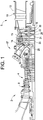
FIG. 1 is a cross-sectional view of a turbomachine including a passive cooling system in accordance with an exemplary embodiment; -
FIG 2 is a detail view of a plurality of turbine stages of a turbine portion of the turbomachine ofFIG. 1 ; -
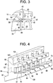
FIG. 3 is detail view of one of the plurality of turbine stages ofFIG. 2 illustrating a shroud member connected to a housing member; -
FIG. 4 is a lower partial perspective view of housing member ofFIG. 3 ; -
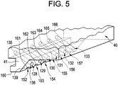
FIG. 5 is a lower partial perspective view of the shroud member ofFIG. 3 ; -
FIG. 6 is a lower partial perspective view of the shroud member connected to the housing member to form the passive cooling system of the exemplary embodiment; and -
FIG. 7 is a schematic view of a turbine stage in accordance with another aspect of the exemplary embodiment illustrating a passive cooling flow. - The detailed description explains embodiments of the invention, together with advantages and features, by way of example with reference to the drawings.
- With reference to
FIGs. 1 and2 , a turbomachine system constructed in accordance with an exemplary embodiment is indicated generally at 2.Turbomachine system 2 includes a first turbomachine that takes the form of acompressor portion 4 and a second turbomachine that takes the form of aturbine portion 6.Compressor portion 4 includes acompressor housing 8 andturbine portion 6 includes aturbine housing 10.Turbine housing 10 includes anouter surface 12 and aninner surface 14 that defines aninterior portion 15.Compressor portion 4 is linked toturbine portion 6 through a common compressor/turbine shaft orrotor 16.Compressor portion 4 is also linked toturbine portion 6 through a plurality of circumferentially spaced combustors, one of which is indicated at 17. In the exemplary embodiment shown,turbine portion 6 includes first, second and third stage rotating members or wheels 20-22 having an associated plurality of blade members or buckets 28-30. Wheels 20-22 and buckets 28-30 in conjunction with corresponding stator vanes 33-35 define various stages ofturbine portion 6. In operation, buckets 28-30 rotate in close proximity toinner surface 14 ofturbine housing 10. - In the exemplary embodiment shown, a plurality of stationary or shroud members, one of which is indicated at 40, is mounted to
inner surface 14 through first andsecond hook sections shroud member 40 defines a flow path (not separately labeled) for high pressure gases flowing over buckets 28-30. At this point, it should be understood that each bucket 28-30 is similarly formed such that a detailed description will follow with reference tobucket 28 with an understanding that theremaining buckets bucket 28 includes a first orbase portion 44 that extends to a second ortip portion 45 through anairfoil portion 46.Tip portion 45 is shown, in the exemplary embodiment, to include aprojection 47. Hot gases flowing through the flow path fromcombustor 17 pass betweentip portion 45 ofbucket 28 alonginner surface 14 andshroud member 40. As such,tip portion 45 is exposed to elevated temperatures associated with the hot gases. In order to lower localized temperatures attip portion 45,turbine portion 6 includes apassive cooling system 50. - As best shown in
FIGs. 3-5 ,turbine housing 10 includes ahousing member 60 that defines, in part, afluid plenum 62.Housing member 60 includes aflange 64 having afirst flange member 67, asecond flange member 69, and athird flange member 70 that collectively defme achannel 73. In accordance with an exemplary embodiment,flange 64 includes a first plurality of fluid passage sections 77-82 that extend throughsecond flange member 69.Flange 64 also includes a plurality of channels 84-89 formed inthird flange member 70. Channels 84-89 defme a plurality of first fluid passage portions 91-96. As will become evident below, the first plurality of fluid passage sections 77-82 and channels 84-89 are fluidly connected tofluid plenum 62. - As each of the first plurality of fluid passage sections 77-82 are similarly formed, a detailed description will follow referencing
fluid passage section 77 with an understanding that the remaining fluid passage sections 78-82 include corresponding structure.Fluid passage section 77 includes a first end orinlet 103 that extends to a second end oroutlet 104.Inlet 103 is open tofluid plenum 62 andoutlet 104 is open tointerior portion 15. Similarly, as each of the plurality of first fluid passage portions 91-96 are similarly formed, a detailed description will follow referencing firstfluid passage portion 91 with an understanding that the remaining fluid passage portions 92-96 include corresponding structure.Fluid passage portion 91 includes a first end orinlet section 107 that extends throughflange 64 to a second end oroutlet section 108.Inlet section 107 is open tofluid plenum 62 andoutlet section 108 is open tointerior portion 15. - In further accordance with the exemplary embodiment,
shroud 40 includes a second plurality of fluid passage sections 128-133 that extend throughhook section 41. Each of the second plurality of fluid passage sections 128-133 includes afluid inlet 135 and afluid outlet 136 such as shown onfluid passage section 128. Eachfluid outlet 136 is formed on anangled surface 139 ofshroud 40. As best shown inFIG. 6 , each of the second plurality of fluid passage sections 128-133 registers with corresponding ones of the first plurality of fluid passage sections 77-81 to form a first plurality of fluid passages 142-147.Shroud 40 is also shown to include a plurality of channels 152-157 formed in anouter surface 160 ofhook section 41. Channels 152-157 define a second plurality of fluid passage portions 161-166. Onceshroud 40 is installed toturbine housing 10, the second plurality of fluid passage portions 161-166 register with the first plurality of fluid passage portions 91-96 to establish a second plurality of fluid passages 171-176. - The first and second pluralities of fluid passages 142-147, and 171-176 form
passive cooling system 50. That is, the first and second pluralities of fluid passages 142-147; and 171-176 deliver cooling fluid fromfluid plenum 62 tointerior portion 15. The cooling fluid is directed throughshroud member 40 towardtip portion 45 ofbucket 28 as well as other associated buckets that form the turbine stage. The cooling fluid enters into and mixes with the hot gases that are flowing along the flow path attip portion 45. The introduction of the cooling fluid tempers, e.g., reduces a temperature of, the hot gases attip portion 45. In this manner, coolingsystem 50 enhances an over all service life of bucket(s) 28 by reducing a potential for creep and other mechanical failures. In addition to injecting cooling fluid directly intointerior portion 15 attip portion 45,cooling system 50 can be configured to guide the cooling fluid into avortex chamber 200 formed in ashroud 240 as shown inFIG. 7 wherein like reference numbers represent corresponding parts in the respective views. The introduction of cooling fluid intovortex chamber 200 creates a turbulence that enhances mixing to further lower temperatures of the hot gases attip portion 45. - At this point it should be understood that the exemplary embodiments provide a system for passively cooling tip portions of rotating components in a turbomachine. Also, it should be understood that while the cooling system is shown to include both a first and second plurality of fluid passages, exemplary embodiments could be constructed that include one or the other of the first and second plurality of fluid passages. Further, while shown in connection with a gas turbomachine, it should be understood that the exemplary embodiments could be employed in a variety of turbomachine systems. Additionally, while shown passing through a turbine shroud, it should be understood that the cooling fluid could be delivered through other stationary components of the turbomachine.
- While the invention has been described in detail in connection with only a limited number of embodiments, it should be readily understood that the invention is not limited to such disclosed embodiments. Rather, the invention can be modified to incorporate any number of variations, alterations, substitutions or equivalent arrangements not heretofore described, but which are commensurate with the spirit and scope of the invention. Additionally, while various embodiments of the invention have been described, it is to be understood that aspects of the invention may include only some of the described embodiments. Accordingly, the invention is not to be seen as limited by the foregoing description, but is only limited by the scope of the appended claims.
Claims (15)
- A turbomachine (2) comprising:a housing (60) having an outer surface (12) and an inner surface (14) that defines an interior portion (15), the housing (60) including a fluid plenum (62);a rotating member (20, 21, 22)arranged within the housing (60), the rotating member (20, 21, 22)including at least one bucket (28, 29, 30) having a base portion and a tip portion (45);a stationary member mounted to the inner surface (14) of the housing (60) adjacent the tip portion (45) of the at least one bucket (28, 29, 30); andat least one fluid passage passing through at least a portion of the stationary member, the at least one fluid passage including a fluid inlet fluidly coupled to the fluid plenum (62) and a fluid outlet exposed to the interior portion (15), the fluid outlet being configured and disposed to direct a flow of fluid toward the tip portion (45) of the at least one bucket (28, 29, 30).
- The turbomachine (2) according to claim 1, wherein the at least one fluid passage includes a fluid passage section that extends entirely through the stationary member.
- The turbomachine (2) according to claim 1, wherein the at least one fluid passage is defined between the stationary member and the housing (60).
- The turbomachine (2) according to claim 3, wherein the at least one fluid passage includes a first fluid passage portion formed in the stationary member and a second passage portion formed in the housing (60).
- The turbomachine (2) according to claim 1, wherein the at least one fluid passage includes a first fluid passage having a fluid passage section that passes entirely through the stationary member and a second fluid passage, the second fluid passage having a first fluid passage portion formed in the stationary member and second passage portion formed in the housing (60).
- The turbomachine (2) according to claim 1, wherein the stationary member includes a vortex chamber (200), the fluid outlet of the at least one fluid passage opening into the vortex chamber (200).
- The turbomachine (2) according to claim 1, wherein the stationary member comprises a shroud member having at least one hook section (41), the at least one fluid passage passing through at least a portion of the hook section (41).
- The turbomachine (2) according to claim 7, wherein the at least one fluid passage includes a fluid passage section that passes entirely through the at least one hook section (41) of the shroud member (40, 240).
- The turbomachine (2) according to claim 7, wherein the at least one fluid passage includes a first fluid passage portion formed in the at least one hook section and a second passage portion formed in the housing (60).
- The turbomachine (2) according to claim 7, wherein the at least one fluid passage includes a first fluid passage including a fluid passage section that passes entirely through the at least one hook section (41) and a second fluid passage, the second fluid passage having a first fluid passage portion formed in the at least one hook section (41) and second passage portion formed in the housing (60).
- A method of passively cooling a turbomachine (2) comprises:rotating a rotating member (20,21,22) including at least one bucket (26,29,30) having a tip portion (45), the tip portion passing in proximity to a stationary member;passing a fluid flow through a fluid plenum (62) formed in a housing (60) of the turbomachine (2) toward the stationary member; andguiding the fluid flow through at least one fluid passage that extends from the fluid plenum (62) through at least a portion of the stationary member toward the tip portion (45) of the at least one bucket (28,29,30) for passively cooling the turbomachine (2).
- The method of claim 11, wherein guiding the fluid flow through the at least one fluid passage includes passing the fluid flow through a plurality of fluid passage sections that extend entirely through the stationary member.
- The method of claim 11 wherein guiding the fluid flow through the at least one fluid passage includes passing the fluid flow through a plurality of fluid passages that are defined between the stationary member and the housing (60).
- The method of claim 11, wherein guiding the fluid flow through the at least one fluid passage includes passing the fluid flow through a first fluid passage having a fluid passage section that passes entirely through the stationary member, and a second fluid passage having a first fluid passage portion formed in the stationary member and second passage portion formed in the housing (60).
- The method of any of claims 11 to 14, further comprising: discharging the fluid into a vortex chamber (200) formed in the stationary member.
Applications Claiming Priority (1)
| Application Number | Priority Date | Filing Date | Title |
|---|---|---|---|
| US13/022,039 US8444372B2 (en) | 2011-02-07 | 2011-02-07 | Passive cooling system for a turbomachine |
Publications (2)
| Publication Number | Publication Date |
|---|---|
| EP2484872A1 true EP2484872A1 (en) | 2012-08-08 |
| EP2484872B1 EP2484872B1 (en) | 2016-04-20 |
Family
ID=45562858
Family Applications (1)
| Application Number | Title | Priority Date | Filing Date |
|---|---|---|---|
| EP12154127.0A Not-in-force EP2484872B1 (en) | 2011-02-07 | 2012-02-06 | Passive cooling system for a turbomachine |
Country Status (3)
| Country | Link |
|---|---|
| US (1) | US8444372B2 (en) |
| EP (1) | EP2484872B1 (en) |
| CN (1) | CN102678185B (en) |
Families Citing this family (10)
| Publication number | Priority date | Publication date | Assignee | Title |
|---|---|---|---|---|
| US9376934B2 (en) | 2012-08-24 | 2016-06-28 | General Electric Company | Cooling circuit for reducing thermal growth differential of turbine rotor and shell supports |
| US9718735B2 (en) | 2015-02-03 | 2017-08-01 | General Electric Company | CMC turbine components and methods of forming CMC turbine components |
| US10156145B2 (en) * | 2015-10-27 | 2018-12-18 | General Electric Company | Turbine bucket having cooling passageway |
| US9885243B2 (en) | 2015-10-27 | 2018-02-06 | General Electric Company | Turbine bucket having outlet path in shroud |
| US10508554B2 (en) | 2015-10-27 | 2019-12-17 | General Electric Company | Turbine bucket having outlet path in shroud |
| JP6188777B2 (en) * | 2015-12-24 | 2017-08-30 | 三菱日立パワーシステムズ株式会社 | Sealing device |
| RU2624691C1 (en) * | 2016-05-10 | 2017-07-05 | Акционерное общество "Научно-производственный центр газотурбостроения "Салют" (АО "НПЦ газотурбостроения "Салют") | Device for cooling sealing flanges of turbine rotor blade platforms |
| US10577970B2 (en) * | 2016-09-13 | 2020-03-03 | Rolls-Royce North American Technologies Inc. | Turbine assembly with ceramic matrix composite blade track and actively cooled metallic carrier |
| US10989068B2 (en) | 2018-07-19 | 2021-04-27 | General Electric Company | Turbine shroud including plurality of cooling passages |
| US10837315B2 (en) * | 2018-10-25 | 2020-11-17 | General Electric Company | Turbine shroud including cooling passages in communication with collection plenums |
Citations (5)
| Publication number | Priority date | Publication date | Assignee | Title |
|---|---|---|---|---|
| US6139257A (en) * | 1998-03-23 | 2000-10-31 | General Electric Company | Shroud cooling assembly for gas turbine engine |
| EP1176285A2 (en) * | 2000-07-27 | 2002-01-30 | General Electric Company | Shroud cooling segment and assembly |
| EP1213444A2 (en) * | 2000-12-01 | 2002-06-12 | ROLLS-ROYCE plc | Shroud segment for a turbine |
| WO2003054360A1 (en) * | 2001-12-13 | 2003-07-03 | Alstom Technology Ltd | Hot gas path subassembly of a gas turbine |
| EP2009248A1 (en) * | 2007-06-25 | 2008-12-31 | Siemens Aktiengesellschaft | Turbine arrangement and method of cooling a shroud located at the tip of a turbine blade |
Family Cites Families (13)
| Publication number | Priority date | Publication date | Assignee | Title |
|---|---|---|---|---|
| GB2125111B (en) * | 1982-03-23 | 1985-06-05 | Rolls Royce | Shroud assembly for a gas turbine engine |
| GB2257754B (en) * | 1983-02-26 | 1993-09-29 | Rolls Royce | Improvements in or relating to axial flow gas turbines |
| US4573866A (en) * | 1983-05-02 | 1986-03-04 | United Technologies Corporation | Sealed shroud for rotating body |
| US5584651A (en) * | 1994-10-31 | 1996-12-17 | General Electric Company | Cooled shroud |
| US5993150A (en) * | 1998-01-16 | 1999-11-30 | General Electric Company | Dual cooled shroud |
| EP1041247B1 (en) | 1999-04-01 | 2012-08-01 | General Electric Company | Gas turbine airfoil comprising an open cooling circuit |
| DE19963377A1 (en) | 1999-12-28 | 2001-07-12 | Abb Alstom Power Ch Ag | Turbine blade with actively cooled cover band element |
| US6471480B1 (en) | 2001-04-16 | 2002-10-29 | United Technologies Corporation | Thin walled cooled hollow tip shroud |
| US6506022B2 (en) | 2001-04-27 | 2003-01-14 | General Electric Company | Turbine blade having a cooled tip shroud |
| GB0117110D0 (en) * | 2001-07-13 | 2001-09-05 | Siemens Ag | Coolable segment for a turbomachinery and combustion turbine |
| US7686581B2 (en) | 2006-06-07 | 2010-03-30 | General Electric Company | Serpentine cooling circuit and method for cooling tip shroud |
| US7670108B2 (en) * | 2006-11-21 | 2010-03-02 | Siemens Energy, Inc. | Air seal unit adapted to be positioned adjacent blade structure in a gas turbine |
| US7665962B1 (en) * | 2007-01-26 | 2010-02-23 | Florida Turbine Technologies, Inc. | Segmented ring for an industrial gas turbine |
-
2011
- 2011-02-07 US US13/022,039 patent/US8444372B2/en not_active Expired - Fee Related
-
2012
- 2012-02-06 EP EP12154127.0A patent/EP2484872B1/en not_active Not-in-force
- 2012-02-07 CN CN201210033023.3A patent/CN102678185B/en not_active Expired - Fee Related
Patent Citations (5)
| Publication number | Priority date | Publication date | Assignee | Title |
|---|---|---|---|---|
| US6139257A (en) * | 1998-03-23 | 2000-10-31 | General Electric Company | Shroud cooling assembly for gas turbine engine |
| EP1176285A2 (en) * | 2000-07-27 | 2002-01-30 | General Electric Company | Shroud cooling segment and assembly |
| EP1213444A2 (en) * | 2000-12-01 | 2002-06-12 | ROLLS-ROYCE plc | Shroud segment for a turbine |
| WO2003054360A1 (en) * | 2001-12-13 | 2003-07-03 | Alstom Technology Ltd | Hot gas path subassembly of a gas turbine |
| EP2009248A1 (en) * | 2007-06-25 | 2008-12-31 | Siemens Aktiengesellschaft | Turbine arrangement and method of cooling a shroud located at the tip of a turbine blade |
Also Published As
| Publication number | Publication date |
|---|---|
| EP2484872B1 (en) | 2016-04-20 |
| US8444372B2 (en) | 2013-05-21 |
| US20120201650A1 (en) | 2012-08-09 |
| CN102678185B (en) | 2016-07-06 |
| CN102678185A (en) | 2012-09-19 |
Similar Documents
| Publication | Publication Date | Title |
|---|---|---|
| US8444372B2 (en) | Passive cooling system for a turbomachine | |
| US8087249B2 (en) | Turbine cooling air from a centrifugal compressor | |
| US9719372B2 (en) | Gas turbomachine including a counter-flow cooling system and method | |
| CN101666244B (en) | Turbine bucket for turbomachine and method of reducing bow wave effects at turbine bucket | |
| CN101684736B (en) | Shroud for a turbomachine | |
| US10590806B2 (en) | Exhaust system and gas turbine | |
| EP2653659B1 (en) | Cooling assembly for a gas turbine system | |
| US10815789B2 (en) | Impingement holes for a turbine engine component | |
| CA2688099A1 (en) | Centrifugal compressor forward thrust and turbine cooling apparatus | |
| CN107110180A (en) | Centrifugal compressor diffuser passageway Boundary layer flow | |
| CN102383863A (en) | Rotor assembly for use in gas turbine engines and method for assembling the same | |
| US20160177833A1 (en) | Engine and method for operating said engine | |
| US20190218925A1 (en) | Turbine engine shroud | |
| US10408075B2 (en) | Turbine engine with a rim seal between the rotor and stator | |
| CN108868898A (en) | Apparatus and method for cooling an airfoil tip of a turbine engine | |
| US20100068069A1 (en) | Turbine Blade | |
| EP2629018A2 (en) | Late lean injection system | |
| CN102042044B (en) | For the Countoured honeycomb seal member of turbo machine | |
| US5129224A (en) | Cooling of turbine nozzle containment ring | |
| EP3663522B1 (en) | Stator assembly for a gas turbine and gas turbine comprising said stator assembly | |
| JP5439164B2 (en) | Gas turbine cooling channel structure, gas turbine, and adjustment method of gas turbine cooling channel structure | |
| EP2587021A1 (en) | Gas turbine and method for guiding compressed fluid in a gas turbine | |
| EP2532834A2 (en) | Cooling flow control elements for turbomachine buckets and control method thereof | |
| CN114483317A (en) | Cooling structures for turbomachinery components | |
| JP2014037831A (en) | Temperature gradient management arrangement for turbine system and method of managing temperature gradient of turbine system |
Legal Events
| Date | Code | Title | Description |
|---|---|---|---|
| PUAI | Public reference made under article 153(3) epc to a published international application that has entered the european phase |
Free format text: ORIGINAL CODE: 0009012 |
|
| AK | Designated contracting states |
Kind code of ref document: A1 Designated state(s): AL AT BE BG CH CY CZ DE DK EE ES FI FR GB GR HR HU IE IS IT LI LT LU LV MC MK MT NL NO PL PT RO RS SE SI SK SM TR |
|
| AX | Request for extension of the european patent |
Extension state: BA ME |
|
| 17P | Request for examination filed |
Effective date: 20130208 |
|
| 17Q | First examination report despatched |
Effective date: 20141219 |
|
| GRAP | Despatch of communication of intention to grant a patent |
Free format text: ORIGINAL CODE: EPIDOSNIGR1 |
|
| INTG | Intention to grant announced |
Effective date: 20160107 |
|
| GRAS | Grant fee paid |
Free format text: ORIGINAL CODE: EPIDOSNIGR3 |
|
| GRAA | (expected) grant |
Free format text: ORIGINAL CODE: 0009210 |
|
| AK | Designated contracting states |
Kind code of ref document: B1 Designated state(s): AL AT BE BG CH CY CZ DE DK EE ES FI FR GB GR HR HU IE IS IT LI LT LU LV MC MK MT NL NO PL PT RO RS SE SI SK SM TR |
|
| REG | Reference to a national code |
Ref country code: GB Ref legal event code: FG4D |
|
| REG | Reference to a national code |
Ref country code: CH Ref legal event code: EP |
|
| REG | Reference to a national code |
Ref country code: AT Ref legal event code: REF Ref document number: 792686 Country of ref document: AT Kind code of ref document: T Effective date: 20160515 |
|
| REG | Reference to a national code |
Ref country code: IE Ref legal event code: FG4D |
|
| REG | Reference to a national code |
Ref country code: DE Ref legal event code: R096 Ref document number: 602012017219 Country of ref document: DE |
|
| REG | Reference to a national code |
Ref country code: LT Ref legal event code: MG4D |
|
| REG | Reference to a national code |
Ref country code: AT Ref legal event code: MK05 Ref document number: 792686 Country of ref document: AT Kind code of ref document: T Effective date: 20160420 |
|
| REG | Reference to a national code |
Ref country code: NL Ref legal event code: MP Effective date: 20160420 |
|
| PG25 | Lapsed in a contracting state [announced via postgrant information from national office to epo] |
Ref country code: LT Free format text: LAPSE BECAUSE OF FAILURE TO SUBMIT A TRANSLATION OF THE DESCRIPTION OR TO PAY THE FEE WITHIN THE PRESCRIBED TIME-LIMIT Effective date: 20160420 Ref country code: PL Free format text: LAPSE BECAUSE OF FAILURE TO SUBMIT A TRANSLATION OF THE DESCRIPTION OR TO PAY THE FEE WITHIN THE PRESCRIBED TIME-LIMIT Effective date: 20160420 Ref country code: NO Free format text: LAPSE BECAUSE OF FAILURE TO SUBMIT A TRANSLATION OF THE DESCRIPTION OR TO PAY THE FEE WITHIN THE PRESCRIBED TIME-LIMIT Effective date: 20160720 Ref country code: NL Free format text: LAPSE BECAUSE OF FAILURE TO SUBMIT A TRANSLATION OF THE DESCRIPTION OR TO PAY THE FEE WITHIN THE PRESCRIBED TIME-LIMIT Effective date: 20160420 Ref country code: FI Free format text: LAPSE BECAUSE OF FAILURE TO SUBMIT A TRANSLATION OF THE DESCRIPTION OR TO PAY THE FEE WITHIN THE PRESCRIBED TIME-LIMIT Effective date: 20160420 |
|
| PG25 | Lapsed in a contracting state [announced via postgrant information from national office to epo] |
Ref country code: HR Free format text: LAPSE BECAUSE OF FAILURE TO SUBMIT A TRANSLATION OF THE DESCRIPTION OR TO PAY THE FEE WITHIN THE PRESCRIBED TIME-LIMIT Effective date: 20160420 Ref country code: PT Free format text: LAPSE BECAUSE OF FAILURE TO SUBMIT A TRANSLATION OF THE DESCRIPTION OR TO PAY THE FEE WITHIN THE PRESCRIBED TIME-LIMIT Effective date: 20160822 Ref country code: AT Free format text: LAPSE BECAUSE OF FAILURE TO SUBMIT A TRANSLATION OF THE DESCRIPTION OR TO PAY THE FEE WITHIN THE PRESCRIBED TIME-LIMIT Effective date: 20160420 Ref country code: SE Free format text: LAPSE BECAUSE OF FAILURE TO SUBMIT A TRANSLATION OF THE DESCRIPTION OR TO PAY THE FEE WITHIN THE PRESCRIBED TIME-LIMIT Effective date: 20160420 Ref country code: ES Free format text: LAPSE BECAUSE OF FAILURE TO SUBMIT A TRANSLATION OF THE DESCRIPTION OR TO PAY THE FEE WITHIN THE PRESCRIBED TIME-LIMIT Effective date: 20160420 Ref country code: RS Free format text: LAPSE BECAUSE OF FAILURE TO SUBMIT A TRANSLATION OF THE DESCRIPTION OR TO PAY THE FEE WITHIN THE PRESCRIBED TIME-LIMIT Effective date: 20160420 Ref country code: LV Free format text: LAPSE BECAUSE OF FAILURE TO SUBMIT A TRANSLATION OF THE DESCRIPTION OR TO PAY THE FEE WITHIN THE PRESCRIBED TIME-LIMIT Effective date: 20160420 Ref country code: GR Free format text: LAPSE BECAUSE OF FAILURE TO SUBMIT A TRANSLATION OF THE DESCRIPTION OR TO PAY THE FEE WITHIN THE PRESCRIBED TIME-LIMIT Effective date: 20160721 |
|
| PG25 | Lapsed in a contracting state [announced via postgrant information from national office to epo] |
Ref country code: BE Free format text: LAPSE BECAUSE OF FAILURE TO SUBMIT A TRANSLATION OF THE DESCRIPTION OR TO PAY THE FEE WITHIN THE PRESCRIBED TIME-LIMIT Effective date: 20160420 |
|
| REG | Reference to a national code |
Ref country code: DE Ref legal event code: R097 Ref document number: 602012017219 Country of ref document: DE |
|
| PG25 | Lapsed in a contracting state [announced via postgrant information from national office to epo] |
Ref country code: DK Free format text: LAPSE BECAUSE OF FAILURE TO SUBMIT A TRANSLATION OF THE DESCRIPTION OR TO PAY THE FEE WITHIN THE PRESCRIBED TIME-LIMIT Effective date: 20160420 Ref country code: CZ Free format text: LAPSE BECAUSE OF FAILURE TO SUBMIT A TRANSLATION OF THE DESCRIPTION OR TO PAY THE FEE WITHIN THE PRESCRIBED TIME-LIMIT Effective date: 20160420 Ref country code: SK Free format text: LAPSE BECAUSE OF FAILURE TO SUBMIT A TRANSLATION OF THE DESCRIPTION OR TO PAY THE FEE WITHIN THE PRESCRIBED TIME-LIMIT Effective date: 20160420 Ref country code: RO Free format text: LAPSE BECAUSE OF FAILURE TO SUBMIT A TRANSLATION OF THE DESCRIPTION OR TO PAY THE FEE WITHIN THE PRESCRIBED TIME-LIMIT Effective date: 20160420 Ref country code: EE Free format text: LAPSE BECAUSE OF FAILURE TO SUBMIT A TRANSLATION OF THE DESCRIPTION OR TO PAY THE FEE WITHIN THE PRESCRIBED TIME-LIMIT Effective date: 20160420 |
|
| REG | Reference to a national code |
Ref country code: FR Ref legal event code: PLFP Year of fee payment: 6 |
|
| PLBE | No opposition filed within time limit |
Free format text: ORIGINAL CODE: 0009261 |
|
| STAA | Information on the status of an ep patent application or granted ep patent |
Free format text: STATUS: NO OPPOSITION FILED WITHIN TIME LIMIT |
|
| PG25 | Lapsed in a contracting state [announced via postgrant information from national office to epo] |
Ref country code: SM Free format text: LAPSE BECAUSE OF FAILURE TO SUBMIT A TRANSLATION OF THE DESCRIPTION OR TO PAY THE FEE WITHIN THE PRESCRIBED TIME-LIMIT Effective date: 20160420 |
|
| 26N | No opposition filed |
Effective date: 20170123 |
|
| PG25 | Lapsed in a contracting state [announced via postgrant information from national office to epo] |
Ref country code: SI Free format text: LAPSE BECAUSE OF FAILURE TO SUBMIT A TRANSLATION OF THE DESCRIPTION OR TO PAY THE FEE WITHIN THE PRESCRIBED TIME-LIMIT Effective date: 20160420 |
|
| PG25 | Lapsed in a contracting state [announced via postgrant information from national office to epo] |
Ref country code: MC Free format text: LAPSE BECAUSE OF FAILURE TO SUBMIT A TRANSLATION OF THE DESCRIPTION OR TO PAY THE FEE WITHIN THE PRESCRIBED TIME-LIMIT Effective date: 20160420 |
|
| REG | Reference to a national code |
Ref country code: IE Ref legal event code: MM4A |
|
| PG25 | Lapsed in a contracting state [announced via postgrant information from national office to epo] |
Ref country code: LU Free format text: LAPSE BECAUSE OF NON-PAYMENT OF DUE FEES Effective date: 20170206 |
|
| REG | Reference to a national code |
Ref country code: FR Ref legal event code: PLFP Year of fee payment: 7 |
|
| PG25 | Lapsed in a contracting state [announced via postgrant information from national office to epo] |
Ref country code: IE Free format text: LAPSE BECAUSE OF NON-PAYMENT OF DUE FEES Effective date: 20170206 |
|
| PG25 | Lapsed in a contracting state [announced via postgrant information from national office to epo] |
Ref country code: MT Free format text: LAPSE BECAUSE OF NON-PAYMENT OF DUE FEES Effective date: 20170206 |
|
| PG25 | Lapsed in a contracting state [announced via postgrant information from national office to epo] |
Ref country code: AL Free format text: LAPSE BECAUSE OF FAILURE TO SUBMIT A TRANSLATION OF THE DESCRIPTION OR TO PAY THE FEE WITHIN THE PRESCRIBED TIME-LIMIT Effective date: 20160420 |
|
| PG25 | Lapsed in a contracting state [announced via postgrant information from national office to epo] |
Ref country code: HU Free format text: LAPSE BECAUSE OF FAILURE TO SUBMIT A TRANSLATION OF THE DESCRIPTION OR TO PAY THE FEE WITHIN THE PRESCRIBED TIME-LIMIT; INVALID AB INITIO Effective date: 20120206 |
|
| PG25 | Lapsed in a contracting state [announced via postgrant information from national office to epo] |
Ref country code: BG Free format text: LAPSE BECAUSE OF FAILURE TO SUBMIT A TRANSLATION OF THE DESCRIPTION OR TO PAY THE FEE WITHIN THE PRESCRIBED TIME-LIMIT Effective date: 20160420 |
|
| PG25 | Lapsed in a contracting state [announced via postgrant information from national office to epo] |
Ref country code: CY Free format text: LAPSE BECAUSE OF NON-PAYMENT OF DUE FEES Effective date: 20160420 |
|
| PG25 | Lapsed in a contracting state [announced via postgrant information from national office to epo] |
Ref country code: MK Free format text: LAPSE BECAUSE OF FAILURE TO SUBMIT A TRANSLATION OF THE DESCRIPTION OR TO PAY THE FEE WITHIN THE PRESCRIBED TIME-LIMIT Effective date: 20160420 |
|
| PG25 | Lapsed in a contracting state [announced via postgrant information from national office to epo] |
Ref country code: TR Free format text: LAPSE BECAUSE OF FAILURE TO SUBMIT A TRANSLATION OF THE DESCRIPTION OR TO PAY THE FEE WITHIN THE PRESCRIBED TIME-LIMIT Effective date: 20160420 |
|
| PGFP | Annual fee paid to national office [announced via postgrant information from national office to epo] |
Ref country code: GB Payment date: 20200123 Year of fee payment: 9 |
|
| PGFP | Annual fee paid to national office [announced via postgrant information from national office to epo] |
Ref country code: CH Payment date: 20200123 Year of fee payment: 9 |
|
| PGFP | Annual fee paid to national office [announced via postgrant information from national office to epo] |
Ref country code: FR Payment date: 20200122 Year of fee payment: 9 |
|
| PG25 | Lapsed in a contracting state [announced via postgrant information from national office to epo] |
Ref country code: IS Free format text: LAPSE BECAUSE OF FAILURE TO SUBMIT A TRANSLATION OF THE DESCRIPTION OR TO PAY THE FEE WITHIN THE PRESCRIBED TIME-LIMIT Effective date: 20160820 |
|
| GBPC | Gb: european patent ceased through non-payment of renewal fee |
Effective date: 20210206 |
|
| PG25 | Lapsed in a contracting state [announced via postgrant information from national office to epo] |
Ref country code: CH Free format text: LAPSE BECAUSE OF NON-PAYMENT OF DUE FEES Effective date: 20210228 Ref country code: LI Free format text: LAPSE BECAUSE OF NON-PAYMENT OF DUE FEES Effective date: 20210228 |
|
| PG25 | Lapsed in a contracting state [announced via postgrant information from national office to epo] |
Ref country code: GB Free format text: LAPSE BECAUSE OF NON-PAYMENT OF DUE FEES Effective date: 20210206 Ref country code: FR Free format text: LAPSE BECAUSE OF NON-PAYMENT OF DUE FEES Effective date: 20210228 |
|
| PGFP | Annual fee paid to national office [announced via postgrant information from national office to epo] |
Ref country code: DE Payment date: 20220119 Year of fee payment: 11 |
|
| PGFP | Annual fee paid to national office [announced via postgrant information from national office to epo] |
Ref country code: IT Payment date: 20220119 Year of fee payment: 11 |
|
| REG | Reference to a national code |
Ref country code: DE Ref legal event code: R119 Ref document number: 602012017219 Country of ref document: DE |
|
| PG25 | Lapsed in a contracting state [announced via postgrant information from national office to epo] |
Ref country code: IT Free format text: LAPSE BECAUSE OF NON-PAYMENT OF DUE FEES Effective date: 20230206 Ref country code: DE Free format text: LAPSE BECAUSE OF NON-PAYMENT OF DUE FEES Effective date: 20230901 |