EP2484844A1 - Mounting system and mounting method for a façade panel - Google Patents
Mounting system and mounting method for a façade panel Download PDFInfo
- Publication number
- EP2484844A1 EP2484844A1 EP12154013A EP12154013A EP2484844A1 EP 2484844 A1 EP2484844 A1 EP 2484844A1 EP 12154013 A EP12154013 A EP 12154013A EP 12154013 A EP12154013 A EP 12154013A EP 2484844 A1 EP2484844 A1 EP 2484844A1
- Authority
- EP
- European Patent Office
- Prior art keywords
- façade
- panel
- mounting element
- mounting
- elements
- Prior art date
- Legal status (The legal status is an assumption and is not a legal conclusion. Google has not performed a legal analysis and makes no representation as to the accuracy of the status listed.)
- Granted
Links
Images

Classifications
-
- E—FIXED CONSTRUCTIONS
- E04—BUILDING
- E04F—FINISHING WORK ON BUILDINGS, e.g. STAIRS, FLOORS
- E04F13/00—Coverings or linings, e.g. for walls or ceilings
- E04F13/07—Coverings or linings, e.g. for walls or ceilings composed of covering or lining elements; Sub-structures therefor; Fastening means therefor
- E04F13/08—Coverings or linings, e.g. for walls or ceilings composed of covering or lining elements; Sub-structures therefor; Fastening means therefor composed of a plurality of similar covering or lining elements
- E04F13/0801—Separate fastening elements
- E04F13/0803—Separate fastening elements with load-supporting elongated furring elements between wall and covering elements
- E04F13/081—Separate fastening elements with load-supporting elongated furring elements between wall and covering elements with additional fastening elements between furring elements and covering elements
- E04F13/0814—Separate fastening elements with load-supporting elongated furring elements between wall and covering elements with additional fastening elements between furring elements and covering elements fixed by means of clamping action
-
- E—FIXED CONSTRUCTIONS
- E04—BUILDING
- E04F—FINISHING WORK ON BUILDINGS, e.g. STAIRS, FLOORS
- E04F13/00—Coverings or linings, e.g. for walls or ceilings
- E04F13/07—Coverings or linings, e.g. for walls or ceilings composed of covering or lining elements; Sub-structures therefor; Fastening means therefor
- E04F13/08—Coverings or linings, e.g. for walls or ceilings composed of covering or lining elements; Sub-structures therefor; Fastening means therefor composed of a plurality of similar covering or lining elements
- E04F13/0801—Separate fastening elements
- E04F13/0803—Separate fastening elements with load-supporting elongated furring elements between wall and covering elements
- E04F13/081—Separate fastening elements with load-supporting elongated furring elements between wall and covering elements with additional fastening elements between furring elements and covering elements
- E04F13/083—Hooking means on the back side of the covering elements
Definitions
- the invention relates to a mounting system for mounting a façade panel to a façade of a building.
- Buildings can be provided with façade cladding. It is known to embellish façades of buildings with, for instance, façade panels. Such façade panels must be mounted to the façade of the building. This attachment must hold out even under relatively bad weather conditions, since it is undesirable that a façade panel should come loose, for instance during a storm.
- the known mounting systems for façade panels are usually complicated and complex in use, so that the mounting time for the façade panels can be relatively long. Especially with relatively high buildings, a relatively long mounting time is undesired. Also, it is not always possible to fit the known mounting systems out of sight, which can be aesthetically undesirable.
- Patent publication WO 2004/033927 relates to a mounting element for securing two panels to a frame that can be secured against a wall or a roof of a building.
- the mounting element is secured to the frame with a bolt whereupon two panels, a top and a bottom panel, can be detachably secured to the mounting element.
- Patent publication WO 2009/130720 relates to sound insulating wall cladding panels for walls or ceilings of a room.
- the mounting system comprises a vertical profile in which mounting plates can be snapped.
- the mounting plate has two positioning hooks which point away from each other and can hook into grooves of two panels, a top and a bottom panel.
- Patent publication GB 2 065 529 relates to a mounting system for mounting panels as wall covering.
- An object of the invention is to provide a mounting system for mounting a façade panel to a façade which counteracts at least one of the above-mentioned drawbacks.
- the invention provides a mounting system for mounting a façade panel to a façade, comprising a façade mounting element and a panel mounting element which is designed for detachable coupling to the façade mounting element, wherein the panel mounting element comprises first cooperating elements for bearing on the façade mounting element and comprises second cooperating elements for a detachable coupling to the façade mounting element, wherein the panel mounting element further comprises clamping elements for connection to the façade panel.
- the mounting system can relatively easily be mounted stepwise. For instance, first, the façade mounting element can be secured to the façade or the façade element, and thereupon the panel mounting element can be mounted.
- the façade mounting element can be secured to the façade or the façade element, and thereupon the panel mounting element can be mounted.
- Such modular mounting has fewer risks, especially with relatively high buildings.
- the panel mounting element according to the invention is designed for connection to one single façade panel. This is in contrast with the known façade panel mounting systems which are usually designed for supporting a top and a bottom panel. By designing the panel mounting element for connection to a single panel, also, a single panel can be removed from the façade, for instance in case of damage.
- Providing a panel mounting element that can be detachably coupled to the façade mounting element provides the possibility that the panel mounting element can also be removed again from the façade mounting element, for instance for maintenance.
- the panel mounting element comprises first cooperating elements for bearing on the façade mounting element, so that after mounting, the panel mounting element is supported in downward direction.
- the panel mounting element bears on the façade mounting element, the panel is borne by the façade mounting element.
- the panel can thus be mounted to the façade, clear of adjacent panels.
- the mounting system can also be used for mounting only one panel to a façade, for instance for promotional purposes, while in time, such a panel can be replaced by another panel.
- mounting elements which are designed for receiving a top and a bottom panel. In such a case, the top panel rests on the bottom panel.
- a panel is usually clamped between hooks of two opposite mounting elements, so that such a panel cannot be easily detached from the façade after mounting.
- the panel mounting element further comprises second cooperating elements for forming a detachable coupling with the façade mounting element.
- the second cooperating elements cooperate with the façade mounting element and ensure, after mounting, a coupling with the façade mounting element in a sideward direction and in a direction away from the façade mounting element.
- the panel mounting element can be fitted on the façade mounting element and, after mounting, detachment of the panel mounting element relative to the façade mounting element can be prevented in downward direction, in sideward direction and in a direction away from the façade mounting element. In this manner, a reliable coupling of the panel mounting element to the façade mounting element can be effected.
- the panel mounting element can be coupled to the façade mounting element without use of other fastening means, for instance bolts or screws.
- a detachable coupling between the panel mounting element and the façade mounting element can be relatively rapidly and readily effected.
- the panel mounting element can be pre-mounted to the façade mounting element, whereupon they can be secured to the façade of a building. Then, the panel can be clamped to the panel mounting element.
- the panel mounting element further comprises at least one clamping element for a clamped connection with the façade panel.
- a clamping element for a clamped connection with the façade panel.
- the panel can be detached from the façade in a simple manner, but another, optionally different panel can also be simply attached to the façade.
- An optionally different panel only has to be provided with the panel mounting element and can then simply be coupled to the façade mounting element. Or, after the panel mounting element has been mounted against the façade mounting element beforehand, an optionally different panel can be fitted on the panel mounting element.
- the façade mounting element can be secured against the façade or a façade element.
- the façade mounting element can be fitted directly against the constructional façade of the building or can first be mounted on a carrier whereupon the carrier can be secured against the constructional façade.
- the panel mounting element can be coupled to the façade mounting element. Thereupon, the façade panel can be clamped on the panel mounting element.
- the mounting system according to the invention can be suitably utilised for partial assembly in a controlled environment, for instance a workshop.
- the panel mounting elements can already be coupled to the façade mounting elements.
- the façade mounting elements can already be fitted to a carrier.
- the pre-assembled carrier with façade mounting element and panel mounting element can then be secured to the façade of a building.
- the panels can be clamped with the panel mounting elements.
- a panel can simply be removed by uncoupling the panel with the at least one panel mounting element clamped therein from the façade mounting element, without influencing adjacent panels.
- the first cooperating elements are preferably designed as a lip which bears on a side of a recess in the façade mounting element.
- the façade mounting element can be provided with a recess in which the first and/or the second cooperating elements can be received.
- the recess is provided with a bottom side on which the lip can bear to thus prevent detachment in downward direction when the façade mounting element is fitted on a façade.
- the second cooperating elements comprise, for instance, a bridge part which can at least partly surround a flange part of the façade mounting element to thus prevent the panel mounting element from coming loose during use in sideward direction and in a direction away from the façade mounting element.
- the bridge element can for instance be passed through the recess around the flange of the façade mounting element to thus at least partly surround the flange of the façade mounting element.
- the panel mounting element can be moved upwards so far until the lips bear on the bottom side of the recess. The panel mounting element is thus reliably detachably coupled to the façade mounting element.
- the panel mounting element is advantageously provided with clamping elements.
- clamping elements On both sides of the panel mounting element, for instance at a top side and bottom side, at least two clamping elements are provided for forming a clamped connection with the façade panel.
- the clamped connection forms a force-locked and/or form-locked connection so that the façade panel can be reliably connected with the panel mounting element.
- the clamped connection with the façade panel is not detachable.
- the clamping elements comprise hook elements for hooking into a groove of the façade panel.
- the façade panel is advantageously provided with a groove at the rear side, not being the visible side after mounting, of the façade panel. It is preferred that the groove runs over the width direction of the rear side of the façade panel, for instance, after mounting, the groove runs from one upstanding side to an opposite upstanding side.
- the groove can be situated approximately in the middle of the height of the façade panel, or can be situated in a top half of the façade panel, or can be situated in a lower half of the façade panel.
- the hook elements are configured to hook into the groove and thus form a force-locked connection.
- hook elements are provided which hook into both sides of the groove to thus effect a reliable clamped connection.
- the hook elements are designed for hooking into a recess at the rear side of the panel so that a form-locked connection can be effected, by means of, for instance, a dovetail recess.
- the façade panel is preferably manufactured from wood or a composite material in which, at the rear side, with the aid of, for instance, a milling machine, a groove can be milled. Many materials can be utilized.
- Provision of a mounting system according to the invention provides an advantage in production and/or assembly, in that assembly can partly take place in advance in a protected environment such as a workshop. As a result, the assembly time on the building site can be strongly reduced.
- the production of the façade panels too can be simpler and/or more efficient in that the grooves in the façade panel can be provided in a computer controlled manner in the factory so that a favorable tolerance and/or accuracy can be achieved.
- the invention further relates to a panel mounting element, a façade mounting element, a set of a panel mounting element and a façade mounting element, a façade element, a façade panel, a building and a method for mounting a façade panel.
- Fig. 1 shows a mounting system 1 for mounting a single façade panel to a façade, comprising a façade mounting element 2 and a panel mounting element 3.
- the façade mounting element 2 is here designed as an elongate profile 4 that can be secured by a rear side 5 against a carrier or façade or a façade element.
- the profile 4 can be designed as an extrusion profile, from metal or plastic.
- the profile 4 is usually secured against a façade or a façade element by means of a bolt or screw connection, optionally via a carrier. Other connections are possible, for instance a clamped connection or a glue connection.
- the façade mounting element 2 can also be designed as a separate part that is configured for coupling to a single panel mounting element 3.
- a profile 4 can be designed to receive a number of panel mounting elements 3.
- the panel mounting element 3 is detachably couplable to the façade mounting element 2. As a result, the panel mounting element 3 can be coupled to the façade mounting element 2 without the use of further fastening means.
- the panel mounting element 3 is provided with first cooperating elements 5 for cooperation with the façade mounting element 2 and second cooperating elements 7 for cooperation with the façade mounting element 2.
- the first cooperating elements 5 are here designed as a lip 8 which bears on a bottom side 9 of a recess 10 in the façade mounting element 2. Due to the bearing-on, the panel can be borne in vertical direction by the façade mounting element 2. Thus, the panel with panel mounting element 3 can be independently borne by just the façade mounting element 2.
- the second cooperating elements 7 are here designed as a bridge element 11 which is configured for cooperation with the façade mounting element 2.
- the bridge element 11 is slid at least partly over a flange 12 of the profile 4.
- the panel mounting element 3 is further provided with clamping elements 13.
- the clamping elements 13 are shown in Fig. 3 , but are left out in Fig. 1 and Fig. 2 for the sake of clarity.
- the clamping elements 13 are provided with hook elements 14 for hooking into a rear side of a façade panel and thus effecting a force-locked connection with the rear side of a façade panel. Owing to the force-locked connection, the panel mounting element 3 remains connected to the façade panel.
- the façade panel with panel mounting element 3 can be detached from the façade in a simple manner via the detachable coupling of the panel mounting element 3 with the façade mounting element 2.
- the façade panel can be provided with several panel mounting elements, for instance side by side or one below the other.
- the panel mounting element 3 is here designed as a substantially plate-shaped base part 15 which is provided with the first cooperating elements 5, the second cooperating elements 7 and the clamping elements 13.
- the base part 15 is further provided with stiffening ribs 16 for stiffening the base part 15.
- the clamping elements 13 are provided on both sides of the base part 15 of the panel mounting element 3, in this case at a top side and a bottom side. Each side is provided with at least two clamping elements 13, here, three clamping elements 13 are provided.
- the clamping elements 13 are provided with hook elements 14 which are configured for hooking into a groove at a rear side of a façade panel. Through the clamping elements 13, a force-locked connection between the panel mounting element 3 and the façade panel can be effected, which connection is essentially undetachable.
- a configuration with hook elements 14 which engage in both sides of such a groove is provided.
- hook elements 14a can be seen which are directed towards one side and hook elements 14b which are directed towards an opposite side, so that in both sides of such a groove, a hooking connection can be effected.
- a force-locked connection can be effected which is hidden from view.
- the façade panel is then aesthetically fixedly connected to the panel mounting element 3.
- the façade mounting element 2 is secured against the façade.
- the panel mounting element 3 can be detachably coupled to the façade mounting element 2.
- the bridge element 11 can be passed through the recess 10 to thus be slid over the flange 12.
- the panel mounting element 3 can be slid further upward until a stop element 17 of the bridge element 11 abuts against a top side 18 of the recess 10.
- the panel mounting element 3 can be brought further towards the façade mounting element 2 until the lip 8 is in the recess 10 and rests on the bottom side 9 of the recess 10.
- the bridge element 11 is provided with an obliquely projecting insertion lip 19.
- the panel mounting element 3 can be coupled in advance to the façade mounting element 2.
- This pre-assembly can be carried out, for instance, in a closed space, for instance a factory, free of the influences of wind and weather.
- the façade mounting element 2 with the fitted panel mounting element 3 can then be secured against the façade of a building. Thereupon, a façade panel can be pressed against the panel mounting element 3 to effect a form-locked and/or force-locked connection via the clamping elements 13.
- the panel mounting element 3 is secured against detaching in sideward direction and in a direction away from the façade mounting element 2.
- the panel mounting element 3 is secured against detaching in downward direction.
- the above-mentioned operations can be carried out in reverse order.
- the panel mounting element 3 can be pivoted forward, in a direction away from the building, so that the lip 8 detaches from the side 9. Then, the panel mounting element 3 can be slid downwards so that the bridge element 11 comes clear of the flange 12 and can be passed through the recess 10.
- the façade panel remains fixedly connected to the panel mounting element 3.
- the façade panel can thus be elegantly detached from the façade, for instance for maintenance, without damages occurring to the façade panel.
- a façade panel can then for instance be painted in weather-independent surroundings, instead of on the outer façade of a building. After servicing, the façade panel can simply be coupled to the façade mounting element.
- the façade panel is designed in wood or a wood-like or composite material.
- the façade panel can for instance be designed in a fiber composite material comprising plastic fibers and/or wood fibers.
- a force-locked connection can be favorably effected.
- the façade panel is provided at the rear side with a groove into which the hook element 14 can hook.
- the groove can be provided over the width direction of the façade panel, for instance, the groove, after mounting, runs from a left hand side to a right hand side of the façade panel.
- different façade mounting elements 2 can be secured, for instance different elongated profiles 4 can be attached in upward direction against a façade.
- a façade panel can be mounted against the façade with the aid of two panel mounting elements 3.
- adjusting possibilities can be provided for setting the façade panel virtually horizontally after mounting.
- the adjusting elements can be provided in the panel mounting element, or in the façade mounting element or in both.
- the bridge element 11 and/or the profile 12 can be provided with adjusting ridges to achieve a virtually horizontal position of the façade panel after mounting.
- a façade panel can be attached with two or more panel mounting elements which engage in the groove at the rear side of the façade panel.
- the panel mounting elements are in a virtually horizontal line at the rear side of the façade panel in the middle or in a top half of the façade panel, so that the façade panel is, as it were, suspended from the façade.
- the invention is not limited to the exemplary embodiments represented here.
- the mounting system can be used for mounting a façade panel to an outside façade of a building or an inside façade of a building. Also inside walls can be covered with façade panels by means of the mounting system according to the invention. Diverse variants are possible. All variants are understood to fall within the scope of the following claims.
Landscapes
- Engineering & Computer Science (AREA)
- Architecture (AREA)
- Civil Engineering (AREA)
- Structural Engineering (AREA)
- Finishing Walls (AREA)
Abstract
Description
- The invention relates to a mounting system for mounting a façade panel to a façade of a building.
- Buildings can be provided with façade cladding. It is known to embellish façades of buildings with, for instance, façade panels. Such façade panels must be mounted to the façade of the building. This attachment must hold out even under relatively bad weather conditions, since it is undesirable that a façade panel should come loose, for instance during a storm. The known mounting systems for façade panels are usually complicated and complex in use, so that the mounting time for the façade panels can be relatively long. Especially with relatively high buildings, a relatively long mounting time is undesired. Also, it is not always possible to fit the known mounting systems out of sight, which can be aesthetically undesirable.
- Patent publication
WO 2004/033927 relates to a mounting element for securing two panels to a frame that can be secured against a wall or a roof of a building. The mounting element is secured to the frame with a bolt whereupon two panels, a top and a bottom panel, can be detachably secured to the mounting element. - Patent publication
WO 2009/130720 relates to sound insulating wall cladding panels for walls or ceilings of a room. The mounting system comprises a vertical profile in which mounting plates can be snapped. The mounting plate has two positioning hooks which point away from each other and can hook into grooves of two panels, a top and a bottom panel. -
Patent publication GB 2 065 529 - An object of the invention is to provide a mounting system for mounting a façade panel to a façade which counteracts at least one of the above-mentioned drawbacks. In particular, it is an object of the invention to provide a mounting system which is relatively simple in use and/or relatively reliable and/or can be fitted in an aesthetic manner.
- To this end, the invention provides a mounting system for mounting a façade panel to a façade, comprising a façade mounting element and a panel mounting element which is designed for detachable coupling to the façade mounting element, wherein the panel mounting element comprises first cooperating elements for bearing on the façade mounting element and comprises second cooperating elements for a detachable coupling to the façade mounting element, wherein the panel mounting element further comprises clamping elements for connection to the façade panel.
- By providing a mounting system which comprises a façade mounting element and a panel mounting element, the mounting system can relatively easily be mounted stepwise. For instance, first, the façade mounting element can be secured to the façade or the façade element, and thereupon the panel mounting element can be mounted. Such modular mounting has fewer risks, especially with relatively high buildings.
- The panel mounting element according to the invention is designed for connection to one single façade panel. This is in contrast with the known façade panel mounting systems which are usually designed for supporting a top and a bottom panel. By designing the panel mounting element for connection to a single panel, also, a single panel can be removed from the façade, for instance in case of damage.
- Providing a panel mounting element that can be detachably coupled to the façade mounting element provides the possibility that the panel mounting element can also be removed again from the façade mounting element, for instance for maintenance.
- Advantageously, the panel mounting element comprises first cooperating elements for bearing on the façade mounting element, so that after mounting, the panel mounting element is supported in downward direction. As the panel mounting element bears on the façade mounting element, the panel is borne by the façade mounting element. The panel can thus be mounted to the façade, clear of adjacent panels. Optionally, the mounting system can also be used for mounting only one panel to a façade, for instance for promotional purposes, while in time, such a panel can be replaced by another panel. This is in contrast with known mounting elements which are designed for receiving a top and a bottom panel. In such a case, the top panel rests on the bottom panel. Also, in the state of the art, a panel is usually clamped between hooks of two opposite mounting elements, so that such a panel cannot be easily detached from the façade after mounting.
- The panel mounting element further comprises second cooperating elements for forming a detachable coupling with the façade mounting element. The second cooperating elements cooperate with the façade mounting element and ensure, after mounting, a coupling with the façade mounting element in a sideward direction and in a direction away from the façade mounting element.
- By providing the first and the second cooperating elements the panel mounting element can be fitted on the façade mounting element and, after mounting, detachment of the panel mounting element relative to the façade mounting element can be prevented in downward direction, in sideward direction and in a direction away from the façade mounting element. In this manner, a reliable coupling of the panel mounting element to the façade mounting element can be effected.
- Owing to the first and second cooperating elements, the panel mounting element can be coupled to the façade mounting element without use of other fastening means, for instance bolts or screws. As a result, a detachable coupling between the panel mounting element and the façade mounting element can be relatively rapidly and readily effected. In particular when mounting panels at a relatively great height or at difficultly accessible locations, it is of advantage to relatively rapidly and readily couple the panel mounting element, with panel, to the façade mounting element without the necessity of carrying out additional operations such as, for instance, tightening of screws. As an alternative, the panel mounting element can be pre-mounted to the façade mounting element, whereupon they can be secured to the façade of a building. Then, the panel can be clamped to the panel mounting element.
- The panel mounting element further comprises at least one clamping element for a clamped connection with the façade panel. By means of the clamped connection, a form-locked and/or force-locked connection can be effected between the panel mounting element and the panel. Once the panel is clamped on the panel mounting element a basically undetachable connection between the panel and the panel mounting element has been effected.
- Through the form-locked and/or force-locked connection of the panel mounting element with the panel and through the simple detachable coupling of the panel mounting element to the façade mounting element, the panel can be detached from the façade in a simple manner, but another, optionally different panel can also be simply attached to the façade. An optionally different panel only has to be provided with the panel mounting element and can then simply be coupled to the façade mounting element. Or, after the panel mounting element has been mounted against the façade mounting element beforehand, an optionally different panel can be fitted on the panel mounting element.
- With a relatively large and/or relatively heavy panel, several panel mounting elements can be provided per panel, preferably side by side, optionally also one above the other. In use, first, the façade mounting element can be secured against the façade or a façade element. The façade mounting element can be fitted directly against the constructional façade of the building or can first be mounted on a carrier whereupon the carrier can be secured against the constructional façade. Then, the panel mounting element can be coupled to the façade mounting element. Thereupon, the façade panel can be clamped on the panel mounting element.
- Through, inter alia, the simple detachable coupling of the panel mounting element to the façade mounting element, the mounting system according to the invention can be suitably utilised for partial assembly in a controlled environment, for instance a workshop. In the workshop, for instance, the panel mounting elements can already be coupled to the façade mounting elements. Also, the façade mounting elements can already be fitted to a carrier. The pre-assembled carrier with façade mounting element and panel mounting element can then be secured to the façade of a building. Then, the panels can be clamped with the panel mounting elements. When mounting the panels, no further operations need to be carried out. A panel can simply be removed by uncoupling the panel with the at least one panel mounting element clamped therein from the façade mounting element, without influencing adjacent panels.
- The first cooperating elements are preferably designed as a lip which bears on a side of a recess in the façade mounting element. The façade mounting element can be provided with a recess in which the first and/or the second cooperating elements can be received. The recess is provided with a bottom side on which the lip can bear to thus prevent detachment in downward direction when the façade mounting element is fitted on a façade.
- The second cooperating elements comprise, for instance, a bridge part which can at least partly surround a flange part of the façade mounting element to thus prevent the panel mounting element from coming loose during use in sideward direction and in a direction away from the façade mounting element. During assembly, the bridge element can for instance be passed through the recess around the flange of the façade mounting element to thus at least partly surround the flange of the façade mounting element. Upon further upward movement of the panel mounting element relative to the façade mounting element, the panel mounting element can be moved upwards so far until the lips bear on the bottom side of the recess. The panel mounting element is thus reliably detachably coupled to the façade mounting element.
- For the connection to the façade panel, the panel mounting element is advantageously provided with clamping elements. On both sides of the panel mounting element, for instance at a top side and bottom side, at least two clamping elements are provided for forming a clamped connection with the façade panel. The clamped connection forms a force-locked and/or form-locked connection so that the façade panel can be reliably connected with the panel mounting element. Preferably, the clamped connection with the façade panel is not detachable. When demounting the façade panel, the façade panel including the panel mounting element can be detached from the façade mounting element.
- Preferably, the clamping elements comprise hook elements for hooking into a groove of the façade panel. The façade panel is advantageously provided with a groove at the rear side, not being the visible side after mounting, of the façade panel. It is preferred that the groove runs over the width direction of the rear side of the façade panel, for instance, after mounting, the groove runs from one upstanding side to an opposite upstanding side. The groove can be situated approximately in the middle of the height of the façade panel, or can be situated in a top half of the façade panel, or can be situated in a lower half of the façade panel. The hook elements are configured to hook into the groove and thus form a force-locked connection. In an advantageous manner, hook elements are provided which hook into both sides of the groove to thus effect a reliable clamped connection. Optionally, the hook elements are designed for hooking into a recess at the rear side of the panel so that a form-locked connection can be effected, by means of, for instance, a dovetail recess.
- The façade panel is preferably manufactured from wood or a composite material in which, at the rear side, with the aid of, for instance, a milling machine, a groove can be milled. Many materials can be utilized.
- Provision of a mounting system according to the invention provides an advantage in production and/or assembly, in that assembly can partly take place in advance in a protected environment such as a workshop. As a result, the assembly time on the building site can be strongly reduced. The production of the façade panels too can be simpler and/or more efficient in that the grooves in the façade panel can be provided in a computer controlled manner in the factory so that a favorable tolerance and/or accuracy can be achieved.
- Further advantageous embodiments are represented in the subclaims.
- The invention further relates to a panel mounting element, a façade mounting element, a set of a panel mounting element and a façade mounting element, a façade element, a façade panel, a building and a method for mounting a façade panel.
- The invention will be further elucidated on the basis of an exemplary embodiment which is represented in the drawing. In the drawing:
-
Fig. 1 shows a schematic perspective front view of a mounting system according to the invention; -
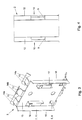
Fig. 2 shows a schematic perspective rear view of the mounting system according to the invention; -
Fig. 3 shows a schematic perspective view of a panel mounting element according to the invention; and -
Fig. 4 shows a schematic front view of a façade mounting element according to the invention. - It is noted that the figures are only schematic representations of a preferred embodiment of the invention and should not be understood to be limiting in any manner. In the figures, identical parts are represented with identical reference numerals.
-
Fig. 1 shows a mountingsystem 1 for mounting a single façade panel to a façade, comprising afaçade mounting element 2 and apanel mounting element 3. - The
façade mounting element 2, also shown inFig. 4 , is here designed as anelongate profile 4 that can be secured by a rear side 5 against a carrier or façade or a façade element. Theprofile 4 can be designed as an extrusion profile, from metal or plastic. Theprofile 4 is usually secured against a façade or a façade element by means of a bolt or screw connection, optionally via a carrier. Other connections are possible, for instance a clamped connection or a glue connection. Instead of a profile, thefaçade mounting element 2 can also be designed as a separate part that is configured for coupling to a singlepanel mounting element 3. Aprofile 4 can be designed to receive a number ofpanel mounting elements 3. - The
panel mounting element 3 is detachably couplable to thefaçade mounting element 2. As a result, thepanel mounting element 3 can be coupled to thefaçade mounting element 2 without the use of further fastening means. - The
panel mounting element 3 is provided with first cooperating elements 5 for cooperation with thefaçade mounting element 2 and second cooperating elements 7 for cooperation with thefaçade mounting element 2. - The first cooperating elements 5 are here designed as a lip 8 which bears on a
bottom side 9 of arecess 10 in thefaçade mounting element 2. Due to the bearing-on, the panel can be borne in vertical direction by thefaçade mounting element 2. Thus, the panel withpanel mounting element 3 can be independently borne by just thefaçade mounting element 2. - The second cooperating elements 7 are here designed as a
bridge element 11 which is configured for cooperation with thefaçade mounting element 2. InFig. 1 and Fig. 2 it can be seen that thebridge element 11 is slid at least partly over aflange 12 of theprofile 4. - The
panel mounting element 3 is further provided with clampingelements 13. The clampingelements 13 are shown inFig. 3 , but are left out inFig. 1 and Fig. 2 for the sake of clarity. The clampingelements 13 are provided with hook elements 14 for hooking into a rear side of a façade panel and thus effecting a force-locked connection with the rear side of a façade panel. Owing to the force-locked connection, thepanel mounting element 3 remains connected to the façade panel. The façade panel withpanel mounting element 3 can be detached from the façade in a simple manner via the detachable coupling of thepanel mounting element 3 with thefaçade mounting element 2. - This can be done while influencing adjacent façade panels only minimally as the
panel mounting element 3 is designed for coupling to one single façade panel. Depending on the size and/or the weight of the façade panel, the façade panel can be provided with several panel mounting elements, for instance side by side or one below the other. - The
panel mounting element 3 is here designed as a substantially plate-shapedbase part 15 which is provided with the first cooperating elements 5, the second cooperating elements 7 and theclamping elements 13. Thebase part 15 is further provided with stiffeningribs 16 for stiffening thebase part 15. - In this exemplary embodiment, the clamping
elements 13 are provided on both sides of thebase part 15 of thepanel mounting element 3, in this case at a top side and a bottom side. Each side is provided with at least two clampingelements 13, here, three clampingelements 13 are provided. The clampingelements 13 are provided with hook elements 14 which are configured for hooking into a groove at a rear side of a façade panel. Through the clampingelements 13, a force-locked connection between thepanel mounting element 3 and the façade panel can be effected, which connection is essentially undetachable. - Preferably, a configuration with hook elements 14 which engage in both sides of such a groove is provided. For instance, in
Fig. 3 ,hook elements 14a can be seen which are directed towards one side and hookelements 14b which are directed towards an opposite side, so that in both sides of such a groove, a hooking connection can be effected. As the hook elements 14 hook into a groove at the rear side of the façade panel, a force-locked connection can be effected which is hidden from view. The façade panel is then aesthetically fixedly connected to thepanel mounting element 3. - In order to mount a façade panel to a façade of a building, first, the
façade mounting element 2 is secured against the façade. Then, thepanel mounting element 3 can be detachably coupled to thefaçade mounting element 2. Thebridge element 11 can be passed through therecess 10 to thus be slid over theflange 12. Thepanel mounting element 3 can be slid further upward until astop element 17 of thebridge element 11 abuts against a top side 18 of therecess 10. Thepanel mounting element 3 can be brought further towards thefaçade mounting element 2 until the lip 8 is in therecess 10 and rests on thebottom side 9 of therecess 10. To simplify insertion of thebridge element 11 in therecess 10 and sliding it over theflange 12, thebridge element 11 is provided with an obliquely projectinginsertion lip 19. - Alternatively, the
panel mounting element 3 can be coupled in advance to thefaçade mounting element 2. This pre-assembly can be carried out, for instance, in a closed space, for instance a factory, free of the influences of wind and weather. Thefaçade mounting element 2 with the fittedpanel mounting element 3 can then be secured against the façade of a building. Thereupon, a façade panel can be pressed against thepanel mounting element 3 to effect a form-locked and/or force-locked connection via theclamping elements 13. - Owing to the
bridge element 11, during use, thepanel mounting element 3 is secured against detaching in sideward direction and in a direction away from thefaçade mounting element 2. Through the lip 8 which bears on thebottom side 9 of therecess 10, during use, thepanel mounting element 3 is secured against detaching in downward direction. Thus, a reliable coupling of thepanel mounting element 3 to thefaçade mounting element 2 is realized. - For detaching the
panel mounting element 3 from thefaçade mounting element 2, the above-mentioned operations can be carried out in reverse order. Thepanel mounting element 3 can be pivoted forward, in a direction away from the building, so that the lip 8 detaches from theside 9. Then, thepanel mounting element 3 can be slid downwards so that thebridge element 11 comes clear of theflange 12 and can be passed through therecess 10. - Through the force-locked connection with the hook elements 14, the façade panel remains fixedly connected to the
panel mounting element 3. The façade panel can thus be elegantly detached from the façade, for instance for maintenance, without damages occurring to the façade panel. A façade panel can then for instance be painted in weather-independent surroundings, instead of on the outer façade of a building. After servicing, the façade panel can simply be coupled to the façade mounting element. - Advantageously, the façade panel is designed in wood or a wood-like or composite material. The façade panel can for instance be designed in a fiber composite material comprising plastic fibers and/or wood fibers. In such a wood, wood-like or composite material, a force-locked connection can be favorably effected.
- Advantageously, the façade panel is provided at the rear side with a groove into which the hook element 14 can hook. The groove can be provided over the width direction of the façade panel, for instance, the groove, after mounting, runs from a left hand side to a right hand side of the façade panel.
- To a façade of a building, different
façade mounting elements 2 can be secured, for instance differentelongated profiles 4 can be attached in upward direction against a façade. By mounting at least twoelongated profiles 4 side by side at a distance from each other against the façade, a façade panel can be mounted against the façade with the aid of twopanel mounting elements 3. Optionally, adjusting possibilities can be provided for setting the façade panel virtually horizontally after mounting. The adjusting elements can be provided in the panel mounting element, or in the façade mounting element or in both. For instance, thebridge element 11 and/or theprofile 12 can be provided with adjusting ridges to achieve a virtually horizontal position of the façade panel after mounting. - Depending on the size and/or the weight of a façade panel and/or the height of mounting and/or the expected weather conditions, a façade panel can be attached with two or more panel mounting elements which engage in the groove at the rear side of the façade panel. Advantageously, the panel mounting elements are in a virtually horizontal line at the rear side of the façade panel in the middle or in a top half of the façade panel, so that the façade panel is, as it were, suspended from the façade.
- The invention is not limited to the exemplary embodiments represented here. The mounting system can be used for mounting a façade panel to an outside façade of a building or an inside façade of a building. Also inside walls can be covered with façade panels by means of the mounting system according to the invention. Diverse variants are possible. All variants are understood to fall within the scope of the following claims.
Claims (19)
- A mounting system for mounting a façade panel to a façade, comprising a façade mounting element and a panel mounting element which is designed for detachable coupling to the façade mounting element, wherein the panel mounting element comprises first cooperating elements for bearing on the façade mounting element and comprises second cooperating elements for a detachable coupling to the façade mounting element, wherein the panel mounting element further comprises clamping elements for connection to the façade panel.
- A mounting system according to claim 1, wherein the first cooperating elements comprise a lip for bearing on a side of a recess in the façade mounting element.
- A mounting system according to claim 1 or 2, wherein the second cooperating elements comprise a bridge element for detachable coupling to the façade mounting element.
- A mounting system according to any one of the preceding claims, wherein the panel mounting element comprises at both sides at least two clamping elements for forming a clamped connection with the façade panel.
- A mounting system according to claim 4, wherein the clamping elements comprise at least one hook element for hooking into a groove of the façade panel for forming the clamped connection.
- A mounting system according to claim 4 and 5, wherein the at least two clamping elements are provided with hook elements for hooking in both sides of the groove of the façade panel.
- A mounting system according to any one of the preceding claims, wherein the panel mounting element is provided with stiffening ribs.
- A mounting system according to any one of the preceding claims, wherein the façade mounting element is provided with a number of recesses for receiving panel mounting elements.
- A panel mounting element suitable for use in a mounting system according to any one of claims 1-8.
- A façade mounting element suitable for use in a mounting system according to any one of claims 1-8.
- A set of a panel mounting element according to claim 9 and a façade mounting element according to claim 10.
- A façade element provided with a façade mounting element according to claim 10.
- A façade element according to claim 12, further comprising a panel mounting element according to claim 9.
- A façade element according to claim 13, further coupled to a façade panel.
- A façade panel provided with a panel mounting element according to claim 9.
- A building whose façade is provided with a façade mounting element according to claim 10.
- A building according to claim 16, further comprising a panel mounting element according to claim 9.
- A building according to claim 17, further coupled to a façade panel.
- A method for mounting a façade panel to a façade comprising providing a mounting system according to any one of claims 1-8, further comprising mounting the façade mounting element to the façade, coupling the panel mounting element to the façade mounting element and connecting the façade panel to the panel mounting element.
Priority Applications (1)
| Application Number | Priority Date | Filing Date | Title |
|---|---|---|---|
| PL12154013T PL2484844T3 (en) | 2011-02-04 | 2012-02-06 | Mounting system and mounting method for a facade panel |
Applications Claiming Priority (1)
| Application Number | Priority Date | Filing Date | Title |
|---|---|---|---|
| NL2006136A NL2006136C2 (en) | 2011-02-04 | 2011-02-04 | FIXING SYSTEM FOR A FACADE PANEL. |
Publications (2)
| Publication Number | Publication Date |
|---|---|
| EP2484844A1 true EP2484844A1 (en) | 2012-08-08 |
| EP2484844B1 EP2484844B1 (en) | 2018-09-26 |
Family
ID=45540842
Family Applications (1)
| Application Number | Title | Priority Date | Filing Date |
|---|---|---|---|
| EP12154013.2A Active EP2484844B1 (en) | 2011-02-04 | 2012-02-06 | Mounting system and mounting method for a facade panel |
Country Status (4)
| Country | Link |
|---|---|
| EP (1) | EP2484844B1 (en) |
| ES (1) | ES2693270T3 (en) |
| NL (1) | NL2006136C2 (en) |
| PL (1) | PL2484844T3 (en) |
Cited By (1)
| Publication number | Priority date | Publication date | Assignee | Title |
|---|---|---|---|---|
| EP2816299A3 (en) * | 2013-06-17 | 2015-03-11 | Green One Tec Solar-Industrie GmbH | Mounting clamp |
Citations (4)
| Publication number | Priority date | Publication date | Assignee | Title |
|---|---|---|---|---|
| US2065529A (en) * | 1936-12-29 | Adjustable support | ||
| GB2065529A (en) | 1979-12-14 | 1981-07-01 | Ckd Corp | Apparatus for welding base pins to inserted lead wires of fluorescent lamps |
| WO2004033927A1 (en) | 2002-10-11 | 2004-04-22 | Olfert B.V. | Securing element |
| WO2009130720A1 (en) | 2008-04-22 | 2009-10-29 | Patt Spa | Modular sound insulation wall with panels |
-
2011
- 2011-02-04 NL NL2006136A patent/NL2006136C2/en not_active IP Right Cessation
-
2012
- 2012-02-06 PL PL12154013T patent/PL2484844T3/en unknown
- 2012-02-06 ES ES12154013.2T patent/ES2693270T3/en active Active
- 2012-02-06 EP EP12154013.2A patent/EP2484844B1/en active Active
Patent Citations (4)
| Publication number | Priority date | Publication date | Assignee | Title |
|---|---|---|---|---|
| US2065529A (en) * | 1936-12-29 | Adjustable support | ||
| GB2065529A (en) | 1979-12-14 | 1981-07-01 | Ckd Corp | Apparatus for welding base pins to inserted lead wires of fluorescent lamps |
| WO2004033927A1 (en) | 2002-10-11 | 2004-04-22 | Olfert B.V. | Securing element |
| WO2009130720A1 (en) | 2008-04-22 | 2009-10-29 | Patt Spa | Modular sound insulation wall with panels |
Cited By (1)
| Publication number | Priority date | Publication date | Assignee | Title |
|---|---|---|---|---|
| EP2816299A3 (en) * | 2013-06-17 | 2015-03-11 | Green One Tec Solar-Industrie GmbH | Mounting clamp |
Also Published As
| Publication number | Publication date |
|---|---|
| EP2484844B1 (en) | 2018-09-26 |
| PL2484844T3 (en) | 2019-02-28 |
| ES2693270T3 (en) | 2018-12-10 |
| NL2006136C2 (en) | 2012-08-07 |
Similar Documents
| Publication | Publication Date | Title |
|---|---|---|
| CA2850051C (en) | Solar light roof panel abutment structure | |
| US8769901B2 (en) | Cladding system for building laminates | |
| CN104989024A (en) | Dismounting and mounting type corner suspended ceiling layer and forming method thereof | |
| CN108086571B (en) | Edge-closing drop-stage suspended ceiling | |
| US20080073036A1 (en) | Sunshades and methods of installing sunshades | |
| US20200291659A1 (en) | Profile element and facade system with profile element | |
| CN102704645B (en) | Detachable frameless big glass keel dry-hanging method construction system and construction method | |
| CN107965072B (en) | Mounting structure of unitized curtain wall grille system and unitized curtain wall | |
| EP2484844B1 (en) | Mounting system and mounting method for a facade panel | |
| CN204299105U (en) | Aluminium veneer curtain wall hook system | |
| CN111910873A (en) | Prefabricated wall panel dry hanging system | |
| CN202500243U (en) | Stone pendant and stone curtain wall | |
| CN203977647U (en) | A kind of dry suspension ceramic board curtain wall system | |
| CN210947282U (en) | Mounting structure of assembled fossil fragments partition wall | |
| CN109403532B (en) | Light and shade joint type ceiling system | |
| CN201343844Y (en) | Structural component capable of independently installing and disassembling decorative panel | |
| JP5303722B2 (en) | Ceiling panel fixing device | |
| CN209807969U (en) | Curtain box | |
| GB2543945A (en) | Facade panel mounting system | |
| RU112233U1 (en) | BRACKET FOR FACING THE BUILDING FACADE | |
| RU2005125910A (en) | METHOD OF INSTALLATION OF VENTED FACING OF BUILDINGS AND DESIGN OF FENCING FOR IMPLEMENTATION OF THE METHOD | |
| NL2030441B1 (en) | Fastening assembly for fastening a plurality of façade panels to the face of a building | |
| CN104652667A (en) | Glass unit body device capable of detaching glass from inside | |
| CN203856158U (en) | Ceiling corner enclosure device for dry-hanging stone veneers | |
| RU79917U1 (en) | CONNECTION OF FILLING ELEMENTS OF FRONT CONSTRUCTIONS |
Legal Events
| Date | Code | Title | Description |
|---|---|---|---|
| PUAI | Public reference made under article 153(3) epc to a published international application that has entered the european phase |
Free format text: ORIGINAL CODE: 0009012 |
|
| AK | Designated contracting states |
Kind code of ref document: A1 Designated state(s): AL AT BE BG CH CY CZ DE DK EE ES FI FR GB GR HR HU IE IS IT LI LT LU LV MC MK MT NL NO PL PT RO RS SE SI SK SM TR |
|
| AX | Request for extension of the european patent |
Extension state: BA ME |
|
| 17P | Request for examination filed |
Effective date: 20130121 |
|
| 17Q | First examination report despatched |
Effective date: 20141208 |
|
| STAA | Information on the status of an ep patent application or granted ep patent |
Free format text: STATUS: EXAMINATION IS IN PROGRESS |
|
| GRAP | Despatch of communication of intention to grant a patent |
Free format text: ORIGINAL CODE: EPIDOSNIGR1 |
|
| STAA | Information on the status of an ep patent application or granted ep patent |
Free format text: STATUS: GRANT OF PATENT IS INTENDED |
|
| INTG | Intention to grant announced |
Effective date: 20180202 |
|
| GRAJ | Information related to disapproval of communication of intention to grant by the applicant or resumption of examination proceedings by the epo deleted |
Free format text: ORIGINAL CODE: EPIDOSDIGR1 |
|
| STAA | Information on the status of an ep patent application or granted ep patent |
Free format text: STATUS: EXAMINATION IS IN PROGRESS |
|
| INTC | Intention to grant announced (deleted) | ||
| GRAP | Despatch of communication of intention to grant a patent |
Free format text: ORIGINAL CODE: EPIDOSNIGR1 |
|
| STAA | Information on the status of an ep patent application or granted ep patent |
Free format text: STATUS: GRANT OF PATENT IS INTENDED |
|
| INTG | Intention to grant announced |
Effective date: 20180629 |
|
| GRAS | Grant fee paid |
Free format text: ORIGINAL CODE: EPIDOSNIGR3 |
|
| GRAA | (expected) grant |
Free format text: ORIGINAL CODE: 0009210 |
|
| STAA | Information on the status of an ep patent application or granted ep patent |
Free format text: STATUS: THE PATENT HAS BEEN GRANTED |
|
| AK | Designated contracting states |
Kind code of ref document: B1 Designated state(s): AL AT BE BG CH CY CZ DE DK EE ES FI FR GB GR HR HU IE IS IT LI LT LU LV MC MK MT NL NO PL PT RO RS SE SI SK SM TR |
|
| REG | Reference to a national code |
Ref country code: GB Ref legal event code: FG4D |
|
| REG | Reference to a national code |
Ref country code: CH Ref legal event code: EP |
|
| REG | Reference to a national code |
Ref country code: AT Ref legal event code: REF Ref document number: 1046203 Country of ref document: AT Kind code of ref document: T Effective date: 20181015 |
|
| REG | Reference to a national code |
Ref country code: IE Ref legal event code: FG4D |
|
| REG | Reference to a national code |
Ref country code: DE Ref legal event code: R096 Ref document number: 602012051442 Country of ref document: DE |
|
| REG | Reference to a national code |
Ref country code: ES Ref legal event code: FG2A Ref document number: 2693270 Country of ref document: ES Kind code of ref document: T3 Effective date: 20181210 |
|
| REG | Reference to a national code |
Ref country code: NL Ref legal event code: FP |
|
| REG | Reference to a national code |
Ref country code: NO Ref legal event code: T2 Effective date: 20180926 |
|
| REG | Reference to a national code |
Ref country code: SE Ref legal event code: TRGR |
|
| PG25 | Lapsed in a contracting state [announced via postgrant information from national office to epo] |
Ref country code: FI Free format text: LAPSE BECAUSE OF FAILURE TO SUBMIT A TRANSLATION OF THE DESCRIPTION OR TO PAY THE FEE WITHIN THE PRESCRIBED TIME-LIMIT Effective date: 20180926 Ref country code: LT Free format text: LAPSE BECAUSE OF FAILURE TO SUBMIT A TRANSLATION OF THE DESCRIPTION OR TO PAY THE FEE WITHIN THE PRESCRIBED TIME-LIMIT Effective date: 20180926 Ref country code: GR Free format text: LAPSE BECAUSE OF FAILURE TO SUBMIT A TRANSLATION OF THE DESCRIPTION OR TO PAY THE FEE WITHIN THE PRESCRIBED TIME-LIMIT Effective date: 20181227 Ref country code: BG Free format text: LAPSE BECAUSE OF FAILURE TO SUBMIT A TRANSLATION OF THE DESCRIPTION OR TO PAY THE FEE WITHIN THE PRESCRIBED TIME-LIMIT Effective date: 20181226 Ref country code: RS Free format text: LAPSE BECAUSE OF FAILURE TO SUBMIT A TRANSLATION OF THE DESCRIPTION OR TO PAY THE FEE WITHIN THE PRESCRIBED TIME-LIMIT Effective date: 20180926 |
|
| REG | Reference to a national code |
Ref country code: LT Ref legal event code: MG4D |
|
| PG25 | Lapsed in a contracting state [announced via postgrant information from national office to epo] |
Ref country code: LV Free format text: LAPSE BECAUSE OF FAILURE TO SUBMIT A TRANSLATION OF THE DESCRIPTION OR TO PAY THE FEE WITHIN THE PRESCRIBED TIME-LIMIT Effective date: 20180926 Ref country code: AL Free format text: LAPSE BECAUSE OF FAILURE TO SUBMIT A TRANSLATION OF THE DESCRIPTION OR TO PAY THE FEE WITHIN THE PRESCRIBED TIME-LIMIT Effective date: 20180926 Ref country code: HR Free format text: LAPSE BECAUSE OF FAILURE TO SUBMIT A TRANSLATION OF THE DESCRIPTION OR TO PAY THE FEE WITHIN THE PRESCRIBED TIME-LIMIT Effective date: 20180926 |
|
| REG | Reference to a national code |
Ref country code: AT Ref legal event code: MK05 Ref document number: 1046203 Country of ref document: AT Kind code of ref document: T Effective date: 20180926 |
|
| PG25 | Lapsed in a contracting state [announced via postgrant information from national office to epo] |
Ref country code: IS Free format text: LAPSE BECAUSE OF FAILURE TO SUBMIT A TRANSLATION OF THE DESCRIPTION OR TO PAY THE FEE WITHIN THE PRESCRIBED TIME-LIMIT Effective date: 20190126 Ref country code: EE Free format text: LAPSE BECAUSE OF FAILURE TO SUBMIT A TRANSLATION OF THE DESCRIPTION OR TO PAY THE FEE WITHIN THE PRESCRIBED TIME-LIMIT Effective date: 20180926 Ref country code: AT Free format text: LAPSE BECAUSE OF FAILURE TO SUBMIT A TRANSLATION OF THE DESCRIPTION OR TO PAY THE FEE WITHIN THE PRESCRIBED TIME-LIMIT Effective date: 20180926 Ref country code: CZ Free format text: LAPSE BECAUSE OF FAILURE TO SUBMIT A TRANSLATION OF THE DESCRIPTION OR TO PAY THE FEE WITHIN THE PRESCRIBED TIME-LIMIT Effective date: 20180926 Ref country code: IT Free format text: LAPSE BECAUSE OF FAILURE TO SUBMIT A TRANSLATION OF THE DESCRIPTION OR TO PAY THE FEE WITHIN THE PRESCRIBED TIME-LIMIT Effective date: 20180926 Ref country code: RO Free format text: LAPSE BECAUSE OF FAILURE TO SUBMIT A TRANSLATION OF THE DESCRIPTION OR TO PAY THE FEE WITHIN THE PRESCRIBED TIME-LIMIT Effective date: 20180926 |
|
| PG25 | Lapsed in a contracting state [announced via postgrant information from national office to epo] |
Ref country code: SM Free format text: LAPSE BECAUSE OF FAILURE TO SUBMIT A TRANSLATION OF THE DESCRIPTION OR TO PAY THE FEE WITHIN THE PRESCRIBED TIME-LIMIT Effective date: 20180926 Ref country code: PT Free format text: LAPSE BECAUSE OF FAILURE TO SUBMIT A TRANSLATION OF THE DESCRIPTION OR TO PAY THE FEE WITHIN THE PRESCRIBED TIME-LIMIT Effective date: 20190126 Ref country code: SK Free format text: LAPSE BECAUSE OF FAILURE TO SUBMIT A TRANSLATION OF THE DESCRIPTION OR TO PAY THE FEE WITHIN THE PRESCRIBED TIME-LIMIT Effective date: 20180926 |
|
| REG | Reference to a national code |
Ref country code: DE Ref legal event code: R097 Ref document number: 602012051442 Country of ref document: DE |
|
| PG25 | Lapsed in a contracting state [announced via postgrant information from national office to epo] |
Ref country code: DK Free format text: LAPSE BECAUSE OF FAILURE TO SUBMIT A TRANSLATION OF THE DESCRIPTION OR TO PAY THE FEE WITHIN THE PRESCRIBED TIME-LIMIT Effective date: 20180926 |
|
| PLBE | No opposition filed within time limit |
Free format text: ORIGINAL CODE: 0009261 |
|
| STAA | Information on the status of an ep patent application or granted ep patent |
Free format text: STATUS: NO OPPOSITION FILED WITHIN TIME LIMIT |
|
| 26N | No opposition filed |
Effective date: 20190627 |
|
| REG | Reference to a national code |
Ref country code: CH Ref legal event code: PL |
|
| PG25 | Lapsed in a contracting state [announced via postgrant information from national office to epo] |
Ref country code: SI Free format text: LAPSE BECAUSE OF FAILURE TO SUBMIT A TRANSLATION OF THE DESCRIPTION OR TO PAY THE FEE WITHIN THE PRESCRIBED TIME-LIMIT Effective date: 20180926 Ref country code: MC Free format text: LAPSE BECAUSE OF FAILURE TO SUBMIT A TRANSLATION OF THE DESCRIPTION OR TO PAY THE FEE WITHIN THE PRESCRIBED TIME-LIMIT Effective date: 20180926 |
|
| REG | Reference to a national code |
Ref country code: IE Ref legal event code: MM4A |
|
| PG25 | Lapsed in a contracting state [announced via postgrant information from national office to epo] |
Ref country code: CH Free format text: LAPSE BECAUSE OF NON-PAYMENT OF DUE FEES Effective date: 20190228 Ref country code: LI Free format text: LAPSE BECAUSE OF NON-PAYMENT OF DUE FEES Effective date: 20190228 |
|
| PG25 | Lapsed in a contracting state [announced via postgrant information from national office to epo] |
Ref country code: IE Free format text: LAPSE BECAUSE OF NON-PAYMENT OF DUE FEES Effective date: 20190206 |
|
| PG25 | Lapsed in a contracting state [announced via postgrant information from national office to epo] |
Ref country code: TR Free format text: LAPSE BECAUSE OF FAILURE TO SUBMIT A TRANSLATION OF THE DESCRIPTION OR TO PAY THE FEE WITHIN THE PRESCRIBED TIME-LIMIT Effective date: 20180926 |
|
| PG25 | Lapsed in a contracting state [announced via postgrant information from national office to epo] |
Ref country code: MT Free format text: LAPSE BECAUSE OF NON-PAYMENT OF DUE FEES Effective date: 20190206 |
|
| PG25 | Lapsed in a contracting state [announced via postgrant information from national office to epo] |
Ref country code: CY Free format text: LAPSE BECAUSE OF FAILURE TO SUBMIT A TRANSLATION OF THE DESCRIPTION OR TO PAY THE FEE WITHIN THE PRESCRIBED TIME-LIMIT Effective date: 20180926 |
|
| PG25 | Lapsed in a contracting state [announced via postgrant information from national office to epo] |
Ref country code: HU Free format text: LAPSE BECAUSE OF FAILURE TO SUBMIT A TRANSLATION OF THE DESCRIPTION OR TO PAY THE FEE WITHIN THE PRESCRIBED TIME-LIMIT; INVALID AB INITIO Effective date: 20120206 |
|
| PG25 | Lapsed in a contracting state [announced via postgrant information from national office to epo] |
Ref country code: MK Free format text: LAPSE BECAUSE OF FAILURE TO SUBMIT A TRANSLATION OF THE DESCRIPTION OR TO PAY THE FEE WITHIN THE PRESCRIBED TIME-LIMIT Effective date: 20180926 |
|
| P01 | Opt-out of the competence of the unified patent court (upc) registered |
Effective date: 20230525 |
|
| PGFP | Annual fee paid to national office [announced via postgrant information from national office to epo] |
Ref country code: ES Payment date: 20250331 Year of fee payment: 14 |
|
| PGFP | Annual fee paid to national office [announced via postgrant information from national office to epo] |
Ref country code: LU Payment date: 20260218 Year of fee payment: 15 Ref country code: NL Payment date: 20260218 Year of fee payment: 15 |
|
| PGFP | Annual fee paid to national office [announced via postgrant information from national office to epo] |
Ref country code: SE Payment date: 20260218 Year of fee payment: 15 |
|
| PGFP | Annual fee paid to national office [announced via postgrant information from national office to epo] |
Ref country code: GB Payment date: 20260219 Year of fee payment: 15 |
|
| PGFP | Annual fee paid to national office [announced via postgrant information from national office to epo] |
Ref country code: NO Payment date: 20260220 Year of fee payment: 15 Ref country code: DE Payment date: 20260218 Year of fee payment: 15 |
|
| PGFP | Annual fee paid to national office [announced via postgrant information from national office to epo] |
Ref country code: BE Payment date: 20260218 Year of fee payment: 15 |
|
| PGFP | Annual fee paid to national office [announced via postgrant information from national office to epo] |
Ref country code: FR Payment date: 20260218 Year of fee payment: 15 |
|
| PGFP | Annual fee paid to national office [announced via postgrant information from national office to epo] |
Ref country code: PL Payment date: 20260122 Year of fee payment: 15 |