EP2484814A1 - Quartz glass crucible for pulling up silicon single crystal and method for producing the same - Google Patents
Quartz glass crucible for pulling up silicon single crystal and method for producing the same Download PDFInfo
- Publication number
- EP2484814A1 EP2484814A1 EP20120166336 EP12166336A EP2484814A1 EP 2484814 A1 EP2484814 A1 EP 2484814A1 EP 20120166336 EP20120166336 EP 20120166336 EP 12166336 A EP12166336 A EP 12166336A EP 2484814 A1 EP2484814 A1 EP 2484814A1
- Authority
- EP
- European Patent Office
- Prior art keywords
- quartz glass
- melt
- surface level
- crucible
- pulling
- Prior art date
- Legal status (The legal status is an assumption and is not a legal conclusion. Google has not performed a legal analysis and makes no representation as to the accuracy of the status listed.)
- Withdrawn
Links
Images


Classifications
-
- C—CHEMISTRY; METALLURGY
- C30—CRYSTAL GROWTH
- C30B—SINGLE-CRYSTAL GROWTH; UNIDIRECTIONAL SOLIDIFICATION OF EUTECTIC MATERIAL OR UNIDIRECTIONAL DEMIXING OF EUTECTOID MATERIAL; REFINING BY ZONE-MELTING OF MATERIAL; PRODUCTION OF A HOMOGENEOUS POLYCRYSTALLINE MATERIAL WITH DEFINED STRUCTURE; SINGLE CRYSTALS OR HOMOGENEOUS POLYCRYSTALLINE MATERIAL WITH DEFINED STRUCTURE; AFTER-TREATMENT OF SINGLE CRYSTALS OR A HOMOGENEOUS POLYCRYSTALLINE MATERIAL WITH DEFINED STRUCTURE; APPARATUS THEREFOR
- C30B15/00—Single-crystal growth by pulling from a melt, e.g. Czochralski method
- C30B15/10—Crucibles or containers for supporting the melt
-
- C—CHEMISTRY; METALLURGY
- C03—GLASS; MINERAL OR SLAG WOOL
- C03B—MANUFACTURE, SHAPING, OR SUPPLEMENTARY PROCESSES
- C03B19/00—Other methods of shaping glass
- C03B19/09—Other methods of shaping glass by fusing powdered glass in a shaping mould
- C03B19/095—Other methods of shaping glass by fusing powdered glass in a shaping mould by centrifuging, e.g. arc discharge in rotating mould
-
- C—CHEMISTRY; METALLURGY
- C30—CRYSTAL GROWTH
- C30B—SINGLE-CRYSTAL GROWTH; UNIDIRECTIONAL SOLIDIFICATION OF EUTECTIC MATERIAL OR UNIDIRECTIONAL DEMIXING OF EUTECTOID MATERIAL; REFINING BY ZONE-MELTING OF MATERIAL; PRODUCTION OF A HOMOGENEOUS POLYCRYSTALLINE MATERIAL WITH DEFINED STRUCTURE; SINGLE CRYSTALS OR HOMOGENEOUS POLYCRYSTALLINE MATERIAL WITH DEFINED STRUCTURE; AFTER-TREATMENT OF SINGLE CRYSTALS OR A HOMOGENEOUS POLYCRYSTALLINE MATERIAL WITH DEFINED STRUCTURE; APPARATUS THEREFOR
- C30B29/00—Single crystals or homogeneous polycrystalline material with defined structure characterised by the material or by their shape
- C30B29/02—Elements
- C30B29/06—Silicon
-
- Y—GENERAL TAGGING OF NEW TECHNOLOGICAL DEVELOPMENTS; GENERAL TAGGING OF CROSS-SECTIONAL TECHNOLOGIES SPANNING OVER SEVERAL SECTIONS OF THE IPC; TECHNICAL SUBJECTS COVERED BY FORMER USPC CROSS-REFERENCE ART COLLECTIONS [XRACs] AND DIGESTS
- Y10—TECHNICAL SUBJECTS COVERED BY FORMER USPC
- Y10T—TECHNICAL SUBJECTS COVERED BY FORMER US CLASSIFICATION
- Y10T117/00—Single-crystal, oriented-crystal, and epitaxy growth processes; non-coating apparatus therefor
- Y10T117/10—Apparatus
-
- Y—GENERAL TAGGING OF NEW TECHNOLOGICAL DEVELOPMENTS; GENERAL TAGGING OF CROSS-SECTIONAL TECHNOLOGIES SPANNING OVER SEVERAL SECTIONS OF THE IPC; TECHNICAL SUBJECTS COVERED BY FORMER USPC CROSS-REFERENCE ART COLLECTIONS [XRACs] AND DIGESTS
- Y10—TECHNICAL SUBJECTS COVERED BY FORMER USPC
- Y10T—TECHNICAL SUBJECTS COVERED BY FORMER US CLASSIFICATION
- Y10T117/00—Single-crystal, oriented-crystal, and epitaxy growth processes; non-coating apparatus therefor
- Y10T117/10—Apparatus
- Y10T117/1024—Apparatus for crystallization from liquid or supercritical state
- Y10T117/1032—Seed pulling
-
- Y—GENERAL TAGGING OF NEW TECHNOLOGICAL DEVELOPMENTS; GENERAL TAGGING OF CROSS-SECTIONAL TECHNOLOGIES SPANNING OVER SEVERAL SECTIONS OF THE IPC; TECHNICAL SUBJECTS COVERED BY FORMER USPC CROSS-REFERENCE ART COLLECTIONS [XRACs] AND DIGESTS
- Y10—TECHNICAL SUBJECTS COVERED BY FORMER USPC
- Y10T—TECHNICAL SUBJECTS COVERED BY FORMER US CLASSIFICATION
- Y10T117/00—Single-crystal, oriented-crystal, and epitaxy growth processes; non-coating apparatus therefor
- Y10T117/10—Apparatus
- Y10T117/1024—Apparatus for crystallization from liquid or supercritical state
- Y10T117/1032—Seed pulling
- Y10T117/1052—Seed pulling including a sectioned crucible [e.g., double crucible, baffle]
Definitions
- the present invention relates to a quartz glass crucible for pulling up a silicon single crystal and a process for producing the same.
- CZ method Czochralski method
- This CZ method is a method in which polycrystal silicon is melted in a crucible made of a quartz glass, a seed crystal of a silicon single crystal is dipped into this silicon melt and the seed crystal is gradually pulled up while rotating the crucible, to grow a silicon single crystal by employing a seed crystal as a nucleus. It is necessary that the single crystal produced by the above-mentioned CZ method is of high purity and is also enabled to produce a silicon wafer in high yield.
- a quartz glass crucible to be used in the production a quartz glass crucible having a two layer structure comprising a transparent inner layer that does not contain bubbles and an opaque outer layer that contains bubbles is generally used.
- the above-mentioned brown ring occurs by employing, as a nucleus, a minute scratch on the glass surface, a portion of crystalline residue, which is an undissolved residue of a raw material powder, a defect of the glass structure or the like.
- a portion of crystalline residue which is an undissolved residue of a raw material powder, a defect of the glass structure or the like.
- melting is performed at a high temperature for a long time for reducing a crystalline residual component, or as described in Japanese Patent Nos. 2811290 and 2933404 , an amorphous synthetic powder is used as a raw material powder for forming the inner surface thereof.
- a synthetic quartz glass made of the above-mentioned amorphous synthetic powder there are advantages in that the content of impurities can be made extremely low and the occurrence of surface roughness or brown rings on the inner surface of a crucible in accordance with the pulling up of a silicon single crystal can be reduced.
- a transparent inner layer is composed of a synthetic quartz glass and an outer layer is composed of an opaque quartz glass made of natural quartz glass
- the physical properties vary widely between the transparent inner layer and the outer layer such as the difference between the fact that one is transparent and the other is opaque and the difference between the fact that one is made of a synthetic substance and the other is made of a natural one, therefore distortion is generated at the boundary between both layers.
- a crucible comprising a transparent inner layer made of a synthetic quartz glass had a drawback in that when a polysilicon was melted, the surface of the melt was liable to vibrate compared with a crucible comprising a transparent inner layer made of natural quartz glass.
- the present inventors have continued intensive studies in order to overcome the above-mentioned drawbacks, and as a result, they found that the yield in the pulling up of a single crystal is deeply related to the inner surface of the bent portion of a quartz glass crucible and vibration occurring on the surface of a silicon melt is deeply related to the inner surface of the straight body portion thereof, and a high yield in the pulling up of a silicon single crystal can be achieved by forming the inner surface at least at the vicinity of the bent portion in a quartz glass crucible to be used for pulling up a silicon single crystal with a transparent layer made of a synthetic quartz glass, in addition, a problem such as deformation or peel-off of the inner layer can be solved by interposing a transparent layer made of natural quartz glass between a transparent layer made of a synthetic quartz glass and an opaque outer layer made of natural quartz glass, further, the occurrence of vibration on the surface of a silicon melt can be suppressed by forming the inner surface of the straight body portion with natural quartz glass or with a very thin synthetic quartz glass layer
- an object of the present invention is to provide a quartz glass crucible for pulling up a silicon single crystal in which the occurrence of vibration on the surface of a melt is suppressed, the occurrence rate of surface roughness on the inner surface of a crucible is low even in a long time operation, and a silicon single crystal can be stably pulled up.
- an object of the present invention is to provide a method that can produce a quartz glass crucible for pulling up a silicon single crystal having the above-mentioned excellent properties at low cost.
- the present invention relates to a quartz glass crucible for pulling up a silicon single crystal, which has an opaque outer layer made of natural quartz glass and a transparent layer formed on the inside thereof, in which the number of brown rings per unit area (cm 2 ) observed in the region extending from the initial surface level of a silicon melt to 0.3 M in terms of a length M from the initial surface level of the silicon melt to the surface level of the remaining melt after pulling up a single crystal measured along the inner surface of the quartz glass crucible is at least 1.8-fold greater than 15 brown rings observed in the range up to 0.3 M above the surface level of the remaining melt.
- the present invention secondly relates to a method for producing the above-mentioned quartz glass crucible for pulling up a silicon single crystal.
- the quartz glass crucible of the present invention is, as described above, a quartz glass crucible for pulling up a silicon single crystal, which has an opaque outer layer made of natural quartz glass and a transparent layer formed on the inside thereof, in which the number of brown rings per unit area (cm 2 ) observed in the region extending from the initial surface level of a silicon melt to 0.3 M in terms of a length M from the initial surface level of the silicon melt to the surface level of the remaining melt after pulling up a single crystal measured along the inner surface of the quartz glass crucible is at least 1.8-fold, preferably at least 2.5-fold greater than the number of brown rings observed in the range up to 0.3 M above the surface level of the remaining melt.
- the above-mentioned brown ring is a cristobalite brown ring as described above, and in the initial stage of the occurrence thereof, as shown in Fig. 3(a) , there is no cristobalite layer or even if there is, it is a very thin layer.
- the brown ring expands its size and a crystalline texture emerges as shown in Fig. 3(b) . Pulling up of a single crystal is further continued, and when the reaction between the silicon melt and the crucible proceeds, the portion encircled by the brown ring as shown in Fig.
- FIG. 3(c) is gradually eroded to become a rough glass dissolving surface (amorphous).
- Fig. 3 17 indicates the inner surface of a crucible, 18 indicates a brown ring, 19 indicates a crystalline texture, and 20 indicates a glass dissolving surface. Once this glass dissolving surface emerges, dislocations are liable to be generated in a silicon single crystal, and the rate of single crystallization is decreased.
- the above-mentioned number of brown rings is the number per unit area (cm 2 ) calculated by dividing the counted number of brown rings observed in arbitrary three locations with a width of 10 cm in the circumferential direction of the crucible by the measured area.
- brown rings are fused to each other in some cases.
- the area per one brown ring is calculated from the average size of a single brown ring observed in the measured range, the value obtained by dividing the area of the fused portion by the area per one brown ring is defined as the number of brown rings in the fused portion.
- the number of brown rings may slightly vary depending on the conditions of pulling up a single crystal even if the same crucible is used, however, the number of brown rings per unit area (cm 2 ) observed in the region extending from the initial surface level of a silicon melt to 0.3 M in terms of a length M from the initial surface level of the silicon melt to the surface level of the remaining melt after pulling up a single crystal measured along the inner surface of the crucible is set to at least 1.8-fold, preferably at least 2.5-fold greater than the number of brown rings observed in the range up to 0.3 M above the surface level of the remaining melt.
- the number of brown rings observed in the region extending from the initial surface level of the melt to 0.3 M is from 2.0 to 5.0/cm 2 , vibration occurring on the surface of the silicon melt can be surely suppressed.
- the number of brown rings observed in the range up to 0.3 M above the surface level of the remaining melt is from 0.02 to 0.9/cm 2 or less, the yield of silicon single crystal becomes a high level.
- melt back is carried out in come cases, however, when this melt back is carried out or multiple pulling up in which several single crystals are pulled up from one crucible is carried out, the number of brown rings is increased, fusion of brown rings proceeds, and calculation of the number becomes difficult.
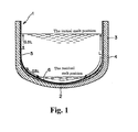
- Fig. 1 1 indicates a quartz glass crucible
- 2 indicates a bottom of the crucible
- 3 indicates a straight body portion
- 4 indicates an opaque outer layer made of a synthetic quartz glass
- 5 indicates a transparent layer made of natural quartz glass
- 6 indicates a transparent layer made of a synthetic quartz glass.
- the quartz glass crucible of the present invention is, as shown in Fig.
- a quartz glass crucible having an opaque layer made of natural quartz glass and a transparent layer made of quartz glass formed on the inside thereof, in which the inner surface of the crucible in the region extending from the initial surface level of the melt to 0.3 M is formed with a transparent layer made of natural quartz glass or a mixture of natural and synthetic quartz glasses, the inner surface of the crucible in the range up to 0.3 M above the surface level of the remaining melt is formed with a transparent layer made of a synthetic quartz glass, and the inner surface of the crucible in the range other than above is formed with a transparent layer made of any of natural quartz glass, a mixture of natural and synthetic quartz glasses and a synthetic quartz glass.
- the above-mentioned quartz glass crucible is produced by using an apparatus shown in Fig.
- the method for producing the quartz glass crucible it can also be produced by a method in which the entire inner layer of the crucible is composed of a synthetic quartz glass, the inner surface of the crucible in the region extending from the initial surface level of the melt to 0.3 M is subjected to an etching treatment or a sandblast process to make minute scratches, and the number of brown rings is increased to adjust the ratio of the number of brown rings in the region extending from the initial surface level of the melt to 0.3 M to the number of brown rings in the range up to 0.3 M above the surface level of the remaining melt to at least 1.8-fold, preferably at least 2.5-fold .
- the inner cavity of the opaque outer layer 4 was made a high temperature atmosphere 16 by the arc electrode 14 while rotating the mold 8, and then natural silica powder was fed at 100 g/min from a silica powder feeding nozzle 15, whereby a transparent layer 5 with a thickness of 0.9 to 2 mm made of natural quartz glass was fused and integrated to the inner surface of the opaque outer layer 4.
- a synthetic silica powder was fed at 100 g/min from the silica powder feeding nozzle 15, whereby a transparent layer 6 made of a synthetic quartz glass was fused and integrated to the above-mentioned transparent layer at a thickness of 0.5 to 1.2 mm, at a thickness of 0.2 to 0.5 mm, and at a thickness of 0.1 to 0.2 mm in the range up to 0.55 L, in the region extending from 0.55 to 0.6 L and in the region extending from 0.6 to 1.0 L, respectively in terms of a distance (L) from the center of the bottom of the transparent layer to the upper end face along the inner surface of the crucible.
- the diameter of the obtained quartz glass crucible was 24 inches, and the average OH group concentration C C in the opaque outer layer 4 made of natural quartz glass was 40 ppm, the average OH group concentration C B in the transparent layer 5 made of natural quartz glass was 110 ppm and the average OH group concentration C A in the transparent layer 6 made of a synthetic quartz glass was 220 ppm.
- N 5 by the CZ method
- Example 1 the transparent layer 5 made of natural quartz glass and the transparent layer 6 made of a synthetic quartz glass, which form the inner surface of a quartz glass crucible, were fused and integrated so as to have a thickness shown in Table 1, respectively, whereby a 24-inch quartz glass crucible was produced.
- the average OH group concentration in each layer of the produced quartz glass crucible was as shown in Table 1.
- pulling up of a silicon single crystal was carried out in the same manner as in Example 1. The results are shown in Table 1.
- Example 1 the transparent layer 5 made of natural quartz glass and the transparent layer 6 made of a synthetic quartz glass, which form the inner surface of a quartz glass crucible, were fused and integrated so as to have a thickness shown in Table 2, respectively, whereby a 24-inch quartz glass crucible was produced.
- the average OH group concentration in each layer of the produced quartz glass crucible was as shown in Table 2.
- pulling up of a silicon single crystal was carried out in the same manner as in Example 1. The results are shown in Table 2.
- Example 2 Example 3
- Example 4 Transparent layer made of synthetic quartz glass Thickness [mm] 0 to 0.55 L: 1 to 3; 0.55 to 0.6 L: 0.2 to 1 0.6 to 1 L: 0.1 to 0.2 0 to 0.1 L: 0; 0.1 to 0.15 L: 0 to 0.3: 0.15 to 0.55 L: 0.3 to 1.2; 0.55 to 0.6 L: 0.2 to 0.4; 0.6 to 1 L: 0.1 to 0.2 0 to 0.55 L: 0.3 to 0.8; 0.55 to 0.6 L: 0 to 0.3; 0.6 to 1 L: 0 0 to 0.55 L: 0.3 to 0.8; 0.55 to 0.6 L: 0 to 0.03; 0.6 to 1 L: 0 OH group 220 ppm 220 ppm 150 ppm 150 ppm Transparent inner layer made of natural quartz glass Thickness 0.7 to 1 mm 0.9 to 2 mm 1 to 3 mm 1 to 3 mm OH group 110 ppm 110 ppm 80 ppm
- a transparent layer made of synthetic quartz glass is not present at the bottom, however the yield is favorable. There is no problem. There was no problem with the performance, however, the shape is slightly deformed and there is some concern.
- a synthetic silica powder was fed at 100 g/min from a silica powder feeding device 15, and a transparent layer made of a synthetic quartz glass was fused and integrated to the entire inner surface of the opaque outer layer 4, whereby a quartz glass crucible with an outer diameter of 22 inches was produced. Further, the region which is the upper straight body portion 3 of the above-mentioned crucible and in the region extending from the initial surface level of the silicon melt to 0.35 M was subjected to an etching treatment with 50% HF for 30 minutes as well as a standard HF washing. By using this quartz glass crucible, pulling up of a silicon single crystal was carried out by the CZ method. The results of the pulling up of a silicon single crystal and the results of measuring the number of brown rings on the inner surface of the crucible are shown in Table 3.
- a synthetic silica powder was fed at 100 g/min from a silica powder feeding device 15, and a transparent layer made of a synthetic quartz glass was fused and integrated to the entire inner surface of the opaque outer layer 4, whereby a quartz glass crucible with an outer diameter of 22 inches was produced.
- a quartz glass crucible By using this quartz glass crucible, pulling up of a silicon single crystal was carried out by the CZ method. The results of the pulling up of a silicon single crystal and the results of measuring the number of brown rings on the inner surface of the crucible are shown in Table 3.
- the quartz glass crucible of the present invention is useful as a quartz glass crucible for pulling up a silicon single crystal because vibration does not occur on the surface of a silicon melt, surface roughness or peel-off of the inner layer does not occur, and even if it is used for a long time, surface roughness of the inner surface or peel-off of the inner layer does not occur, and pulling up of a silicon single crystal can be stably carried out for a long time.
Landscapes
- Chemical & Material Sciences (AREA)
- Engineering & Computer Science (AREA)
- Materials Engineering (AREA)
- Organic Chemistry (AREA)
- Crystallography & Structural Chemistry (AREA)
- Metallurgy (AREA)
- Manufacturing & Machinery (AREA)
- Crystals, And After-Treatments Of Crystals (AREA)
- Glass Melting And Manufacturing (AREA)
Abstract
Description
- The present invention relates to a quartz glass crucible for pulling up a silicon single crystal and a process for producing the same.
- A method which is called Czochralski method (CZ method) has heretofore widely been adopted in production of silicon single crystals. This CZ method is a method in which polycrystal silicon is melted in a crucible made of a quartz glass, a seed crystal of a silicon single crystal is dipped into this silicon melt and the seed crystal is gradually pulled up while rotating the crucible, to grow a silicon single crystal by employing a seed crystal as a nucleus. It is necessary that the single crystal produced by the above-mentioned CZ method is of high purity and is also enabled to produce a silicon wafer in high yield. As for a quartz glass crucible to be used in the production, a quartz glass crucible having a two layer structure comprising a transparent inner layer that does not contain bubbles and an opaque outer layer that contains bubbles is generally used.
- In recent years, as a silicon single crystal is made large in diameter, the time for the operation of pulling up of the single crystal becomes longer and the inner surface thereof contacts a silicon melt at a temperature of 1400°C or higher for a long time. The inner surface thereof reacts with the silicon melt and crystallization occurs in a shallow layer of the inner surface, thereby causing the occurrence of brown cristobalite in the form of ring (hereinafter referred to as a brown ring). In the above-mentioned brown ring, there is no cristobalite layer or even if there is, it is a very thin layer, however, as the operating time elapses, the brown ring expands its size and continues to grow while fusing with each other. Finally, the central portion thereof is eroded to become an uneven glass dissolving surface. Once this glass dissolving surface emerges, dislocations are liable to be generated in a silicon single crystal, which entails inconvenience in the yield in the pulling up of a single crystal. In particular, in order to grow a silicon single crystal for producing a wafer with a large diameter of not smaller than 200 mm, it is necessary to perform the operation in the CZ method for more than 100 hours, whereby the emergence of the above-mentioned glass dissolving surface becomes prominent.
- It is considered that the above-mentioned brown ring occurs by employing, as a nucleus, a minute scratch on the glass surface, a portion of crystalline residue, which is an undissolved residue of a raw material powder, a defect of the glass structure or the like. In order to reduce the number thereof, the condition of the glass surface is maintained good, melting is performed at a high temperature for a long time for reducing a crystalline residual component, or as described in Japanese Patent Nos.
2811290 2933404 JP-A-2001-348294 - The present inventors have continued intensive studies in order to overcome the above-mentioned drawbacks, and as a result, they found that the yield in the pulling up of a single crystal is deeply related to the inner surface of the bent portion of a quartz glass crucible and vibration occurring on the surface of a silicon melt is deeply related to the inner surface of the straight body portion thereof, and a high yield in the pulling up of a silicon single crystal can be achieved by forming the inner surface at least at the vicinity of the bent portion in a quartz glass crucible to be used for pulling up a silicon single crystal with a transparent layer made of a synthetic quartz glass, in addition, a problem such as deformation or peel-off of the inner layer can be solved by interposing a transparent layer made of natural quartz glass between a transparent layer made of a synthetic quartz glass and an opaque outer layer made of natural quartz glass, further, the occurrence of vibration on the surface of a silicon melt can be suppressed by forming the inner surface of the straight body portion with natural quartz glass or with a very thin synthetic quartz glass layer.
- On the other hand, when the number of brown rings occurring on the inner surface of a crucible in the CZ method is reduced, the surface of a silicon melt is liable to vibrate at the time of pulling up a crystal; therefore there is a problem of deterioration of workability. As a solution thereof, it was fount that when the ratio of the number of brown rings occurring in the region extending from the initial surface level of a silicon melt in the pulling up of a single crystal to 0.3 M in terms of a length M from the initial surface level of the silicon melt to the surface level of the remaining melt after pulling up a single crystal measured along the inner surface of a quartz glass crucible to the number of brown rings occurring in the range up to 0.3 M from the surface level of the remaining melt after pulling up is set in a specific range or higher, vibration on the surface of the melt does not occur and the yield in the pulling up of a single crystal becomes high.
- Accordingly, an object of the present invention is to provide a quartz glass crucible for pulling up a silicon single crystal in which the occurrence of vibration on the surface of a melt is suppressed, the occurrence rate of surface roughness on the inner surface of a crucible is low even in a long time operation, and a silicon single crystal can be stably pulled up.
- In addition, an object of the present invention is to provide a method that can produce a quartz glass crucible for pulling up a silicon single crystal having the above-mentioned excellent properties at low cost.
- The present invention relates to a quartz glass crucible for pulling up a silicon single crystal, which has an opaque outer layer made of natural quartz glass and a transparent layer formed on the inside thereof, in which the number of brown rings per unit area (cm2) observed in the region extending from the initial surface level of a silicon melt to 0.3 M in terms of a length M from the initial surface level of the silicon melt to the surface level of the remaining melt after pulling up a single crystal measured along the inner surface of the quartz glass crucible is at least 1.8-fold greater than 15 brown rings observed in the range up to 0.3 M above the surface level of the remaining melt.
- The present invention secondly relates to a method for producing the above-mentioned quartz glass crucible for pulling up a silicon single crystal.
- The quartz glass crucible of the present invention is, as described above, a quartz glass crucible for pulling up a silicon single crystal, which has an opaque outer layer made of natural quartz glass and a transparent layer formed on the inside thereof, in which the number of brown rings per unit area (cm2) observed in the region extending from the initial surface level of a silicon melt to 0.3 M in terms of a length M from the initial surface level of the silicon melt to the surface level of the remaining melt after pulling up a single crystal measured along the inner surface of the quartz glass crucible is at least 1.8-fold, preferably at least 2.5-fold greater than the number of brown rings observed in the range up to 0.3 M above the surface level of the remaining melt. The above-mentioned brown ring is a cristobalite brown ring as described above, and in the initial stage of the occurrence thereof, as shown in
Fig. 3(a) , there is no cristobalite layer or even if there is, it is a very thin layer. As the operating time of pulling up a single crystal elapses, that is, as the time of contacting a crucible with a silicon melt is increased, the brown ring expands its size and a crystalline texture emerges as shown inFig. 3(b) . Pulling up of a single crystal is further continued, and when the reaction between the silicon melt and the crucible proceeds, the portion encircled by the brown ring as shown inFig. 3(c) is gradually eroded to become a rough glass dissolving surface (amorphous). InFig. 3 , 17 indicates the inner surface of a crucible, 18 indicates a brown ring, 19 indicates a crystalline texture, and 20 indicates a glass dissolving surface. Once this glass dissolving surface emerges, dislocations are liable to be generated in a silicon single crystal, and the rate of single crystallization is decreased. - The above-mentioned number of brown rings is the number per unit area (cm2) calculated by dividing the counted number of brown rings observed in arbitrary three locations with a width of 10 cm in the circumferential direction of the crucible by the measured area. In the vicinity of the remaining melt which is contacted with the silicon melt in the crucible for a long time and on which a brown ring is liable to grow, brown rings are fused to each other in some cases. In this case, however, the area per one brown ring is calculated from the average size of a single brown ring observed in the measured range, the value obtained by dividing the area of the fused portion by the area per one brown ring is defined as the number of brown rings in the fused portion.
- In the quartz glass crucible to be used in the CZ method, vibration on the surface of a silicon melt in the CZ method occurs particularly frequently in the range where the surface level of the melt is from the initial surface level of the melt to 0.3 M, however, by increasing the number of brown rings only in the range, the above-mentioned vibration occurring on the surface of a silicon melt can be suppressed. In addition, since the above-mentioned range is contacted with the silicon melt for a short time, a brown ring is small in size and in a state as shown in
Fig. 3a , and a glass dissolving surface does not occur, therefore, even if the number of brown rings is increased, there is no effect on the yield in the pulling up of a single crystal. - On the other hand, dislocations in a silicon single crystal are mostly generated in the range up to 0.3 M above the surface level of the remaining melt, however, this range is contacted with the silicon melt for a long time, therefore, a brown ring grows there and a glass dissolving surface as shown in
Fig. 3(c) is liable to occur. Accordingly, by decreasing the number of brown rings in this range, the occurrence of the glass dissolving surface can be suppressed, and the yield in the pulling up of a single crystal can be improved. In addition, even if the number of brown rings in this range is decreased, there is no effect on vibration of the silicon melt. - In the CZ method, the number of brown rings may slightly vary depending on the conditions of pulling up a single crystal even if the same crucible is used, however, the number of brown rings per unit area (cm2) observed in the region extending from the initial surface level of a silicon melt to 0.3 M in terms of a length M from the initial surface level of the silicon melt to the surface level of the remaining melt after pulling up a single crystal measured along the inner surface of the crucible is set to at least 1.8-fold, preferably at least 2.5-fold greater than the number of brown rings observed in the range up to 0.3 M above the surface level of the remaining melt. By doing so, vibration occurring on the surface of the silicon melt can be suppressed, and the yield in the pulling up of a silicon single crystal can be increased. In particular, the number of brown rings observed in the region extending from the initial surface level of the melt to 0.3 M is from 2.0 to 5.0/cm2, vibration occurring on the surface of the silicon melt can be surely suppressed. In addition, the number of brown rings observed in the range up to 0.3 M above the surface level of the remaining melt is from 0.02 to 0.9/cm2 or less, the yield of silicon single crystal becomes a high level. Further, in the case where dislocations are generated in a single crystal due to a trouble in the latter half of the step of pulling up a silicon single crystal, the crystal is melted again and pulled up again, that is, so-called melt back is carried out in come cases, however, when this melt back is carried out or multiple pulling up in which several single crystals are pulled up from one crucible is carried out, the number of brown rings is increased, fusion of brown rings proceeds, and calculation of the number becomes difficult. In the case where pulling up is carried out without carrying out melt back, or in a state after the first pulling up for multiple pulling up is carried out, if a crucible in which the number of brown rings is in the above-mentioned range is used, favorable pulling up can be achieved compared with a crucible in which the number of brown rings is outside of the above-mentioned range even when melt back is carried out or multiple pulling up is carried out. Therefore, the calculation of the number shall be carried out for the inner surface of a crucible after one single crystal is pulled up without carrying out melt back.
-
-
Fig. 1 is a schematic sectional view of a quartz glass crucible of the present invention. -
Fig. 2 is a schematic view of an apparatus for producing the above-mentioned quartz glass crucible. -
Fig. 3 is a partial plan view of an inner surface of a quartz glass crucible showing the occurrence of brown rings which are generated in the CZ method. - The present invention will be explained with reference to the accompanying drawings for describing in more detail.
- In
Fig. 1 1 indicates a quartz glass crucible, 2 indicates a bottom of the crucible, 3 indicates a straight body portion, 4 indicates an opaque outer layer made of a synthetic quartz glass, 5 indicates a transparent layer made of natural quartz glass, 6 indicates a transparent layer made of a synthetic quartz glass. The quartz glass crucible of the present invention is, as shown inFig. 1 , a quartz glass crucible having an opaque layer made of natural quartz glass and a transparent layer made of quartz glass formed on the inside thereof, in which the inner surface of the crucible in the region extending from the initial surface level of the melt to 0.3 M is formed with a transparent layer made of natural quartz glass or a mixture of natural and synthetic quartz glasses, the inner surface of the crucible in the range up to 0.3 M above the surface level of the remaining melt is formed with a transparent layer made of a synthetic quartz glass, and the inner surface of the crucible in the range other than above is formed with a transparent layer made of any of natural quartz glass, a mixture of natural and synthetic quartz glasses and a synthetic quartz glass. The above-mentioned quartz glass crucible is produced by using an apparatus shown inFig. 2 . More specifically, it is a method in which natural silica powder is fed into a rotatable mold 8, and molded in the form of a crucible, then, anarc electrode 14 is inserted in the article, and the opening portion of the crucible-like molded article is covered with a plate-like lid 11, then, an inner cavity of the crucible-like molded article is made a hightemperature gas atmosphere 16 by thearc electrode 14 and at least a portion of the inner cavity is melted and vitrified to form an opaque crucible base body, subsequently, a synthetic silica powder is fed to thehigh temperature atmosphere 16 from a silicapowder feeding device 15, and melted and vitrified to form atransparent layer 6 made of a synthetic quartz glass on the inner surface of the crucible; or, after or during the formation of the opaque crucible base body, natural silica powder of high purity or a mixture of natural and synthetic silica is fed to thehigh temperature atmosphere 16 from a silicapowder feeding device 10 while regulating the feed rate with a feedrate regulating valve 12, and melted and vitrified to form atransparent layer 5 made of natural quartz glass or a mixture of natural and synthetic quartz glasses in the range at least from the initial surface level of the melt to 0.3 M, and further a synthetic silica powder is fed to thehigh temperature atmosphere 16 from the silicapowder feeding device 15, and melted and vitrified to form atransparent layer 6 made of a synthetic quartz glass in the range at least up to 0.3 M above the surface level of the remaining melt excluding the region extending from the initial surface level of the melt to 0.3 M of the inner surface of the crucible. In particular, with regard to the method for producing the quartz glass crucible, it can also be produced by a method in which the entire inner layer of the crucible is composed of a synthetic quartz glass, the inner surface of the crucible in the region extending from the initial surface level of the melt to 0.3 M is subjected to an etching treatment or a sandblast process to make minute scratches, and the number of brown rings is increased to adjust the ratio of the number of brown rings in the region extending from the initial surface level of the melt to 0.3 M to the number of brown rings in the range up to 0.3 M above the surface level of the remaining melt to at least 1.8-fold, preferably at least 2.5-fold . - Hereunder, the present invention will be explained more specifically with reference to Examples, however, the present invention is not limited to these.
- By using an apparatus shown in
Fig. 2 , natural silica powder of high purity subjected to a purification treatment was fed into a rotatable mold 8, and a crucible-like molded article 9 was formed by utilizing centrifugal force. Then, anarc electrode 14 was inserted in the article, and the opening portion was covered with a plate-like lid 11. Then, the inside of the inner cavity was made a high temperature gas atmosphere by thearc electrode 14, melted and vitrified, and then cooled, whereby an opaqueouter layer 4 with a thickness of 8 to 10 mm was produced. Subsequently, the inner cavity of the opaqueouter layer 4 was made ahigh temperature atmosphere 16 by thearc electrode 14 while rotating the mold 8, and then natural silica powder was fed at 100 g/min from a silicapowder feeding nozzle 15, whereby atransparent layer 5 with a thickness of 0.9 to 2 mm made of natural quartz glass was fused and integrated to the inner surface of the opaqueouter layer 4. Subsequently, a synthetic silica powder was fed at 100 g/min from the silicapowder feeding nozzle 15, whereby atransparent layer 6 made of a synthetic quartz glass was fused and integrated to the above-mentioned transparent layer at a thickness of 0.5 to 1.2 mm, at a thickness of 0.2 to 0.5 mm, and at a thickness of 0.1 to 0.2 mm in the range up to 0.55 L, in the region extending from 0.55 to 0.6 L and in the region extending from 0.6 to 1.0 L, respectively in terms of a distance (L) from the center of the bottom of the transparent layer to the upper end face along the inner surface of the crucible. The diameter of the obtained quartz glass crucible was 24 inches, and the average OH group concentration CC in the opaqueouter layer 4 made of natural quartz glass was 40 ppm, the average OH group concentration CB in thetransparent layer 5 made of natural quartz glass was 110 ppm and the average OH group concentration CA in thetransparent layer 6 made of a synthetic quartz glass was 220 ppm. When a polycrystal silicon was fed into this quartz glass crucible and melted, and pulling up of a single crystal was carried out at N = 5 by the CZ method, vibration of the silicon melt was not observed in any case, and further, the average of rate of single crystallization of the obtained silicon single crystal was 92%, which showed a high yield. - In Example 1, the
transparent layer 5 made of natural quartz glass and thetransparent layer 6 made of a synthetic quartz glass, which form the inner surface of a quartz glass crucible, were fused and integrated so as to have a thickness shown in Table 1, respectively, whereby a 24-inch quartz glass crucible was produced. The average OH group concentration in each layer of the produced quartz glass crucible was as shown in Table 1. By using this quartz glass crucible, pulling up of a silicon single crystal was carried out in the same manner as in Example 1. The results are shown in Table 1. - In Example 1, the
transparent layer 5 made of natural quartz glass and thetransparent layer 6 made of a synthetic quartz glass, which form the inner surface of a quartz glass crucible, were fused and integrated so as to have a thickness shown in Table 2, respectively, whereby a 24-inch quartz glass crucible was produced. The average OH group concentration in each layer of the produced quartz glass crucible was as shown in Table 2. By using this quartz glass crucible, pulling up of a silicon single crystal was carried out in the same manner as in Example 1. The results are shown in Table 2.Table 1 Example 2 Example 3 Example 4 Example 5 Transparent layer made of synthetic quartz glass Thickness [mm] 0 to 0.55 L: 1 to 3;
0.55 to 0.6 L: 0.2 to 1
0.6 to 1 L: 0.1 to 0.20 to 0.1 L: 0;
0.1 to 0.15 L: 0 to 0.3:
0.15 to 0.55 L: 0.3 to 1.2;
0.55 to 0.6 L: 0.2 to 0.4;
0.6 to 1 L: 0.1 to 0.20 to 0.55 L: 0.3 to 0.8;
0.55 to 0.6 L: 0 to 0.3;
0.6 to 1 L: 00 to 0.55 L: 0.3 to 0.8;
0.55 to 0.6 L: 0 to 0.03;
0.6 to 1 L: 0OH group 220 ppm 220 ppm 150 ppm 150 ppm Transparent inner layer made of natural quartz glass Thickness 0.7 to 1 mm 0.9 to 2 mm 1 to 3 mm 1 to 3 mm OH group 110 ppm 110 ppm 80 ppm 80 ppm Opaque outer layer made of natural quartz glass Thickness 8 to 10 mm 8 to 10 mm 8 to 10 mm 8 to 10 mm OH group 40 ppm 40 ppm 40 ppm 100 ppm Number of pulling up operations 5 5 5 5 Production cost of crucible Δ ○○ ○○ ○○ Vibration occurring on melt surface ○○ ○○ ○○ ○○ Average rate of single crystallization 93% 91% 92% 90% Remarks There is no problem with the performance, however, cost is higher compared with Example 1. A transparent layer made of synthetic quartz glass is not present at the bottom, however the yield is favorable. There is no problem. There was no problem with the performance, however, the shape is slightly deformed and there is some concern. Table 2 Comparative Example 1 Comparative Example 2 Comparative Example 3 Transparent layer made of synthetic quartz glass Thickness [mm] None 1 to 3 0 to 0.55 L: 0.9 to 0.3;
0.55 to 0.6 L: 0.2 to 0.9;
0.6 to 1 L: 0.1 to 0.2OH group - 220 ppm 220 ppm Transparent inner layer made of natural quartz glass Thickness 1 to 3 mm None None OH group 110 ppm - - Opaque outer layer made of natural quartz glass Thickness 8 to 10 mm 8 to 10 mm 8 to 10 mm OH group 40 ppm 40 ppm 40 ppm Number of pulling up operations 5 5 5 Production cost of crucible ○○ × Δ Vibration occurring on melt surface ○○ × ○ Average rate of single crystallization 30% 75% 45% Remarks Disorder frequently occurred in the middle of crystalline body. Surface roughness in the crucible was significant. Remelting was frequently performed due to vibration of the melt surface. A crack occurred between the transparent layer and the opaque layer made of natural quartz glass in the bent portion. There was a lot in which the pulling up operation was halted due to the exposure of the opaque layer in the straight body portion. A crack similar to that of Comparative Example 2 occurred in the bent portion. - By using an apparatus shown in
Fig. 2 , natural silica powder of high purity subjected to a purification treatment was fed into a rotatable mold 8, and a quartz glass crucible-like molded article 9 was formed by utilizing centrifugal force. Then, anarc electrode 14 was inserted in the article, and the opening portion was covered with a plate-like lid 11. Then, the inside of the inner cavity was made a high temperature gas atmosphere by thearc electrode 14, melted and vitrified, whereby an opaque quartz glassouter layer 4 was produced. Subsequently, natural silica powder was fed at 100 g/min from a silicapowder feeding device 10, whereby atransparent layer 5 made of natural quartz glass was fused and integrated to the inner surface of the opaque quartz glassouter layer 4. Then, a synthetic silica powder was fed at 100 g/min from a silicapowder feeding device 15, and after the use in the pulling up of a silicon single crystal, atransparent layer 6 made of a synthetic quartz glass was fused and integrated to the inside of the crucible in the region extending from 0.5 to 1.0 M from the initial surface level of a silicon melt in terms of a length M from the initial surface level of the silicon melt to the surface level of the remaining melt after pulling up a single crystal measured along the inner surface of the quartz glass crucible, whereby a quartz glass crucible with an outer diameter of 22 inches was produced. By using this quartz glass crucible, pulling up of a silicon single crystal was carried out by the CZ method. The results of the pulling up of a silicon single crystal and the results of measuring the number of brown rings on the inner surface of the crucible are shown in Table 3. - By using an apparatus shown in
Fig. 2 , natural silica powder of high purity subjected to a purification treatment was fed into a rotatable mold 8, and a crucible-like molded article 8 was formed by utilizing centrifugal force. Then, anarc electrode 14 was inserted in the article, and the opening portion was covered with a plate-like lid 11. Then, the inside of the inner cavity was made a high temperature gas atmosphere by thearc electrode 14, melted and vitrified, whereby an opaqueouter layer 4 was formed. Then, a synthetic silica powder was fed at 100 g/min from a silicapowder feeding device 15, whereby a transparent layer made of a synthetic quartz glass was fused and integrated to the entire inner surface of the opaqueouter layer 4. Subsequently, natural silica powder was fed at 100 g/min from a silicapowder feeding device 10, and after the use in the pulling up of a silicon single crystal, a transparent layer made of natural quartz glass was fused and integrated to the inside of the crucible in the region extending from the initial surface level of a silicon melt to 0.4 M in terms of a length M from the initial surface level of the silicon melt to the surface level of the remaining melt after pulling up a single crystal measured along the inner surface of the quartz glass crucible, whereby a quartz glass crucible with an outer diameter of 22 inches was produced. By using this quartz glass crucible, pulling up of a silicon single crystal was carried out by the CZ method. The results of the pulling up of a silicon single crystal and the results of measuring the number of brown rings on the inner surface of the crucible are shown in Table 3. - By using an apparatus shown in
Fig. 2 , natural silica powder of high purity subjected to a purification treatment was fed into a rotatable mold 8, and a crucible-like molded article 9 was formed by utilizing centrifugal force. Then, anarc electrode 14 was inserted in the article, and the opening portion was covered with a plate-like lid 11. Then, the inside of the inner cavity was made a high temperature gas atmosphere by thearc electrode 14, melted and vitrified, whereby an opaqueouter layer 4 was formed. Then, a synthetic silica powder was fed at 100 g/min from a silicapowder feeding device 15, and a transparent layer made of a synthetic quartz glass was fused and integrated to the entire inner surface of the opaqueouter layer 4, whereby a quartz glass crucible with an outer diameter of 22 inches was produced. Further, the region which is the upperstraight body portion 3 of the above-mentioned crucible and in the region extending from the initial surface level of the silicon melt to 0.35 M was subjected to an etching treatment with 50% HF for 30 minutes as well as a standard HF washing. By using this quartz glass crucible, pulling up of a silicon single crystal was carried out by the CZ method. The results of the pulling up of a silicon single crystal and the results of measuring the number of brown rings on the inner surface of the crucible are shown in Table 3. - By using an apparatus shown in
Fig. 2 , natural silica powder of high purity subjected to a purification treatment was fed into a rotatable mold 8, and a crucible-like molded article 9 was formed by utilizing centrifugal force. Then, anarc electrode 14 was inserted in the article, and the opening portion was covered with a plate-like lid 11. Then, the inside of the inner cavity was made a high temperature gas atmosphere by thearc electrode 14, melted and vitrified, whereby an opaqueouter layer 4 was formed. Then, a synthetic silica powder was fed at 100 g/min from a silicapowder feeding device 15, and a transparent layer made of a synthetic quartz glass was fused and integrated to the entire inner surface of the opaqueouter layer 4, whereby a quartz glass crucible with an outer diameter of 22 inches was produced. By using this quartz glass crucible, pulling up of a silicon single crystal was carried out by the CZ method. The results of the pulling up of a silicon single crystal and the results of measuring the number of brown rings on the inner surface of the crucible are shown in Table 3. - By using an apparatus shown in
Fig. 2 , natural silica powder of high purity subjected to a purification treatment was fed into a rotatable mold 8, and a crucible-like molded article 9 was formed by utilizing centrifugal force. Then, anarc electrode 14 was inserted in the article, and the opening portion was covered with a plate-like lid 11. Then, the inside of the inner cavity was made a high temperature gas atmosphere by thearc electrode 14, melted and vitrified, whereby an opaque outer layer was formed. Then, natural silica powder was fed at 100 g/min from a silicapowder feeding device 10, and a transparent layer made of natural quartz glass was fused and integrated to the entire inner surface of the opaqueouter layer 4, whereby a quartz glass crucible with an outer diameter of 22 inches was produced. By using this quartz glass crucible, pulling up of a silicon single crystal was carried out by the CZ method. The results of the pulling up of a silicon single crystal and the results of measuring the number of brown rings on the inner surface of the crucible are shown in Table 3.Table 3 No. Vibration of melt Average rate of single crystallization Number of brown rings A in the region extending from the initial surface level of the melt to 0.3 M Number of brown rings B in the range up to 0.3 M above the surface level of the remaining melt A/B Example 6 5 None 93% 2.22 0.62 3.6 Example 7 5 None 89% 2.03 0.91 2.2 Example 8 5 There is small vibration, however, there is no operational problem 92% 1.64 0.64 2.6 Comparat. Example 4 5 Loss of time is great due to vibration. 79% 0.52 0.66 0.8 Comparat. Example 5 5 None 48% 2.33 2.42 1.0 - As is clear from the results shown in Table 3, in the quartz glass crucible of the present invention, vibration of a silicon melt did not occur, even if it occurred, it occurred at a level without causing any operational problem, and the rate of single crystallization was good. On the contrary, in the conventional quartz glass crucible as shown in Comparative Example 4, since disorder frequently occurred at the time of seeding or shoulder formation due to vibration of a silicon melt, Loss of time was great due to melt back and the operating time was longer. As a result, in the above-mentioned conventional quartz glass crucible, though the number of brown rings was small, they became large in size, and the occurrence frequency of glass dissolving surface was increased, therefore the rate of single crystallization became low. Further, in the crucible having a transparent layer made of natural quartz glass as shown in Comparative Example 5, vibration of a silicon melt did not occur, however, the number of brown rings in the vicinity of the remaining melt was large, glass dissolving surface occurred at a considerably high frequency, and the rate of single crystallization was extremely low.
- As described above, the quartz glass crucible of the present invention is useful as a quartz glass crucible for pulling up a silicon single crystal because vibration does not occur on the surface of a silicon melt, surface roughness or peel-off of the inner layer does not occur, and even if it is used for a long time, surface roughness of the inner surface or peel-off of the inner layer does not occur, and pulling up of a silicon single crystal can be stably carried out for a long time.
Claims (9)
- A quartz glass crucible for pulling up a silicon single crystal, said quartz glass crucible having an opaque outer layer made of natural quartz glass and a transparent layer formed on the inside thereof, characterized in that the number of brown rings per unit area (cm2) observed in the region extending from an initial surface level of a silicon melt to 0.3 M therebelow in terms of a length M from the initial surface level of the silicon melt to a surface level of the remaining melt after pulling up a single crystal measured along the inner surface of the quartz glass crucible, the number of brown rings is at least 1.8-fold greater than a number of brown rings observed in the region up to 0.3 M above the surface level of the remaining melt.
- The quartz glass crucible for pulling up a silicon single crystal according to Claim 1, characterized in that the number of brown rings per unit area (cm2) observed in the region from the initial surface level of a melt to 0.3 M therebelow is at least 2.5-fold greater than the number of brown rings in the region up to 0.3 M above the surface level of the remaining melt.
- The quartz glass crucible for pulling up a silicon single crystal according to Claim 1, said quartz glass crucible having an opaque outer layer made of natural quartz glass and a transparent layer formed on the inside thereof, characterized in that the transparent layer is of natural quartz glass or a mixture of natural and synthetic quartz glasses and forms the inner surface of the crucible in a region extending from the initial surface level of a silicon melt to 0.3 M in terms of a length M from the initial surface level of the silicon melt to the surface level of the remaining melt after pulling up a single crystal measured along the inner surface of the quartz glass crucible, a transparent layer of a synthetic quartz glass is formed on the inner surface of the crucible in a region extending up to 0.3 M above the surface level of the remaining melt, and the number of brown rings per unit area (cm2) in the region extending form the initial surface level of the melt to 0.3 M is at least 1.8-fold greater than the number of brown rings in the region up to 0.3 M above the surface level of the remaining melt.
- The quartz glass crucible for pulling up a silicon single crystal according to Claim 3, characterized in that the number of brown rings per unit area (cm2) in the region extending from the initial surface level of a melt to 0.3 M is at least 2.5-fold greater than the number of brown rings in the range up to 0.3 M above the surface level of the remaining melt.
- The quartz glass crucible for pulling up a silicon single crystal according to Claim 1, said quartz glass crucible having an opaque outer layer made of natural quartz glass and a transparent layer formed on the inside thereof, characterized in that the inner surface of the crucible in the region extending from the initial surface level of a melt to 0.3 M is subjected to an etching treatment or a sandblast process, and the number of brown rings per unit area (cm2) in the region pulling up a silicon single crystal is at least 1.8-fold greater than the number of brown rings in the region up to 0.3 M above the surface level of the remaining melt which is not subjected to the etching treatment or the sandblast process.
- The quartz glass crucible for pulling up a silicon single crystal according to Claim 5, characterized in that the number of brown rings per unit area (cm2) in the region from the initial surface level of a melt to 0.3 M is at least 2.5-fold greater than the number of brown rings in the region up to 0.3 M above the surface level of the remaining melt.
- The quartz glass crucible for pulling up a silicon single crystal according to any one of Claims 1 to 6, characterized in that the number of brown rings in the region up to 0.3 M above the surface level of the remaining melt is 0.02 to 0.9/cm2.
- The quartz glass crucible for pulling up a silicon single crystal according to any one of Claims 1 to 6, characterized in that the number of brown rings per unit area (cm2) in the region from the initial surface level of a melt to 0.3 M is 2.0 to 5.0/cm2.
- A method for producing a quartz glass crucible for pulling up a silicon single crystal according to Claim 1, characterized by making an inner cavity of a quartz glass crucible base body mounted on a rotatable mold a high temperature atmosphere, feeding natural silica powder or a powder mixture of natural and synthetic silica to the high temperature atmosphere in the inside of an opaque outer layer after or during the formation of the opaque outer layer by partially melting the inner cavity to form a transparent layer made of natural quartz glass or a mixture of natural and synthetic quartz glasses in the region extending from the initial surface level of a melt to 0.3 M by melting and vitrifying the natural silica powder or the powder mixture of natural and synthetic silicas, and then feeding a synthetic silica powder and melting and vitrifying the synthetic silica powder to form a transparent layer made of a synthetic quartz glass on the inner surface of the crucible in the range up to 0.3 M above the surface level of the remaining melt.
Applications Claiming Priority (3)
| Application Number | Priority Date | Filing Date | Title |
|---|---|---|---|
| JP2003126490 | 2003-05-01 | ||
| JP2003141702 | 2003-05-20 | ||
| EP04729527A EP1632592B1 (en) | 2003-05-01 | 2004-04-26 | Quartz glass crucible for pulling up silicon single crystal and method for manufacture thereof |
Related Parent Applications (1)
| Application Number | Title | Priority Date | Filing Date |
|---|---|---|---|
| EP04729527.4 Division | 2004-04-26 |
Publications (1)
| Publication Number | Publication Date |
|---|---|
| EP2484814A1 true EP2484814A1 (en) | 2012-08-08 |
Family
ID=33422091
Family Applications (2)
| Application Number | Title | Priority Date | Filing Date |
|---|---|---|---|
| EP04729527A Expired - Lifetime EP1632592B1 (en) | 2003-05-01 | 2004-04-26 | Quartz glass crucible for pulling up silicon single crystal and method for manufacture thereof |
| EP20120166336 Withdrawn EP2484814A1 (en) | 2003-05-01 | 2004-04-26 | Quartz glass crucible for pulling up silicon single crystal and method for producing the same |
Family Applications Before (1)
| Application Number | Title | Priority Date | Filing Date |
|---|---|---|---|
| EP04729527A Expired - Lifetime EP1632592B1 (en) | 2003-05-01 | 2004-04-26 | Quartz glass crucible for pulling up silicon single crystal and method for manufacture thereof |
Country Status (7)
| Country | Link |
|---|---|
| US (1) | US8277559B2 (en) |
| EP (2) | EP1632592B1 (en) |
| JP (2) | JP4166241B2 (en) |
| KR (2) | KR100718314B1 (en) |
| NO (1) | NO20055685L (en) |
| TW (1) | TWI275669B (en) |
| WO (1) | WO2004097080A1 (en) |
Cited By (1)
| Publication number | Priority date | Publication date | Assignee | Title |
|---|---|---|---|---|
| CN104321439A (en) * | 2012-03-15 | 2015-01-28 | 凯杰科技有限公司 | Thyroid cancer biomarker |
Families Citing this family (34)
| Publication number | Priority date | Publication date | Assignee | Title |
|---|---|---|---|---|
| KR100718314B1 (en) * | 2003-05-01 | 2007-05-15 | 신에쯔 세끼에이 가부시키가이샤 | Quartz glass crucible for pulling up silicon single crystal and method for manufacture thereof |
| JP4678667B2 (en) * | 2004-06-07 | 2011-04-27 | 信越石英株式会社 | Silica glass crucible for pulling silicon single crystal and method for producing the same |
| JP4994647B2 (en) * | 2005-11-30 | 2012-08-08 | ジャパンスーパークォーツ株式会社 | Quartz glass member that easily crystallizes and its use |
| US7837955B2 (en) * | 2006-03-08 | 2010-11-23 | Unimin Corporation | Continuous reactor system for anoxic purification |
| KR100847500B1 (en) * | 2006-03-30 | 2008-07-22 | 코바렌트 마테리얼 가부시키가이샤 | Silica glass crucible |
| US20100089308A1 (en) * | 2008-10-15 | 2010-04-15 | Japan Super Quartz Corporation | Silica glass crucible and method for pulling single-crystal silicon |
| JP5143520B2 (en) * | 2007-09-28 | 2013-02-13 | ジャパンスーパークォーツ株式会社 | Silica glass crucible, its production method and pulling method |
| JP4995068B2 (en) * | 2007-12-28 | 2012-08-08 | ジャパンスーパークォーツ株式会社 | Silica glass crucible for pulling silicon single crystals |
| JP4995069B2 (en) * | 2007-12-28 | 2012-08-08 | ジャパンスーパークォーツ株式会社 | Internal crystallization crucible and pulling method using the crucible |
| EP2248776A4 (en) * | 2008-02-05 | 2013-10-30 | Japan Super Quartz Corp | Quartz glass crucible |
| JP2011088755A (en) * | 2008-03-14 | 2011-05-06 | Japan Siper Quarts Corp | Quartz glass crucible and method for manufacturing the same |
| JP5008695B2 (en) * | 2008-06-30 | 2012-08-22 | ジャパンスーパークォーツ株式会社 | Silica glass crucible and silicon single crystal pulling method using quartz glass crucible |
| JP5058138B2 (en) * | 2008-12-09 | 2012-10-24 | ジャパンスーパークォーツ株式会社 | Silica glass crucible for pulling silicon single crystals |
| WO2011030658A1 (en) * | 2009-09-09 | 2011-03-17 | ジャパンスーパークォーツ株式会社 | Composite crucible, method for producing same, and method for producing silicon crystal |
| US8936685B2 (en) * | 2009-09-10 | 2015-01-20 | Japan Super Quartz Corporation | Vitreous silica crucible for pulling silicon single crystal and method of manufacturing the same |
| JP5191003B2 (en) * | 2009-09-28 | 2013-04-24 | コバレントマテリアル株式会社 | Silica glass crucible for silicon single crystal pulling |
| JP5500684B2 (en) * | 2010-06-25 | 2014-05-21 | 株式会社Sumco | Silica glass crucible and method for producing the same, and method for producing silicon ingot |
| WO2013031091A1 (en) * | 2011-09-01 | 2013-03-07 | 信越半導体株式会社 | Process for producing single-crystal silicon |
| US20140041575A1 (en) * | 2012-03-23 | 2014-02-13 | Shin-Etsu Quartz Products Co., Ltd. | Silica container for pulling single crystal silicon and method for producing the same |
| EP2712946A4 (en) * | 2012-05-15 | 2015-03-25 | Shinetsu Quartz Prod | SILICA CONTAINER FOR PREPARING SINGLE CRYSTALLINE SILICON AND METHOD FOR MANUFACTURING THE SAME |
| KR20140058678A (en) * | 2012-05-16 | 2014-05-14 | 신에쯔 세끼에이 가부시키가이샤 | Silica vessel for drawing up monocrystalline silicon and method for producing same |
| DE102012109181B4 (en) | 2012-09-27 | 2018-06-28 | Heraeus Quarzglas Gmbh & Co. Kg | Drawing a semiconductor single crystal according to the Czochralski method and suitable quartz glass crucible |
| US20150114284A1 (en) * | 2013-04-08 | 2015-04-30 | Shin-Etsu Quartz Products Co., Ltd. | Silica container for pulling single crystal silicon and method for manufacturing the same |
| ITRM20130510A1 (en) | 2013-09-13 | 2015-03-14 | Sipa Progettazione Automaz | PREFORMATION FOR PLASTIC CONTAINER WITH THIN FUND |
| EP3088573B1 (en) * | 2013-12-28 | 2020-07-15 | SUMCO Corporation | Quartz glass crucible and strain measurement device therefor |
| JP6743797B2 (en) * | 2017-09-29 | 2020-08-19 | 株式会社Sumco | Crucible support pedestal, quartz crucible support device, and method for manufacturing silicon single crystal |
| JP7141844B2 (en) * | 2018-04-06 | 2022-09-26 | 信越石英株式会社 | Manufacturing method of quartz glass crucible |
| JP6935790B2 (en) * | 2018-10-15 | 2021-09-15 | 株式会社Sumco | Evaluation method of the inner peripheral surface of the quartz crucible and the evaluation device of the inner peripheral surface of the quartz crucible |
| CN109111102A (en) * | 2018-11-02 | 2019-01-01 | 宁夏富乐德石英材料有限公司 | A kind of semiconductor grade silica crucible and its manufacturing method |
| JP7024700B2 (en) * | 2018-12-19 | 2022-02-24 | 株式会社Sumco | Quartz glass crucible |
| KR102731089B1 (en) * | 2020-01-31 | 2024-11-15 | 에스케이실트론 주식회사 | Crucible and apparatus for growing silicon single crystal ingot including the same |
| DE102020000701A1 (en) * | 2020-02-03 | 2021-08-05 | Siltronic Ag | Quartz glass crucibles for the production of silicon crystals and method for the production of quartz glass crucibles |
| CN118164666B (en) * | 2024-05-15 | 2024-07-23 | 浙江美晶新材料股份有限公司 | Quartz crucible preparation process, quartz crucible and crystal pulling method |
| CN119245538B (en) * | 2024-12-04 | 2025-11-18 | 杭州利珀科技股份有限公司 | A Binocular Vision-Based Visual Inspection System and Method for Quartz Glass Crucibles |
Citations (6)
| Publication number | Priority date | Publication date | Assignee | Title |
|---|---|---|---|---|
| US5389582A (en) * | 1985-11-06 | 1995-02-14 | Loxley; Ted A. | Cristobalite reinforcement of quartz glass |
| JP2811290B2 (en) | 1995-04-04 | 1998-10-15 | 信越石英株式会社 | Quartz glass crucible for pulling silicon single crystal |
| JP2933404B2 (en) | 1990-06-25 | 1999-08-16 | 信越石英 株式会社 | Quartz glass crucible for pulling silicon single crystal and its manufacturing method |
| JP2001348240A (en) * | 2000-05-31 | 2001-12-18 | Shinetsu Quartz Prod Co Ltd | Method for manufacturing quartz glass crucible |
| JP2001348294A (en) | 2000-05-31 | 2001-12-18 | Shinetsu Quartz Prod Co Ltd | Quartz glass crucible having multilayer structure and method of manufacturing the same |
| WO2004013384A1 (en) * | 2002-07-31 | 2004-02-12 | Heraeus Quarzglas Gmbh & Co. Kg | Quartz glass crucible for pulling up silicon single crystal and method for producing the same |
Family Cites Families (13)
| Publication number | Priority date | Publication date | Assignee | Title |
|---|---|---|---|---|
| US5306473A (en) * | 1992-01-31 | 1994-04-26 | Toshiba Ceramics Co., Ltd. | Quartz glass crucible for pulling a single crystal |
| JP4285788B2 (en) * | 1996-03-14 | 2009-06-24 | 信越石英株式会社 | Manufacturing method of large diameter quartz crucible for single crystal pulling |
| JP4144060B2 (en) * | 1998-02-20 | 2008-09-03 | 株式会社Sumco | Method for growing silicon single crystal |
| TWI221486B (en) * | 1998-07-31 | 2004-10-01 | Shinetsu Handotai Kk | Quartz glass crucible for pulling silicon single crystal and production process for such |
| JP4140868B2 (en) * | 1998-08-31 | 2008-08-27 | 信越石英株式会社 | Silica glass crucible for pulling silicon single crystal and method for producing the same |
| JP3621282B2 (en) * | 1999-02-25 | 2005-02-16 | 東芝セラミックス株式会社 | Quartz glass crucible and method for producing the same |
| JP4548962B2 (en) * | 2001-03-28 | 2010-09-22 | ジャパンスーパークォーツ株式会社 | Silica glass crucible and silicon single crystal pulling method using the same |
| JP2003095678A (en) * | 2001-07-16 | 2003-04-03 | Heraeus Shin-Etsu America | Doped quartz glass crucible for producing silicon single crystal and method for manufacturing the same |
| US20030012899A1 (en) * | 2001-07-16 | 2003-01-16 | Heraeus Shin-Etsu America | Doped silica glass crucible for making a silicon ingot |
| US6641663B2 (en) | 2001-12-12 | 2003-11-04 | Heracus Shin-Estu America | Silica crucible with inner layer crystallizer and method |
| JP2003081689A (en) * | 2001-09-10 | 2003-03-19 | Kusuwa Kuorutsu:Kk | Synthetic quartz crucible and method of producing the same |
| KR100718314B1 (en) * | 2003-05-01 | 2007-05-15 | 신에쯔 세끼에이 가부시키가이샤 | Quartz glass crucible for pulling up silicon single crystal and method for manufacture thereof |
| JP4233059B2 (en) * | 2003-05-01 | 2009-03-04 | 信越石英株式会社 | Silica glass crucible for pulling silicon single crystal and method for producing the same |
-
2004
- 2004-04-26 KR KR1020057012808A patent/KR100718314B1/en not_active Expired - Lifetime
- 2004-04-26 EP EP04729527A patent/EP1632592B1/en not_active Expired - Lifetime
- 2004-04-26 EP EP20120166336 patent/EP2484814A1/en not_active Withdrawn
- 2004-04-26 US US10/555,853 patent/US8277559B2/en not_active Expired - Fee Related
- 2004-04-26 WO PCT/JP2004/006020 patent/WO2004097080A1/en not_active Ceased
- 2004-04-26 KR KR1020067024952A patent/KR100774606B1/en not_active Expired - Lifetime
- 2004-04-26 JP JP2005505906A patent/JP4166241B2/en not_active Expired - Lifetime
- 2004-04-30 TW TW093112114A patent/TWI275669B/en not_active IP Right Cessation
-
2005
- 2005-12-01 NO NO20055685A patent/NO20055685L/en not_active Application Discontinuation
-
2008
- 2008-10-23 JP JP2008272652A patent/JP4948504B2/en not_active Expired - Fee Related
Patent Citations (8)
| Publication number | Priority date | Publication date | Assignee | Title |
|---|---|---|---|---|
| US5389582A (en) * | 1985-11-06 | 1995-02-14 | Loxley; Ted A. | Cristobalite reinforcement of quartz glass |
| JP2933404B2 (en) | 1990-06-25 | 1999-08-16 | 信越石英 株式会社 | Quartz glass crucible for pulling silicon single crystal and its manufacturing method |
| JP2811290B2 (en) | 1995-04-04 | 1998-10-15 | 信越石英株式会社 | Quartz glass crucible for pulling silicon single crystal |
| JP2001348240A (en) * | 2000-05-31 | 2001-12-18 | Shinetsu Quartz Prod Co Ltd | Method for manufacturing quartz glass crucible |
| JP2001348294A (en) | 2000-05-31 | 2001-12-18 | Shinetsu Quartz Prod Co Ltd | Quartz glass crucible having multilayer structure and method of manufacturing the same |
| US20020192409A1 (en) * | 2000-05-31 | 2002-12-19 | Yasuo Ohama | Multilayer structured quartz glass crucible and method for producing the same |
| EP1286925A1 (en) * | 2000-05-31 | 2003-03-05 | Heraeus Quarzglas GmbH | Method for producing quartz glass crucible |
| WO2004013384A1 (en) * | 2002-07-31 | 2004-02-12 | Heraeus Quarzglas Gmbh & Co. Kg | Quartz glass crucible for pulling up silicon single crystal and method for producing the same |
Non-Patent Citations (1)
| Title |
|---|
| MAEDA S ET AL: "Morphology variations on inner surface of silica crucibles depending on oxygen concentration in silicon melts", JOURNAL OF CRYSTAL GROWTH, ELSEVIER, AMSTERDAM, NL, vol. 194, no. 1, 1 November 1998 (1998-11-01), pages 70 - 75, XP004152219, ISSN: 0022-0248, DOI: 10.1016/S0022-0248(98)00530-2 * |
Cited By (1)
| Publication number | Priority date | Publication date | Assignee | Title |
|---|---|---|---|---|
| CN104321439A (en) * | 2012-03-15 | 2015-01-28 | 凯杰科技有限公司 | Thyroid cancer biomarker |
Also Published As
| Publication number | Publication date |
|---|---|
| TWI275669B (en) | 2007-03-11 |
| NO20055685L (en) | 2006-01-19 |
| WO2004097080A1 (en) | 2004-11-11 |
| KR100718314B1 (en) | 2007-05-15 |
| KR20050087881A (en) | 2005-08-31 |
| EP1632592B1 (en) | 2012-06-20 |
| TW200426257A (en) | 2004-12-01 |
| US20060236916A1 (en) | 2006-10-26 |
| KR20060129107A (en) | 2006-12-14 |
| EP1632592A1 (en) | 2006-03-08 |
| NO20055685D0 (en) | 2005-12-01 |
| JP4166241B2 (en) | 2008-10-15 |
| JP2009051729A (en) | 2009-03-12 |
| JPWO2004097080A1 (en) | 2006-07-13 |
| JP4948504B2 (en) | 2012-06-06 |
| EP1632592A4 (en) | 2011-04-13 |
| KR100774606B1 (en) | 2007-11-09 |
| US8277559B2 (en) | 2012-10-02 |
Similar Documents
| Publication | Publication Date | Title |
|---|---|---|
| EP1632592B1 (en) | Quartz glass crucible for pulling up silicon single crystal and method for manufacture thereof | |
| KR101165703B1 (en) | Silica glass crucible for pulling up silicon single crystal and method for manufacturing thereof | |
| EP2251461B1 (en) | Process for producing a quartz glass crucible | |
| US20050235907A1 (en) | Quartz glass crucible for pulling up silicon single crystal and method for producing the same | |
| JP3733144B2 (en) | Silica glass crucible for pulling silicon single crystal and method for producing the same | |
| EP2067883B1 (en) | Method for producing a vitreous silica crucible | |
| JP4803784B2 (en) | Method for producing quartz glass crucible for pulling silicon single crystal | |
| JP4233059B2 (en) | Silica glass crucible for pulling silicon single crystal and method for producing the same | |
| EP2460778B1 (en) | Method of manufacturing vitreous silica crucible | |
| EP3176289B1 (en) | Method for producing a quartz glass crucible for single crystal silicon pulling | |
| JP2010280567A (en) | Method for producing silica glass crucible | |
| KR101835412B1 (en) | Quartz glass crucible, method for producing same, and method for producing silicon single crystal | |
| US20140352605A1 (en) | Method for making barium-doped crucible and crucible made thereby | |
| KR101703691B1 (en) | Quartz glass crucible, method for producing same, and method for producing monocrystalline silicon | |
| JP4931106B2 (en) | Silica glass crucible | |
| EP3778996A1 (en) | Quartz glass crucible and method of manufacturing same | |
| JP3123696B2 (en) | Method for manufacturing quartz glass crucible | |
| JPH0859262A (en) | Production of quartz glass crucible | |
| JP5543326B2 (en) | Silica glass crucible for silicon single crystal pulling | |
| JP5488519B2 (en) | Quartz glass crucible, method for producing the same, and method for producing silicon single crystal | |
| EP2143831A1 (en) | Silica glass crucible and method for pulling up silicon single crystal using the same |
Legal Events
| Date | Code | Title | Description |
|---|---|---|---|
| PUAI | Public reference made under article 153(3) epc to a published international application that has entered the european phase |
Free format text: ORIGINAL CODE: 0009012 |
|
| AC | Divisional application: reference to earlier application |
Ref document number: 1632592 Country of ref document: EP Kind code of ref document: P |
|
| AK | Designated contracting states |
Kind code of ref document: A1 Designated state(s): DE FI FR GB IT |
|
| 17P | Request for examination filed |
Effective date: 20130131 |
|
| RIC1 | Information provided on ipc code assigned before grant |
Ipc: C30B 29/06 20060101AFI20131202BHEP Ipc: C03B 19/09 20060101ALI20131202BHEP Ipc: C30B 15/10 20060101ALI20131202BHEP Ipc: C03B 20/00 20060101ALI20131202BHEP Ipc: C03B 19/04 20060101ALI20131202BHEP |
|
| 17Q | First examination report despatched |
Effective date: 20140210 |
|
| APBK | Appeal reference recorded |
Free format text: ORIGINAL CODE: EPIDOSNREFNE |
|
| APBN | Date of receipt of notice of appeal recorded |
Free format text: ORIGINAL CODE: EPIDOSNNOA2E |
|
| APBR | Date of receipt of statement of grounds of appeal recorded |
Free format text: ORIGINAL CODE: EPIDOSNNOA3E |
|
| APAF | Appeal reference modified |
Free format text: ORIGINAL CODE: EPIDOSCREFNE |
|
| APAF | Appeal reference modified |
Free format text: ORIGINAL CODE: EPIDOSCREFNE |
|
| APBT | Appeal procedure closed |
Free format text: ORIGINAL CODE: EPIDOSNNOA9E |
|
| APAM | Information on closure of appeal procedure modified |
Free format text: ORIGINAL CODE: EPIDOSCNOA9E |
|
| STAA | Information on the status of an ep patent application or granted ep patent |
Free format text: STATUS: THE APPLICATION HAS BEEN WITHDRAWN |
|
| 18W | Application withdrawn |
Effective date: 20190403 |