EP2484636A1 - Process for producing zeolite film, and zeolite film obtained by the process - Google Patents
Process for producing zeolite film, and zeolite film obtained by the process Download PDFInfo
- Publication number
- EP2484636A1 EP2484636A1 EP10820325A EP10820325A EP2484636A1 EP 2484636 A1 EP2484636 A1 EP 2484636A1 EP 10820325 A EP10820325 A EP 10820325A EP 10820325 A EP10820325 A EP 10820325A EP 2484636 A1 EP2484636 A1 EP 2484636A1
- Authority
- EP
- European Patent Office
- Prior art keywords
- zeolite
- producing
- base material
- slurry
- film
- Prior art date
- Legal status (The legal status is an assumption and is not a legal conclusion. Google has not performed a legal analysis and makes no representation as to the accuracy of the status listed.)
- Granted
Links
Images

Classifications
-
- C—CHEMISTRY; METALLURGY
- C01—INORGANIC CHEMISTRY
- C01B—NON-METALLIC ELEMENTS; COMPOUNDS THEREOF; METALLOIDS OR COMPOUNDS THEREOF NOT COVERED BY SUBCLASS C01C
- C01B39/00—Compounds having molecular sieve and base-exchange properties, e.g. crystalline zeolites; Their preparation; After-treatment, e.g. ion-exchange or dealumination
- C01B39/02—Crystalline aluminosilicate zeolites; Isomorphous compounds thereof; Direct preparation thereof; Preparation thereof starting from a reaction mixture containing a crystalline zeolite of another type, or from preformed reactants; After-treatment thereof
- C01B39/04—Crystalline aluminosilicate zeolites; Isomorphous compounds thereof; Direct preparation thereof; Preparation thereof starting from a reaction mixture containing a crystalline zeolite of another type, or from preformed reactants; After-treatment thereof using at least one organic template directing agent, e.g. an ionic quaternary ammonium compound or an aminated compound
-
- B—PERFORMING OPERATIONS; TRANSPORTING
- B01—PHYSICAL OR CHEMICAL PROCESSES OR APPARATUS IN GENERAL
- B01D—SEPARATION
- B01D53/00—Separation of gases or vapours; Recovering vapours of volatile solvents from gases; Chemical or biological purification of waste gases, e.g. engine exhaust gases, smoke, fumes, flue gases, aerosols
- B01D53/22—Separation of gases or vapours; Recovering vapours of volatile solvents from gases; Chemical or biological purification of waste gases, e.g. engine exhaust gases, smoke, fumes, flue gases, aerosols by diffusion
- B01D53/228—Separation of gases or vapours; Recovering vapours of volatile solvents from gases; Chemical or biological purification of waste gases, e.g. engine exhaust gases, smoke, fumes, flue gases, aerosols by diffusion characterised by specific membranes
-
- B—PERFORMING OPERATIONS; TRANSPORTING
- B01—PHYSICAL OR CHEMICAL PROCESSES OR APPARATUS IN GENERAL
- B01D—SEPARATION
- B01D67/00—Processes specially adapted for manufacturing semi-permeable membranes for separation processes or apparatus
- B01D67/0039—Inorganic membrane manufacture
- B01D67/0046—Inorganic membrane manufacture by slurry techniques, e.g. die or slip-casting
-
- B—PERFORMING OPERATIONS; TRANSPORTING
- B01—PHYSICAL OR CHEMICAL PROCESSES OR APPARATUS IN GENERAL
- B01D—SEPARATION
- B01D67/00—Processes specially adapted for manufacturing semi-permeable membranes for separation processes or apparatus
- B01D67/0039—Inorganic membrane manufacture
- B01D67/0051—Inorganic membrane manufacture by controlled crystallisation, e,.g. hydrothermal growth
-
- B—PERFORMING OPERATIONS; TRANSPORTING
- B01—PHYSICAL OR CHEMICAL PROCESSES OR APPARATUS IN GENERAL
- B01D—SEPARATION
- B01D69/00—Semi-permeable membranes for separation processes or apparatus characterised by their form, structure or properties; Manufacturing processes specially adapted therefor
- B01D69/02—Semi-permeable membranes for separation processes or apparatus characterised by their form, structure or properties; Manufacturing processes specially adapted therefor characterised by their properties
-
- B—PERFORMING OPERATIONS; TRANSPORTING
- B01—PHYSICAL OR CHEMICAL PROCESSES OR APPARATUS IN GENERAL
- B01D—SEPARATION
- B01D71/00—Semi-permeable membranes for separation processes or apparatus characterised by the material; Manufacturing processes specially adapted therefor
- B01D71/02—Inorganic material
- B01D71/028—Molecular sieves
- B01D71/0281—Zeolites
-
- C—CHEMISTRY; METALLURGY
- C01—INORGANIC CHEMISTRY
- C01B—NON-METALLIC ELEMENTS; COMPOUNDS THEREOF; METALLOIDS OR COMPOUNDS THEREOF NOT COVERED BY SUBCLASS C01C
- C01B39/00—Compounds having molecular sieve and base-exchange properties, e.g. crystalline zeolites; Their preparation; After-treatment, e.g. ion-exchange or dealumination
- C01B39/02—Crystalline aluminosilicate zeolites; Isomorphous compounds thereof; Direct preparation thereof; Preparation thereof starting from a reaction mixture containing a crystalline zeolite of another type, or from preformed reactants; After-treatment thereof
- C01B39/46—Other types characterised by their X-ray diffraction pattern and their defined composition
- C01B39/48—Other types characterised by their X-ray diffraction pattern and their defined composition using at least one organic template directing agent
-
- B—PERFORMING OPERATIONS; TRANSPORTING
- B01—PHYSICAL OR CHEMICAL PROCESSES OR APPARATUS IN GENERAL
- B01D—SEPARATION
- B01D2325/00—Details relating to properties of membranes
- B01D2325/04—Characteristic thickness
Definitions
- the present invention relates to a process for producing a zeolite film, and a zeolite film obtained by the producing process.
- zeolites having different crystal structures, for example, LTA, MFI, MOR, FER, FAU and DDR.
- DDR deca-dodecasil 3R
- the DDR type zeolite has such small pore diameters, it is possible to selectively adsorb comparatively small molecules of carbon dioxide (CO 2 ), methane (CH 4 ) and ethane (C 2 H 6 ), so that use applications of the zeolite are expected to be a gas separation film which can selectively separate these molecules, an adsorber, and the like.
- CO 2 carbon dioxide
- CH 4 methane
- C 2 H 6 ethane
- Patent Document 1 There is known a method in which a raw material solution, where zeolite powder which becomes seed crystals, is dispersed, and an appropriate support material for forming a film are placed into a container or the like to carry out hydrothermal synthesis. Moreover, as a method of loading seed crystals onto the surface of a support and carrying out hydrothermal synthesis to produce a zeolite film which does not have any defect and which has an even thickness, there is known a method of filtering a slurry containing the seed crystals through a porous support (Patent Documents 2 and 3).
- Patent Document 1 a liquid obtained by dispersing seeds in an aqueous solution is used. Therefore, a base material is penetrated by seeds, and the seeds adhere to the interior of the base material and then adhere to the surface of the base material. In consequence, seed crystals are thickly formed in the base material, which lowers a flux (a permeation speed becomes low).
- an equipment such as a pump for filtering is required. Additionally, the seeds do not easily adhere to a portion where any differential pressure is not generated (e.g., around a seal interface). When the seeds adhere to a base material in which holes are made like those in a lotus root, a difference in vacuum degree is made between an inner cell and an outer cell. Therefore, a difference in amount of the adhesion of the zeolite film is made between the inner cell and the outer cell.
- a theme of the present invention lies in that there are provided a process for producing a zeolite film in which seed crystals thinly adhere to the surface of a support to form a thin and even zeolite film having fewer defects than conventional zeolite films, and a zeolite film obtained by the producing process.
- the present inventors have found that when a slurry, where zeolite particles which become seeds are dispersed, is allowed to flow down by the self-weight of the slurry, the zeolite particles adhere to a base material, and the above theme can be solved. According to the present invention, there are provided the following process for producing a zeolite film, and a zeolite film obtained by the producing process.
- a process for producing a zeolite film comprising: a particle adhesion step of allowing a slurry, where zeolite particles which become seeds are dispersed, to flow down on the surface of a base material by the self-weight of the slurry, so that the zeolite particles adhere to the base material; and a film formation step of immersing the base material, to which the zeolite particles adhere, into a sol to carry out hydrothermal synthesis, thereby forming the zeolite film on the base material.
- the present invention is a process of allowing a slurry to flow down on the surface of a base material by the self-weight of the slurry so as to come in contact with the base material, thereby adhering zeolite particles (seed particles) to the base material.
- An equipment such as a pump or a vacuum chamber for use in a filtering method is not required, and hence the equipment can be simplified.
- seeds can adhere even to a portion where a differential pressure is not easily generated or the seeds cannot easily adhere by the filtering method (e.g., a glass seal interface around an end surface of the base material, or the like).
- the seeds do not penetrate the interior of the base material, but can adhere only to the surface thereof. Therefore, a thickness of the portion to be provided with the seed particles can be decreased, and eventually, it is possible to form a dense zeolite film having a small film thickness. A sufficient permeation speed can be obtained.
- a process for producing a zeolite film of the present invention includes a particle adhesion step of allowing a slurry, where zeolite particles which become seeds are dispersed, to flow down on the surface of a base material by the self-weight of the slurry, so that the zeolite particles adhere to the base material; and a film formation step of immersing the base material, to which the zeolite particles adhere, into a sol to carry out hydrothermal synthesis, thereby forming the zeolite film on the base material.
- the flow-down in the particle adhesion step indicates that the slurry is allowed to freely fall down on the base material by the self-weight of the slurry, and the slurry flows on the surface of the substrate.
- the slurry is poured into cylindrical holes made in the base material, whereby a large amount of liquid flows in parallel with a plane.
- the slurry which has flowed down flows on the surface of the base material by the self-weight thereof.
- the slurry infiltrates less into the base material.
- a heretofore known drop-down method is, for example, a method of dropping a small amount of slurry down vertically from a flat plate, and the dropped slurry infiltrates into the flat plate by the self-weight thereof. In consequence, a film thickness increases.
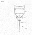
- Fig. 2 shows an embodiment of seed adhesion (a particle adhesion step) by the flow-down method.
- a base material 1 is secured to a lower end of a wide-mouth funnel 2, and a valve 3 is opened to pour a slurry 4 through an upper part of the base material 1, so that the slurry can pass through cells.
- the particle adhesion step can thus be performed.
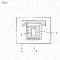
- Fig. 3 shows an embodiment of a film formation step of immersing the base material 1 into a sol 7 and carrying out hydrothermal synthesis to form the zeolite film on the base material 1.
- the base material 1 is placed into a heat resistant container 5, and the sol 7 is placed, to carry out a heating treatment (the hydrothermal synthesis), whereby the zeolite film can be produced.
- the sol 7 (a raw material solution) contains a structure-directing agent (e.g., 1-adamantane amine), silica (SiO 2 ), water, and the like.
- a content ratio between 1-adamantane amine and SiO 2 (1-adamantane amine/SiO 2 ) is preferably from 0.002 to 0.5 by molar ratio
- a content ratio between water and SiO 2 is preferably from 10 to 500 by molar ratio.
- a concentration of a solid content in the slurry 4 is preferably in a range of 0.00001 to 1 mass%, more preferably in a range of 0.0001 to 0.5 mass%, and further preferably in a range of 0.0005 to 0.2 mass%.
- concentration is lower than a lower limit value of the concentration range, the number of steps increases, which causes high cost.
- concentration exceeds 1 mass%, a thick zeolite particle layer is formed on the surface of the base material. The thick film causes a low flux.
- water can be used as a solvent to disperse zeolite particles.
- an organic solvent or an aqueous solution of the organic solvent can be used.
- ethanol, an aqueous ethanol solution or the like can be used.
- the solvent is ethanol having a high volatility
- immediately after the liquid flows down the interior of the base material is pressurized by volatilized ethanol. Therefore, the liquid which has flowed down is pushed out to the surface of the base material, and an amount of the infiltration of the slurry for seed adhesion can further be decreased.
- the masking of an outer peripheral portion 1a of the base material 1 with a seal tape is performed and the seed sol using ethanol as the solvent is also used, the amount of the infiltration of the slurry 4 for seed adhesion can further be decreased.
- a step of allowing the slurry 4 containing the zeolite particles which become the seeds to flow down is preferably performed a plurality of times.
- the plurality of times is from about twice to ten times. With the number of the times exceeding this range, an amount of operation is large, and much cost is required.
- the number of the times is preferably about eight times at maximum, and more preferably from about twice to six times.
- the process for producing the zeolite film of the present invention preferably includes a step of allowing the slurry 4 containing the zeolite particles which become the seeds to flow down, vertically inverting the base material 1, and then allowing the slurry 4 containing the zeolite particles to flow down.
- the zeolite particles can evenly adhere to the whole surface of the base material 1.
- the outer peripheral portion 1a of the base material 1 is preferably masked with the seal tape or the like.
- the masking is performed, the amount of the infiltration of the slurry 4 for seed adhesion can be decreased, and the zeolite particles can more evenly adhere.
- the amount of the infiltration of the slurry 4 for seed adhesion is decreased, it is possible to form a thinner zeolite film.
- the process for producing the zeolite film of the present invention preferably includes a forced-air drying step after allowing the slurry 4 containing the zeolite particles which become the seeds to flow down.
- the forced-air drying is to circulate air through the surface of the base material 1 to which the slurry 4 containing the zeolite particles adhere, thereby drying the slurry 4.
- a drying speed rises. With the movement of a liquid when the liquid evaporates, the zeolite particles can move to easily gather on the surface.
- the forced-air drying is preferably performed with humidified air.
- the seeds can more strongly be secured onto the base material 1.
- the detachment of the zeolite particles during the subsequent hydrothermal synthesis can be prevented. It is possible to stably prepare the zeolite film having fewer defects.
- the process includes an exposure step of exposing, into steam, the base material 1 subjected to the forced-air drying with air which is not humidified after the forced-air drying, after allowing the slurry 4 to flow down so that the seeds adhere. Also in this case, a similar effect can be obtained.
- the process for producing the zeolite film of the present invention can be applied to zeolites having crystal structures such as LTA, MFI, MOR, FER, FAU and DDR.
- zeolites having crystal structures such as LTA, MFI, MOR, FER, FAU and DDR.
- the zeolite particles are made of a DDR type zeolite.
- the embodiment of the process for producing the zeolite film in the case of the DDR type zeolite will specifically be described with reference to Fig. 1 .
- DDR type zeolite crystal powder is produced. This powder is used as it is. If necessary, the powder is ground, and used as seed crystals.
- the DDR type zeolite powder (this becomes the seed crystals) is dispersed in the solvent to prepare the slurry 4 (the slurry liquid for seed adhesion).
- the slurry liquid for seed adhesion is preferably diluted with the solvent so that the concentration of the solid content included in this liquid is 1 mass% or lower.
- the solvent for the diluting is water or ethanol, or is preferably the aqueous ethanol solution.
- an organic solvent such as acetone or IPA or an aqueous solution of the organic solvent can be used, in addition to the water or ethanol.
- a drying time can be shortened.
- the amount of the infiltration of the slurry 4 for seed adhesion can be decreased. Therefore, it is possible to form a thinner zeolite film.
- a usual stirring method may be employed, but a method such as an ultrasonic treatment may be employed.
- a particle adhesion step of allowing the slurry 4, where the zeolite particles which become the seeds are dispersed, to flow down by the self-weight of the slurry, so that the zeolite particles adhere to the base material 1 (S1 of Fig. 1 ).
- the base material 1 which becomes a support a nonporous material or a porous material can be used.
- the support it is possible to suitably use the nonporous or porous material made of a ceramic such as alumina, zirconia or mullite, glass, zeolite, clay, metal, carbon, an organic polymer (e.g., a fluorine resin) or the like.
- the base material 1 having a honeycomb shape holes (cells) are made like holes in a lotus root
- the base material 1 is secured to the lower end of the wide-mouth funnel 2, and the slurry 4 for seed adhesion is poured through the upper part of the base material 1 to pass through the cells, whereby the seeds can adhere.
- the slurry flows down, the outer peripheral portion 1a of the base material 1 is masked with the seal tape or the like. In consequence, the amount of the infiltration of the slurry 4 for seed adhesion can further be small and even.
- the base material 1 through which the slurry 4 has flowed down is subjected to the forced-air drying at room temperature to 120°C with an air velocity of 1 to 10 m/s for 30 to 60 minutes (S2 of Fig. 1 ). Then, the slurry 4 for seed adhesion is again allowed to flow down through the base material 1.
- the flow-down of the slurry 4 for seed adhesion and the forced-air drying are repeated twice to six times, the seeds can evenly adhere to the surface of the base material 1.
- the forced-air drying can be performed in a shorter period of drying time.
- the base material 1 to which the seeds adhere is subjected to the forced-air drying with the humidified air, or the steam exposure after the forced-air drying, whereby the seeds can more strongly be secured onto the base material 1.
- the forced-air drying is performed with the humidified air
- the drying is preferably performed with an absolute humidity of 10 g/m 3 or higher.
- the exposure to the steam the exposure is preferably performed in an environment with an absolute humidity of 25 g/m 3 or higher for ten minutes or longer. With the absolute humidity of 25 g/m 3 , the detachment of the zeolite particles during the subsequent hydrothermal synthesis can be prevented, and the zeolite film having fewer defects can stably be prepared.
- the detached zeolite particles are deposited on a bottom part of the hydrothermal synthesis container, a jig and the like, which causes damage to the jig sometimes. Therefore, an amount of the zeolite particles to be detached is preferably as small as possible.
- 1-adamantane amine is a structure-directing agent (SDA) in the synthesis of the DDR type zeolite, i.e., a substance which becomes a casting mold to form a crystal structure of the DDR type zeolite, and hence a molar ratio thereof to silica (SiO 2 ) which is a raw material of the DDR type zeolite is important.
- SDA structure-directing agent
- the 1-adamantane amine/SiO 2 molar ratio needs to be in a range of 0.002 to 0.5, is preferably in a range of 0.002 to 0.2, and is further preferably in a range of 0.002 to 0.03.
- 1-adamantane amine is hardly soluble in the water which is the solvent of the hydrothermal synthesis. Therefore, the substance is dissolved in ethylenediamine, and then used in the preparation of the raw material solution.
- 1-adamantane amine is completely dissolved in ethylenediamine to prepare the raw material solution having an even state, it is possible to form the DDR type zeolite having an even crystal size.
- a molar ratio of ethylenediamine/1-adamantane amine needs to be in a range of 4 to 35, is preferably in a range of 8 to 24, and is further preferably in a range of 10 to 20.
- ethylenediamine/1-adamantane amine molar ratio is smaller than this range, an amount of ethylenediamine is not sufficient for completely dissolving 1-adamantane amine. On the other hand, if the ratio exceeds this range, ethylenediamine is used more than necessary, which is unfavorable from the aspect of the producing cost.
- colloidal silica is used as a silica source.
- colloidal silica commercially available colloidal silica can suitably be used.
- colloidal silica can be prepared by dissolving fine powder silica in water or hydrolyzing alkoxide.
- a molar ratio between water and silica (SiO 2 ) contained in the raw material solution needs to be in a range of 10 to 500, is preferably in a range of 14 to 250, and is further preferably in a range of 14 to 112. If the water/SiO 2 molar ratio is smaller than this range, a concentration of SiO 2 in the raw material solution is excessively high, which is not preferable in that a large amount of non-crystallized non-reacted SiO 2 remains. If the ratio exceeds this range, the concentration of SiO 2 in the raw material solution is excessively low, which is not preferable in that the DDR type zeolite cannot be formed.
- the low-silica DDR type zeolite a DDR type zeolite containing aluminum and metal cations in a framework thereof (hereinafter referred to as "the low-silica DDR type zeolite"), in addition to an all-silica DDR type zeolite.
- This low-silica DDR type zeolite includes cations in pores, and is different from the all-silica DDR type zeolite in adsorption performance and catalyst performance.
- an aluminum source and a cation source are added to prepare the raw material solution.
- an SiO 2 /Al 2 O 3 molar ratio needs to be in a range of 50 to 1000, is preferably in a range of 70 to 300, and is further preferably in a range of 90 to 200. If the SiO 2 /Al 2 O 3 molar ratio is smaller than this range, a ratio of amorphous SiO 2 other than the DDR type zeolite unfavorably becomes large. On the other hand, if the ratio exceeds this range, the DDR type zeolite can be produced. However, the amounts of aluminum and cations become remarkably small, and hence the low-silica DDR type zeolite cannot exert its properties, and unfavorably is not different from the all-silica zeolite at all.
- Examples of the cations include cations of an alkali metal such as K, Na, Li, Rb or Cs.
- examples of the cation source include sodium hydroxide and sodium aluminate.
- an X 2 O/Al 2 O 3 molar ratio needs to be in a range of 1 to 25, is preferably in a range of 3 to 20, and is further preferably in a range of 6 to 15. If the X 2 O/Al 2 O 3 molar ratio is smaller than this range, the DDR type zeolite having a desired SiO 2 /Al 2 O 3 molar ratio unfavorably is not easily obtained. On the other hand, if the ratio exceeds this range, amorphous SiO 2 is unfavorably mixed into a product.
- examples of an especially preferable configuration include a method in which a solution obtained by dissolving 1-adamantane amine in ethylenediamine, water as the solvent and colloidal silica (further aluminum sulfate as the aluminum source and sodium hydroxide as the cation source, when low-silica type DDR is synthesized) are mixed at a predetermined ratio, and dissolved to prepare the raw material solution.
- colloidal silica further aluminum sulfate as the aluminum source and sodium hydroxide as the cation source, when low-silica type DDR is synthesized
- a container into which the raw material solution is placed (e.g., a wide-mouth jar) is set in a homogenizer, followed by stirring, to prepare the sol 7 for use in the hydrothermal synthesis.
- the base material 1 to which the seeds adhere by the flow-down method is placed into the heat resistant container 5.
- the container is placed into a drier 8, to carry out a heating treatment (the hydrothermal synthesis) at 110 to 200°C for 16 to 120 hours, thereby producing a zeolite film (S3 of Fig. 1 ).
- a temperature of the heating treatment (the synthesis temperature) is preferably in a range of 110 to 200°C, further preferably in a range of 120 to 180°C, and especially preferably in a range of 120 to 170°C. If the temperature of the heating treatment is lower than this range, the DDR type zeolite unfavorably cannot be formed. On the other hand, if the temperature exceeds this range, a DOH type zeolite which is not desired is unfavorably formed owing to phase transition.
- the time of the heating treatment (the synthesis time) in the producing process of the present invention, a remarkably short time of several hours to five days is sufficient.
- the DDR type zeolite powder is added to the base material by the flow-down method, and hence the crystallization of the DDR type zeolite is promoted.
- the raw material solution (the sol 7) during the heating treatment. Since 1-adamantane amine to be contained in the raw material solution is dissolved in ethylenediamine, the raw material solution is held in an even state. It is to be noted that in a conventional process, if the raw material solution is not stirred, mixed crystals of DDR and DOH are formed sometimes. However, according to the producing process of the present invention, even if the raw material solution is not constantly stirred, any DOH is not formed, and single-phase crystals of DDR can be formed.
- the base material 1 provided with the zeolite film is water-washed, or boil-cleaned at 80 to 100°C (S4 of Fig. 1 ).
- the base material is removed, and dried at 80 to 100°C (S5 of Fig. 1 ).
- the base material 1 is placed into an electric furnace, and heated in the atmosphere at 400 to 800°C for one to 200 hours, to burn and remove 1-adamantane amine in the pores of the zeolite film (S6 of Fig. 1 ).
- DDR type zeolite crystal powder was produced. This powder was used as it is. If necessary, the powder was ground and used as seed crystals. The synthesized or ground seed crystals were dispersed in water, and coarse particles were removed therefrom, to prepare a seed crystal dispersion liquid.
- the seed crystal dispersion liquid prepared in (1) was diluted with ion exchange water or ethanol, adjusted so that a DDR concentration was from 0.001 to 0.36 mass% (a solid content concentration in a slurry 4), and stirred at 300 rpm by a stirrer, thereby obtaining a slurry liquid for seed adhesion (the slurry 4).
- a porous base material 1 (provided with holes like holes in a lotus root, having a diameter of 30 mm and a length of 160 mm, and including glass seals at both ends) was secured to the lower end of a wide-mouth funnel 2, and 160 ml of slurry liquid for seed adhesion was poured through an upper part of the base material 1 to pass through cells (see Fig. 2 ).
- an outer peripheral portion 1a of the material was masked with a teflon tape, and then seeds adhered thereto (Examples 9 to 26).
- the interior of each cell was subjected to forced-air drying on conditions of room temperature or 80°C and an air velocity of 3 to 6 m/s for 10 to 30 min.
- the flow-down of the slurry 4 and the forced-air drying were repeated once to six times to obtain samples.
- air was not humidified during the forced-air drying (an absolute humidity of the air: 3 g/m 3 ).
- Example 16 air was humidified during the forced-air drying, and the absolute humidity of the air for use in the forced-air drying was 12 g/m 3 .
- a steam exposure step was performed to expose the base material 1 subjected to the forced-air drying and provided with seeds in an environment with an absolute humidity of 23 to 36 g/m 3 for 30 minutes to 50 hours, to perform a steam exposure treatment. After drying, the observation of a fine structure was performed with an electron microscope. It has been confirmed that DDR particles adhere to the surface of the base material 1 on the conditions of the examples.
- the wide-mouth jar into which the raw material solution was placed was set in a homogenizer, and stirred for one hour.
- a stainless steel heat resistant container 5 provided with an inner cylinder having an inner volume of 300 ml and made of a fluorine resin
- the base material 1 to which DDR particles adhered in (2) was disposed.
- a prepared raw material solution (a sol 7) was placed into the container, and a heating treatment (hydrothermal synthesis) was carried out at 120 to 170°C for 16 to 84 hr. (see Fig. 3 ).
- a heating treatment hydrogen synthesis
- the film was formed, cleaning and drying (80°C) were performed, and then an amount of He permeation was measured. It has been confirmed that on conditions of the examples, the amount of He permeation became a measurement limit or smaller ( ⁇ 0.018 L/min•m 2 •kPa) and the whole surface could be covered.
- the film which could be covered was heated with an electric furnace in the atmosphere at 450 or 500°C for 50 hours, to burn and remove 1-adamantane amine in pores. Through X-ray diffraction, a crystal phase was identified, and a DDR type zeolite was confirmed. Afterward, a fine structure was observed with the electron microscope.
- the crystal phase of the obtained film was checked through the X-ray diffraction, to evaluate the crystal phase. Then, only diffraction peaks of the DDR type zeolite and alumina which was the base material 1 were detected. It is to be noted that "the diffraction peak of the DDR type zeolite" in the X-ray diffraction is a diffraction peak disclosed in No. 38-651 or 41-571 corresponding to decal-dodecasil 3R described in International Center for Diffraction Data (ICDD) "Powder Diffraction File".
- ICDD International Center for Diffraction Data
- Example 2 The same seed crystals as those used in Example 1 were dispersed in a sol 7 similar to that prepared in Example 1, and hydrothermal synthesis was carried out at 135°C for 48 hours, to form a film. In the same manner as in the examples, the measurement of an amount of He permeation and the observation of a fine structure with a scanning electron microscope were performed.
- Table 1 to Table 3 The results of the above-mentioned examples and comparative examples are shown in Table 1 to Table 3. It is to be noted that Table 2 distinctively shows Examples 15 and 16 where air is not humidified in a forced-air drying step, and Table 3 distinctively shows Examples 17 to 26 where the forced-air drying step is performed with air which is not humidified, and then steam exposure is not performed.
- a glass interface was covered, and it was possible to form a thin zeolite film (the DDR film) having a thickness of 2 to 8 ⁇ m.
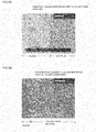
- Fig. 4A is a photograph of a cutout section of Example 1 after film formation by a scanning electron microscope. It is seen that the DDR film is thinly formed.
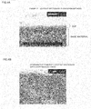
- Fig. 5A is a photograph of a glass interface part of Example 1 after the film formation by the scanning electron microscope. It is seen that the whole surface of the base material 1 is covered with the DDR film and that the glass interface part can be covered.
- Fig. 5B is a photograph of a glass interface part of Comparative Example 1 after film formation by the scanning electron microscope. It is seen that the base material 1 is exposed and the glass interface part is not covered with the DDR film. Further in Comparative Example 1, the glass interface part is not covered with any film, and hence an amount of He permeation could not be measured.
- Fig. 4B is a photograph of a cutout section of Comparative Example 2 after film formation by the scanning electron microscope. All the region of the photograph indicates a mixed layer of a base material 1 and a DDR film, and the DDR film has a film thickness of 20 ⁇ m or larger. It is seen that the DDR film is thickly formed as compared with Example 1. In consequence, it was possible to confirm that the DDR films prepared in the examples had a sufficiently small film thickness as compared with the film prepared in Comparative Example 2.
- Example 8 As seen from comparison between Example 8 and Example 9, when a slurry 4 containing zeolite particles which become seeds is allowed to flow down, an outer peripheral portion 1a of a base material 1 is masked with a seal tape or the like, whereby an amount of the infiltration of the slurry 4 for seed adhesion can further be even. As a consequence, it was possible to prepare a zeolite film having less fluctuations in film thickness.
- Example 9 when a solvent of a slurry 4 for seed adhesion is changed from water to ethanol having a high volatility, an amount of the infiltration of the slurry 4 for seed adhesion can be decreased. As a consequence, it was possible to prepare a zeolite film having a smaller film thickness. Moreover, when the ethanol solvent and masking are used together, the amount of the infiltration of the slurry 4 for seed adhesion can further be even. As a consequence, it was possible to prepare a zeolite film having less fluctuations in film thickness.
- Example 15 and 17 to 20 a deposited matter due to the drop-out of the zeolite particles were present during the film formation, but in Examples 16 and 21 to 26, any deposited matter was not present.
- the forced-air drying of the base material 1 was performed with air having an absolute humidity of 12 g/m 3 or higher after the seed adhesion, or the base material 1 subjected to the forced-air drying after the seed adhesion was exposed into steam having an absolute humidity of 27 g/m 3 or higher, it was possible to prevent the detachment of the zeolite particles during the film formation.
- the present invention can be utilized as a process for producing a zeolite film for use in a gas separation film, a pervaporation film and the like.
Landscapes
- Chemical & Material Sciences (AREA)
- Chemical Kinetics & Catalysis (AREA)
- Geology (AREA)
- Inorganic Chemistry (AREA)
- Engineering & Computer Science (AREA)
- Life Sciences & Earth Sciences (AREA)
- General Life Sciences & Earth Sciences (AREA)
- Organic Chemistry (AREA)
- Materials Engineering (AREA)
- Manufacturing & Machinery (AREA)
- Oil, Petroleum & Natural Gas (AREA)
- Crystallography & Structural Chemistry (AREA)
- General Chemical & Material Sciences (AREA)
- Analytical Chemistry (AREA)
- Silicates, Zeolites, And Molecular Sieves (AREA)
- Separation Using Semi-Permeable Membranes (AREA)
Abstract
Description
- The present invention relates to a process for producing a zeolite film, and a zeolite film obtained by the producing process.
- There are present a large number of kinds (types) of zeolites having different crystal structures, for example, LTA, MFI, MOR, FER, FAU and DDR. It is known that, for example, the deca-dodecasil 3R (DDR) type zeolite is formed by a polyhedron containing a main component of silica and including pores made of eight-membered ring oxygen and having pore diameters of 4.4x3.6 angstroms. Since the DDR type zeolite has such small pore diameters, it is possible to selectively adsorb comparatively small molecules of carbon dioxide (CO2), methane (CH4) and ethane (C2H6), so that use applications of the zeolite are expected to be a gas separation film which can selectively separate these molecules, an adsorber, and the like.
- There is known a method in which a raw material solution, where zeolite powder which becomes seed crystals, is dispersed, and an appropriate support material for forming a film are placed into a container or the like to carry out hydrothermal synthesis (Patent Document 1). Moreover, as a method of loading seed crystals onto the surface of a support and carrying out hydrothermal synthesis to produce a zeolite film which does not have any defect and which has an even thickness, there is known a method of filtering a slurry containing the seed crystals through a porous support (
Patent Documents 2 and 3). -
- Patent Document 1:
JP-A-2003-159518 - Patent Document 2:
JP-A-2001-97715 - Patent Document 3:
JP-A-2008-74695 - However, according to a conventional process for producing a zeolite film, it has been difficult to form an evenly thin film. According to a seed dispersion method of
Patent Document 1, a liquid obtained by dispersing seeds in an aqueous solution is used. Therefore, a base material is penetrated by seeds, and the seeds adhere to the interior of the base material and then adhere to the surface of the base material. In consequence, seed crystals are thickly formed in the base material, which lowers a flux (a permeation speed becomes low). - According to the filtering method of
Patent Documents - A theme of the present invention lies in that there are provided a process for producing a zeolite film in which seed crystals thinly adhere to the surface of a support to form a thin and even zeolite film having fewer defects than conventional zeolite films, and a zeolite film obtained by the producing process.
- The present inventors have found that when a slurry, where zeolite particles which become seeds are dispersed, is allowed to flow down by the self-weight of the slurry, the zeolite particles adhere to a base material, and the above theme can be solved. According to the present invention, there are provided the following process for producing a zeolite film, and a zeolite film obtained by the producing process.
- [1] A process for producing a zeolite film comprising: a particle adhesion step of allowing a slurry, where zeolite particles which become seeds are dispersed, to flow down on the surface of a base material by the self-weight of the slurry, so that the zeolite particles adhere to the base material; and a film formation step of immersing the base material, to which the zeolite particles adhere, into a sol to carry out hydrothermal synthesis, thereby forming the zeolite film on the base material.
- [2] The process for producing the zeolite film according to the above [1], wherein the zeolite particles are made of a DDR type zeolite.
- [3] The process for producing the zeolite film according to the above [2], wherein in the film formation step, the sol has a content ratio between 1-adamantane amine and SiO2 (1-adamantane amine/SiO2 in a range of 0.002 to 0.5 by molar ratio, and has a content ratio between water and SiO2 (water/SiO2) in a range of 10 to 500 by molar ratio.
- [4] The process for producing the zeolite film according to any one of the above [1] to [3], wherein in the particle adhesion step, a solvent to disperse the zeolite particles is water.
- [5] The process for producing the zeolite film according to any one of the above [1] to [3], wherein in the particle adhesion step, a solvent to disperse the zeolite particles is an organic solvent or an aqueous solution of the organic solvent.
- [6] The process for producing the zeolite film according to any one of the above [1] to [3], wherein in the particle adhesion step, a solvent to disperse the zeolite particles is ethanol or an aqueous ethanol solution.
- [7] The process for producing the zeolite film according to any one of the above [1] to [6], wherein in the particle adhesion step, a concentration of a solid content in the slurry is 1 mass% or lower.
- [8] The process for producing the zeolite film according to any one of the above [1] to [7], wherein in the particle adhesion step, the slurry is allowed to flow down after a masking treatment of the surface of the base material excluding the surface thereof to which the zeolite particles adhere.
- [9] The process for producing the zeolite film according to any one of the above [1] to [8], wherein in the particle adhesion step, a step of allowing the slurry containing the zeolite particles which become the seeds to flow down is performed a plurality of times.
- [10] The process for producing the zeolite film according to the above [9], wherein the particle adhesion step includes a step of allowing the slurry containing the zeolite particles which become the seeds to flow down, vertically inverting the base material, and then allowing the slurry containing the zeolite particles to flow down.
- [11] The process for producing the zeolite film according to any one of the above [1] to [10], further comprising: a forced-air drying step after allowing the slurry containing the zeolite particles which become the seeds to flow down.
- [12] The process for producing the zeolite film according to the above [11], wherein the forced-air drying step is performed in humidified air.
- [13] The process for producing the zeolite film according to any one of the above [1] to [12], further comprising a step of exposure to steam, after allowing the slurry containing the zeolite particles which become the seeds to flow down and performing forced-air drying.
- [14] A zeolite film obtained by the process for producing the zeolite film according to any one of the above [1] to [13] and having a film thickness of 10 µm or smaller.
- The present invention is a process of allowing a slurry to flow down on the surface of a base material by the self-weight of the slurry so as to come in contact with the base material, thereby adhering zeolite particles (seed particles) to the base material. An equipment such as a pump or a vacuum chamber for use in a filtering method is not required, and hence the equipment can be simplified. Moreover, seeds can adhere even to a portion where a differential pressure is not easily generated or the seeds cannot easily adhere by the filtering method (e.g., a glass seal interface around an end surface of the base material, or the like). The seeds do not penetrate the interior of the base material, but can adhere only to the surface thereof. Therefore, a thickness of the portion to be provided with the seed particles can be decreased, and eventually, it is possible to form a dense zeolite film having a small film thickness. A sufficient permeation speed can be obtained.
-
-
Fig. 1 is a flowchart for explaining a process for producing a zeolite film by a flow-down method; -
Fig. 2 is an exemplary diagram for explaining seed adhesion by the flow-down method; -
Fig. 3 is an exemplary diagram for explaining hydrothermal synthesis; -
Fig. 4A is a photograph of a cutout section of Example 1 by a scanning electron microscope; -
Fig. 4B is a photograph of a cutout section of Comparative Example 2 by the scanning electron microscope; -
Fig. 5A is a photograph of a glass interface part of Example 1 by the scanning electron microscope; and -
Fig. 5B is a photograph of a glass interface part of Comparative Example 1 by the scanning electron microscope. - Hereinafter, embodiments of the present invention will be described with reference to the drawings. The present invention is not limited to the following embodiments, and changes, modifications and improvements can be added thereto without departing from the scope of the invention.
- A process for producing a zeolite film of the present invention includes a particle adhesion step of allowing a slurry, where zeolite particles which become seeds are dispersed, to flow down on the surface of a base material by the self-weight of the slurry, so that the zeolite particles adhere to the base material; and a film formation step of immersing the base material, to which the zeolite particles adhere, into a sol to carry out hydrothermal synthesis, thereby forming the zeolite film on the base material. The flow-down in the particle adhesion step indicates that the slurry is allowed to freely fall down on the base material by the self-weight of the slurry, and the slurry flows on the surface of the substrate. In the flow-down method, for example, the slurry is poured into cylindrical holes made in the base material, whereby a large amount of liquid flows in parallel with a plane. In this case, the slurry which has flowed down flows on the surface of the base material by the self-weight thereof. In consequence, the slurry infiltrates less into the base material. On the other hand, a heretofore known drop-down method is, for example, a method of dropping a small amount of slurry down vertically from a flat plate, and the dropped slurry infiltrates into the flat plate by the self-weight thereof. In consequence, a film thickness increases.
-
Fig. 2 shows an embodiment of seed adhesion (a particle adhesion step) by the flow-down method. Abase material 1 is secured to a lower end of a wide-mouth funnel 2, and avalve 3 is opened to pour aslurry 4 through an upper part of thebase material 1, so that the slurry can pass through cells. The particle adhesion step can thus be performed. Moreover,Fig. 3 shows an embodiment of a film formation step of immersing thebase material 1 into asol 7 and carrying out hydrothermal synthesis to form the zeolite film on thebase material 1. Thebase material 1 is placed into a heatresistant container 5, and thesol 7 is placed, to carry out a heating treatment (the hydrothermal synthesis), whereby the zeolite film can be produced. It is to be noted that the sol 7 (a raw material solution) contains a structure-directing agent (e.g., 1-adamantane amine), silica (SiO2), water, and the like. As described later, a content ratio between 1-adamantane amine and SiO2 (1-adamantane amine/SiO2) is preferably from 0.002 to 0.5 by molar ratio, and a content ratio between water and SiO2 (water/SiO2) is preferably from 10 to 500 by molar ratio. - In the seed adhesion (the particle adhesion step), a concentration of a solid content in the
slurry 4 is preferably in a range of 0.00001 to 1 mass%, more preferably in a range of 0.0001 to 0.5 mass%, and further preferably in a range of 0.0005 to 0.2 mass%. When the concentration is lower than a lower limit value of the concentration range, the number of steps increases, which causes high cost. Moreover, if the concentration exceeds 1 mass%, a thick zeolite particle layer is formed on the surface of the base material. The thick film causes a low flux. - For the
slurry 4 of the particle adhesion step, water can be used as a solvent to disperse zeolite particles. Moreover, an organic solvent or an aqueous solution of the organic solvent can be used. Furthermore, ethanol, an aqueous ethanol solution or the like can be used. Especially in a case where the solvent is ethanol having a high volatility, immediately after the liquid flows down, the interior of the base material is pressurized by volatilized ethanol. Therefore, the liquid which has flowed down is pushed out to the surface of the base material, and an amount of the infiltration of the slurry for seed adhesion can further be decreased. Furthermore, when the masking of an outerperipheral portion 1a of thebase material 1 with a seal tape is performed and the seed sol using ethanol as the solvent is also used, the amount of the infiltration of theslurry 4 for seed adhesion can further be decreased. - In the particle adhesion step, a step of allowing the
slurry 4 containing the zeolite particles which become the seeds to flow down (Fig. 2 ) is preferably performed a plurality of times. The plurality of times is from about twice to ten times. With the number of the times exceeding this range, an amount of operation is large, and much cost is required. The number of the times is preferably about eight times at maximum, and more preferably from about twice to six times. When the step is performed the plurality of times, the zeolite particles can evenly adhere to the whole surface of thebase material 1. - The process for producing the zeolite film of the present invention preferably includes a step of allowing the
slurry 4 containing the zeolite particles which become the seeds to flow down, vertically inverting thebase material 1, and then allowing theslurry 4 containing the zeolite particles to flow down. In this case, the zeolite particles can evenly adhere to the whole surface of thebase material 1. - Moreover, when the
slurry 4 containing the zeolite particles which become the seeds is allowed to flow down, the outerperipheral portion 1a of thebase material 1 is preferably masked with the seal tape or the like. When the masking is performed, the amount of the infiltration of theslurry 4 for seed adhesion can be decreased, and the zeolite particles can more evenly adhere. When the amount of the infiltration of theslurry 4 for seed adhesion is decreased, it is possible to form a thinner zeolite film. - The process for producing the zeolite film of the present invention preferably includes a forced-air drying step after allowing the
slurry 4 containing the zeolite particles which become the seeds to flow down. The forced-air drying is to circulate air through the surface of thebase material 1 to which theslurry 4 containing the zeolite particles adhere, thereby drying theslurry 4. When the forced-air drying is performed, a drying speed rises. With the movement of a liquid when the liquid evaporates, the zeolite particles can move to easily gather on the surface. - Moreover, the forced-air drying is preferably performed with humidified air. When the forced-air drying is performed with the humidified air, the seeds can more strongly be secured onto the
base material 1. When the seeds are strongly secured onto thebase material 1, the detachment of the zeolite particles during the subsequent hydrothermal synthesis can be prevented. It is possible to stably prepare the zeolite film having fewer defects. It is to be noted that the process includes an exposure step of exposing, into steam, thebase material 1 subjected to the forced-air drying with air which is not humidified after the forced-air drying, after allowing theslurry 4 to flow down so that the seeds adhere. Also in this case, a similar effect can be obtained. - The process for producing the zeolite film of the present invention can be applied to zeolites having crystal structures such as LTA, MFI, MOR, FER, FAU and DDR. In the present description, there will be described an example where the zeolite particles are made of a DDR type zeolite. Hereinafter, the embodiment of the process for producing the zeolite film in the case of the DDR type zeolite will specifically be described with reference to
Fig. 1 . - DDR type zeolite crystal powder is produced. This powder is used as it is. If necessary, the powder is ground, and used as seed crystals. The DDR type zeolite powder (this becomes the seed crystals) is dispersed in the solvent to prepare the slurry 4 (the slurry liquid for seed adhesion). The slurry liquid for seed adhesion is preferably diluted with the solvent so that the concentration of the solid content included in this liquid is 1 mass% or lower. The solvent for the diluting is water or ethanol, or is preferably the aqueous ethanol solution. As the solvent for use in the diluting, an organic solvent such as acetone or IPA or an aqueous solution of the organic solvent can be used, in addition to the water or ethanol. When the organic solvent having a high volatility is used, a drying time can be shortened. Moreover, the amount of the infiltration of the
slurry 4 for seed adhesion can be decreased. Therefore, it is possible to form a thinner zeolite film. As a method of dispersing the DDR type zeolite powder in the slurry liquid, a usual stirring method may be employed, but a method such as an ultrasonic treatment may be employed. - Next, there is performed a particle adhesion step of allowing the
slurry 4, where the zeolite particles which become the seeds are dispersed, to flow down by the self-weight of the slurry, so that the zeolite particles adhere to the base material 1 (S1 ofFig. 1 ). As thebase material 1 which becomes a support, a nonporous material or a porous material can be used. As the support, it is possible to suitably use the nonporous or porous material made of a ceramic such as alumina, zirconia or mullite, glass, zeolite, clay, metal, carbon, an organic polymer (e.g., a fluorine resin) or the like. - When the
porous base material 1 having a honeycomb shape (holes (cells) are made like holes in a lotus root) is used, as shown inFig. 2 , thebase material 1 is secured to the lower end of the wide-mouth funnel 2, and theslurry 4 for seed adhesion is poured through the upper part of thebase material 1 to pass through the cells, whereby the seeds can adhere. It is to be noted that when the slurry flows down, the outerperipheral portion 1a of thebase material 1 is masked with the seal tape or the like. In consequence, the amount of the infiltration of theslurry 4 for seed adhesion can further be small and even. - Next, the
base material 1 through which theslurry 4 has flowed down is subjected to the forced-air drying at room temperature to 120°C with an air velocity of 1 to 10 m/s for 30 to 60 minutes (S2 ofFig. 1 ). Then, theslurry 4 for seed adhesion is again allowed to flow down through thebase material 1. When the flow-down of theslurry 4 for seed adhesion and the forced-air drying are repeated twice to six times, the seeds can evenly adhere to the surface of thebase material 1. When ethanol or a volatile solvent or an aqueous solution thereof is used as the solvent of the slurry, the forced-air drying can be performed in a shorter period of drying time. - The
base material 1 to which the seeds adhere is subjected to the forced-air drying with the humidified air, or the steam exposure after the forced-air drying, whereby the seeds can more strongly be secured onto thebase material 1. When the forced-air drying is performed with the humidified air, the drying is preferably performed with an absolute humidity of 10 g/m3 or higher. In the case of the exposure to the steam, the exposure is preferably performed in an environment with an absolute humidity of 25 g/m3 or higher for ten minutes or longer. With the absolute humidity of 25 g/m3, the detachment of the zeolite particles during the subsequent hydrothermal synthesis can be prevented, and the zeolite film having fewer defects can stably be prepared. The detached zeolite particles are deposited on a bottom part of the hydrothermal synthesis container, a jig and the like, which causes damage to the jig sometimes. Therefore, an amount of the zeolite particles to be detached is preferably as small as possible. - Next, there is prepared a raw material solution having a predetermined composition containing 1-adamantane amine dissolved in ethylenediamine.
- 1-adamantane amine is a structure-directing agent (SDA) in the synthesis of the DDR type zeolite, i.e., a substance which becomes a casting mold to form a crystal structure of the DDR type zeolite, and hence a molar ratio thereof to silica (SiO2) which is a raw material of the DDR type zeolite is important. The 1-adamantane amine/SiO2 molar ratio needs to be in a range of 0.002 to 0.5, is preferably in a range of 0.002 to 0.2, and is further preferably in a range of 0.002 to 0.03. If the 1-adamantane amine/SiO2 molar ratio is smaller than this range, 1-adamantane amine of the SDA is running short, and it is difficult to form the DDR type zeolite. On the other hand, if the ratio exceeds this range, expensive 1-adamantane amine is added more than necessary, which is unfavorable from the aspect of producing cost.
- 1-adamantane amine is hardly soluble in the water which is the solvent of the hydrothermal synthesis. Therefore, the substance is dissolved in ethylenediamine, and then used in the preparation of the raw material solution. When 1-adamantane amine is completely dissolved in ethylenediamine to prepare the raw material solution having an even state, it is possible to form the DDR type zeolite having an even crystal size. A molar ratio of ethylenediamine/1-adamantane amine needs to be in a range of 4 to 35, is preferably in a range of 8 to 24, and is further preferably in a range of 10 to 20. If the ethylenediamine/1-adamantane amine molar ratio is smaller than this range, an amount of ethylenediamine is not sufficient for completely dissolving 1-adamantane amine. On the other hand, if the ratio exceeds this range, ethylenediamine is used more than necessary, which is unfavorable from the aspect of the producing cost.
- In the producing process of the present invention, colloidal silica is used as a silica source. As colloidal silica, commercially available colloidal silica can suitably be used. However, colloidal silica can be prepared by dissolving fine powder silica in water or hydrolyzing alkoxide.
- A molar ratio between water and silica (SiO2) contained in the raw material solution (the water/SiO2 molar ratio) needs to be in a range of 10 to 500, is preferably in a range of 14 to 250, and is further preferably in a range of 14 to 112. If the water/SiO2 molar ratio is smaller than this range, a concentration of SiO2 in the raw material solution is excessively high, which is not preferable in that a large amount of non-crystallized non-reacted SiO2 remains. If the ratio exceeds this range, the concentration of SiO2 in the raw material solution is excessively low, which is not preferable in that the DDR type zeolite cannot be formed.
- According to the producing process of the present invention, it is possible to produce a DDR type zeolite containing aluminum and metal cations in a framework thereof (hereinafter referred to as "the low-silica DDR type zeolite"), in addition to an all-silica DDR type zeolite. This low-silica DDR type zeolite includes cations in pores, and is different from the all-silica DDR type zeolite in adsorption performance and catalyst performance. When the low-silica DDR type zeolite is produced, in addition to the water as the solvent and the colloidal silica as the silica source, an aluminum source and a cation source are added to prepare the raw material solution.
- As the aluminum source, aluminum sulfate, sodium aluminate, metal aluminum or the like can be used. In the case of conversion using aluminum oxide, an SiO2/Al2O3 molar ratio needs to be in a range of 50 to 1000, is preferably in a range of 70 to 300, and is further preferably in a range of 90 to 200. If the SiO2/Al2O3 molar ratio is smaller than this range, a ratio of amorphous SiO2 other than the DDR type zeolite unfavorably becomes large. On the other hand, if the ratio exceeds this range, the DDR type zeolite can be produced. However, the amounts of aluminum and cations become remarkably small, and hence the low-silica DDR type zeolite cannot exert its properties, and unfavorably is not different from the all-silica zeolite at all.
- Examples of the cations include cations of an alkali metal such as K, Na, Li, Rb or Cs. In the case of Na, examples of the cation source include sodium hydroxide and sodium aluminate. In the case of conversion using an oxide of the alkali metal, an X2O/Al2O3 molar ratio needs to be in a range of 1 to 25, is preferably in a range of 3 to 20, and is further preferably in a range of 6 to 15. If the X2O/Al2O3 molar ratio is smaller than this range, the DDR type zeolite having a desired SiO2/Al2O3 molar ratio unfavorably is not easily obtained. On the other hand, if the ratio exceeds this range, amorphous SiO2 is unfavorably mixed into a product.
- The preparation of the raw material solution has been described above, but examples of an especially preferable configuration include a method in which a solution obtained by dissolving 1-adamantane amine in ethylenediamine, water as the solvent and colloidal silica (further aluminum sulfate as the aluminum source and sodium hydroxide as the cation source, when low-silica type DDR is synthesized) are mixed at a predetermined ratio, and dissolved to prepare the raw material solution.
- A container into which the raw material solution is placed (e.g., a wide-mouth jar) is set in a homogenizer, followed by stirring, to prepare the
sol 7 for use in the hydrothermal synthesis. Next, as shown inFig. 3 , thebase material 1 to which the seeds adhere by the flow-down method is placed into the heatresistant container 5. Furthermore, after placing theprepared sol 7 into the container, the container is placed into a drier 8, to carry out a heating treatment (the hydrothermal synthesis) at 110 to 200°C for 16 to 120 hours, thereby producing a zeolite film (S3 ofFig. 1 ). - A temperature of the heating treatment (the synthesis temperature) is preferably in a range of 110 to 200°C, further preferably in a range of 120 to 180°C, and especially preferably in a range of 120 to 170°C. If the temperature of the heating treatment is lower than this range, the DDR type zeolite unfavorably cannot be formed. On the other hand, if the temperature exceeds this range, a DOH type zeolite which is not desired is unfavorably formed owing to phase transition.
- As the time of the heating treatment (the synthesis time) in the producing process of the present invention, a remarkably short time of several hours to five days is sufficient. In the producing process of the present invention, the DDR type zeolite powder is added to the base material by the flow-down method, and hence the crystallization of the DDR type zeolite is promoted.
- In the producing process of the present invention, it is not necessary to constantly stir the raw material solution (the sol 7) during the heating treatment. Since 1-adamantane amine to be contained in the raw material solution is dissolved in ethylenediamine, the raw material solution is held in an even state. It is to be noted that in a conventional process, if the raw material solution is not stirred, mixed crystals of DDR and DOH are formed sometimes. However, according to the producing process of the present invention, even if the raw material solution is not constantly stirred, any DOH is not formed, and single-phase crystals of DDR can be formed.
- Next, the
base material 1 provided with the zeolite film is water-washed, or boil-cleaned at 80 to 100°C (S4 ofFig. 1 ). The base material is removed, and dried at 80 to 100°C (S5 ofFig. 1 ). Then, thebase material 1 is placed into an electric furnace, and heated in the atmosphere at 400 to 800°C for one to 200 hours, to burn and remove 1-adamantane amine in the pores of the zeolite film (S6 ofFig. 1 ). As described above, it is possible to form a thin and even zeolite film having fewer defects than conventional films and having a film thickness of 10 µm or smaller. - Hereinafter, the present invention will be described in more detail on the basis of examples, but the present invention is not limited to these examples.
- On the basis of a process for producing a DDR type zeolite as disclosed by M.J. den Exter, J.C. Jansen and H. van Bekkum, Studies in Surface Science and Catalysis vol. 84, Ed. by J. Weitkamp et al., Elsevier (1994) 1159-1166 or
JP-A-2004-083375 - The seed crystal dispersion liquid prepared in (1) was diluted with ion exchange water or ethanol, adjusted so that a DDR concentration was from 0.001 to 0.36 mass% (a solid content concentration in a slurry 4), and stirred at 300 rpm by a stirrer, thereby obtaining a slurry liquid for seed adhesion (the slurry 4). A porous base material 1 (provided with holes like holes in a lotus root, having a diameter of 30 mm and a length of 160 mm, and including glass seals at both ends) was secured to the lower end of a wide-
mouth funnel 2, and 160 ml of slurry liquid for seed adhesion was poured through an upper part of thebase material 1 to pass through cells (seeFig. 2 ). As to thebase materials 1 in part of the examples, an outerperipheral portion 1a of the material was masked with a teflon tape, and then seeds adhered thereto (Examples 9 to 26). As to thebase material 1 through which theslurry 4 flowed down, the interior of each cell was subjected to forced-air drying on conditions of room temperature or 80°C and an air velocity of 3 to 6 m/s for 10 to 30 min. The flow-down of theslurry 4 and the forced-air drying were repeated once to six times to obtain samples. In Example 15, air was not humidified during the forced-air drying (an absolute humidity of the air: 3 g/m3). In Example 16, air was humidified during the forced-air drying, and the absolute humidity of the air for use in the forced-air drying was 12 g/m3. Moreover, in Examples 19 to 26, a steam exposure step was performed to expose thebase material 1 subjected to the forced-air drying and provided with seeds in an environment with an absolute humidity of 23 to 36 g/m3 for 30 minutes to 50 hours, to perform a steam exposure treatment. After drying, the observation of a fine structure was performed with an electron microscope. It has been confirmed that DDR particles adhere to the surface of thebase material 1 on the conditions of the examples. - After placing 7.35 g of ethylenediamine (manufactured by Wako Pure Chemical Industries, Ltd.) into a 100 ml wide-mouth jar made of a fluorine resin, 1.156 g of 1-adamantane amine (manufactured by Aldrich) was added and dissolved so that the precipitation of 1-adamantane amine did not remain. Into another container 98.0 g of 30 mass% of colloidal silica (Snowtex S manufactured by Nissan Chemical Industries, Ltd.) and 116.55 g of ion exchange water were placed, lightly stirred, added to the wide-mouth jar in which ethylenediamine and 1-adamantane amine were mixed, and then strongly shaken, to prepare a raw material solution. Molar ratios of the respective components of the raw material solution were 1-adamantane amine/SiO2 = 0.016 and water/SiO2 = 21. In Examples 13 and 14, adjustment was performed so that molar ratios of components of raw material solutions became 1-adamantane amine/SiO2 = 0.004 and 0.47 and water/SiO2 = 15 and 168, and the raw material solutions were prepared by a similar method. Afterward, the wide-mouth jar into which the raw material solution was placed was set in a homogenizer, and stirred for one hour. In a stainless steel heat
resistant container 5 provided with an inner cylinder having an inner volume of 300 ml and made of a fluorine resin, thebase material 1 to which DDR particles adhered in (2) was disposed. A prepared raw material solution (a sol 7) was placed into the container, and a heating treatment (hydrothermal synthesis) was carried out at 120 to 170°C for 16 to 84 hr. (seeFig. 3 ). When a cutout section of thebase material 1 provided with the film was observed with a scanning electron microscope, a film thickness of the DDR film was 10 µm or smaller. It was possible to confirm that the DDR film prepared in the example had a sufficiently small film thickness as compared with the film prepared in Comparative Example 2 described hereinafter. - To check the presence/absence of defects of the film, the film was formed, cleaning and drying (80°C) were performed, and then an amount of He permeation was measured. It has been confirmed that on conditions of the examples, the amount of He permeation became a measurement limit or smaller (< 0.018 L/min•m2•kPa) and the whole surface could be covered.
- The film which could be covered was heated with an electric furnace in the atmosphere at 450 or 500°C for 50 hours, to burn and remove 1-adamantane amine in pores. Through X-ray diffraction, a crystal phase was identified, and a DDR type zeolite was confirmed. Afterward, a fine structure was observed with the electron microscope.
- The crystal phase of the obtained film was checked through the X-ray diffraction, to evaluate the crystal phase. Then, only diffraction peaks of the DDR type zeolite and alumina which was the
base material 1 were detected. It is to be noted that "the diffraction peak of the DDR type zeolite" in the X-ray diffraction is a diffraction peak disclosed in No. 38-651 or 41-571 corresponding to decal-dodecasil 3R described in International Center for Diffraction Data (ICDD) "Powder Diffraction File". - It was confirmed with the electron microscope that after the seed adhesion, the DDR particles adhered to the surface of the
base material 1. Moreover, it was confirmed that after the film formation, thebase material 1 was covered with DDR. Furthermore, it was possible to confirm from SEM structure of the cutout section that the film had a sufficiently small film thickness as compared with a film prepared by a seed dispersion method. - Seeds adhered to a DDR type zeolite film in accordance with a porous base material provided with a seed crystal containing layer for producing a zeolite film, a zeolite film and a process for producing the zeolite film in
JP-A-2008-74695 sol 7 similar to that prepared in Example 1 at 120°C for 84 hours, to form the film. In the same manner as in the examples, the measurement of an amount of He permeation and the observation of a fine structure with a scanning electron microscope were performed. - The same seed crystals as those used in Example 1 were dispersed in a
sol 7 similar to that prepared in Example 1, and hydrothermal synthesis was carried out at 135°C for 48 hours, to form a film. In the same manner as in the examples, the measurement of an amount of He permeation and the observation of a fine structure with a scanning electron microscope were performed. - The results of the above-mentioned examples and comparative examples are shown in Table 1 to Table 3. It is to be noted that Table 2 distinctively shows Examples 15 and 16 where air is not humidified in a forced-air drying step, and Table 3 distinctively shows Examples 17 to 26 where the forced-air drying step is performed with air which is not humidified, and then steam exposure is not performed.
-
[Table 1] DDR concentration Sol composition (molar ratio) Synthesis temperature Synthesis time Solvent Masking No. of flow-down times Amount of He permeation Film thickness (average) Film thickness (width) Glass interface Mass% 1-adamantane amine/SiO2 Water/SiO2 °C h Present/Absent Times L/min•m2•kPa µm µm - Example 1 0.12 0.016 21 120 84 Water Absent 1 <0.018 2.5 -1 to +3 Covered Example 2 0.360 0.016 21 135 48 Water Absent 3 <0.018 1.5 +4 Covered Example 3 0.06 0.016 21 135 48 Water Absent 1 <0.018 4 ±2 Covered Example 4 0.002 0.016 21 135 48 Water Absent 6 <0.018 5 ±1 Covered Example 5 0.002 0.016 21 150 16 Water Absent 6 <0.018 8 ±1 Covered Example 6 0.001 0.016 21 160 16 Water Absent 2 <0.018 6 ±2 Covered Example 7 0.006 0.016 21 170 16 Water Absent 2 <0.018 2 +4 Covered Example 8 0.006 0.016 21 150 16 Water Absent 2 <0.018 7 ±3 Covered Example 9 0.006 0.016 21 150 16 Water Present 2 <0.018 7 ±1 Covered Example 10 0.006 0.016 21 150 16 Ethanol Present 2 <0.018 4 ≤±0.5 Covered Example 11 0.008 0.016 21 135 50 Ethanol Present 2 <0.018 4 ≤±0.5 Covered Example 12 0.025 0.016 21 135 50 Ethanol Present 2 <0.018 3 ≤±0.5 Covered Example 13 0.048 0.004 15 150 72 Ethanol Present 2 <0.018 4 ≤+0.5 Covered Example 14 0.120 0.470 168 165 48 Ethanol Present 2 <0.018 4.5 ≤±0.5 Covered Comparative Example 1 0.12 0.016 21 120 84 - - - Cannot be measured 2 - Base material exposed Comparative Example 2 0.002 0.016 21 135 48 - - - <0.018 >20 - Covered -
[Table 2] DDR concentration Synthesis temperature Synthesis time Solvent Masking No. of flow-down times Forced-air drying Deposited matter Amount of He permeation Film thickness (average) Film thickness (width) Glass interface Humidification Absolute humidity Mass% °C h Present/Absent Times Present/Absent g/m3 L/min•m2•kPa µm µm - Example 15 0.006 135 44 Ethanol Present 2 Absent 3 Present <0.018 3 ≤±0.5 Covered Example 16 0.006 135 44 Ethanol Present 2 Present 12 None <0.018 3 ≤±0.5 Covered -
[Table 3] DDR concentration Synthesis temperature Synthesis time Solvent Masking No. of flow-down times Steam exposure Deposited matter Amount of He permeation Film thickness (average) Film thickness (width) Glass interface Steam exposure Time Absolute humidity Mass% °C h Present/Absent Times Present/Absent h g/m3 L/min•m2•kPa µm µm - Example 17 0.008 135 53 Ethanol Present 2 Absent - 6 Present <0.018 4 ≤±0,5 Covered Example 18 0.024 135 35 Ethanol Present 2 Absent - 7 Present <0.018 2 ≤±0.5 Covered Example 19 0.006 135 50 Ethanol Present 2 Present 2 23 Present <0.018 4 ≤±0.5 Covered Example 20 0.006 135 50 Ethanol Present 2 Present 50 23 Present <0.018 4 ≤±0.5 Covered Example 21 0.006 135 44 Ethanol Present 2 Present 3 27 None <0.018 3 ≤±0.5 Covered Example 22 0.006 135 44 Ethanol Present 2 Present 50 27 None <0.018 3 ≤±0.5 Covered Example 23 0.008 135 50 Ethanol Present 2 Present 4 30 None <0.018 4 ≤±0.5 Covered Example 24 0.060 135 25 Ethanol Present 2 Present 4 30 None <0.018 3 ≤±0.5 Covered Example 25 0.008 135 53 Ethanol Present 2 Present 3 36 None <0.018 3 ≤±0.5 Covered Example 26 0.024 135 35 Ethanol Present 2 Present 0.5 36 None <0.018 3 ≤±0.5 Covered - As shown in Table 1 to Table 3, in Examples 1 to 26, a glass interface was covered, and it was possible to form a thin zeolite film (the DDR film) having a thickness of 2 to 8 µm.
Fig. 4A is a photograph of a cutout section of Example 1 after film formation by a scanning electron microscope. It is seen that the DDR film is thinly formed. Moreover,Fig. 5A is a photograph of a glass interface part of Example 1 after the film formation by the scanning electron microscope. It is seen that the whole surface of thebase material 1 is covered with the DDR film and that the glass interface part can be covered. - On the other hand, when a glass interface of Comparative Example 1 was observed with the scanning electron microscope, about 5 to 10 µm of a
base material 1 was exposed and could not be covered between a glass portion and a DDR film.Fig. 5B is a photograph of a glass interface part of Comparative Example 1 after film formation by the scanning electron microscope. It is seen that thebase material 1 is exposed and the glass interface part is not covered with the DDR film. Further in Comparative Example 1, the glass interface part is not covered with any film, and hence an amount of He permeation could not be measured. -
Fig. 4B is a photograph of a cutout section of Comparative Example 2 after film formation by the scanning electron microscope. All the region of the photograph indicates a mixed layer of abase material 1 and a DDR film, and the DDR film has a film thickness of 20 µm or larger. It is seen that the DDR film is thickly formed as compared with Example 1. In consequence, it was possible to confirm that the DDR films prepared in the examples had a sufficiently small film thickness as compared with the film prepared in Comparative Example 2. - As seen from comparison between Example 8 and Example 9, when a
slurry 4 containing zeolite particles which become seeds is allowed to flow down, an outerperipheral portion 1a of abase material 1 is masked with a seal tape or the like, whereby an amount of the infiltration of theslurry 4 for seed adhesion can further be even. As a consequence, it was possible to prepare a zeolite film having less fluctuations in film thickness. - Moreover, as seen from comparison between Example 9 and Example 10, when a solvent of a
slurry 4 for seed adhesion is changed from water to ethanol having a high volatility, an amount of the infiltration of theslurry 4 for seed adhesion can be decreased. As a consequence, it was possible to prepare a zeolite film having a smaller film thickness. Moreover, when the ethanol solvent and masking are used together, the amount of the infiltration of theslurry 4 for seed adhesion can further be even. As a consequence, it was possible to prepare a zeolite film having less fluctuations in film thickness. - Further in Examples 15 and 17 to 20, a deposited matter due to the drop-out of the zeolite particles were present during the film formation, but in Examples 16 and 21 to 26, any deposited matter was not present. When the forced-air drying of the
base material 1 was performed with air having an absolute humidity of 12 g/m3 or higher after the seed adhesion, or thebase material 1 subjected to the forced-air drying after the seed adhesion was exposed into steam having an absolute humidity of 27 g/m3 or higher, it was possible to prevent the detachment of the zeolite particles during the film formation. - The present invention can be utilized as a process for producing a zeolite film for use in a gas separation film, a pervaporation film and the like.
-
- 1: base material, 1a: outer peripheral portion (of the base material), 2: funnel, 3: valve, 4: slurry (a slurry liquid for seed adhesion), 5: heat resistant container, 7: sol, and 8: drier.
Claims (14)
- A process for producing a zeolite film comprising:a particle adhesion step of allowing a slurry, where zeolite particles which become seeds are dispersed, to flow down on the surface of a base material by the self-weight of the slurry, so that the zeolite particles adhere to the base material; anda film formation step of immersing the base material, to which the zeolite particles adhere, into a sol to carry out hydrothermal synthesis, thereby forming the zeolite film on the base material.
- The process for producing the zeolite film according to claim 1, wherein the zeolite particles are made of a DDR type zeolite.
- The process for producing the zeolite film according to claim 2, wherein in the film formation step, the sol has a content ratio between 1-adamantane amine and SiO2 (1-adamantane amine/SiO2) in a range of 0.002 to 0.5 by molar ratio, and has a content ratio between water and SiO2 (water/SiO2 in a range of 10 to 500 by molar ratio.
- The process for producing the zeolite film according to any one of claims 1 to 3, wherein in the particle adhesion step, a solvent to disperse the zeolite particles is water.
- The process for producing the zeolite film according to any one of claims 1 to 3, wherein in the particle adhesion step, a solvent to disperse the zeolite particles is an organic solvent or an aqueous solution of the organic solvent.
- The process for producing the zeolite film according to any one of claims 1 to 3, wherein in the particle adhesion step, a solvent to disperse the zeolite particles is ethanol or an aqueous ethanol solution.
- The process for producing the zeolite film according to any one of claims 1 to 6, wherein in the particle adhesion step, a concentration of a solid content in the slurry is 1 mass% or lower.
- The process for producing the zeolite film according to any one of claims 1 to 7, wherein in the particle adhesion step, the slurry is allowed to flow down after a masking treatment of the surface of the base material excluding the surface thereof to which the zeolite particles adhere.
- The process for producing the zeolite film according to any one of claims 1 to 8, wherein in the particle adhesion step, a step of allowing the slurry containing the zeolite particles which become the seeds to flow down is performed a plurality of times.
- The process for producing the zeolite film according to claim 9, wherein the particle adhesion step includes a step of allowing the slurry containing the zeolite particles which become the seeds to flow down, vertically inverting the base material, and then allowing the slurry containing the zeolite particles to flow down.
- The process for producing the zeolite film according to any one of claims 1 to 10, further comprising:a forced-air drying step after allowing the slurry containing the zeolite particles which become the seeds to flow down.
- The process for producing the zeolite film according to claim 11, wherein the forced-air drying step is performed in humidified air.
- The process for producing the zeolite film according to any one of claims 1 to 12, further comprising a step of exposure to steam, after allowing the slurry containing the zeolite particles which become the seeds to flow down and performing forced-air drying.
- A zeolite film obtained by the process for producing the zeolite film according to any one of claims 1 to 13 and having a film thickness of 10 µm or smaller.
Applications Claiming Priority (2)
| Application Number | Priority Date | Filing Date | Title |
|---|---|---|---|
| JP2009225142 | 2009-09-29 | ||
| PCT/JP2010/065571 WO2011040205A1 (en) | 2009-09-29 | 2010-09-03 | Process for producing zeolite film, and zeolite film obtained by the process |
Publications (3)
| Publication Number | Publication Date |
|---|---|
| EP2484636A1 true EP2484636A1 (en) | 2012-08-08 |
| EP2484636A4 EP2484636A4 (en) | 2016-10-19 |
| EP2484636B1 EP2484636B1 (en) | 2021-05-19 |
Family
ID=43826033
Family Applications (1)
| Application Number | Title | Priority Date | Filing Date |
|---|---|---|---|
| EP10820325.8A Active EP2484636B1 (en) | 2009-09-29 | 2010-09-03 | Process for producing zeolite film |
Country Status (5)
| Country | Link |
|---|---|
| US (1) | US8697760B2 (en) |
| EP (1) | EP2484636B1 (en) |
| JP (1) | JP5662937B2 (en) |
| CN (1) | CN102548900B (en) |
| WO (1) | WO2011040205A1 (en) |
Families Citing this family (4)
| Publication number | Priority date | Publication date | Assignee | Title |
|---|---|---|---|---|
| CN106102879B (en) * | 2014-03-28 | 2019-12-13 | 日本碍子株式会社 | Monolithic separation membrane structure and method for producing monolithic separation membrane structure |
| KR101927889B1 (en) * | 2017-01-03 | 2018-12-11 | 고려대학교 산학협력단 | Method of Preparing Decadodecasil 3R Type Zeolite Membranes and Membranes Prepared Thereby |
| JP6985404B2 (en) | 2017-10-16 | 2021-12-22 | 日本碍子株式会社 | Zeolite Membrane Complex and Method for Producing Zeolite Membrane Complex |
| CA3251182A1 (en) | 2018-03-01 | 2025-10-30 | Smartrend Manufacturing Group (Smg), Inc. | Illuminated signs for vehicles, mounting systems therefor and related methods |
Family Cites Families (15)
| Publication number | Priority date | Publication date | Assignee | Title |
|---|---|---|---|---|
| JP3670852B2 (en) * | 1998-07-27 | 2005-07-13 | 三井造船株式会社 | Production method of mixture separation membrane |
| JP3764309B2 (en) | 1999-09-29 | 2006-04-05 | 真一 中尾 | Zeolite membrane forming method |
| WO2003024577A1 (en) * | 2001-09-17 | 2003-03-27 | Ngk Insulators, Ltd. | Method for preparing ddr type zeolite film, ddr type zeolite film, and composite ddr type zeolite film, and method for preparation thereof |
| JP4204270B2 (en) | 2001-09-17 | 2009-01-07 | 日本碍子株式会社 | Method for producing DDR type zeolite membrane |
| JP4355478B2 (en) | 2002-08-29 | 2009-11-04 | 日本碍子株式会社 | Method for producing DDR type zeolite |
| JP2005053747A (en) * | 2003-08-05 | 2005-03-03 | Ngk Insulators Ltd | Method for manufacturing zeolite membrane |
| CN1274396C (en) * | 2003-10-17 | 2006-09-13 | 中国科学院大连化学物理研究所 | Method of exhausting and in-situ hydrothermally synthesizing type-A molecular sieve film |
| JP4923487B2 (en) * | 2005-09-01 | 2012-04-25 | 三菱化学株式会社 | Zeolite separation membrane and method for producing the same |
| JP2007203324A (en) * | 2006-01-31 | 2007-08-16 | Noritoshi Kabe | Can crusher |
| JP2007203241A (en) * | 2006-02-03 | 2007-08-16 | Tottori Univ | Separation membrane, method for producing the same and method for separating substances |
| CN101400605B (en) * | 2006-03-14 | 2011-08-10 | 日本碍子株式会社 | Process for producing ddr type zeolite membrane |
| JP5324067B2 (en) | 2006-08-22 | 2013-10-23 | 日本碍子株式会社 | Method for producing zeolite membrane |
| US20080096751A1 (en) * | 2006-10-18 | 2008-04-24 | Ngk Insulators, Ltd. | Method of manufacturing ceramic porous membrane and method of manufacturing ceramic filter |
| JP5125221B2 (en) * | 2007-05-18 | 2013-01-23 | 日立造船株式会社 | Hydrothermal synthesis equipment for zeolite membrane |
| WO2010101035A1 (en) * | 2009-03-06 | 2010-09-10 | 日本碍子株式会社 | Process for the production of ddr-type zeolite membranes |
-
2010
- 2010-09-03 EP EP10820325.8A patent/EP2484636B1/en active Active
- 2010-09-03 JP JP2011534171A patent/JP5662937B2/en active Active
- 2010-09-03 WO PCT/JP2010/065571 patent/WO2011040205A1/en not_active Ceased
- 2010-09-03 CN CN201080043045.7A patent/CN102548900B/en active Active
-
2012
- 2012-03-28 US US13/433,081 patent/US8697760B2/en active Active
Non-Patent Citations (1)
| Title |
|---|
| See references of WO2011040205A1 * |
Also Published As
| Publication number | Publication date |
|---|---|
| US8697760B2 (en) | 2014-04-15 |
| CN102548900B (en) | 2015-07-15 |
| JPWO2011040205A1 (en) | 2013-02-28 |
| EP2484636A4 (en) | 2016-10-19 |
| JP5662937B2 (en) | 2015-02-04 |
| WO2011040205A1 (en) | 2011-04-07 |
| EP2484636B1 (en) | 2021-05-19 |
| CN102548900A (en) | 2012-07-04 |
| US20120183759A1 (en) | 2012-07-19 |
Similar Documents
| Publication | Publication Date | Title |
|---|---|---|
| EP2689828B1 (en) | Honeycomb-shaped ceramic separation-membrane structure | |
| CN104220151B (en) | Honeycomb-shaped ceramic porous body, manufacturing method thereof, and honeycomb-shaped ceramic separation membrane structure | |
| CN102791366B (en) | Zeolite film and process for producing zeolite film | |
| JP5421899B2 (en) | Method for producing DDR type zeolite membrane | |
| EP1995215A1 (en) | Process for producing ddr type zeolite membrane | |
| CN104203379B (en) | Honeycomb shape ceramic porous article, its manufacture method and honeycomb shape ceramic separation film structure | |
| EP2915577A1 (en) | Zeolite membrane regeneration method | |
| JP2010158665A (en) | Method for producing ddr type zeolite membrane-containing body | |
| US9321016B2 (en) | Porous body and honeycomb-shaped ceramic separation-membrane structure | |
| JP4875648B2 (en) | Separation membrane assembly | |
| US8697760B2 (en) | Process for producing zeolite film, and zeolite film obtained by the process | |
| EP1661616B1 (en) | Gas separating body and method for producing same |
Legal Events
| Date | Code | Title | Description |
|---|---|---|---|
| PUAI | Public reference made under article 153(3) epc to a published international application that has entered the european phase |
Free format text: ORIGINAL CODE: 0009012 |
|
| 17P | Request for examination filed |
Effective date: 20120330 |
|
| AK | Designated contracting states |
Kind code of ref document: A1 Designated state(s): AL AT BE BG CH CY CZ DE DK EE ES FI FR GB GR HR HU IE IS IT LI LT LU LV MC MK MT NL NO PL PT RO SE SI SK SM TR |
|
| DAX | Request for extension of the european patent (deleted) | ||
| REG | Reference to a national code |
Ref country code: DE Ref legal event code: R079 Ref document number: 602010067012 Country of ref document: DE Free format text: PREVIOUS MAIN CLASS: C01B0039480000 Ipc: C01B0039040000 |
|
| RA4 | Supplementary search report drawn up and despatched (corrected) |
Effective date: 20160919 |
|
| RIC1 | Information provided on ipc code assigned before grant |
Ipc: B01D 71/02 20060101ALI20160913BHEP Ipc: C01B 39/04 20060101AFI20160913BHEP Ipc: C01B 39/48 20060101ALI20160913BHEP Ipc: B01D 67/00 20060101ALI20160913BHEP |
|
| STAA | Information on the status of an ep patent application or granted ep patent |
Free format text: STATUS: EXAMINATION IS IN PROGRESS |
|
| 17Q | First examination report despatched |
Effective date: 20190624 |
|
| GRAP | Despatch of communication of intention to grant a patent |
Free format text: ORIGINAL CODE: EPIDOSNIGR1 |
|
| STAA | Information on the status of an ep patent application or granted ep patent |
Free format text: STATUS: GRANT OF PATENT IS INTENDED |
|
| INTG | Intention to grant announced |
Effective date: 20201223 |
|
| GRAS | Grant fee paid |
Free format text: ORIGINAL CODE: EPIDOSNIGR3 |
|
| GRAA | (expected) grant |
Free format text: ORIGINAL CODE: 0009210 |
|
| STAA | Information on the status of an ep patent application or granted ep patent |
Free format text: STATUS: THE PATENT HAS BEEN GRANTED |
|
| AK | Designated contracting states |
Kind code of ref document: B1 Designated state(s): AL AT BE BG CH CY CZ DE DK EE ES FI FR GB GR HR HU IE IS IT LI LT LU LV MC MK MT NL NO PL PT RO SE SI SK SM TR |
|
| REG | Reference to a national code |
Ref country code: GB Ref legal event code: FG4D |
|
| REG | Reference to a national code |
Ref country code: CH Ref legal event code: EP |
|
| REG | Reference to a national code |
Ref country code: DE Ref legal event code: R096 Ref document number: 602010067012 Country of ref document: DE |
|
| REG | Reference to a national code |
Ref country code: AT Ref legal event code: REF Ref document number: 1393800 Country of ref document: AT Kind code of ref document: T Effective date: 20210615 |
|
| REG | Reference to a national code |
Ref country code: IE Ref legal event code: FG4D |
|
| REG | Reference to a national code |
Ref country code: NL Ref legal event code: FP |
|
| REG | Reference to a national code |
Ref country code: LT Ref legal event code: MG9D |
|
| REG | Reference to a national code |
Ref country code: AT Ref legal event code: MK05 Ref document number: 1393800 Country of ref document: AT Kind code of ref document: T Effective date: 20210519 |
|
| PG25 | Lapsed in a contracting state [announced via postgrant information from national office to epo] |
Ref country code: LT Free format text: LAPSE BECAUSE OF FAILURE TO SUBMIT A TRANSLATION OF THE DESCRIPTION OR TO PAY THE FEE WITHIN THE PRESCRIBED TIME-LIMIT Effective date: 20210519 Ref country code: FI Free format text: LAPSE BECAUSE OF FAILURE TO SUBMIT A TRANSLATION OF THE DESCRIPTION OR TO PAY THE FEE WITHIN THE PRESCRIBED TIME-LIMIT Effective date: 20210519 Ref country code: BG Free format text: LAPSE BECAUSE OF FAILURE TO SUBMIT A TRANSLATION OF THE DESCRIPTION OR TO PAY THE FEE WITHIN THE PRESCRIBED TIME-LIMIT Effective date: 20210819 Ref country code: AT Free format text: LAPSE BECAUSE OF FAILURE TO SUBMIT A TRANSLATION OF THE DESCRIPTION OR TO PAY THE FEE WITHIN THE PRESCRIBED TIME-LIMIT Effective date: 20210519 Ref country code: HR Free format text: LAPSE BECAUSE OF FAILURE TO SUBMIT A TRANSLATION OF THE DESCRIPTION OR TO PAY THE FEE WITHIN THE PRESCRIBED TIME-LIMIT Effective date: 20210519 |
|
| PG25 | Lapsed in a contracting state [announced via postgrant information from national office to epo] |
Ref country code: GR Free format text: LAPSE BECAUSE OF FAILURE TO SUBMIT A TRANSLATION OF THE DESCRIPTION OR TO PAY THE FEE WITHIN THE PRESCRIBED TIME-LIMIT Effective date: 20210820 Ref country code: LV Free format text: LAPSE BECAUSE OF FAILURE TO SUBMIT A TRANSLATION OF THE DESCRIPTION OR TO PAY THE FEE WITHIN THE PRESCRIBED TIME-LIMIT Effective date: 20210519 Ref country code: IS Free format text: LAPSE BECAUSE OF FAILURE TO SUBMIT A TRANSLATION OF THE DESCRIPTION OR TO PAY THE FEE WITHIN THE PRESCRIBED TIME-LIMIT Effective date: 20210919 Ref country code: SE Free format text: LAPSE BECAUSE OF FAILURE TO SUBMIT A TRANSLATION OF THE DESCRIPTION OR TO PAY THE FEE WITHIN THE PRESCRIBED TIME-LIMIT Effective date: 20210519 Ref country code: PT Free format text: LAPSE BECAUSE OF FAILURE TO SUBMIT A TRANSLATION OF THE DESCRIPTION OR TO PAY THE FEE WITHIN THE PRESCRIBED TIME-LIMIT Effective date: 20210920 Ref country code: NO Free format text: LAPSE BECAUSE OF FAILURE TO SUBMIT A TRANSLATION OF THE DESCRIPTION OR TO PAY THE FEE WITHIN THE PRESCRIBED TIME-LIMIT Effective date: 20210819 Ref country code: PL Free format text: LAPSE BECAUSE OF FAILURE TO SUBMIT A TRANSLATION OF THE DESCRIPTION OR TO PAY THE FEE WITHIN THE PRESCRIBED TIME-LIMIT Effective date: 20210519 Ref country code: ES Free format text: LAPSE BECAUSE OF FAILURE TO SUBMIT A TRANSLATION OF THE DESCRIPTION OR TO PAY THE FEE WITHIN THE PRESCRIBED TIME-LIMIT Effective date: 20210519 |
|
| PG25 | Lapsed in a contracting state [announced via postgrant information from national office to epo] |
Ref country code: RO Free format text: LAPSE BECAUSE OF FAILURE TO SUBMIT A TRANSLATION OF THE DESCRIPTION OR TO PAY THE FEE WITHIN THE PRESCRIBED TIME-LIMIT Effective date: 20210519 Ref country code: SK Free format text: LAPSE BECAUSE OF FAILURE TO SUBMIT A TRANSLATION OF THE DESCRIPTION OR TO PAY THE FEE WITHIN THE PRESCRIBED TIME-LIMIT Effective date: 20210519 Ref country code: SM Free format text: LAPSE BECAUSE OF FAILURE TO SUBMIT A TRANSLATION OF THE DESCRIPTION OR TO PAY THE FEE WITHIN THE PRESCRIBED TIME-LIMIT Effective date: 20210519 Ref country code: CZ Free format text: LAPSE BECAUSE OF FAILURE TO SUBMIT A TRANSLATION OF THE DESCRIPTION OR TO PAY THE FEE WITHIN THE PRESCRIBED TIME-LIMIT Effective date: 20210519 Ref country code: EE Free format text: LAPSE BECAUSE OF FAILURE TO SUBMIT A TRANSLATION OF THE DESCRIPTION OR TO PAY THE FEE WITHIN THE PRESCRIBED TIME-LIMIT Effective date: 20210519 Ref country code: DK Free format text: LAPSE BECAUSE OF FAILURE TO SUBMIT A TRANSLATION OF THE DESCRIPTION OR TO PAY THE FEE WITHIN THE PRESCRIBED TIME-LIMIT Effective date: 20210519 |
|
| REG | Reference to a national code |
Ref country code: DE Ref legal event code: R097 Ref document number: 602010067012 Country of ref document: DE |
|
| PLBE | No opposition filed within time limit |
Free format text: ORIGINAL CODE: 0009261 |
|
| STAA | Information on the status of an ep patent application or granted ep patent |
Free format text: STATUS: NO OPPOSITION FILED WITHIN TIME LIMIT |
|
| 26N | No opposition filed |
Effective date: 20220222 |
|
| REG | Reference to a national code |
Ref country code: CH Ref legal event code: PL |
|
| REG | Reference to a national code |
Ref country code: BE Ref legal event code: MM Effective date: 20210930 |
|
| GBPC | Gb: european patent ceased through non-payment of renewal fee |
Effective date: 20210903 |
|
| PG25 | Lapsed in a contracting state [announced via postgrant information from national office to epo] |
Ref country code: IS Free format text: LAPSE BECAUSE OF FAILURE TO SUBMIT A TRANSLATION OF THE DESCRIPTION OR TO PAY THE FEE WITHIN THE PRESCRIBED TIME-LIMIT Effective date: 20210919 Ref country code: MC Free format text: LAPSE BECAUSE OF FAILURE TO SUBMIT A TRANSLATION OF THE DESCRIPTION OR TO PAY THE FEE WITHIN THE PRESCRIBED TIME-LIMIT Effective date: 20210519 Ref country code: AL Free format text: LAPSE BECAUSE OF FAILURE TO SUBMIT A TRANSLATION OF THE DESCRIPTION OR TO PAY THE FEE WITHIN THE PRESCRIBED TIME-LIMIT Effective date: 20210519 |
|
| PG25 | Lapsed in a contracting state [announced via postgrant information from national office to epo] |
Ref country code: LU Free format text: LAPSE BECAUSE OF NON-PAYMENT OF DUE FEES Effective date: 20210903 Ref country code: IT Free format text: LAPSE BECAUSE OF FAILURE TO SUBMIT A TRANSLATION OF THE DESCRIPTION OR TO PAY THE FEE WITHIN THE PRESCRIBED TIME-LIMIT Effective date: 20210519 Ref country code: IE Free format text: LAPSE BECAUSE OF NON-PAYMENT OF DUE FEES Effective date: 20210903 Ref country code: GB Free format text: LAPSE BECAUSE OF NON-PAYMENT OF DUE FEES Effective date: 20210903 Ref country code: BE Free format text: LAPSE BECAUSE OF NON-PAYMENT OF DUE FEES Effective date: 20210930 |
|
| PG25 | Lapsed in a contracting state [announced via postgrant information from national office to epo] |
Ref country code: LI Free format text: LAPSE BECAUSE OF NON-PAYMENT OF DUE FEES Effective date: 20210930 Ref country code: CH Free format text: LAPSE BECAUSE OF NON-PAYMENT OF DUE FEES Effective date: 20210930 |
|
| PG25 | Lapsed in a contracting state [announced via postgrant information from national office to epo] |
Ref country code: HU Free format text: LAPSE BECAUSE OF FAILURE TO SUBMIT A TRANSLATION OF THE DESCRIPTION OR TO PAY THE FEE WITHIN THE PRESCRIBED TIME-LIMIT; INVALID AB INITIO Effective date: 20100903 Ref country code: CY Free format text: LAPSE BECAUSE OF FAILURE TO SUBMIT A TRANSLATION OF THE DESCRIPTION OR TO PAY THE FEE WITHIN THE PRESCRIBED TIME-LIMIT Effective date: 20210519 |
|
| PG25 | Lapsed in a contracting state [announced via postgrant information from national office to epo] |
Ref country code: MK Free format text: LAPSE BECAUSE OF FAILURE TO SUBMIT A TRANSLATION OF THE DESCRIPTION OR TO PAY THE FEE WITHIN THE PRESCRIBED TIME-LIMIT Effective date: 20210519 |
|
| PG25 | Lapsed in a contracting state [announced via postgrant information from national office to epo] |
Ref country code: MT Free format text: LAPSE BECAUSE OF FAILURE TO SUBMIT A TRANSLATION OF THE DESCRIPTION OR TO PAY THE FEE WITHIN THE PRESCRIBED TIME-LIMIT Effective date: 20210519 |
|
| PGFP | Annual fee paid to national office [announced via postgrant information from national office to epo] |
Ref country code: NL Payment date: 20250814 Year of fee payment: 16 |
|
| PGFP | Annual fee paid to national office [announced via postgrant information from national office to epo] |
Ref country code: DE Payment date: 20250730 Year of fee payment: 16 |
|
| PGFP | Annual fee paid to national office [announced via postgrant information from national office to epo] |
Ref country code: FR Payment date: 20250808 Year of fee payment: 16 |
|
| PG25 | Lapsed in a contracting state [announced via postgrant information from national office to epo] |
Ref country code: TR Free format text: LAPSE BECAUSE OF FAILURE TO SUBMIT A TRANSLATION OF THE DESCRIPTION OR TO PAY THE FEE WITHIN THE PRESCRIBED TIME-LIMIT Effective date: 20210519 |