EP2484587A1 - Tilt rotor aircraft with fixed engine arrangement - Google Patents
Tilt rotor aircraft with fixed engine arrangement Download PDFInfo
- Publication number
- EP2484587A1 EP2484587A1 EP12153373A EP12153373A EP2484587A1 EP 2484587 A1 EP2484587 A1 EP 2484587A1 EP 12153373 A EP12153373 A EP 12153373A EP 12153373 A EP12153373 A EP 12153373A EP 2484587 A1 EP2484587 A1 EP 2484587A1
- Authority
- EP
- European Patent Office
- Prior art keywords
- rotor
- prop
- pylon
- outboard
- gearbox
- Prior art date
- Legal status (The legal status is an assumption and is not a legal conclusion. Google has not performed a legal analysis and makes no representation as to the accuracy of the status listed.)
- Granted
Links
Images



Classifications
-
- B—PERFORMING OPERATIONS; TRANSPORTING
- B64—AIRCRAFT; AVIATION; COSMONAUTICS
- B64C—AEROPLANES; HELICOPTERS
- B64C29/00—Aircraft capable of landing or taking-off vertically, e.g. vertical take-off and landing [VTOL] aircraft
- B64C29/0008—Aircraft capable of landing or taking-off vertically, e.g. vertical take-off and landing [VTOL] aircraft having its flight directional axis horizontal when grounded
- B64C29/0016—Aircraft capable of landing or taking-off vertically, e.g. vertical take-off and landing [VTOL] aircraft having its flight directional axis horizontal when grounded the lift during taking-off being created by free or ducted propellers or by blowers
- B64C29/0033—Aircraft capable of landing or taking-off vertically, e.g. vertical take-off and landing [VTOL] aircraft having its flight directional axis horizontal when grounded the lift during taking-off being created by free or ducted propellers or by blowers the propellers being tiltable relative to the fuselage
-
- B—PERFORMING OPERATIONS; TRANSPORTING
- B64—AIRCRAFT; AVIATION; COSMONAUTICS
- B64D—EQUIPMENT FOR FITTING IN OR TO AIRCRAFT; FLIGHT SUITS; PARACHUTES; ARRANGEMENT OR MOUNTING OF POWER PLANTS OR PROPULSION TRANSMISSIONS IN AIRCRAFT
- B64D29/00—Power-plant nacelles, fairings or cowlings
-
- B—PERFORMING OPERATIONS; TRANSPORTING
- B64—AIRCRAFT; AVIATION; COSMONAUTICS
- B64D—EQUIPMENT FOR FITTING IN OR TO AIRCRAFT; FLIGHT SUITS; PARACHUTES; ARRANGEMENT OR MOUNTING OF POWER PLANTS OR PROPULSION TRANSMISSIONS IN AIRCRAFT
- B64D35/00—Transmitting power from power plants to propellers or rotors; Arrangements of transmissions
-
- B—PERFORMING OPERATIONS; TRANSPORTING
- B64—AIRCRAFT; AVIATION; COSMONAUTICS
- B64D—EQUIPMENT FOR FITTING IN OR TO AIRCRAFT; FLIGHT SUITS; PARACHUTES; ARRANGEMENT OR MOUNTING OF POWER PLANTS OR PROPULSION TRANSMISSIONS IN AIRCRAFT
- B64D35/00—Transmitting power from power plants to propellers or rotors; Arrangements of transmissions
- B64D35/04—Transmitting power from power plants to propellers or rotors; Arrangements of transmissions characterised by the transmission driving a plurality of propellers or rotors
-
- B—PERFORMING OPERATIONS; TRANSPORTING
- B64—AIRCRAFT; AVIATION; COSMONAUTICS
- B64D—EQUIPMENT FOR FITTING IN OR TO AIRCRAFT; FLIGHT SUITS; PARACHUTES; ARRANGEMENT OR MOUNTING OF POWER PLANTS OR PROPULSION TRANSMISSIONS IN AIRCRAFT
- B64D35/00—Transmitting power from power plants to propellers or rotors; Arrangements of transmissions
- B64D35/08—Transmitting power from power plants to propellers or rotors; Arrangements of transmissions characterised by the transmission being driven by a plurality of power plants
Definitions
- the present application relates to an engine and pylon configuration for a tilt rotor aircraft.
- a typical tilt rotor aircraft has wing mounted rotatable nacelles, each nacelle having an engine and rotor hub.
- the nacelles are selectively rotated between a helicopter mode and an airplane mode.
- the nacelles are rotated to an approximate vertical position so that the tilt rotor aircraft can hover similar to a conventional helicopter.
- the nacelles are rotated to an approximate horizontal position so that the tilt rotor aircraft can fly similar to a fixed wing aircraft.
- the engine is located in the nacelle, the engine must be configured and certified to operate not only in a horizontal orientation, but also a vertical orientation, thus limiting engine choices.
- a rotating engine typically requires more maintenance than a fixed engine. Even further, a rotating engine typically requires complex engine mounting structure, thus limiting maintenance/inspection access around the engine.
- the system of the present application includes an engine and pylon arrangement for a tilt rotor aircraft in which the engine is fixed in relation to a wing portion of the aircraft, while the pylon is rotatable.
- the pylon supports a rotor hub having a plurality of rotor blades. Rotation of the pylon allows the aircraft to selectively fly in a helicopter mode and an airplane mode, as well as any combination thereof.
- tilt rotor aircraft 101 includes a fuselage 103, a wing member 105, and a tail member 107.
- Aircraft 101 further includes a first rotor system 109a and a second rotor system 109b.
- First rotor system 109a is located on a left end portion of wing member 105
- second rotor system 109b is located on a right end portion of wing member 105.
- First rotor system 109a and second rotor system 109b are substantially symmetric of each other. In the interest of clarity, only first rotor system 109a will be discussed in detail.
- first rotor system 109a and second rotor system 109b each include rotor blades 111a and 111b, respectively. However, in the interest of clarity, rotor blades 111a and 111b are omitted from some drawing views.
- first rotor system 109a and second rotor system 109b are illustrated on tilt rotor aircraft 101, first rotor system 109a and second rotor system 109b can be implemented on other tilt rotor aircraft.
- an alternative embodiment can include a quad tilt rotor aircraft that has an additional wing member located aft of wing member 105, the additional wing member can have additional rotor systems similar to first rotor system 109a and second rotor system 109b.
- Another alternative embodiment can include an unmanned version of tilt rotor aircraft 101.
- first rotor system 109a and second rotor system 109b can be integrated into a variety of tilt rotor aircraft configurations.
- Rotor system 109a is illustrated in an airplane mode and a helicopter mode, respectively.
- Rotor system 109a includes an outboard fixed engine nacelle 113 and an inboard fixed engine nacelle 115.
- a prop-rotor pylon 119 includes a plurality of rotor blades 111a (shown in Figure 1 ) coupled to internal rotor structure located within an aerodynamic spinner fairing 121.
- Prop-rotor pylon 119 includes a nacelle fairing 123 that is configured to rotate along with other rotatable pylon structure.
- Rotor system 109a can include a moveable fairing panel 125 that can be actuated in the aft direction in order to provide rotational clearance for nacelle fairing 123 when prop-rotor pylon 119 is actuated into helicopter mode. Further, moveable fairing panel 125 is actuated forward when prop-rotor pylon 119 is actuated into airplane mode so as to improve aerodynamic airflow about the aft portion of prop-rotor pylon 119. Moveable fairing panel 125 can be actuated with an independent actuator, or can be mechanically coupled to the actuator system used for actuating prop-rotor pylon 119 between airplane mode and helicopter mode.
- Prop-rotor pylon 119 is rotatable between the airplane mode, in which prop-rotor pylon 119 is positioned approximately horizontal (as shown in Figure 2 ), and a helicopter mode (as shown in Figure 3 ), in which prop-rotor pylon 119 is positioned approximately vertical.
- the airplane mode vertical lift is primarily supplied by the airfoil profile of wing member 105, while rotor blades 111a and 111b in each prop-rotor pylon 119 provide forward thrust.
- vertical lift is primarily supplied by the thrust of rotor blades 111a and 111b in each prop-rotor pylon 119. It should be appreciated that tilt rotor aircraft 101 may be operated such that prop-rotor pylons 119 are selectively positioned between airplane mode and helicopter mode, which can be referred to as a conversion mode.
- Rotor system 109a can include a pylon downstop 127 for securing prop-rotor pylon 119 when prop-rotor pylon 119 is positioned in the airplane mode. Further, pylon downstop 127 can be beneficial for relieving stresses on the actuator(s), such as a conversion actuator 133, used for selectively rotating prop-rotor pylon 119 between airplane mode position and helicopter mode position.
- actuator(s) such as a conversion actuator 133
- Outboard fixed engine nacelle 113 includes an outboard engine air inlet 114.
- inboard fixed engine nacelle 115 includes an inboard engine air inlet 116.
- Air inlets 114 and 116 can be positioned aft of a leading edge portion 117 of wing member 105; however, an alternative embodiment can include the positioning of air inlets 114 and 116 forward of leading edge portion 117 of wing member 105. The exact position of air inlets 114 and 116 is implementation specific and dependent in part upon the aerodynamic ram air effects that can be achieved through selective placement.
- wing tip portion of wing member 105 can be lengthened to customize an aspect ratio of wing member 105 in accordance with implementation specific aerodynamic lift requirements.
- outboard fixed engine nacelle 113 is illustrated approximately abutting the wing tip portion of wing member 105, an alternative embodiment may include the wing tip portion extending well beyond outboard fixed engine nacelle 113.
- Inboard fixed engine nacelle 115 is located in part to act as an air dam to thwart downwash airflow along the upper surface of wing member 105, the downwash airflow being in the direction from the root end to the tip end of wing member 105.
- a swashplate 129 is coupled rotor blades 111a via a plurality of pitch links (not shown).
- Swashplate actuators 131a-131c are configured to selectively actuate swashplate 129, thereby selectively changing the pitch of rotor blades 111a so as to affect thrust, lift, and direction of aircraft 101 during operation.
- swashplate 129 can be selectively tilted to effect cyclic pitch change of rotor blades 111a.
- swashplate 129 can be actuated to effect collective pitch change of rotor blades 111a.
- a conversion actuator 133 is configured to selectively actuate prop-rotor pylon 119 between a helicopter mode position and an airplane mode position, while the engines 145 and 147 remain fixed on wing member 105. It should be appreciated that conversion actuator 133 may be of a variety of configurations. For example, conversion actuator 133 may be a linear actuator or a rotary actuator, the exact actuator type being implementation specific.
- a prop-rotor gearbox housing 143 of prop-rotor pylon 119 is pivotally mounted on an outboard rib bearing 139 within an outboard rib 135, and an inboard rib bearing 141 within an inboard rib 137.
- An outboard engine 145 and an inboard engine 147 can be structurally mounted on an engine support beam 149 near a trailing edge portion of wing member 105.
- Outboard engine 145 is mechanically coupled to an outboard input gearbox 151, via an outboard input driveshaft 155, such that torque is transferred to outboard input gearbox 151 from outboard engine 145.
- inboard engine 147 is mechanically coupled to an inboard input gearbox 153, via an inboard input driveshaft 157, such that torque is transferred to inboard input gearbox 153 from inboard engine 147.
- Torque is transferred to a main rotor mast 163 from outboard input gearbox 155 and inboard input gearbox via an outboard gearbox driveshaft 159 and an inboard gearbox driveshaft, respectively.
- Inboard input gearbox 153 can optionally be coupled to an accessory input gearbox 165 and further an interconnect drive shaft 167.
- Interconnect drive shaft 167 can be used to drive an auxiliary gearbox located within fuselage 103.
- interconnect drive shaft 167 can be sized to carry torque sufficient to drive rotor blades 111b on rotor system 109b, which can provide an additional safety factor in an engine failure situation.
- rotor system 109a allows engines 145 and 147 to remain fixed on wing member 105, while only prop-rotor pylon 119 rotates to allow aircraft 101 to fly both in a helicopter mode, an airplane mode, and conversion mode. Attempts have been made in prior tilt rotor aircraft configurations to locate fixed engines within a fuselage of the aircraft; however, such a configuration requires an interconnect drive system to carry full engine power out to the wing tip mounted rotor and prop-rotor drive gearboxes, which can degrade safety and reliability of the drive system.
- rotor system 109a is configured such that the engines 145 and 147 are located directed adjacent to prop-rotor pylon 119, so that only a short input shaft system is required to carry full engine power.
- the short input drive shaft system from each engine to the proprotor pylon provides increased safety, reliability, and efficiency.
- full engine power is carried in input driveshafts 155 and 157, as well as gearbox drive shafts 159 and 161.
- having two engines 145 and 147 a factor of safety is realized, thus an interconnect drive shaft configured to carry engine power between rotor systems 109a and 109b is not required.
- having an interconnect drive shaft configured to carry engine power between rotor systems 109a and 109b is an alternative configuration that may be desirable when a significant hedge against multiple engine failure is desired.
- configuring rotor system 109a with fixed engines, instead of engines that rotate results in a significant reduction in engine certification costs, complexity, and expense.
- a rotor system 109a with fixed engines, instead of engines that rotate can provide a substantial increase in engine options and availabilities, thus contributing to aircraft cost reduction.
- tilt rotor aircraft 801 is illustrated as an alternative embodiment of tilt rotor aircraft 101.
- Tilt rotor aircraft 801 is substantially similar in form and function to tilt rotor aircraft 801, except as noted herein.
- tilt rotor aircraft 801 is different from tilt rotor aircraft 101 in that inboard fixed engine nacelle 115 is omitted in rotor systems 809a and 809b.
- tilt rotor aircraft 801 has only a single fixed engine in each rotor system 809a and 809b.
- an optional wing fence 803 can be utilized to act as an air dam to thwart downwash airflow along the upper surface of wing member 105, the downwash airflow being in the direction from the root end to the tip end of wing member 105.
- tilt rotor aircraft 801 has only a single engine 145 for powering prop-rotor pylon 119, it can be especially desirable for interconnect drive shaft 167 to be sized to carry torque sufficient to drive rotor blades 111b on rotor system 809b, which can provide an additional safety factor in an engine failure situation.
- inboard input gearbox 153 mechanically transmits power from outboard engine 145 to accessory input gearbox 165 and further to interconnect drive shaft 167. It should be understood that the exact configuration of the drive shafts and gearboxes is implementation specific.
- the tilt rotor fixed engine system provides for a horizontal, permanent engine mounting which reduces certification costs, increases available engine choices, and reduces maintenance costs and scheduled maintenance times.
- the proximity of the fixed engines to the rotating pylon also increases safety with regard to drive shaft failures, bearing lives, and coupling needs.
Landscapes
- Engineering & Computer Science (AREA)
- Aviation & Aerospace Engineering (AREA)
- Mechanical Engineering (AREA)
- Retarders (AREA)
- Wind Motors (AREA)
- Structures Of Non-Positive Displacement Pumps (AREA)
Abstract
Description
- The present application relates to an engine and pylon configuration for a tilt rotor aircraft.
- A typical tilt rotor aircraft has wing mounted rotatable nacelles, each nacelle having an engine and rotor hub. The nacelles are selectively rotated between a helicopter mode and an airplane mode. During the helicopter mode, the nacelles are rotated to an approximate vertical position so that the tilt rotor aircraft can hover similar to a conventional helicopter. During the airplane mode, the nacelles are rotated to an approximate horizontal position so that the tilt rotor aircraft can fly similar to a fixed wing aircraft. Because the engine is located in the nacelle, the engine must be configured and certified to operate not only in a horizontal orientation, but also a vertical orientation, thus limiting engine choices. Further, a rotating engine typically requires more maintenance than a fixed engine. Even further, a rotating engine typically requires complex engine mounting structure, thus limiting maintenance/inspection access around the engine.
- Hence there is a need for an improved engine and pylon configuration for a tilt rotor aircraft.
- The novel features believed characteristic of the system of the present application are set forth in the appended claims. However, the system itself, as well as a preferred mode of use, and further objectives and advantages thereof, will best be understood by reference to the following detailed description when read in conjunction with the accompanying drawings, wherein:
-
Figure 1 is a perspective view of a tilt rotor aircraft, according to the preferred embodiment of the present application; -
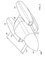
Figure 2 is a perspective view of the rotor system, according to the preferred embodiment of the present application; -
Figure 3 is a perspective view of the rotor system, according to the preferred embodiment of the present application; -
Figure 4 is a perspective view of the rotor system, according to the preferred embodiment of the present application; -
Figure 5 is a partial perspective view of the rotor system, according to the preferred embodiment of the present application; -
Figure 6 is a partial perspective view of the rotor system, according to the preferred embodiment of the present application; -
Figure 7 is a partial perspective view of the rotor system, according to the preferred embodiment of the present application; -
Figure 8 is a perspective view of a tilt rotor aircraft, according to an alternative embodiment of the present application; -
Figure 9 is a perspective view of the rotor system, according to an alternative embodiment of the present application; and -
Figure 10 is a partial perspective view of the rotor system, according to an alternative embodiment of the present application. - Illustrative embodiments of the system of the present application are described below. In the interest of clarity, not all features of an actual implementation are described in this specification. It will of course be appreciated that in the development of any such actual embodiment, numerous implementation-specific decisions must be made to achieve the developer's specific goals, such as compliance with system-related and business-related constraints, which will vary from one implementation to another. Moreover, it will be appreciated that such a development effort might be complex and time-consuming but would nevertheless be a routine undertaking for those of ordinary skill in the art having the benefit of this disclosure.
- In the specification, reference may be made to the spatial relationships between various components and to the spatial orientation of various aspects of components as the devices are depicted in the attached drawings. However, as will be recognized by those skilled in the art after a complete reading of the present application, the devices, members, apparatuses, etc. described herein may be positioned in any desired orientation. Thus, the use of terms such as "above," "below," "upper," "lower," or other like terms to describe a spatial relationship between various components or to describe the spatial orientation of aspects of such components should be understood to describe a relative relationship between the components or a spatial orientation of aspects of such components, respectively, as the device described herein may be oriented in any desired direction.
- The system of the present application includes an engine and pylon arrangement for a tilt rotor aircraft in which the engine is fixed in relation to a wing portion of the aircraft, while the pylon is rotatable. The pylon supports a rotor hub having a plurality of rotor blades. Rotation of the pylon allows the aircraft to selectively fly in a helicopter mode and an airplane mode, as well as any combination thereof.
- Referring to
Figure 1 , atilt rotor aircraft 101 is illustrated. In the illustrated embodiment,tilt rotor aircraft 101 includes afuselage 103, awing member 105, and atail member 107.Aircraft 101 further includes afirst rotor system 109a and asecond rotor system 109b.First rotor system 109a is located on a left end portion ofwing member 105, whilesecond rotor system 109b is located on a right end portion ofwing member 105.First rotor system 109a andsecond rotor system 109b are substantially symmetric of each other. In the interest of clarity, onlyfirst rotor system 109a will be discussed in detail. However, one of ordinary skill in the art will understand that the form and function ofsecond rotor system 109b will be fully known from the benefit of the disclosure herein related tofirst rotor system 109a. Furthermore,first rotor system 109a andsecond rotor system 109b each includerotor blades rotor blades - It should be appreciated that even though
first rotor system 109a andsecond rotor system 109b are illustrated ontilt rotor aircraft 101,first rotor system 109a andsecond rotor system 109b can be implemented on other tilt rotor aircraft. For example, an alternative embodiment can include a quad tilt rotor aircraft that has an additional wing member located aft ofwing member 105, the additional wing member can have additional rotor systems similar tofirst rotor system 109a andsecond rotor system 109b. Another alternative embodiment can include an unmanned version oftilt rotor aircraft 101. Further,first rotor system 109a andsecond rotor system 109b can be integrated into a variety of tilt rotor aircraft configurations. - Referring now to
Figures 2 and3 ,rotor system 109a is illustrated in an airplane mode and a helicopter mode, respectively.Rotor system 109a includes an outboardfixed engine nacelle 113 and an inboardfixed engine nacelle 115. A prop-rotor pylon 119 includes a plurality ofrotor blades 111a (shown inFigure 1 ) coupled to internal rotor structure located within anaerodynamic spinner fairing 121. Prop-rotor pylon 119 includes anacelle fairing 123 that is configured to rotate along with other rotatable pylon structure.Rotor system 109a can include amoveable fairing panel 125 that can be actuated in the aft direction in order to provide rotational clearance fornacelle fairing 123 when prop-rotor pylon 119 is actuated into helicopter mode. Further,moveable fairing panel 125 is actuated forward when prop-rotor pylon 119 is actuated into airplane mode so as to improve aerodynamic airflow about the aft portion of prop-rotor pylon 119.Moveable fairing panel 125 can be actuated with an independent actuator, or can be mechanically coupled to the actuator system used for actuating prop-rotor pylon 119 between airplane mode and helicopter mode. - Prop-
rotor pylon 119 is rotatable between the airplane mode, in which prop-rotor pylon 119 is positioned approximately horizontal (as shown inFigure 2 ), and a helicopter mode (as shown inFigure 3 ), in which prop-rotor pylon 119 is positioned approximately vertical. During the airplane mode, vertical lift is primarily supplied by the airfoil profile ofwing member 105, whilerotor blades rotor pylon 119 provide forward thrust. During the helicopter mode, vertical lift is primarily supplied by the thrust ofrotor blades rotor pylon 119. It should be appreciated thattilt rotor aircraft 101 may be operated such that prop-rotor pylons 119 are selectively positioned between airplane mode and helicopter mode, which can be referred to as a conversion mode. -
Rotor system 109a can include apylon downstop 127 for securing prop-rotor pylon 119 when prop-rotor pylon 119 is positioned in the airplane mode. Further,pylon downstop 127 can be beneficial for relieving stresses on the actuator(s), such as aconversion actuator 133, used for selectively rotating prop-rotor pylon 119 between airplane mode position and helicopter mode position. - Outboard
fixed engine nacelle 113 includes an outboardengine air inlet 114. Similarly, inboardfixed engine nacelle 115 includes an inboardengine air inlet 116.Air inlets edge portion 117 ofwing member 105; however, an alternative embodiment can include the positioning ofair inlets edge portion 117 ofwing member 105. The exact position ofair inlets - It should be appreciated that the wing tip portion of
wing member 105 can be lengthened to customize an aspect ratio ofwing member 105 in accordance with implementation specific aerodynamic lift requirements. As such, it should be understood that even though outboard fixedengine nacelle 113 is illustrated approximately abutting the wing tip portion ofwing member 105, an alternative embodiment may include the wing tip portion extending well beyond outboard fixedengine nacelle 113. - When
rotor system 109a is in helicopter mode, airflow downwash fromrotor blades wing member 105, thereby negatively affecting vertical lift performance. Inboard fixedengine nacelle 115 is located in part to act as an air dam to thwart downwash airflow along the upper surface ofwing member 105, the downwash airflow being in the direction from the root end to the tip end ofwing member 105. - Referring now also to
Figures 4-7 ,rotor system 109a is illustrated in further detail. Aswashplate 129 is coupledrotor blades 111a via a plurality of pitch links (not shown). Swashplate actuators 131a-131c are configured to selectively actuateswashplate 129, thereby selectively changing the pitch ofrotor blades 111a so as to affect thrust, lift, and direction ofaircraft 101 during operation. For example,swashplate 129 can be selectively tilted to effect cyclic pitch change ofrotor blades 111a. Further,swashplate 129 can be actuated to effect collective pitch change ofrotor blades 111a. Aconversion actuator 133 is configured to selectively actuate prop-rotor pylon 119 between a helicopter mode position and an airplane mode position, while theengines wing member 105. It should be appreciated thatconversion actuator 133 may be of a variety of configurations. For example,conversion actuator 133 may be a linear actuator or a rotary actuator, the exact actuator type being implementation specific. A prop-rotor gearbox housing 143 of prop-rotor pylon 119 is pivotally mounted on anoutboard rib bearing 139 within anoutboard rib 135, and aninboard rib bearing 141 within aninboard rib 137. - An
outboard engine 145 and aninboard engine 147 can be structurally mounted on anengine support beam 149 near a trailing edge portion ofwing member 105.Outboard engine 145 is mechanically coupled to anoutboard input gearbox 151, via anoutboard input driveshaft 155, such that torque is transferred tooutboard input gearbox 151 fromoutboard engine 145. Similarly,inboard engine 147 is mechanically coupled to aninboard input gearbox 153, via aninboard input driveshaft 157, such that torque is transferred toinboard input gearbox 153 frominboard engine 147. Torque is transferred to amain rotor mast 163 fromoutboard input gearbox 155 and inboard input gearbox via anoutboard gearbox driveshaft 159 and an inboard gearbox driveshaft, respectively. -
Inboard input gearbox 153 can optionally be coupled to anaccessory input gearbox 165 and further aninterconnect drive shaft 167.Interconnect drive shaft 167 can be used to drive an auxiliary gearbox located withinfuselage 103. In an alternative embodiment,interconnect drive shaft 167 can be sized to carry torque sufficient to driverotor blades 111b onrotor system 109b, which can provide an additional safety factor in an engine failure situation. - The configuration of
rotor system 109a allowsengines wing member 105, while only prop-rotor pylon 119 rotates to allowaircraft 101 to fly both in a helicopter mode, an airplane mode, and conversion mode. Attempts have been made in prior tilt rotor aircraft configurations to locate fixed engines within a fuselage of the aircraft; however, such a configuration requires an interconnect drive system to carry full engine power out to the wing tip mounted rotor and prop-rotor drive gearboxes, which can degrade safety and reliability of the drive system. In contrast,rotor system 109a is configured such that theengines rotor pylon 119, so that only a short input shaft system is required to carry full engine power. As such, the short input drive shaft system from each engine to the proprotor pylon provides increased safety, reliability, and efficiency. In the illustrated embodiment, full engine power is carried ininput driveshafts gearbox drive shafts engines rotor systems rotor systems rotor system 109a with fixed engines, instead of engines that rotate, results in a significant reduction in engine certification costs, complexity, and expense. Furthermore, arotor system 109a with fixed engines, instead of engines that rotate, can provide a substantial increase in engine options and availabilities, thus contributing to aircraft cost reduction. - Referring now to
Figures 8-10 , atilt rotor aircraft 801 is illustrated as an alternative embodiment oftilt rotor aircraft 101.Tilt rotor aircraft 801 is substantially similar in form and function to tiltrotor aircraft 801, except as noted herein. For example,tilt rotor aircraft 801 is different fromtilt rotor aircraft 101 in that inboard fixedengine nacelle 115 is omitted inrotor systems tilt rotor aircraft 801 has only a single fixed engine in eachrotor system optional wing fence 803 can be utilized to act as an air dam to thwart downwash airflow along the upper surface ofwing member 105, the downwash airflow being in the direction from the root end to the tip end ofwing member 105. Whiletilt rotor aircraft 801 has only asingle engine 145 for powering prop-rotor pylon 119, it can be especially desirable forinterconnect drive shaft 167 to be sized to carry torque sufficient to driverotor blades 111b onrotor system 809b, which can provide an additional safety factor in an engine failure situation. In the illustrated embodiment,inboard input gearbox 153 mechanically transmits power fromoutboard engine 145 toaccessory input gearbox 165 and further to interconnectdrive shaft 167. It should be understood that the exact configuration of the drive shafts and gearboxes is implementation specific. - It is apparent that a rotor system with significant advantages has been described and illustrated. The tilt rotor fixed engine system provides for a horizontal, permanent engine mounting which reduces certification costs, increases available engine choices, and reduces maintenance costs and scheduled maintenance times. The proximity of the fixed engines to the rotating pylon also increases safety with regard to drive shaft failures, bearing lives, and coupling needs. Although the system of the present application is shown in a limited number of forms, it is not limited to just these forms, but is amenable to various changes and modifications without departing from the spirit thereof.
Claims (14)
- A rotor system for a tilt rotor aircraft, the rotor system comprising:an outboard engine in a first fixed location on a wing member of the tilt rotor aircraft; anda prop-rotor pylon in power communication with the outboard engine, the prop-rotor pylon being configured to selectively rotate between a vertical position and a horizontal position, the prop-rotor pylon comprising a plurality of rotor blades.
- The rotor system according to claim 1, wherein the outboard engine is located outboard of the prop-rotor pylon.
- A tilt rotor aircraft comprising:a fuselage;a wing member;an outboard engine in a first fixed location on the wing member of the tilt rotor aircraft; anda prop-rotor pylon powered by the outboard engine, the prop-rotor pylon being configured to selectively rotate between a vertical position and a horizontal position, the prop-rotor pylon comprising a plurality of rotor blades.
- The tilt rotor aircraft according to claim 3, wherein the outboard engine is located outboard of the prop-rotor pylon, the outboard engine and the prop-rotor pylon being located on an outboard portion of the wing member, the outboard portion being a selected distance from the fuselage.
- The rotor system or tilt rotor aircraft according to any preceding claim, the prop-rotor pylon further comprising:a swashplate;a gearbox; anda nacelle fairing configured as an aerodynamic housing for the swashplate and the gearbox.
- The rotor system or tilt rotor aircraft according to any preceding claim, further comprising:an outboard input drive shaft coupled between the outboard engine and an outboard input gearbox; andan outboard gearbox drive shaft coupled between the outboard input gearbox and a gearbox located in the prop-rotor pylon.
- The rotor system or tilt rotor aircraft according to claim 6, wherein the outboard gearbox drive shaft traverses through an interior of an outboard rib bearing, the outboard rib bearing providing rotational support for the prop-rotor pylon against a fixed outboard rib member.
- The rotor system or tilt rotor aircraft according to any preceding claim, the prop-rotor pylon further comprising:a nacelle fairing configured as an aerodynamic housing for internal components located therein;a fairing panel located aft of the nacelle fairing, the fairing panel being moveable between a closed position and an open position, the closed position providing aerodynamic efficiency when the prop-rotor pylon is the horizontal position, the open position providing clearance for the prop-rotor pylon to rotate into the vertical position.
- The rotor system or tilt rotor aircraft according to any preceding claim, further comprising:an inboard engine in a second fixed location on the wing member of the tilt rotor aircraft.
- The rotor system or tilt rotor aircraft according to claim 9, further comprising:an inboard input drive shaft coupled between the inboard engine and an inboard input gearbox; andan inboard gearbox drive shaft coupled between the inboard input gearbox and a gearbox located in the prop-rotor pylon.
- The rotor system or tilt rotor aircraft according to claim 10, further comprising:an accessory drive shaft coupled between the inboard input gearbox and an accessory input gearbox;an interconnect drive shaft coupled to the accessory input gearbox.
- The rotor system or tilt rotor aircraft according to claim 11, wherein the interconnect drive shaft is coupled to an accessory gearbox located in a fuselage portion of the aircraft.
- The rotor system or tilt rotor aircraft according to claim 11, wherein the interconnect drive shaft is coupled to a gearbox configured for drive a second prop-rotor pylon located on an opposite portion of the wing member.
- The rotor system or tilt rotor aircraft according to any preceding claim, further comprising:a conversion actuator configured to selectively rotate the prop-rotor pylon.
Applications Claiming Priority (2)
| Application Number | Priority Date | Filing Date | Title |
|---|---|---|---|
| US201161439547P | 2011-02-04 | 2011-02-04 | |
| US13/357,981 US8602347B2 (en) | 2011-02-04 | 2012-01-25 | Tilt rotor aircraft with fixed engine arrangement |
Publications (2)
| Publication Number | Publication Date |
|---|---|
| EP2484587A1 true EP2484587A1 (en) | 2012-08-08 |
| EP2484587B1 EP2484587B1 (en) | 2014-03-19 |
Family
ID=45558617
Family Applications (1)
| Application Number | Title | Priority Date | Filing Date |
|---|---|---|---|
| EP12153373.1A Active EP2484587B1 (en) | 2011-02-04 | 2012-01-31 | Tilt rotor aircraft with fixed engine arrangement |
Country Status (5)
| Country | Link |
|---|---|
| US (2) | US8602347B2 (en) |
| EP (1) | EP2484587B1 (en) |
| CN (1) | CN102627146B (en) |
| CA (1) | CA2766623C (en) |
| IN (1) | IN2012DE00256A (en) |
Cited By (7)
| Publication number | Priority date | Publication date | Assignee | Title |
|---|---|---|---|---|
| EP2778063A1 (en) * | 2013-03-12 | 2014-09-17 | Bell Helicopter Textron Inc. | Tiltrotor aircraft with inboard wing mounted fixed engine arrangement |
| EP2837559A1 (en) * | 2013-08-14 | 2015-02-18 | Bell Helicopter Textron Inc. | Fixed engine and rotating proprotor arrangement for a tiltrotor aircraft |
| US9126678B2 (en) | 2013-03-13 | 2015-09-08 | Bell Helicopter Textron Inc. | Spindle mounted tiltrotor pylon with fixed engine arrangement |
| US9834303B2 (en) | 2013-08-14 | 2017-12-05 | Bell Helicopter Textron Inc. | Method and apparatus of connecting a fixed drive system to a rotating drive system for a tiltrotor aircraft |
| EP3415425A1 (en) * | 2017-06-16 | 2018-12-19 | Bell Helicopter Textron Inc. | Tiltrotor outboard fixed engine configuration with offset rotation spindle and interconnect drive shaft |
| EP3604130A1 (en) * | 2018-07-31 | 2020-02-05 | Bell Helicopter Textron Inc. | System and method for rotating a rotor of a tiltrotor aircraft |
| US10913542B2 (en) | 2018-07-27 | 2021-02-09 | Textron Innovations Inc. | Conversion actuator and downstop striker fitting for a tiltrotor aircraft |
Families Citing this family (65)
| Publication number | Priority date | Publication date | Assignee | Title |
|---|---|---|---|---|
| US8602347B2 (en) * | 2011-02-04 | 2013-12-10 | Textron Innovations Inc. | Tilt rotor aircraft with fixed engine arrangement |
| CN103721421A (en) * | 2012-10-16 | 2014-04-16 | 田瑜 | Aircraft with a plurality of rotors |
| US9540113B2 (en) * | 2013-03-11 | 2017-01-10 | United Technologies Corporation | De-couple geared turbo-fan engine and aircraft |
| US9809318B1 (en) * | 2013-08-14 | 2017-11-07 | Bell Helicopter Textron Inc. | Tiltrotor aircraft having spherical bearing mounted pylon assemblies |
| US9663225B1 (en) * | 2013-08-14 | 2017-05-30 | Bell Helicopter Textron Inc. | Maintaining drive system alignment in tiltrotor aircraft |
| US9868541B2 (en) * | 2013-08-14 | 2018-01-16 | Bell Helicopter Textron Inc. | Tiltrotor aircraft having journal bearing mounted pylon assemblies |
| US9868542B2 (en) * | 2013-08-14 | 2018-01-16 | Bell Helicopter Textron Inc. | Tiltrotor aircraft having pillow block mounted pylon assemblies |
| US9856029B2 (en) * | 2013-08-14 | 2018-01-02 | Bell Helicopter Textron Inc. | Tiltrotor aircraft having tip rib mounted pylon assemblies |
| US10046855B2 (en) * | 2014-03-18 | 2018-08-14 | Joby Aero, Inc. | Impact resistant propeller system, fast response electric propulsion system and lightweight vertical take-off and landing aircraft using same |
| US10315760B2 (en) * | 2014-03-18 | 2019-06-11 | Joby Aero, Inc. | Articulated electric propulsion system with fully stowing blades and lightweight vertical take-off and landing aircraft using same |
| US10625852B2 (en) * | 2014-03-18 | 2020-04-21 | Joby Aero, Inc. | Aerodynamically efficient lightweight vertical take-off and landing aircraft with pivoting rotors and stowing rotor blades |
| US9694911B2 (en) * | 2014-03-18 | 2017-07-04 | Joby Aviation, Inc. | Aerodynamically efficient lightweight vertical take-off and landing aircraft with pivoting rotors and stowing rotor blades |
| CN103979105B (en) * | 2014-05-23 | 2015-11-18 | 深圳市艾特航空科技股份有限公司 | A kind of vertical takeoff and landing adjustable wing aircraft |
| CN103979103A (en) * | 2014-06-03 | 2014-08-13 | 杭州策引东机电有限公司 | Tilt rotor airplane with novel structure |
| US9475585B2 (en) * | 2014-06-25 | 2016-10-25 | The Boeing Company | Tilt-rotor vertical-lift aircraft |
| IL233902B (en) * | 2014-07-31 | 2020-07-30 | Israel Aerospace Ind Ltd | egnition system |
| US9841333B2 (en) * | 2014-10-29 | 2017-12-12 | Bell Helicopter Textron Inc. | Method and system for measuring torque in a tiltrotor aircraft |
| US10239610B2 (en) * | 2015-03-10 | 2019-03-26 | Bell Helicopter Textron Inc. | Compact linear hydraulic actuator |
| US10183745B2 (en) * | 2015-12-07 | 2019-01-22 | Bell Helicopter Textron Inc. | Tiltrotor with inboard engines |
| CN105923154B (en) * | 2016-06-01 | 2019-03-12 | 北京航空航天大学 | Tandem twin-rotor fixed-wing compound vertical take-off and landing vehicle |
| US10384773B2 (en) | 2016-09-08 | 2019-08-20 | General Electric Company | Tiltrotor propulsion system for an aircraft |
| US10252797B2 (en) | 2016-09-08 | 2019-04-09 | General Electric Company | Tiltrotor propulsion system for an aircraft |
| US10392106B2 (en) | 2016-09-08 | 2019-08-27 | General Electric Company | Tiltrotor propulsion system for an aircraft |
| US10384774B2 (en) | 2016-09-08 | 2019-08-20 | General Electric Company | Tiltrotor propulsion system for an aircraft |
| USD808328S1 (en) | 2016-09-14 | 2018-01-23 | Bell Helicopter Textron Inc. | Foldable tiltrotor aircraft |
| US10507930B2 (en) * | 2016-11-22 | 2019-12-17 | Rolls-Royce North American Technologies Inc. | Airplane with angled-mounted turboprop engine |
| IL249908B (en) | 2016-12-28 | 2021-12-01 | Israel Aerospace Ind Ltd | Aircraft pylon |
| US11046446B2 (en) | 2017-03-02 | 2021-06-29 | Bell Helicopter Textron Inc. | Tiltrotor aircraft rotating proprotor assembly |
| US10533603B2 (en) | 2017-03-02 | 2020-01-14 | Bell Helicopter Textron Inc. | Roller track assembly for a tiltrotor proprotor door |
| US10539180B2 (en) | 2017-03-02 | 2020-01-21 | Bell Helicopter Textron Inc. | Bogie mechanism for a tiltrotor proprotor door |
| US10994853B2 (en) | 2017-03-02 | 2021-05-04 | Bell Helicopter Textron Inc. | Tiltrotor aircraft rotating proprotor assembly |
| EP3583027A4 (en) * | 2017-03-09 | 2020-03-04 | Shafir, Yehuda | VERTICAL STARTING AND LANDING LIGHT AIRCRAFT |
| JP6955280B2 (en) | 2017-05-22 | 2021-10-27 | オーバーエアー インコーポレイテッドOverair,Inc. | Electric VTOL aircraft |
| US10589855B2 (en) | 2017-06-13 | 2020-03-17 | Bell Helicopter Textron Inc. | Tiltrotor aircraft with outboard fixed engines |
| US10822101B2 (en) | 2017-07-21 | 2020-11-03 | General Electric Company | Vertical takeoff and landing aircraft having a forward thrust propulsor |
| US10994852B2 (en) | 2018-04-05 | 2021-05-04 | Bell Helicopter Textron Inc. | Door for a tiltrotor proprotor pylon |
| CN108382578B (en) * | 2018-04-09 | 2024-03-29 | 北京航空航天大学 | High-speed hybrid layout vertical take-off and landing aircraft |
| US10875627B2 (en) | 2018-05-01 | 2020-12-29 | Bell Helicopter Textron Inc. | Movable cover for a proprotor nacelle |
| US11230388B2 (en) | 2018-05-09 | 2022-01-25 | Textron Innovations Inc. | Stowable wing aircraft with dual, fuselage-mounted engines |
| KR102594866B1 (en) | 2018-05-10 | 2023-10-30 | 조비 에어로, 인크. | electric tiltrotor aircraft |
| CN121553374A (en) | 2018-05-31 | 2026-02-24 | 杰欧比飞行有限公司 | Electric power system architecture and fault tolerant VTOL aircraft using the same |
| US12006048B2 (en) | 2018-05-31 | 2024-06-11 | Joby Aero, Inc. | Electric power system architecture and fault tolerant VTOL aircraft using same |
| JP7130064B2 (en) | 2018-06-01 | 2022-09-02 | ジョビー エアロ,インコーポレイテッド | Aircraft noise abatement system and method |
| US11338916B2 (en) * | 2018-06-21 | 2022-05-24 | Textron Innovations Inc. | Engine and rotatable proprotor configurations for a tiltrotor aircraft |
| US11148798B2 (en) * | 2018-06-22 | 2021-10-19 | Textron Innovations Inc. | Engine and rotatable proprotor configurations for a tiltrotor aircraft |
| US10710741B2 (en) | 2018-07-02 | 2020-07-14 | Joby Aero, Inc. | System and method for airspeed determination |
| EP3853736B1 (en) | 2018-09-17 | 2025-10-22 | Joby Aero, Inc. | Aircraft control system |
| USD974276S1 (en) | 2018-11-15 | 2023-01-03 | Textron Innovations, Inc. | Aircraft spinner |
| USD909949S1 (en) | 2018-11-15 | 2021-02-09 | Bell Helicopter Textron Inc. | Tiltrotor aircraft |
| USD909278S1 (en) | 2018-11-15 | 2021-02-02 | Bell Helicopter Textron Inc. | Foldable tiltrotor aircraft |
| USD974277S1 (en) | 2018-11-15 | 2023-01-03 | Textron Innovations, Inc. | Aircraft payload enclosure |
| JP7401545B2 (en) | 2018-12-07 | 2023-12-19 | ジョビー エアロ インク | Rotor blades and their design methods |
| EP3891067B1 (en) | 2018-12-07 | 2024-01-17 | Joby Aero, Inc. | Aircraft control system and method |
| EP3899427B1 (en) | 2018-12-19 | 2025-09-03 | Joby Aero, Inc. | Vehicle navigation system |
| USD942545S1 (en) | 2019-04-17 | 2022-02-01 | Target Brands, Inc. | Display fixture |
| CN114041229B (en) | 2019-04-23 | 2023-06-16 | 杰欧比飞行有限公司 | Battery thermal management system and method |
| US11230384B2 (en) | 2019-04-23 | 2022-01-25 | Joby Aero, Inc. | Vehicle cabin thermal management system and method |
| CN114423679A (en) | 2019-04-25 | 2022-04-29 | 杰欧比飞行有限公司 | Vertical take-off and landing aircraft |
| US11673649B2 (en) | 2020-06-05 | 2023-06-13 | Joby Aero, Inc. | Aircraft control system and method |
| US11745867B2 (en) * | 2020-12-11 | 2023-09-05 | Textron Innovations Inc. | Pylon conversion actuator for tiltrotor aircraft |
| USD988226S1 (en) * | 2021-02-24 | 2023-06-06 | Joby Aero, Inc. | Aircraft |
| CN113060279B (en) * | 2021-04-22 | 2024-09-17 | 北京金璐东方联合物流有限公司 | Aircraft |
| CN113320694B (en) * | 2021-07-13 | 2023-08-18 | 广东汇天航空航天科技有限公司 | Tilt rotor mechanism and aircraft with same |
| CN113335504A (en) * | 2021-08-09 | 2021-09-03 | 中国空气动力研究与发展中心空天技术研究所 | Rotor wing fairing of composite wing aircraft |
| CN115771614B (en) * | 2023-02-14 | 2023-06-13 | 江苏新扬新材料股份有限公司 | Large-scale gyroplane transmission system that verts |
Citations (4)
| Publication number | Priority date | Publication date | Assignee | Title |
|---|---|---|---|---|
| US3592412A (en) | 1969-10-03 | 1971-07-13 | Boeing Co | Convertible aircraft |
| FR2791319A1 (en) * | 1999-03-25 | 2000-09-29 | Eurocopter France | Turboprop aircraft with engine pods mounted on the main wing tips, comprises rotating front sections enabling very short/vertical take off capability |
| EP1057724A2 (en) * | 1999-06-02 | 2000-12-06 | Agusta S.p.A. | Tilt-rotor aircraft |
| US20060016930A1 (en) | 2004-07-09 | 2006-01-26 | Steve Pak | Sky hopper |
Family Cites Families (11)
| Publication number | Priority date | Publication date | Assignee | Title |
|---|---|---|---|---|
| US2974900A (en) * | 1959-03-11 | 1961-03-14 | Doak Aircraft Co Inc | Aircraft flight control system |
| US3136499A (en) * | 1962-11-15 | 1964-06-09 | North American Aviation Inc | Aircraft power transmission system |
| US3284027A (en) * | 1964-01-09 | 1966-11-08 | Nord Aviation | Vtol aircraft having freely pivoted propulsion means |
| US3586262A (en) * | 1969-12-05 | 1971-06-22 | Irving Robert Sherman | Foreflapped airfoil |
| US4979698A (en) * | 1988-07-07 | 1990-12-25 | Paul Lederman | Rotor system for winged aircraft |
| US5823470A (en) * | 1996-07-16 | 1998-10-20 | Mcdonnell Douglas Helicopter Co. | Split torque proprotor transmission |
| FR2798359B1 (en) * | 1999-09-14 | 2001-11-09 | Eurocopter France | IMPROVEMENTS ON TILTING ROTOR CONVERTIBLE AIRCRAFT |
| US6659394B1 (en) * | 2000-05-31 | 2003-12-09 | The United States Of America As Represented By The Secretary Of The Air Force | Compound tilting wing for high lift stability and control of aircraft |
| CN2507780Y (en) * | 2001-11-02 | 2002-08-28 | 熊伟 | Small tilting rotor commercial aircraft |
| US8292216B1 (en) * | 2009-12-16 | 2012-10-23 | The Boeing Company | Wing lift system |
| US8602347B2 (en) * | 2011-02-04 | 2013-12-10 | Textron Innovations Inc. | Tilt rotor aircraft with fixed engine arrangement |
-
2012
- 2012-01-25 US US13/357,981 patent/US8602347B2/en active Active
- 2012-01-31 IN IN256DE2012 patent/IN2012DE00256A/en unknown
- 2012-01-31 EP EP12153373.1A patent/EP2484587B1/en active Active
- 2012-02-02 CA CA2766623A patent/CA2766623C/en active Active
- 2012-02-06 CN CN201210026136.0A patent/CN102627146B/en not_active Expired - Fee Related
-
2013
- 2013-12-10 US US14/101,953 patent/US9199732B2/en active Active
Patent Citations (4)
| Publication number | Priority date | Publication date | Assignee | Title |
|---|---|---|---|---|
| US3592412A (en) | 1969-10-03 | 1971-07-13 | Boeing Co | Convertible aircraft |
| FR2791319A1 (en) * | 1999-03-25 | 2000-09-29 | Eurocopter France | Turboprop aircraft with engine pods mounted on the main wing tips, comprises rotating front sections enabling very short/vertical take off capability |
| EP1057724A2 (en) * | 1999-06-02 | 2000-12-06 | Agusta S.p.A. | Tilt-rotor aircraft |
| US20060016930A1 (en) | 2004-07-09 | 2006-01-26 | Steve Pak | Sky hopper |
Cited By (12)
| Publication number | Priority date | Publication date | Assignee | Title |
|---|---|---|---|---|
| EP2778063A1 (en) * | 2013-03-12 | 2014-09-17 | Bell Helicopter Textron Inc. | Tiltrotor aircraft with inboard wing mounted fixed engine arrangement |
| US9376206B2 (en) | 2013-03-12 | 2016-06-28 | Bell Helicopter Textron Inc. | Tiltrotor aircraft with inboard wing mounted fixed engine arrangement |
| US9126678B2 (en) | 2013-03-13 | 2015-09-08 | Bell Helicopter Textron Inc. | Spindle mounted tiltrotor pylon with fixed engine arrangement |
| EP2837559A1 (en) * | 2013-08-14 | 2015-02-18 | Bell Helicopter Textron Inc. | Fixed engine and rotating proprotor arrangement for a tiltrotor aircraft |
| US9174731B2 (en) | 2013-08-14 | 2015-11-03 | Bell Helicopter Textron Inc. | Fixed engine and rotating proprotor arrangement for a tiltrotor aircraft |
| US9834303B2 (en) | 2013-08-14 | 2017-12-05 | Bell Helicopter Textron Inc. | Method and apparatus of connecting a fixed drive system to a rotating drive system for a tiltrotor aircraft |
| EP3415425A1 (en) * | 2017-06-16 | 2018-12-19 | Bell Helicopter Textron Inc. | Tiltrotor outboard fixed engine configuration with offset rotation spindle and interconnect drive shaft |
| US10654580B2 (en) | 2017-06-16 | 2020-05-19 | Bell Helipcopter Textron Inc. | Tiltrotor outboard fixed engine configuration with offset rotation spindle and interconnect drive shaft |
| US10913542B2 (en) | 2018-07-27 | 2021-02-09 | Textron Innovations Inc. | Conversion actuator and downstop striker fitting for a tiltrotor aircraft |
| EP3604130A1 (en) * | 2018-07-31 | 2020-02-05 | Bell Helicopter Textron Inc. | System and method for rotating a rotor of a tiltrotor aircraft |
| US10994839B2 (en) | 2018-07-31 | 2021-05-04 | Textron Innovations Inc. | System and method for rotating a rotor of a tiltrotor aircraft |
| US11787536B2 (en) | 2018-07-31 | 2023-10-17 | Textron Innovations Inc. | System and method for rotating a rotor of a tiltrotor aircraft |
Also Published As
| Publication number | Publication date |
|---|---|
| IN2012DE00256A (en) | 2015-07-10 |
| CN102627146B (en) | 2016-08-03 |
| US8602347B2 (en) | 2013-12-10 |
| US20140217243A1 (en) | 2014-08-07 |
| CA2766623A1 (en) | 2012-08-04 |
| US20120199699A1 (en) | 2012-08-09 |
| US9199732B2 (en) | 2015-12-01 |
| CN102627146A (en) | 2012-08-08 |
| CA2766623C (en) | 2015-09-08 |
| EP2484587B1 (en) | 2014-03-19 |
Similar Documents
| Publication | Publication Date | Title |
|---|---|---|
| US8602347B2 (en) | Tilt rotor aircraft with fixed engine arrangement | |
| EP2778063B1 (en) | Tiltrotor aircraft with inboard wing mounted fixed engine arrangement | |
| US10526068B2 (en) | Tilrotor aircraft having rotary and non rotary flight modes | |
| US9126678B2 (en) | Spindle mounted tiltrotor pylon with fixed engine arrangement | |
| EP3299290B1 (en) | Rotating proprotor arrangement for a tiltrotor aircraft | |
| US8567709B2 (en) | Rotorcraft with variable incident wing | |
| US20180354616A1 (en) | Tiltrotor aircraft with outboard fixed engines | |
| US20120061509A1 (en) | Co-Rotating Stacked Rotor Disks for Improved Hover Performance | |
| US9139298B2 (en) | Rotorcraft control system for rotorcraft with two or more rotor systems | |
| CN102770345A (en) | Rotor hub and controls for multi-bladed rotor system | |
| KR102010964B1 (en) | Vertical takeoff and landing type hybrid drones | |
| US20220281594A1 (en) | Engine comprising a movable aerodynamic component | |
| EP1957363B1 (en) | Rotorcraft control system and method of using | |
| EP3360780B1 (en) | Tiltrotor aircraft having rotary and non rotary flight modes | |
| US10086935B2 (en) | Guide vanes for a pusher propeller for rotary wing aircraft | |
| US20200231293A1 (en) | Dedicated core inflow inlet for convertible engine | |
| EP3177525A1 (en) | Flex beam for rotor assembly | |
| US20170137121A1 (en) | Flex beam clamp for rotor assembly | |
| US11117655B2 (en) | Counter-rotating tail rotor | |
| US11305871B2 (en) | Passive rotor alignment in a free-wheeling state | |
| EP3998196A1 (en) | Aircraft engine comprising a variable area exhaust nozzle | |
| KR101150855B1 (en) | Flight control structure of duct type flight robot | |
| EP2873612B1 (en) | Counter-rotating rotor system with fairing |
Legal Events
| Date | Code | Title | Description |
|---|---|---|---|
| PUAI | Public reference made under article 153(3) epc to a published international application that has entered the european phase |
Free format text: ORIGINAL CODE: 0009012 |
|
| 17P | Request for examination filed |
Effective date: 20120131 |
|
| AK | Designated contracting states |
Kind code of ref document: A1 Designated state(s): AL AT BE BG CH CY CZ DE DK EE ES FI FR GB GR HR HU IE IS IT LI LT LU LV MC MK MT NL NO PL PT RO RS SE SI SK SM TR |
|
| AX | Request for extension of the european patent |
Extension state: BA ME |
|
| 17Q | First examination report despatched |
Effective date: 20130809 |
|
| GRAP | Despatch of communication of intention to grant a patent |
Free format text: ORIGINAL CODE: EPIDOSNIGR1 |
|
| INTG | Intention to grant announced |
Effective date: 20140102 |
|
| GRAS | Grant fee paid |
Free format text: ORIGINAL CODE: EPIDOSNIGR3 |
|
| GRAA | (expected) grant |
Free format text: ORIGINAL CODE: 0009210 |
|
| AK | Designated contracting states |
Kind code of ref document: B1 Designated state(s): AL AT BE BG CH CY CZ DE DK EE ES FI FR GB GR HR HU IE IS IT LI LT LU LV MC MK MT NL NO PL PT RO RS SE SI SK SM TR |
|
| REG | Reference to a national code |
Ref country code: GB Ref legal event code: FG4D |
|
| REG | Reference to a national code |
Ref country code: CH Ref legal event code: EP |
|
| REG | Reference to a national code |
Ref country code: IE Ref legal event code: FG4D |
|
| REG | Reference to a national code |
Ref country code: AT Ref legal event code: REF Ref document number: 657491 Country of ref document: AT Kind code of ref document: T Effective date: 20140415 |
|
| REG | Reference to a national code |
Ref country code: DE Ref legal event code: R096 Ref document number: 602012001071 Country of ref document: DE Effective date: 20140430 |
|
| PG25 | Lapsed in a contracting state [announced via postgrant information from national office to epo] |
Ref country code: LT Free format text: LAPSE BECAUSE OF FAILURE TO SUBMIT A TRANSLATION OF THE DESCRIPTION OR TO PAY THE FEE WITHIN THE PRESCRIBED TIME-LIMIT Effective date: 20140319 Ref country code: NO Free format text: LAPSE BECAUSE OF FAILURE TO SUBMIT A TRANSLATION OF THE DESCRIPTION OR TO PAY THE FEE WITHIN THE PRESCRIBED TIME-LIMIT Effective date: 20140619 |
|
| REG | Reference to a national code |
Ref country code: NL Ref legal event code: VDEP Effective date: 20140319 |
|
| REG | Reference to a national code |
Ref country code: AT Ref legal event code: MK05 Ref document number: 657491 Country of ref document: AT Kind code of ref document: T Effective date: 20140319 |
|
| REG | Reference to a national code |
Ref country code: LT Ref legal event code: MG4D |
|
| PG25 | Lapsed in a contracting state [announced via postgrant information from national office to epo] |
Ref country code: SE Free format text: LAPSE BECAUSE OF FAILURE TO SUBMIT A TRANSLATION OF THE DESCRIPTION OR TO PAY THE FEE WITHIN THE PRESCRIBED TIME-LIMIT Effective date: 20140319 Ref country code: CY Free format text: LAPSE BECAUSE OF FAILURE TO SUBMIT A TRANSLATION OF THE DESCRIPTION OR TO PAY THE FEE WITHIN THE PRESCRIBED TIME-LIMIT Effective date: 20140319 Ref country code: FI Free format text: LAPSE BECAUSE OF FAILURE TO SUBMIT A TRANSLATION OF THE DESCRIPTION OR TO PAY THE FEE WITHIN THE PRESCRIBED TIME-LIMIT Effective date: 20140319 |
|
| PG25 | Lapsed in a contracting state [announced via postgrant information from national office to epo] |
Ref country code: HR Free format text: LAPSE BECAUSE OF FAILURE TO SUBMIT A TRANSLATION OF THE DESCRIPTION OR TO PAY THE FEE WITHIN THE PRESCRIBED TIME-LIMIT Effective date: 20140319 Ref country code: RS Free format text: LAPSE BECAUSE OF FAILURE TO SUBMIT A TRANSLATION OF THE DESCRIPTION OR TO PAY THE FEE WITHIN THE PRESCRIBED TIME-LIMIT Effective date: 20140319 Ref country code: LV Free format text: LAPSE BECAUSE OF FAILURE TO SUBMIT A TRANSLATION OF THE DESCRIPTION OR TO PAY THE FEE WITHIN THE PRESCRIBED TIME-LIMIT Effective date: 20140319 |
|
| PG25 | Lapsed in a contracting state [announced via postgrant information from national office to epo] |
Ref country code: NL Free format text: LAPSE BECAUSE OF FAILURE TO SUBMIT A TRANSLATION OF THE DESCRIPTION OR TO PAY THE FEE WITHIN THE PRESCRIBED TIME-LIMIT Effective date: 20140319 Ref country code: IS Free format text: LAPSE BECAUSE OF FAILURE TO SUBMIT A TRANSLATION OF THE DESCRIPTION OR TO PAY THE FEE WITHIN THE PRESCRIBED TIME-LIMIT Effective date: 20140719 Ref country code: BG Free format text: LAPSE BECAUSE OF FAILURE TO SUBMIT A TRANSLATION OF THE DESCRIPTION OR TO PAY THE FEE WITHIN THE PRESCRIBED TIME-LIMIT Effective date: 20140619 Ref country code: CZ Free format text: LAPSE BECAUSE OF FAILURE TO SUBMIT A TRANSLATION OF THE DESCRIPTION OR TO PAY THE FEE WITHIN THE PRESCRIBED TIME-LIMIT Effective date: 20140319 Ref country code: EE Free format text: LAPSE BECAUSE OF FAILURE TO SUBMIT A TRANSLATION OF THE DESCRIPTION OR TO PAY THE FEE WITHIN THE PRESCRIBED TIME-LIMIT Effective date: 20140319 Ref country code: BE Free format text: LAPSE BECAUSE OF FAILURE TO SUBMIT A TRANSLATION OF THE DESCRIPTION OR TO PAY THE FEE WITHIN THE PRESCRIBED TIME-LIMIT Effective date: 20140319 Ref country code: RO Free format text: LAPSE BECAUSE OF FAILURE TO SUBMIT A TRANSLATION OF THE DESCRIPTION OR TO PAY THE FEE WITHIN THE PRESCRIBED TIME-LIMIT Effective date: 20140319 |
|
| PG25 | Lapsed in a contracting state [announced via postgrant information from national office to epo] |
Ref country code: ES Free format text: LAPSE BECAUSE OF FAILURE TO SUBMIT A TRANSLATION OF THE DESCRIPTION OR TO PAY THE FEE WITHIN THE PRESCRIBED TIME-LIMIT Effective date: 20140319 Ref country code: SK Free format text: LAPSE BECAUSE OF FAILURE TO SUBMIT A TRANSLATION OF THE DESCRIPTION OR TO PAY THE FEE WITHIN THE PRESCRIBED TIME-LIMIT Effective date: 20140319 Ref country code: PL Free format text: LAPSE BECAUSE OF FAILURE TO SUBMIT A TRANSLATION OF THE DESCRIPTION OR TO PAY THE FEE WITHIN THE PRESCRIBED TIME-LIMIT Effective date: 20140319 Ref country code: AT Free format text: LAPSE BECAUSE OF FAILURE TO SUBMIT A TRANSLATION OF THE DESCRIPTION OR TO PAY THE FEE WITHIN THE PRESCRIBED TIME-LIMIT Effective date: 20140319 |
|
| REG | Reference to a national code |
Ref country code: DE Ref legal event code: R097 Ref document number: 602012001071 Country of ref document: DE |
|
| PG25 | Lapsed in a contracting state [announced via postgrant information from national office to epo] |
Ref country code: PT Free format text: LAPSE BECAUSE OF FAILURE TO SUBMIT A TRANSLATION OF THE DESCRIPTION OR TO PAY THE FEE WITHIN THE PRESCRIBED TIME-LIMIT Effective date: 20140721 |
|
| PLBE | No opposition filed within time limit |
Free format text: ORIGINAL CODE: 0009261 |
|
| STAA | Information on the status of an ep patent application or granted ep patent |
Free format text: STATUS: NO OPPOSITION FILED WITHIN TIME LIMIT |
|
| PG25 | Lapsed in a contracting state [announced via postgrant information from national office to epo] |
Ref country code: DK Free format text: LAPSE BECAUSE OF FAILURE TO SUBMIT A TRANSLATION OF THE DESCRIPTION OR TO PAY THE FEE WITHIN THE PRESCRIBED TIME-LIMIT Effective date: 20140319 |
|
| 26N | No opposition filed |
Effective date: 20141222 |
|
| REG | Reference to a national code |
Ref country code: DE Ref legal event code: R097 Ref document number: 602012001071 Country of ref document: DE Effective date: 20141222 |
|
| PG25 | Lapsed in a contracting state [announced via postgrant information from national office to epo] |
Ref country code: SI Free format text: LAPSE BECAUSE OF FAILURE TO SUBMIT A TRANSLATION OF THE DESCRIPTION OR TO PAY THE FEE WITHIN THE PRESCRIBED TIME-LIMIT Effective date: 20140319 |
|
| REG | Reference to a national code |
Ref country code: CH Ref legal event code: PL |
|
| PG25 | Lapsed in a contracting state [announced via postgrant information from national office to epo] |
Ref country code: LU Free format text: LAPSE BECAUSE OF FAILURE TO SUBMIT A TRANSLATION OF THE DESCRIPTION OR TO PAY THE FEE WITHIN THE PRESCRIBED TIME-LIMIT Effective date: 20150131 |
|
| PG25 | Lapsed in a contracting state [announced via postgrant information from national office to epo] |
Ref country code: MC Free format text: LAPSE BECAUSE OF FAILURE TO SUBMIT A TRANSLATION OF THE DESCRIPTION OR TO PAY THE FEE WITHIN THE PRESCRIBED TIME-LIMIT Effective date: 20140319 |
|
| PG25 | Lapsed in a contracting state [announced via postgrant information from national office to epo] |
Ref country code: CH Free format text: LAPSE BECAUSE OF NON-PAYMENT OF DUE FEES Effective date: 20150131 Ref country code: LI Free format text: LAPSE BECAUSE OF NON-PAYMENT OF DUE FEES Effective date: 20150131 |
|
| REG | Reference to a national code |
Ref country code: IE Ref legal event code: MM4A |
|
| REG | Reference to a national code |
Ref country code: FR Ref legal event code: PLFP Year of fee payment: 5 |
|
| PG25 | Lapsed in a contracting state [announced via postgrant information from national office to epo] |
Ref country code: IE Free format text: LAPSE BECAUSE OF NON-PAYMENT OF DUE FEES Effective date: 20150131 |
|
| PG25 | Lapsed in a contracting state [announced via postgrant information from national office to epo] |
Ref country code: GR Free format text: LAPSE BECAUSE OF FAILURE TO SUBMIT A TRANSLATION OF THE DESCRIPTION OR TO PAY THE FEE WITHIN THE PRESCRIBED TIME-LIMIT Effective date: 20140620 |
|
| PG25 | Lapsed in a contracting state [announced via postgrant information from national office to epo] |
Ref country code: MT Free format text: LAPSE BECAUSE OF FAILURE TO SUBMIT A TRANSLATION OF THE DESCRIPTION OR TO PAY THE FEE WITHIN THE PRESCRIBED TIME-LIMIT Effective date: 20140319 |
|
| REG | Reference to a national code |
Ref country code: FR Ref legal event code: PLFP Year of fee payment: 6 |
|
| PG25 | Lapsed in a contracting state [announced via postgrant information from national office to epo] |
Ref country code: HU Free format text: LAPSE BECAUSE OF FAILURE TO SUBMIT A TRANSLATION OF THE DESCRIPTION OR TO PAY THE FEE WITHIN THE PRESCRIBED TIME-LIMIT; INVALID AB INITIO Effective date: 20120131 Ref country code: SM Free format text: LAPSE BECAUSE OF FAILURE TO SUBMIT A TRANSLATION OF THE DESCRIPTION OR TO PAY THE FEE WITHIN THE PRESCRIBED TIME-LIMIT Effective date: 20140319 |
|
| PG25 | Lapsed in a contracting state [announced via postgrant information from national office to epo] |
Ref country code: TR Free format text: LAPSE BECAUSE OF FAILURE TO SUBMIT A TRANSLATION OF THE DESCRIPTION OR TO PAY THE FEE WITHIN THE PRESCRIBED TIME-LIMIT Effective date: 20140319 |
|
| REG | Reference to a national code |
Ref country code: FR Ref legal event code: PLFP Year of fee payment: 7 |
|
| PG25 | Lapsed in a contracting state [announced via postgrant information from national office to epo] |
Ref country code: MK Free format text: LAPSE BECAUSE OF FAILURE TO SUBMIT A TRANSLATION OF THE DESCRIPTION OR TO PAY THE FEE WITHIN THE PRESCRIBED TIME-LIMIT Effective date: 20140319 |
|
| PG25 | Lapsed in a contracting state [announced via postgrant information from national office to epo] |
Ref country code: AL Free format text: LAPSE BECAUSE OF FAILURE TO SUBMIT A TRANSLATION OF THE DESCRIPTION OR TO PAY THE FEE WITHIN THE PRESCRIBED TIME-LIMIT Effective date: 20140319 |
|
| P01 | Opt-out of the competence of the unified patent court (upc) registered |
Effective date: 20230602 |
|
| PGFP | Annual fee paid to national office [announced via postgrant information from national office to epo] |
Ref country code: GB Payment date: 20260127 Year of fee payment: 15 |
|
| PGFP | Annual fee paid to national office [announced via postgrant information from national office to epo] |
Ref country code: DE Payment date: 20260128 Year of fee payment: 15 |
|
| PGFP | Annual fee paid to national office [announced via postgrant information from national office to epo] |
Ref country code: IT Payment date: 20260121 Year of fee payment: 15 |
|
| PGFP | Annual fee paid to national office [announced via postgrant information from national office to epo] |
Ref country code: FR Payment date: 20260126 Year of fee payment: 15 |