EP2484482A1 - Intake valve of internal combustion engine - Google Patents
Intake valve of internal combustion engine Download PDFInfo
- Publication number
- EP2484482A1 EP2484482A1 EP12152362A EP12152362A EP2484482A1 EP 2484482 A1 EP2484482 A1 EP 2484482A1 EP 12152362 A EP12152362 A EP 12152362A EP 12152362 A EP12152362 A EP 12152362A EP 2484482 A1 EP2484482 A1 EP 2484482A1
- Authority
- EP
- European Patent Office
- Prior art keywords
- valve body
- valve
- intake
- internal combustion
- combustion engine
- Prior art date
- Legal status (The legal status is an assumption and is not a legal conclusion. Google has not performed a legal analysis and makes no representation as to the accuracy of the status listed.)
- Granted
Links
Images




Classifications
-
- F—MECHANICAL ENGINEERING; LIGHTING; HEATING; WEAPONS; BLASTING
- F01—MACHINES OR ENGINES IN GENERAL; ENGINE PLANTS IN GENERAL; STEAM ENGINES
- F01L—CYCLICALLY OPERATING VALVES FOR MACHINES OR ENGINES
- F01L3/00—Lift-valve, i.e. cut-off apparatus with closure members having at least a component of their opening and closing motion perpendicular to the closing faces; Parts or accessories thereof
- F01L3/02—Selecting particular materials for valve-members or valve-seats; Valve-members or valve-seats composed of two or more materials
-
- B—PERFORMING OPERATIONS; TRANSPORTING
- B23—MACHINE TOOLS; METAL-WORKING NOT OTHERWISE PROVIDED FOR
- B23P—METAL-WORKING NOT OTHERWISE PROVIDED FOR; COMBINED OPERATIONS; UNIVERSAL MACHINE TOOLS
- B23P15/00—Making specific metal objects by operations not covered by a single other subclass or a group in this subclass
- B23P15/001—Making specific metal objects by operations not covered by a single other subclass or a group in this subclass valves or valve housings
- B23P15/002—Making specific metal objects by operations not covered by a single other subclass or a group in this subclass valves or valve housings poppet valves
-
- F—MECHANICAL ENGINEERING; LIGHTING; HEATING; WEAPONS; BLASTING
- F01—MACHINES OR ENGINES IN GENERAL; ENGINE PLANTS IN GENERAL; STEAM ENGINES
- F01L—CYCLICALLY OPERATING VALVES FOR MACHINES OR ENGINES
- F01L3/00—Lift-valve, i.e. cut-off apparatus with closure members having at least a component of their opening and closing motion perpendicular to the closing faces; Parts or accessories thereof
- F01L3/12—Cooling of valves
- F01L3/14—Cooling of valves by means of a liquid or solid coolant, e.g. sodium, in a closed chamber in a valve
-
- Y—GENERAL TAGGING OF NEW TECHNOLOGICAL DEVELOPMENTS; GENERAL TAGGING OF CROSS-SECTIONAL TECHNOLOGIES SPANNING OVER SEVERAL SECTIONS OF THE IPC; TECHNICAL SUBJECTS COVERED BY FORMER USPC CROSS-REFERENCE ART COLLECTIONS [XRACs] AND DIGESTS
- Y10—TECHNICAL SUBJECTS COVERED BY FORMER USPC
- Y10T—TECHNICAL SUBJECTS COVERED BY FORMER US CLASSIFICATION
- Y10T29/00—Metal working
- Y10T29/49—Method of mechanical manufacture
- Y10T29/49229—Prime mover or fluid pump making
- Y10T29/49298—Poppet or I.C. engine valve or valve seat making
- Y10T29/49307—Composite or hollow valve stem or head making
- Y10T29/49313—Composite or hollow valve stem or head making including casting
Definitions
- the present invention relates to an intake valve of an internal combustion engine.
- the intake and exhaust valves made of titanium alloy have high specific strength and are suitable for weight saving, but have inferior abrasion resistance. Thus, it is necessary for a stem end portion of the valve to perform an expensive surface treatment such as fine shot peening and surface coating (for example, DLC (diamond-like carbon)). Since the titanium alloy is also expensive, manufacturing cost of these valves is increased.
- an expensive surface treatment such as fine shot peening and surface coating (for example, DLC (diamond-like carbon)
- Patent Document 1 Japanese Utility Model Laid-Open No. 61-202606 discloses intake and exhaust valves including a valve body and a valve stem made of titanium alloy, and a stem end portion connected to dissimilar metal (for example, iron metal) having excellent abrasion resistance.
- portions other than the stem end portion are made of titanium alloy. Thus, they can reduce their weight, but their cost is increased.
- the durability of the stem end portion is improved due to the dissimilar metal (iron metal), the reliability at a portion connecting the dissimilar metal and the titanium alloy is not necessarily sufficient.
- the present invention was therefore made in consideration of the circumstances encountered in the prior art mentioned above, and an object thereof is to provide an intake valve of an internal combustion engine capable of realizing reduction in weight and decreasing in manufacturing cost while improving durability of a stem end portion of the valve.
- an intake valve of an internal combustion engine comprises a valve body; and a valve stem extending from a central portion of the valve body, wherein the valve body includes a valve body framework portion and a valve body thick portion provided on an outer side of the valve body framework portion, and the valve body framework portion and the valve stem are made of iron material and the valve body thick portion is made of aluminum alloy.
- the valve body includes the valve body framework portion made of the iron material and the valve body thick portion made of the aluminum alloy.
- the weight of the intake valve can be reduced as compared with the valve body made of only iron material.
- the manufacturing cost can be reduced as compared with the valve body made of the titanium alloy.
- the valve stem is made of the iron material, it is not necessary to perform an expensive surface treatment or fixing treatment to other parts or members, thus improving the durability of a stem end portion.
- Fig. 1 is a cross-sectional view showing a valve train mechanism of an engine to which an intake valve of an internal combustion engine according to a first embodiment of the present invention is applied
- the engine 10 shown in Fig. 1 is, for example, an engine mounted in a motorcycle having a cylinder head 11 and a cylinder head cover 12 in which a DOHC-type (double-overhead-camshaft type) valve train mechanism 14 is disposed.
- DOHC-type double-overhead-camshaft type
- the cylinder head 11 of the engine 10 includes a combustion chamber 15 formed between the cylinder head 11 and a cylinder block 13, two intake ports 16 communicated with the combustion chamber 15, and two exhaust ports 17 communicated with the combustion chamber 15.
- the intake port 16 and the exhaust port 17 include valve sheets 18 and 19, respectively, at their boundaries with the combustion chamber 15.
- the valve train mechanism 14 opens and closes the two intake valves 20 provided in the intake ports 16 and the two exhaust valves 21 provided in the exhaust ports 17.
- the intake valves 20 open and close the intake ports 16.
- the intake valve 20 includes a valve body 22 having a substantially circular umbrella-like shape (i.e., ring-shaped outer configuration) and a valve stem 23 extending toward substantially upward from the center of the valve body 22.
- the cylinder head 11 includes a stem guide 24 into which the valve stem 23 is slidably inserted.
- the exhaust valves 21 open and close the exhaust ports 17.
- the exhaust valve 21 includes a valve body 25 having an umbrella-like shape and a valve stem 26 extending toward substantially upward from the center of the valve body 25.
- the cylinder head 11 includes a stem guide 27 into which a valve stem 26 is slidably inserted. As viewed from a side of the cylinder head 11, the intake valve 20 and the exhaust valve 21 are disposed so that the valve stem 23 and the valve stem 26 provide an approximately V-shape.
- the valve gears 14 include an intake camshaft 28 rotatably pivoted by the cylinder head 11, two intake cams 29 provided on the intake camshaft 28, an intake tappet 30 lifting the intake valves 20 along cam profiles of the intake cams 29, and an intake valve spring 31 urging the intake valves 20 in a direction where the intake valves 20 are closed.
- valve train mechanism 14 include an exhaust camshaft 32 rotatably pivoted by the cylinder head 11, two exhaust cams 33 provided on the exhaust camshaft 32, an exhaust tappet 34 lifting the exhaust valves 21 along cam profiles of the exhaust cams 33, and an exhaust valve spring 35 urging the exhaust valves 21 in a direction where the exhaust valves 21 are closed.
- the intake camshaft 28 is located above the intake valves 20 and is rotatably pivoted by the cylinder head 11 and the head cover 12.
- the axial center of the intake camshaft 28 is arranged approximately on an extension of the valve stem 23 of the intake valves 20.
- the intake cams 29 are integrated with the intake camshaft 28.
- the intake cams 29 are provided at appropriate positions suitable for lifting the intake valves 20.
- the intake tappet 30 is interposed between the intake valves 20 and the intake cams 29 so as to convert the rotational movement of the intake cams 29 into the reciprocal movement of the intake valves 20.
- the intake valve spring 31 is interposed between a spring retainer 36 provided at an upper end of the valve stem 23 and a spring sheet 37 engaged loosely with the stem guide 24.
- the intake valve spring 31 urges the intake valves 20 via the spring retainer 36 in the direction for closing the intake valves 20.
- the valve body 22 of the intake valve 20 is pressed by the valve sheet 18 due to the urging force of the intake valve spring 31 to thereby close the intake ports 16.
- the exhaust camshaft 32 is positioned above the exhaust valves 21 and is rotatably pivoted by the cylinder head 11 and the head cover 12.
- the axial center of the exhaust camshaft 32 is arranged approximately on an extension of the valve stem 26 of the exhaust valves 21.
- the intake camshaft 28 and the exhaust camshaft 32 are positioned so that the axes thereof substantially parallel to each other.
- the exhaust cams 33 are integrated with the exhaust camshaft 32.
- the exhaust cams 33 are provided at appropriate positions suitable for lifting the exhaust valves 21.
- the exhaust tappet 34 is interposed between the exhaust valves 21 and the exhaust cams 33 to thereby convert the rotational movement of the exhaust cams 33 into the reciprocal movement of the exhaust valves 21.
- the exhaust valve spring 35 is interposed between a spring retainer 38 provided at an upper end of the valve stem 26 and a spring sheet 39 engaged loosely with the stem guide 27.
- the exhaust valve spring 35 urges the exhaust valves 21 via the spring retainer 38 in the direction for closing the exhaust valves 21.
- the valve body 25 of the exhaust valve 21 is pressed by the valve sheet 19 due to the urging force of the exhaust valve spring 35 so as to close the exhaust ports 17.
- the valve train mechanism 14 rotates the intake camshaft 28 and the intake cams 29 integrally so as to open and close the intake valves 20 through the intake tappet 30.
- the valve train mechanism 14 also rotates the exhaust camshaft 32 and the exhaust cams 33 integrally so as to open and close the exhaust valves 21 through the exhaust tappet 34.
- the intake valve 20 serving as described above includes a valve stem 23 extending from the center of the valve body 22.
- the valve body 22 includes a valve body framework (portion) 40 and a valve body thick portion 45 on an inside of the valve body framework 40.
- valve stem 23 is integrated with a central portion 41 of the valve body framework portion 40.
- the valve body framework portion 40 includes a plurality of spoke portions 42 radially extended from the central portion 41 of the framework portion 40 and an annular ring portion 43 connected to an outer end of each spoke portion 42.
- the ring portion 43 constitutes to an outer peripheral portion of the framework 40 of the valve body 22.
- the ring portion 43 is exposed from the valve body thick portion 45 to serve as a valve sheet contact portion contacting the valve sheet 18 of the cylinder head 11 ( Fig. 1 ).
- the number of the spoke portions 42 may be six or five, the strength of the framework portion 40 varies depending on the number of the spoke portions 42 and their section modulus.
- valve body framework 40 of the valve body 22 and the valve stem 23 in the intake valve 20 are integrally formed by a forging process using iron material (for example, SUH3 and SUH11 prescribed by Japanese Industrial Standard (JIS)).
- the valve body thick portion 45 of the valve body 22 is made of aluminum alloy, especially AC9B having high strength at an elevated temperature and a low coefficient of thermal expansion.
- the valve body thick portion 45 is formed each on the front surface and on the rear surface of the valve body framework portion 40 and is formed by a casting process so as to wrap the framework portion 40 from the front surface side and the rear surface side thereof.
- the intake valve 20 can provides necessary strength, and furthermore, the abrasion resistance of the ring portion 43 serving as the valve sheet contact portion may be maintained.
- the valve body thick portions 45 provided on the front surface and the rear surface of the valve body framework portion 40 are made of aluminum alloy, the combustion pressure in the combustion chamber 15 ( Fig. 1 ) is sealed by the valve body thick portion 45 on the front surface side, and the intake air flowing in the intake port 16 is straightened (rectified) by the rear surface side of the valve body thick portion 45.
- valve body thick portion 45 embraces the central portion 41 and the spoke portions 42 of the body valve framework portion 40, the spoke portions 42 may be made thinner than the ring portion 43 exposed from the valve body thick portion 45.
- a curvature radius R1 of the spoke portion 42 on the rear surface side is made larger than a curvature radius R2 of the valve body thick portion 45 on the rear surface side to thereby avoid the concentration of stress to be generated on the central portion 41 of the valve body framework portion 40.
- the central portion 41 of the framework portion 40 has a recess 44 formed in the front surface side front on the axial central portion (axis O) of the intake valve 20.
- the recess 44 serves as a process center when the valve body framework portion 40 is formed by the forging process and then the grinding process.
- the valve body framework portion 40 can be formed by the forging process without being offset and with the total weight balance being stably maintained as well as suppressing in the dispersion of the strength.
- Fig. 7 is an exploded perspective view showing an intake valve of an internal combustion engine according to a second embodiment of the present invention.
- portions or members identical to those in the first embodiment are denoted by identical reference numerals and explanation thereof is simplified or omitted herein.
- valve body framework portion 40 is constructed separately from the valve stem 23. After the valve body framework portion 40 is welded or like to the valve stem 23, the valve body thick portion 45 is formed on the valve body framework portion 40 by casting, thereby providing the intake valve 20.
- the valve stem 23 may formed to have a hollow body structure which can be filled with sodium having favorable thermal conductivity. Since the valve body 50 of the intake valve 20 is constructed with the individually formed valve stem 23 and valve body framework portion 40, the productivity of the intake valve 20 can be improved.
- Fig. 8 is a front view showing a valve body framework portion of a valve body in an intake valve of an internal combustion engine according to a third embodiment of the present invention.
- portions or members identical to those in the first embodiment are denoted by identical reference numerals and explanation thereof is simplified or omitted herein.
- a valve body framework portion 55 of the valve body 22 of the intake valve 20 In a valve body framework portion 55 of the valve body 22 of the intake valve 20 according to the third embodiment, the central portion 41 and the ring portion 43 are connected by a plate-shaped portion or member 56. A plurality of through holes 57 are formed so as to penetrate the plate portion 56 from the front surface side to the rear surface side.
- the valve body thick portions 45, not shown in Fig. 8 , provided on the front surface and the rear surface of the valve body framework portion 55 are connected by the through holes 57, so that the dropout of the valve body thick portion 45 can be reliably prevented.
- Fig. 9 is a perspective view showing a valve body framework portion of a valve body and a valve stem in an intake valve of an internal combustion engine according to a fourth embodiment of the present invention.
- portions or members identical to those in the first embodiment are denoted by identical reference numerals and explanation thereof is simplified or omitted herein.
- a valve body framework portion 60 of the valve body 22 of the intake valve 20 does not extend to the front surface side, and hence, any recess such as that 44 in Fig. 5 , serving as the process center during the grinding operation, is not formed to the central portion 41.
- the valve stem 23 is ground while the ring portion 43 is held by a chuck of a grinding machine after the forging process. Then, the ring portion 43 is ground while the valve stem 23 is held by the chuck. Since the central portion 41 of the valve body framework portion 60 does not extend to the front surface side in the present embodiment, the weight of the intake valve 20 can be further reduced.
- valve body 22 of the intake valve 20 is produced by casting the valve body thick portion 45 (for example, AC9B (prescribed by JIS) into the valve body framework portion 40, aluminum alloy corresponding to AC9B may be used for the valve body thick portion 45, which is then caulked integrally with the front and rear surfaces of the framework portion 40 to thereby form the valve body 22.
- valve body thick portion 45 for example, AC9B (prescribed by JIS)
- JIS JIS
- aluminum alloy corresponding to AC9B may be used for the valve body thick portion 45, which is then caulked integrally with the front and rear surfaces of the framework portion 40 to thereby form the valve body 22.
Landscapes
- Engineering & Computer Science (AREA)
- Mechanical Engineering (AREA)
- General Engineering & Computer Science (AREA)
- Valve-Gear Or Valve Arrangements (AREA)
- Lift Valve (AREA)
Abstract
Description
- The present invention relates to an intake valve of an internal combustion engine.
- In a high-rotation and high-powered engine mounted in a motorcycle etc., it is required for moving parts of a valve train mechanism to reduce weights, and accordingly, intake and exhaust valve which are made of titanium alloy have been become usable.
- The intake and exhaust valves made of titanium alloy have high specific strength and are suitable for weight saving, but have inferior abrasion resistance. Thus, it is necessary for a stem end portion of the valve to perform an expensive surface treatment such as fine shot peening and surface coating (for example, DLC (diamond-like carbon)). Since the titanium alloy is also expensive, manufacturing cost of these valves is increased.
- Patent Document 1 (Japanese Utility Model Laid-Open No.
61-202606 - In the intake and exhaust valves disclosed in Patent Document 1, portions other than the stem end portion are made of titanium alloy. Thus, they can reduce their weight, but their cost is increased.
- Furthermore, although the durability of the stem end portion is improved due to the dissimilar metal (iron metal), the reliability at a portion connecting the dissimilar metal and the titanium alloy is not necessarily sufficient.
- The present invention was therefore made in consideration of the circumstances encountered in the prior art mentioned above, and an object thereof is to provide an intake valve of an internal combustion engine capable of realizing reduction in weight and decreasing in manufacturing cost while improving durability of a stem end portion of the valve.
- The above and other objects can be achieved according to the present invention by providing an intake valve of an internal combustion engine comprises a valve body; and a valve stem extending from a central portion of the valve body, wherein the valve body includes a valve body framework portion and a valve body thick portion provided on an outer side of the valve body framework portion, and the valve body framework portion and the valve stem are made of iron material and the valve body thick portion is made of aluminum alloy.
- According to the preferred embodiment of the present invention, the valve body includes the valve body framework portion made of the iron material and the valve body thick portion made of the aluminum alloy. Thus, the weight of the intake valve can be reduced as compared with the valve body made of only iron material. Further, the manufacturing cost can be reduced as compared with the valve body made of the titanium alloy. Furthermore, since the valve stem is made of the iron material, it is not necessary to perform an expensive surface treatment or fixing treatment to other parts or members, thus improving the durability of a stem end portion.
- The nature and further characteristic features of the present invention will be made clearer from the following descriptions made with reference to the accompanying drawings.
- In the accompanying drawings:
-
Fig. 1 is a sectional view showing a valve train mechanism of an engine to which an intake valve of an internal combustion engine according to a first embodiment of the present invention is applied; -
Fig. 2 is a perspective view of the intake valve shown inFig. 1 ; -
Fig. 3 is an exploded view of the intake valve shown inFig. 2 , in whichFig. 3A is a perspective view of a framework of a valve body and a valve stem, andFig. 3B is a perspective view of a valve body thick portion; -
Fig. 4 is a perspective view showing the valve body shown inFig. 2 , having a partially cut-out portion; -
Fig. 5 is a sectional view of the valve body shown inFig. 2 ; -
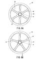
Fig. 6 shows the framework of the valve body shown inFig. 3 , in whichFig. 6A is a front view of the valve body framework having six spoke portions, andFig. 6B is also a front view of the valve body framework having five spoke portions; -
Fig. 7 is an exploded perspective view showing an intake valve of an internal combustion engine according to a second embodiment of the present invention; -
Fig. 8 is a front view showing a framework of the valve body in an intake valve of an internal combustion engine according to a third embodiment of the present invention; and -
Fig. 9 is a perspective view showing a framework of the valve body and a valve stem in an intake valve of an internal combustion engine according to a fourth embodiment of the present invention. - Embodiments of the present invention will be explained below with reference to the accompanying drawings. It should be noted that the present invention is not limited to these embodiments.
-
Fig. 1 is a cross-sectional view showing a valve train mechanism of an engine to which an intake valve of an internal combustion engine according to a first embodiment of the present invention is applied - The
engine 10 shown inFig. 1 is, for example, an engine mounted in a motorcycle having acylinder head 11 and acylinder head cover 12 in which a DOHC-type (double-overhead-camshaft type)valve train mechanism 14 is disposed. - As shown in
Fig. 1 , thecylinder head 11 of theengine 10 includes acombustion chamber 15 formed between thecylinder head 11 and acylinder block 13, twointake ports 16 communicated with thecombustion chamber 15, and twoexhaust ports 17 communicated with thecombustion chamber 15. Theintake port 16 and theexhaust port 17 includevalve sheets combustion chamber 15. Thevalve train mechanism 14 opens and closes the twointake valves 20 provided in theintake ports 16 and the twoexhaust valves 21 provided in theexhaust ports 17. - The
intake valves 20 open and close theintake ports 16. Theintake valve 20 includes avalve body 22 having a substantially circular umbrella-like shape (i.e., ring-shaped outer configuration) and avalve stem 23 extending toward substantially upward from the center of thevalve body 22. Thecylinder head 11 includes astem guide 24 into which thevalve stem 23 is slidably inserted. - The
exhaust valves 21 open and close theexhaust ports 17. Theexhaust valve 21 includes avalve body 25 having an umbrella-like shape and avalve stem 26 extending toward substantially upward from the center of thevalve body 25. Thecylinder head 11 includes astem guide 27 into which avalve stem 26 is slidably inserted. As viewed from a side of thecylinder head 11, theintake valve 20 and theexhaust valve 21 are disposed so that thevalve stem 23 and thevalve stem 26 provide an approximately V-shape. - The
valve gears 14 include anintake camshaft 28 rotatably pivoted by thecylinder head 11, twointake cams 29 provided on theintake camshaft 28, anintake tappet 30 lifting theintake valves 20 along cam profiles of theintake cams 29, and anintake valve spring 31 urging theintake valves 20 in a direction where theintake valves 20 are closed. - Furthermore, the
valve train mechanism 14 include anexhaust camshaft 32 rotatably pivoted by thecylinder head 11, twoexhaust cams 33 provided on theexhaust camshaft 32, anexhaust tappet 34 lifting theexhaust valves 21 along cam profiles of theexhaust cams 33, and anexhaust valve spring 35 urging theexhaust valves 21 in a direction where theexhaust valves 21 are closed. - The
intake camshaft 28 is located above theintake valves 20 and is rotatably pivoted by thecylinder head 11 and thehead cover 12. The axial center of theintake camshaft 28 is arranged approximately on an extension of thevalve stem 23 of theintake valves 20. Theintake cams 29 are integrated with theintake camshaft 28. Theintake cams 29 are provided at appropriate positions suitable for lifting theintake valves 20. Theintake tappet 30 is interposed between theintake valves 20 and theintake cams 29 so as to convert the rotational movement of theintake cams 29 into the reciprocal movement of theintake valves 20. - The
intake valve spring 31 is interposed between aspring retainer 36 provided at an upper end of thevalve stem 23 and a spring sheet 37 engaged loosely with thestem guide 24. Theintake valve spring 31 urges theintake valves 20 via thespring retainer 36 in the direction for closing theintake valves 20. Thevalve body 22 of theintake valve 20 is pressed by thevalve sheet 18 due to the urging force of theintake valve spring 31 to thereby close theintake ports 16. - The
exhaust camshaft 32 is positioned above theexhaust valves 21 and is rotatably pivoted by thecylinder head 11 and thehead cover 12. The axial center of theexhaust camshaft 32 is arranged approximately on an extension of thevalve stem 26 of theexhaust valves 21. Theintake camshaft 28 and theexhaust camshaft 32 are positioned so that the axes thereof substantially parallel to each other. - The
exhaust cams 33 are integrated with theexhaust camshaft 32. Theexhaust cams 33 are provided at appropriate positions suitable for lifting theexhaust valves 21. Theexhaust tappet 34 is interposed between theexhaust valves 21 and theexhaust cams 33 to thereby convert the rotational movement of theexhaust cams 33 into the reciprocal movement of theexhaust valves 21. - The
exhaust valve spring 35 is interposed between aspring retainer 38 provided at an upper end of thevalve stem 26 and aspring sheet 39 engaged loosely with thestem guide 27. Theexhaust valve spring 35 urges theexhaust valves 21 via thespring retainer 38 in the direction for closing theexhaust valves 21. Thevalve body 25 of theexhaust valve 21 is pressed by thevalve sheet 19 due to the urging force of theexhaust valve spring 35 so as to close theexhaust ports 17. - The
valve train mechanism 14 rotates theintake camshaft 28 and theintake cams 29 integrally so as to open and close theintake valves 20 through theintake tappet 30. Thevalve train mechanism 14 also rotates theexhaust camshaft 32 and theexhaust cams 33 integrally so as to open and close theexhaust valves 21 through theexhaust tappet 34. - As shown in
Figs. 2 and3 , theintake valve 20 serving as described above includes avalve stem 23 extending from the center of thevalve body 22. Thevalve body 22 includes a valve body framework (portion) 40 and a valve bodythick portion 45 on an inside of thevalve body framework 40. - In the first embodiment, the
valve stem 23 is integrated with acentral portion 41 of the valvebody framework portion 40. - The valve
body framework portion 40 includes a plurality ofspoke portions 42 radially extended from thecentral portion 41 of theframework portion 40 and anannular ring portion 43 connected to an outer end of each spokeportion 42. Thering portion 43 constitutes to an outer peripheral portion of theframework 40 of thevalve body 22. - As shown in
Figs. 4 and 5 , thering portion 43 is exposed from the valve bodythick portion 45 to serve as a valve sheet contact portion contacting thevalve sheet 18 of the cylinder head 11 (Fig. 1 ). As shown inFig. 6 , although the number of thespoke portions 42 may be six or five, the strength of theframework portion 40 varies depending on the number of thespoke portions 42 and their section modulus. - As shown in
Figs. 2 and3 , thevalve body framework 40 of thevalve body 22 and thevalve stem 23 in theintake valve 20 are integrally formed by a forging process using iron material (for example, SUH3 and SUH11 prescribed by Japanese Industrial Standard (JIS)). On the other hand, the valve bodythick portion 45 of thevalve body 22 is made of aluminum alloy, especially AC9B having high strength at an elevated temperature and a low coefficient of thermal expansion. As shown inFigs. 4 and 5 , the valve bodythick portion 45 is formed each on the front surface and on the rear surface of the valvebody framework portion 40 and is formed by a casting process so as to wrap theframework portion 40 from the front surface side and the rear surface side thereof. - Since the
central portion 41, thespoke portions 42 and thering portion 43 of theframework 40 of thevalve body 22, and, and thevalve stem 23 thereof are made of iron material, theintake valve 20 can provides necessary strength, and furthermore, the abrasion resistance of thering portion 43 serving as the valve sheet contact portion may be maintained. Moreover, since the valve bodythick portions 45 provided on the front surface and the rear surface of the valvebody framework portion 40 are made of aluminum alloy, the combustion pressure in the combustion chamber 15 (Fig. 1 ) is sealed by the valve bodythick portion 45 on the front surface side, and the intake air flowing in theintake port 16 is straightened (rectified) by the rear surface side of the valve bodythick portion 45. - Since the valve body
thick portion 45 embraces thecentral portion 41 and thespoke portions 42 of the bodyvalve framework portion 40, thespoke portions 42 may be made thinner than thering portion 43 exposed from the valve bodythick portion 45. In addition, since the valve bodythick portion 45 rectifies the flow of the intake air, a curvature radius R1 of thespoke portion 42 on the rear surface side is made larger than a curvature radius R2 of the valve bodythick portion 45 on the rear surface side to thereby avoid the concentration of stress to be generated on thecentral portion 41 of the valvebody framework portion 40. - As shown in
Fig. 5 , thecentral portion 41 of theframework portion 40 has arecess 44 formed in the front surface side front on the axial central portion (axis O) of theintake valve 20. Therecess 44 serves as a process center when the valvebody framework portion 40 is formed by the forging process and then the grinding process. By grinding the valvebody framework portion 40 by utilizing therecess 44 as the process center, the valvebody framework portion 40 can be formed by the forging process without being offset and with the total weight balance being stably maintained as well as suppressing in the dispersion of the strength. - As mentioned above, according to the first embodiment of the present invention, the following advantageous effects (1) to (6) will be obtainable.
- (1) Since the
valve body 22 of theintake valve 20 includes theframework portion 40 made of the iron material and thethick portion 45 made of the aluminum alloy, the weight of theintake valve 20 can be reduced as compared in a case where the valve body is made of only iron material. In addition, the manufacturing cost can be reduced as compared with the valve body made of titanium alloy.
Furthermore, the heat of theintake valve 20 can be favorably transferred by using the aluminum alloy, and by reducing the weight of theintake valve 20, the spring load of the intake valve spring 31 (Fig. 1 ) can be set to a low value. Thus, the contact pressure between theintake valve 20 and theintake cam 29 is reduced, and accordingly, the mechanical loss of thevalve train mechanism 14 can be reduced. - (2) Since the
valve stem 23 of theintake valve 20 is made of the iron material, the diameter of thevalve stem 23 can be reduced to thereby reduce the intake resistance thereof, and the durability of thestem end portion 23A of thevalve stem 23 can be improved. In addition, by improving the durability of thestem end portion 23A, an expensive surface treatment such as surface coating and fine shot peening by using DLC (diamond-like carbon) on thestem end portion 23A, or fixing treatment of dissimilar metal as disclosed in Patent Document 1 is not required, thus effectively reducing the manufacturing cost of theintake valve 20. - (3) Since the valve body
thick portion 45 is provided on the front surface side and rear surface side of theframework portion 40 of thevalve body 22 of theintake valve 20, theintake valve 20 can provide favorable heat conductivity.
Furthermore, since the valve bodythick portion 45 is formed by casting process so as to wrap around (embrace) the valvebody framework portion 40 from the front surface side and the rear surface side, the valve bodythick portion 45 can be prevented from dropping out even if thethick portion 45 is peeled off from the valvebody framework portion 40. Therefore, the sealing property of the combustion pressure is reduced by theintake valve 20 prior to the dropout of the valve bodythick portion 45. Thus, the damage of theengine 10 due to the dropout can be preliminarily prevented by exchanging theintake valve 20. - (4) Since the valve
body framework portion 40 of thevalve body 22 in theintake valve 20 includes the plurality ofspoke portions 42 radially extending from thecentral portion 41 and thering portion 43 connected to the outer ends of thespoke portions 42, the weight of theintake valve 20 can be reduced while ensuring its strength. - (5) Since the curvature radius R1 of the
spoke portion 42 of the valvebody framework portion 40 on the rear surface side is larger than the curvature radius R2 of the valve bodythick portion 45 on the rear surface side in thevalve body 22 of theintake valve 20, the concentration of stress on thecentral portion 41 of the valvebody framework portion 40 can be avoided. Consequently, the valvebody framework portion 40 can be thinned, and hence, the weight of theintake valve 20 can be reduced. - (6) Since the
ring portion 43 of the valvebody framework portion 40 made of the iron material serves as the valve sheet contact portion in thevalve body 22 of theintake valve 20, the abrasion resistance of the valve sheet contact portion can be improved. -
Fig. 7 is an exploded perspective view showing an intake valve of an internal combustion engine according to a second embodiment of the present invention. In the second embodiment, portions or members identical to those in the first embodiment are denoted by identical reference numerals and explanation thereof is simplified or omitted herein. - In a
valve body 50 of theintake valve 20 according to the second embodiment, the valvebody framework portion 40 is constructed separately from thevalve stem 23. After the valvebody framework portion 40 is welded or like to thevalve stem 23, the valve bodythick portion 45 is formed on the valvebody framework portion 40 by casting, thereby providing theintake valve 20. The valve stem 23 may formed to have a hollow body structure which can be filled with sodium having favorable thermal conductivity. Since thevalve body 50 of theintake valve 20 is constructed with the individually formedvalve stem 23 and valvebody framework portion 40, the productivity of theintake valve 20 can be improved. -
Fig. 8 is a front view showing a valve body framework portion of a valve body in an intake valve of an internal combustion engine according to a third embodiment of the present invention. In the third embodiment, portions or members identical to those in the first embodiment are denoted by identical reference numerals and explanation thereof is simplified or omitted herein. - In a valve
body framework portion 55 of thevalve body 22 of theintake valve 20 according to the third embodiment, thecentral portion 41 and thering portion 43 are connected by a plate-shaped portion ormember 56. A plurality of throughholes 57 are formed so as to penetrate theplate portion 56 from the front surface side to the rear surface side. The valve bodythick portions 45, not shown inFig. 8 , provided on the front surface and the rear surface of the valvebody framework portion 55 are connected by the throughholes 57, so that the dropout of the valve bodythick portion 45 can be reliably prevented. -
Fig. 9 is a perspective view showing a valve body framework portion of a valve body and a valve stem in an intake valve of an internal combustion engine according to a fourth embodiment of the present invention. In the fourth embodiment, portions or members identical to those in the first embodiment are denoted by identical reference numerals and explanation thereof is simplified or omitted herein. - In a valve
body framework portion 60 of thevalve body 22 of theintake valve 20 according to the fourth embodiment, thecentral portion 41 does not extend to the front surface side, and hence, any recess such as that 44 inFig. 5 , serving as the process center during the grinding operation, is not formed to thecentral portion 41. In the valvebody framework portion 60 according to the fourth embodiment, thevalve stem 23 is ground while thering portion 43 is held by a chuck of a grinding machine after the forging process. Then, thering portion 43 is ground while thevalve stem 23 is held by the chuck. Since thecentral portion 41 of the valvebody framework portion 60 does not extend to the front surface side in the present embodiment, the weight of theintake valve 20 can be further reduced. - It is to be noted that the present invention is not limited to the embodiments described above, and many other changes, alternations and modifications may be made without departing from the scopes of the appended claims.
- For example, in the described embodiments, although it is disclosed that the
valve body 22 of theintake valve 20 is produced by casting the valve body thick portion 45 (for example, AC9B (prescribed by JIS) into the valvebody framework portion 40, aluminum alloy corresponding to AC9B may be used for the valve bodythick portion 45, which is then caulked integrally with the front and rear surfaces of theframework portion 40 to thereby form thevalve body 22.
Claims (9)
- An intake valve of an internal combustion engine, comprising:a valve body; anda valve stem extending from a central portion of the valve body,wherein the valve body includes a valve body framework portion and a valve body thick portion provided on an outer side of the valve body framework portion, and the valve body framework portion and the valve stem are made of iron material and the valve body thick portion is made of aluminum alloy.
- The intake valve of the internal combustion engine according to claim 1, wherein the valve body thick portion is provided on a front surface side and a rear surface side of the valve body framework portion.
- The intake valve of the internal combustion engine according to claim 2, wherein the valve body is formed by casting process so that the valve body thick portion wraps around the valve body framework portion.
- The intake valve of the internal combustion engine according to claim 2, wherein the valve body framework portion of the valve body includes a plurality of through holes penetrating the valve body from the front surface side to the rear surface side.
- The intake valve of the internal combustion engine according to claim 2, wherein the valve body framework portion of the valve body includes a plurality of spoke portions and an annular ring portion, the spoke portion extending from the central portion of the valve body and connected to the annular ring portion at the extending outer ends thereof.
- The intake valve of the internal combustion engine according to claim 1, wherein the valve body framework portion of the valve body is constructed integrally with the valve stem.
- The intake valve of the internal combustion engine according to claim 1, wherein the valve body framework portion of the valve body is constructed separately from the valve stem.
- The intake valve of the internal combustion engine according to claim 1, wherein a curvature radius of the valve body framework portion on a rear surface side of the valve body is larger than a curvature radius of the valve body thick portion on a rear surface side thereof.
- The intake valve of the internal combustion engine according to claim 1, wherein an outer periphery of the valve body framework portion of the valve body is exposed from the valve body thick portion as a valve sheet contact portion contacting a valve sheet.
Applications Claiming Priority (1)
| Application Number | Priority Date | Filing Date | Title |
|---|---|---|---|
| JP2011021919A JP5625967B2 (en) | 2011-02-03 | 2011-02-03 | Intake valve for internal combustion engine |
Publications (2)
| Publication Number | Publication Date |
|---|---|
| EP2484482A1 true EP2484482A1 (en) | 2012-08-08 |
| EP2484482B1 EP2484482B1 (en) | 2015-06-03 |
Family
ID=45524389
Family Applications (1)
| Application Number | Title | Priority Date | Filing Date |
|---|---|---|---|
| EP12152362.5A Active EP2484482B1 (en) | 2011-02-03 | 2012-01-25 | Intake valve of internal combustion engine |
Country Status (4)
| Country | Link |
|---|---|
| US (1) | US8893680B2 (en) |
| EP (1) | EP2484482B1 (en) |
| JP (1) | JP5625967B2 (en) |
| ES (1) | ES2543639T3 (en) |
Families Citing this family (5)
| Publication number | Priority date | Publication date | Assignee | Title |
|---|---|---|---|---|
| JP5964134B2 (en) * | 2012-05-23 | 2016-08-03 | 愛三工業株式会社 | Engine valve for intake |
| US9995187B2 (en) | 2016-01-26 | 2018-06-12 | Honda Motor Co., Ltd. | Intake valve apparatus for use with a combustion engine and methods of use and manufacture thereof |
| US10760455B2 (en) * | 2016-12-20 | 2020-09-01 | Caterpillar Inc. | Poppet valve for an internal combustion engine |
| JP6597663B2 (en) | 2017-02-08 | 2019-10-30 | トヨタ自動車株式会社 | Engine valve |
| DE102023200287A1 (en) * | 2023-01-16 | 2024-08-01 | Mahle International Gmbh | Valve for an internal combustion engine and manufacturing method |
Citations (12)
| Publication number | Priority date | Publication date | Assignee | Title |
|---|---|---|---|---|
| GB123416A (en) * | 1918-02-28 | 1919-02-27 | John Buchanan | Composite Valve for all Classes of Internal Combustion Engines. |
| US1557022A (en) * | 1922-11-03 | 1925-10-13 | Aeromarine Plane & Motor Compa | Valve and method of making same |
| US2162063A (en) * | 1936-02-29 | 1939-06-13 | Thompson Prod Inc | Valve and a method of making the same |
| JPS5726216A (en) * | 1980-07-24 | 1982-02-12 | Kobe Steel Ltd | Production of exhaust valve for internal combustion engine |
| JPS61202606U (en) | 1985-06-10 | 1986-12-19 | ||
| EP1188975A2 (en) * | 2000-09-19 | 2002-03-20 | Fuji Oozx Inc. | Poppet valve and a method of manufacturing the same |
| DE10204122C1 (en) * | 2002-02-01 | 2003-05-08 | Daimler Chrysler Ag | Valve, for reciprocating piston machine, comprises a valve disk having an undercut expansion axially protruding over an enlarged area of a valve shaft to axially clamp the enlarged area and produce a form-locking connection |
| WO2003050395A1 (en) * | 2001-12-12 | 2003-06-19 | Daimlerchrysler Ag | Multi-piece valve for internal combustion piston engines |
| JP2003343219A (en) * | 2002-05-27 | 2003-12-03 | Isao Shirayanagi | Intake and exhaust valves for engine |
| WO2003100223A1 (en) * | 2002-05-28 | 2003-12-04 | Daimlerchrysler Ag | Method for producing a built valve having a hollow shank for reciprocating piston engines |
| JP2004308607A (en) * | 2003-04-09 | 2004-11-04 | Isao Shirayanagi | Engine valve and method for manufacturing the same |
| DE10354077A1 (en) * | 2003-11-19 | 2005-06-02 | Daimlerchrysler Ag | lightweight valve |
Family Cites Families (2)
| Publication number | Priority date | Publication date | Assignee | Title |
|---|---|---|---|---|
| JPS61202606A (en) | 1985-03-04 | 1986-09-08 | 株式会社クボタ | agricultural tractor |
| JP2004150349A (en) * | 2002-10-30 | 2004-05-27 | Isao Shirayanagi | Cooling structure of engine valve |
-
2011
- 2011-02-03 JP JP2011021919A patent/JP5625967B2/en active Active
-
2012
- 2012-01-25 US US13/358,048 patent/US8893680B2/en active Active
- 2012-01-25 EP EP12152362.5A patent/EP2484482B1/en active Active
- 2012-01-25 ES ES12152362.5T patent/ES2543639T3/en active Active
Patent Citations (12)
| Publication number | Priority date | Publication date | Assignee | Title |
|---|---|---|---|---|
| GB123416A (en) * | 1918-02-28 | 1919-02-27 | John Buchanan | Composite Valve for all Classes of Internal Combustion Engines. |
| US1557022A (en) * | 1922-11-03 | 1925-10-13 | Aeromarine Plane & Motor Compa | Valve and method of making same |
| US2162063A (en) * | 1936-02-29 | 1939-06-13 | Thompson Prod Inc | Valve and a method of making the same |
| JPS5726216A (en) * | 1980-07-24 | 1982-02-12 | Kobe Steel Ltd | Production of exhaust valve for internal combustion engine |
| JPS61202606U (en) | 1985-06-10 | 1986-12-19 | ||
| EP1188975A2 (en) * | 2000-09-19 | 2002-03-20 | Fuji Oozx Inc. | Poppet valve and a method of manufacturing the same |
| WO2003050395A1 (en) * | 2001-12-12 | 2003-06-19 | Daimlerchrysler Ag | Multi-piece valve for internal combustion piston engines |
| DE10204122C1 (en) * | 2002-02-01 | 2003-05-08 | Daimler Chrysler Ag | Valve, for reciprocating piston machine, comprises a valve disk having an undercut expansion axially protruding over an enlarged area of a valve shaft to axially clamp the enlarged area and produce a form-locking connection |
| JP2003343219A (en) * | 2002-05-27 | 2003-12-03 | Isao Shirayanagi | Intake and exhaust valves for engine |
| WO2003100223A1 (en) * | 2002-05-28 | 2003-12-04 | Daimlerchrysler Ag | Method for producing a built valve having a hollow shank for reciprocating piston engines |
| JP2004308607A (en) * | 2003-04-09 | 2004-11-04 | Isao Shirayanagi | Engine valve and method for manufacturing the same |
| DE10354077A1 (en) * | 2003-11-19 | 2005-06-02 | Daimlerchrysler Ag | lightweight valve |
Also Published As
| Publication number | Publication date |
|---|---|
| JP2012162999A (en) | 2012-08-30 |
| ES2543639T3 (en) | 2015-08-20 |
| US8893680B2 (en) | 2014-11-25 |
| US20120199092A1 (en) | 2012-08-09 |
| EP2484482B1 (en) | 2015-06-03 |
| JP5625967B2 (en) | 2014-11-19 |
Similar Documents
| Publication | Publication Date | Title |
|---|---|---|
| US8893680B2 (en) | Intake valve of internal combustion engine | |
| US7854215B2 (en) | Valve train with overload features | |
| EP2625393B1 (en) | Positive control (desmodromic) valve systems for internal combustion engines | |
| US10590814B2 (en) | Cylinder deactivation deactivating roller finger follower having improved packaging | |
| JP5311918B2 (en) | Spring retainer and spring system | |
| JP6147699B2 (en) | Intake valve and intake / exhaust device having the same | |
| JP5964134B2 (en) | Engine valve for intake | |
| US8555841B2 (en) | Coupling plate between valves | |
| JP2019509423A (en) | Engine valve lifter with anti-rotation plug | |
| JP2017190759A (en) | Hollow engine valve and stem cap | |
| US20190211752A1 (en) | Plate and method for manufacturing plate | |
| EP3156618B1 (en) | Engine | |
| US20110162609A1 (en) | Vehicle engine | |
| US5269268A (en) | Tappet in an internal combustion engine and method of manufacturing the same | |
| US20130291813A1 (en) | Drive Cam and Valve Operating System in Engine | |
| EP2767680A1 (en) | Camshaft support structure | |
| JP5556605B2 (en) | Variable valve operating device for internal combustion engine | |
| US7308760B2 (en) | Method of making a valve lifter | |
| JP4283208B2 (en) | valve | |
| JP6327018B2 (en) | Engine valve structure | |
| EP0618350B1 (en) | Tappet in an internal combustion engine and method of manufacturing the same | |
| JP4190210B2 (en) | Engine intake and exhaust valves | |
| JP2761508B2 (en) | Tappet for internal combustion engine and manufacturing method thereof | |
| JP2008133749A (en) | Camshaft bearing structure and bearing method | |
| JP2007056800A (en) | Valve mechanism of internal combustion engine |
Legal Events
| Date | Code | Title | Description |
|---|---|---|---|
| PUAI | Public reference made under article 153(3) epc to a published international application that has entered the european phase |
Free format text: ORIGINAL CODE: 0009012 |
|
| AK | Designated contracting states |
Kind code of ref document: A1 Designated state(s): AL AT BE BG CH CY CZ DE DK EE ES FI FR GB GR HR HU IE IS IT LI LT LU LV MC MK MT NL NO PL PT RO RS SE SI SK SM TR |
|
| AX | Request for extension of the european patent |
Extension state: BA ME |
|
| 17P | Request for examination filed |
Effective date: 20121205 |
|
| 17Q | First examination report despatched |
Effective date: 20130212 |
|
| GRAP | Despatch of communication of intention to grant a patent |
Free format text: ORIGINAL CODE: EPIDOSNIGR1 |
|
| INTG | Intention to grant announced |
Effective date: 20150123 |
|
| GRAS | Grant fee paid |
Free format text: ORIGINAL CODE: EPIDOSNIGR3 |
|
| GRAA | (expected) grant |
Free format text: ORIGINAL CODE: 0009210 |
|
| AK | Designated contracting states |
Kind code of ref document: B1 Designated state(s): AL AT BE BG CH CY CZ DE DK EE ES FI FR GB GR HR HU IE IS IT LI LT LU LV MC MK MT NL NO PL PT RO RS SE SI SK SM TR |
|
| REG | Reference to a national code |
Ref country code: GB Ref legal event code: FG4D |
|
| REG | Reference to a national code |
Ref country code: CH Ref legal event code: EP |
|
| REG | Reference to a national code |
Ref country code: AT Ref legal event code: REF Ref document number: 729663 Country of ref document: AT Kind code of ref document: T Effective date: 20150715 Ref country code: IE Ref legal event code: FG4D |
|
| REG | Reference to a national code |
Ref country code: DE Ref legal event code: R096 Ref document number: 602012007662 Country of ref document: DE |
|
| REG | Reference to a national code |
Ref country code: ES Ref legal event code: FG2A Ref document number: 2543639 Country of ref document: ES Kind code of ref document: T3 Effective date: 20150820 |
|
| REG | Reference to a national code |
Ref country code: AT Ref legal event code: MK05 Ref document number: 729663 Country of ref document: AT Kind code of ref document: T Effective date: 20150603 |
|
| PG25 | Lapsed in a contracting state [announced via postgrant information from national office to epo] |
Ref country code: NO Free format text: LAPSE BECAUSE OF FAILURE TO SUBMIT A TRANSLATION OF THE DESCRIPTION OR TO PAY THE FEE WITHIN THE PRESCRIBED TIME-LIMIT Effective date: 20150903 Ref country code: LT Free format text: LAPSE BECAUSE OF FAILURE TO SUBMIT A TRANSLATION OF THE DESCRIPTION OR TO PAY THE FEE WITHIN THE PRESCRIBED TIME-LIMIT Effective date: 20150603 Ref country code: HR Free format text: LAPSE BECAUSE OF FAILURE TO SUBMIT A TRANSLATION OF THE DESCRIPTION OR TO PAY THE FEE WITHIN THE PRESCRIBED TIME-LIMIT Effective date: 20150603 Ref country code: FI Free format text: LAPSE BECAUSE OF FAILURE TO SUBMIT A TRANSLATION OF THE DESCRIPTION OR TO PAY THE FEE WITHIN THE PRESCRIBED TIME-LIMIT Effective date: 20150603 |
|
| REG | Reference to a national code |
Ref country code: NL Ref legal event code: MP Effective date: 20150603 |
|
| REG | Reference to a national code |
Ref country code: LT Ref legal event code: MG4D |
|
| PG25 | Lapsed in a contracting state [announced via postgrant information from national office to epo] |
Ref country code: AT Free format text: LAPSE BECAUSE OF FAILURE TO SUBMIT A TRANSLATION OF THE DESCRIPTION OR TO PAY THE FEE WITHIN THE PRESCRIBED TIME-LIMIT Effective date: 20150603 Ref country code: BG Free format text: LAPSE BECAUSE OF FAILURE TO SUBMIT A TRANSLATION OF THE DESCRIPTION OR TO PAY THE FEE WITHIN THE PRESCRIBED TIME-LIMIT Effective date: 20150903 Ref country code: RS Free format text: LAPSE BECAUSE OF FAILURE TO SUBMIT A TRANSLATION OF THE DESCRIPTION OR TO PAY THE FEE WITHIN THE PRESCRIBED TIME-LIMIT Effective date: 20150603 Ref country code: LV Free format text: LAPSE BECAUSE OF FAILURE TO SUBMIT A TRANSLATION OF THE DESCRIPTION OR TO PAY THE FEE WITHIN THE PRESCRIBED TIME-LIMIT Effective date: 20150603 Ref country code: GR Free format text: LAPSE BECAUSE OF FAILURE TO SUBMIT A TRANSLATION OF THE DESCRIPTION OR TO PAY THE FEE WITHIN THE PRESCRIBED TIME-LIMIT Effective date: 20150904 |
|
| PG25 | Lapsed in a contracting state [announced via postgrant information from national office to epo] |
Ref country code: EE Free format text: LAPSE BECAUSE OF FAILURE TO SUBMIT A TRANSLATION OF THE DESCRIPTION OR TO PAY THE FEE WITHIN THE PRESCRIBED TIME-LIMIT Effective date: 20150603 |
|
| PG25 | Lapsed in a contracting state [announced via postgrant information from national office to epo] |
Ref country code: SK Free format text: LAPSE BECAUSE OF FAILURE TO SUBMIT A TRANSLATION OF THE DESCRIPTION OR TO PAY THE FEE WITHIN THE PRESCRIBED TIME-LIMIT Effective date: 20150603 Ref country code: RO Free format text: LAPSE BECAUSE OF NON-PAYMENT OF DUE FEES Effective date: 20150603 Ref country code: PL Free format text: LAPSE BECAUSE OF FAILURE TO SUBMIT A TRANSLATION OF THE DESCRIPTION OR TO PAY THE FEE WITHIN THE PRESCRIBED TIME-LIMIT Effective date: 20150603 Ref country code: IS Free format text: LAPSE BECAUSE OF FAILURE TO SUBMIT A TRANSLATION OF THE DESCRIPTION OR TO PAY THE FEE WITHIN THE PRESCRIBED TIME-LIMIT Effective date: 20151003 Ref country code: PT Free format text: LAPSE BECAUSE OF FAILURE TO SUBMIT A TRANSLATION OF THE DESCRIPTION OR TO PAY THE FEE WITHIN THE PRESCRIBED TIME-LIMIT Effective date: 20151006 Ref country code: CZ Free format text: LAPSE BECAUSE OF FAILURE TO SUBMIT A TRANSLATION OF THE DESCRIPTION OR TO PAY THE FEE WITHIN THE PRESCRIBED TIME-LIMIT Effective date: 20150603 |
|
| REG | Reference to a national code |
Ref country code: DE Ref legal event code: R097 Ref document number: 602012007662 Country of ref document: DE |
|
| PLBE | No opposition filed within time limit |
Free format text: ORIGINAL CODE: 0009261 |
|
| STAA | Information on the status of an ep patent application or granted ep patent |
Free format text: STATUS: NO OPPOSITION FILED WITHIN TIME LIMIT |
|
| PG25 | Lapsed in a contracting state [announced via postgrant information from national office to epo] |
Ref country code: DK Free format text: LAPSE BECAUSE OF FAILURE TO SUBMIT A TRANSLATION OF THE DESCRIPTION OR TO PAY THE FEE WITHIN THE PRESCRIBED TIME-LIMIT Effective date: 20150603 |
|
| 26N | No opposition filed |
Effective date: 20160304 |
|
| PG25 | Lapsed in a contracting state [announced via postgrant information from national office to epo] |
Ref country code: BE Free format text: LAPSE BECAUSE OF NON-PAYMENT OF DUE FEES Effective date: 20160131 Ref country code: SI Free format text: LAPSE BECAUSE OF FAILURE TO SUBMIT A TRANSLATION OF THE DESCRIPTION OR TO PAY THE FEE WITHIN THE PRESCRIBED TIME-LIMIT Effective date: 20150603 |
|
| REG | Reference to a national code |
Ref country code: DE Ref legal event code: R119 Ref document number: 602012007662 Country of ref document: DE |
|
| PG25 | Lapsed in a contracting state [announced via postgrant information from national office to epo] |
Ref country code: LU Free format text: LAPSE BECAUSE OF FAILURE TO SUBMIT A TRANSLATION OF THE DESCRIPTION OR TO PAY THE FEE WITHIN THE PRESCRIBED TIME-LIMIT Effective date: 20160125 |
|
| REG | Reference to a national code |
Ref country code: CH Ref legal event code: PL |
|
| GBPC | Gb: european patent ceased through non-payment of renewal fee |
Effective date: 20160125 |
|
| PG25 | Lapsed in a contracting state [announced via postgrant information from national office to epo] |
Ref country code: MC Free format text: LAPSE BECAUSE OF FAILURE TO SUBMIT A TRANSLATION OF THE DESCRIPTION OR TO PAY THE FEE WITHIN THE PRESCRIBED TIME-LIMIT Effective date: 20150603 |
|
| REG | Reference to a national code |
Ref country code: FR Ref legal event code: ST Effective date: 20160930 |
|
| PG25 | Lapsed in a contracting state [announced via postgrant information from national office to epo] |
Ref country code: CH Free format text: LAPSE BECAUSE OF NON-PAYMENT OF DUE FEES Effective date: 20160131 Ref country code: LI Free format text: LAPSE BECAUSE OF NON-PAYMENT OF DUE FEES Effective date: 20160131 Ref country code: GB Free format text: LAPSE BECAUSE OF NON-PAYMENT OF DUE FEES Effective date: 20160125 Ref country code: DE Free format text: LAPSE BECAUSE OF NON-PAYMENT OF DUE FEES Effective date: 20160802 |
|
| REG | Reference to a national code |
Ref country code: IE Ref legal event code: MM4A |
|
| PG25 | Lapsed in a contracting state [announced via postgrant information from national office to epo] |
Ref country code: FR Free format text: LAPSE BECAUSE OF NON-PAYMENT OF DUE FEES Effective date: 20160201 |
|
| PG25 | Lapsed in a contracting state [announced via postgrant information from national office to epo] |
Ref country code: BE Free format text: LAPSE BECAUSE OF FAILURE TO SUBMIT A TRANSLATION OF THE DESCRIPTION OR TO PAY THE FEE WITHIN THE PRESCRIBED TIME-LIMIT Effective date: 20150603 |
|
| PG25 | Lapsed in a contracting state [announced via postgrant information from national office to epo] |
Ref country code: IE Free format text: LAPSE BECAUSE OF NON-PAYMENT OF DUE FEES Effective date: 20160125 |
|
| PG25 | Lapsed in a contracting state [announced via postgrant information from national office to epo] |
Ref country code: NL Free format text: LAPSE BECAUSE OF FAILURE TO SUBMIT A TRANSLATION OF THE DESCRIPTION OR TO PAY THE FEE WITHIN THE PRESCRIBED TIME-LIMIT Effective date: 20150603 Ref country code: SE Free format text: LAPSE BECAUSE OF FAILURE TO SUBMIT A TRANSLATION OF THE DESCRIPTION OR TO PAY THE FEE WITHIN THE PRESCRIBED TIME-LIMIT Effective date: 20150603 |
|
| PG25 | Lapsed in a contracting state [announced via postgrant information from national office to epo] |
Ref country code: MT Free format text: LAPSE BECAUSE OF FAILURE TO SUBMIT A TRANSLATION OF THE DESCRIPTION OR TO PAY THE FEE WITHIN THE PRESCRIBED TIME-LIMIT Effective date: 20150603 |
|
| PG25 | Lapsed in a contracting state [announced via postgrant information from national office to epo] |
Ref country code: HU Free format text: LAPSE BECAUSE OF FAILURE TO SUBMIT A TRANSLATION OF THE DESCRIPTION OR TO PAY THE FEE WITHIN THE PRESCRIBED TIME-LIMIT; INVALID AB INITIO Effective date: 20120125 Ref country code: SM Free format text: LAPSE BECAUSE OF FAILURE TO SUBMIT A TRANSLATION OF THE DESCRIPTION OR TO PAY THE FEE WITHIN THE PRESCRIBED TIME-LIMIT Effective date: 20150603 Ref country code: CY Free format text: LAPSE BECAUSE OF FAILURE TO SUBMIT A TRANSLATION OF THE DESCRIPTION OR TO PAY THE FEE WITHIN THE PRESCRIBED TIME-LIMIT Effective date: 20150603 |
|
| PG25 | Lapsed in a contracting state [announced via postgrant information from national office to epo] |
Ref country code: TR Free format text: LAPSE BECAUSE OF FAILURE TO SUBMIT A TRANSLATION OF THE DESCRIPTION OR TO PAY THE FEE WITHIN THE PRESCRIBED TIME-LIMIT Effective date: 20150603 Ref country code: MK Free format text: LAPSE BECAUSE OF FAILURE TO SUBMIT A TRANSLATION OF THE DESCRIPTION OR TO PAY THE FEE WITHIN THE PRESCRIBED TIME-LIMIT Effective date: 20150603 Ref country code: MT Free format text: LAPSE BECAUSE OF FAILURE TO SUBMIT A TRANSLATION OF THE DESCRIPTION OR TO PAY THE FEE WITHIN THE PRESCRIBED TIME-LIMIT Effective date: 20160131 |
|
| PG25 | Lapsed in a contracting state [announced via postgrant information from national office to epo] |
Ref country code: AL Free format text: LAPSE BECAUSE OF FAILURE TO SUBMIT A TRANSLATION OF THE DESCRIPTION OR TO PAY THE FEE WITHIN THE PRESCRIBED TIME-LIMIT Effective date: 20150603 |
|
| PGFP | Annual fee paid to national office [announced via postgrant information from national office to epo] |
Ref country code: ES Payment date: 20260203 Year of fee payment: 15 |
|
| PGFP | Annual fee paid to national office [announced via postgrant information from national office to epo] |
Ref country code: IT Payment date: 20251219 Year of fee payment: 15 |