EP2484447A1 - Improved encoded microcarriers, assay system using them and method for performing an assay - Google Patents
Improved encoded microcarriers, assay system using them and method for performing an assay Download PDFInfo
- Publication number
- EP2484447A1 EP2484447A1 EP11000970A EP11000970A EP2484447A1 EP 2484447 A1 EP2484447 A1 EP 2484447A1 EP 11000970 A EP11000970 A EP 11000970A EP 11000970 A EP11000970 A EP 11000970A EP 2484447 A1 EP2484447 A1 EP 2484447A1
- Authority
- EP
- European Patent Office
- Prior art keywords
- encoded
- microcarrier
- detection surface
- flat plane
- encoded microcarrier
- Prior art date
- Legal status (The legal status is an assumption and is not a legal conclusion. Google has not performed a legal analysis and makes no representation as to the accuracy of the status listed.)
- Withdrawn
Links
Images


Classifications
-
- G—PHYSICS
- G01—MEASURING; TESTING
- G01N—INVESTIGATING OR ANALYSING MATERIALS BY DETERMINING THEIR CHEMICAL OR PHYSICAL PROPERTIES
- G01N21/00—Investigating or analysing materials by the use of optical means, i.e. using sub-millimetre waves, infrared, visible or ultraviolet light
- G01N21/62—Systems in which the material investigated is excited whereby it emits light or causes a change in wavelength of the incident light
- G01N21/63—Systems in which the material investigated is excited whereby it emits light or causes a change in wavelength of the incident light optically excited
- G01N21/64—Fluorescence; Phosphorescence
- G01N21/6486—Measuring fluorescence of biological material, e.g. DNA, RNA, cells
-
- B—PERFORMING OPERATIONS; TRANSPORTING
- B01—PHYSICAL OR CHEMICAL PROCESSES OR APPARATUS IN GENERAL
- B01L—CHEMICAL OR PHYSICAL LABORATORY APPARATUS FOR GENERAL USE
- B01L3/00—Containers or dishes for laboratory use, e.g. laboratory glassware; Droppers
-
- B—PERFORMING OPERATIONS; TRANSPORTING
- B01—PHYSICAL OR CHEMICAL PROCESSES OR APPARATUS IN GENERAL
- B01J—CHEMICAL OR PHYSICAL PROCESSES, e.g. CATALYSIS OR COLLOID CHEMISTRY; THEIR RELEVANT APPARATUS
- B01J19/00—Chemical, physical or physico-chemical processes in general; Their relevant apparatus
-
- B—PERFORMING OPERATIONS; TRANSPORTING
- B01—PHYSICAL OR CHEMICAL PROCESSES OR APPARATUS IN GENERAL
- B01L—CHEMICAL OR PHYSICAL LABORATORY APPARATUS FOR GENERAL USE
- B01L3/00—Containers or dishes for laboratory use, e.g. laboratory glassware; Droppers
- B01L3/50—Containers for the purpose of retaining a material to be analysed, e.g. test tubes
- B01L3/502—Containers for the purpose of retaining a material to be analysed, e.g. test tubes with fluid transport, e.g. in multi-compartment structures
- B01L3/5027—Containers for the purpose of retaining a material to be analysed, e.g. test tubes with fluid transport, e.g. in multi-compartment structures by integrated microfluidic structures, i.e. dimensions of channels and chambers are such that surface tension forces are important, e.g. lab-on-a-chip
- B01L3/502761—Containers for the purpose of retaining a material to be analysed, e.g. test tubes with fluid transport, e.g. in multi-compartment structures by integrated microfluidic structures, i.e. dimensions of channels and chambers are such that surface tension forces are important, e.g. lab-on-a-chip specially adapted for handling suspended solids or molecules independently from the bulk fluid flow, e.g. for trapping or sorting beads, for physically stretching molecules
-
- G—PHYSICS
- G01—MEASURING; TESTING
- G01N—INVESTIGATING OR ANALYSING MATERIALS BY DETERMINING THEIR CHEMICAL OR PHYSICAL PROPERTIES
- G01N33/00—Investigating or analysing materials by specific methods not covered by groups G01N1/00 - G01N31/00
- G01N33/48—Biological material, e.g. blood, urine; Haemocytometers
- G01N33/50—Chemical analysis of biological material, e.g. blood, urine; Testing involving biospecific ligand binding methods; Immunological testing
- G01N33/53—Immunoassay; Biospecific binding assay; Materials therefor
- G01N33/543—Immunoassay; Biospecific binding assay; Materials therefor with an insoluble carrier for immobilising immunochemicals
-
- G—PHYSICS
- G01—MEASURING; TESTING
- G01N—INVESTIGATING OR ANALYSING MATERIALS BY DETERMINING THEIR CHEMICAL OR PHYSICAL PROPERTIES
- G01N35/00—Automatic analysis not limited to methods or materials provided for in any single one of groups G01N1/00 - G01N33/00; Handling materials therefor
-
- B—PERFORMING OPERATIONS; TRANSPORTING
- B01—PHYSICAL OR CHEMICAL PROCESSES OR APPARATUS IN GENERAL
- B01J—CHEMICAL OR PHYSICAL PROCESSES, e.g. CATALYSIS OR COLLOID CHEMISTRY; THEIR RELEVANT APPARATUS
- B01J2219/00—Chemical, physical or physico-chemical processes in general; Their relevant apparatus
- B01J2219/00274—Sequential or parallel reactions; Apparatus and devices for combinatorial chemistry or for making arrays; Chemical library technology
- B01J2219/00277—Apparatus
- B01J2219/00457—Dispensing or evacuation of the solid phase support
- B01J2219/00459—Beads
-
- B—PERFORMING OPERATIONS; TRANSPORTING
- B01—PHYSICAL OR CHEMICAL PROCESSES OR APPARATUS IN GENERAL
- B01J—CHEMICAL OR PHYSICAL PROCESSES, e.g. CATALYSIS OR COLLOID CHEMISTRY; THEIR RELEVANT APPARATUS
- B01J2219/00—Chemical, physical or physico-chemical processes in general; Their relevant apparatus
- B01J2219/00274—Sequential or parallel reactions; Apparatus and devices for combinatorial chemistry or for making arrays; Chemical library technology
- B01J2219/00277—Apparatus
- B01J2219/00497—Features relating to the solid phase supports
- B01J2219/005—Beads
-
- B—PERFORMING OPERATIONS; TRANSPORTING
- B01—PHYSICAL OR CHEMICAL PROCESSES OR APPARATUS IN GENERAL
- B01J—CHEMICAL OR PHYSICAL PROCESSES, e.g. CATALYSIS OR COLLOID CHEMISTRY; THEIR RELEVANT APPARATUS
- B01J2219/00—Chemical, physical or physico-chemical processes in general; Their relevant apparatus
- B01J2219/00274—Sequential or parallel reactions; Apparatus and devices for combinatorial chemistry or for making arrays; Chemical library technology
- B01J2219/00277—Apparatus
- B01J2219/0054—Means for coding or tagging the apparatus or the reagents
- B01J2219/00554—Physical means
- B01J2219/00558—Cuts-out
-
- B—PERFORMING OPERATIONS; TRANSPORTING
- B01—PHYSICAL OR CHEMICAL PROCESSES OR APPARATUS IN GENERAL
- B01J—CHEMICAL OR PHYSICAL PROCESSES, e.g. CATALYSIS OR COLLOID CHEMISTRY; THEIR RELEVANT APPARATUS
- B01J2219/00—Chemical, physical or physico-chemical processes in general; Their relevant apparatus
- B01J2219/00274—Sequential or parallel reactions; Apparatus and devices for combinatorial chemistry or for making arrays; Chemical library technology
- B01J2219/00277—Apparatus
- B01J2219/0054—Means for coding or tagging the apparatus or the reagents
- B01J2219/00554—Physical means
- B01J2219/0056—Raised or sunken areas
-
- B—PERFORMING OPERATIONS; TRANSPORTING
- B01—PHYSICAL OR CHEMICAL PROCESSES OR APPARATUS IN GENERAL
- B01J—CHEMICAL OR PHYSICAL PROCESSES, e.g. CATALYSIS OR COLLOID CHEMISTRY; THEIR RELEVANT APPARATUS
- B01J2219/00—Chemical, physical or physico-chemical processes in general; Their relevant apparatus
- B01J2219/00274—Sequential or parallel reactions; Apparatus and devices for combinatorial chemistry or for making arrays; Chemical library technology
- B01J2219/00277—Apparatus
- B01J2219/0054—Means for coding or tagging the apparatus or the reagents
- B01J2219/00572—Chemical means
- B01J2219/00576—Chemical means fluorophore
-
- B—PERFORMING OPERATIONS; TRANSPORTING
- B01—PHYSICAL OR CHEMICAL PROCESSES OR APPARATUS IN GENERAL
- B01J—CHEMICAL OR PHYSICAL PROCESSES, e.g. CATALYSIS OR COLLOID CHEMISTRY; THEIR RELEVANT APPARATUS
- B01J2219/00—Chemical, physical or physico-chemical processes in general; Their relevant apparatus
- B01J2219/00274—Sequential or parallel reactions; Apparatus and devices for combinatorial chemistry or for making arrays; Chemical library technology
- B01J2219/00718—Type of compounds synthesised
- B01J2219/0072—Organic compounds
- B01J2219/00725—Peptides
-
- B—PERFORMING OPERATIONS; TRANSPORTING
- B01—PHYSICAL OR CHEMICAL PROCESSES OR APPARATUS IN GENERAL
- B01J—CHEMICAL OR PHYSICAL PROCESSES, e.g. CATALYSIS OR COLLOID CHEMISTRY; THEIR RELEVANT APPARATUS
- B01J2219/00—Chemical, physical or physico-chemical processes in general; Their relevant apparatus
- B01J2219/00274—Sequential or parallel reactions; Apparatus and devices for combinatorial chemistry or for making arrays; Chemical library technology
- B01J2219/00718—Type of compounds synthesised
- B01J2219/0072—Organic compounds
- B01J2219/0074—Biological products
-
- B—PERFORMING OPERATIONS; TRANSPORTING
- B01—PHYSICAL OR CHEMICAL PROCESSES OR APPARATUS IN GENERAL
- B01L—CHEMICAL OR PHYSICAL LABORATORY APPARATUS FOR GENERAL USE
- B01L2200/00—Solutions for specific problems relating to chemical or physical laboratory apparatus
- B01L2200/06—Fluid handling related problems
- B01L2200/0647—Handling flowable solids, e.g. microscopic beads, cells, particles
-
- B—PERFORMING OPERATIONS; TRANSPORTING
- B01—PHYSICAL OR CHEMICAL PROCESSES OR APPARATUS IN GENERAL
- B01L—CHEMICAL OR PHYSICAL LABORATORY APPARATUS FOR GENERAL USE
- B01L2300/00—Additional constructional details
- B01L2300/02—Identification, exchange or storage of information
- B01L2300/021—Identification, e.g. bar codes
-
- B—PERFORMING OPERATIONS; TRANSPORTING
- B01—PHYSICAL OR CHEMICAL PROCESSES OR APPARATUS IN GENERAL
- B01L—CHEMICAL OR PHYSICAL LABORATORY APPARATUS FOR GENERAL USE
- B01L2300/00—Additional constructional details
- B01L2300/08—Geometry, shape and general structure
- B01L2300/0832—Geometry, shape and general structure cylindrical, tube shaped
-
- G—PHYSICS
- G01—MEASURING; TESTING
- G01N—INVESTIGATING OR ANALYSING MATERIALS BY DETERMINING THEIR CHEMICAL OR PHYSICAL PROPERTIES
- G01N33/00—Investigating or analysing materials by specific methods not covered by groups G01N1/00 - G01N31/00
- G01N33/48—Biological material, e.g. blood, urine; Haemocytometers
- G01N33/50—Chemical analysis of biological material, e.g. blood, urine; Testing involving biospecific ligand binding methods; Immunological testing
- G01N33/53—Immunoassay; Biospecific binding assay; Materials therefor
- G01N33/543—Immunoassay; Biospecific binding assay; Materials therefor with an insoluble carrier for immobilising immunochemicals
- G01N33/54313—Immunoassay; Biospecific binding assay; Materials therefor with an insoluble carrier for immobilising immunochemicals the carrier being characterised by its particulate form
Definitions
- the present invention relates to an encoded microcarrier, and more specifically to a microcarrier having spacing element, to an assay system, and to a method for performing a chemical and/or biological assay.
- a microparticle or a microcarrier refer to any type of particles, respectively to any type of carriers, microscopic in size, typically with the largest dimension being from 100 nm to 300 micrometers, preferably from 1 ⁇ m to 200 ⁇ m.
- microcarrier refers to a microparticle functionalized, or designed to be functionalized, that is containing, or designed to contain, one or more ligands or functional units bound to the surface of the microcarriers or impregnated in its bulk.
- a large spectrum of chemical and biological molecules may be attached as ligands to a microcarrier.
- a microcarrier can have multiple functions and/or ligands.
- the term functional unit is meant to define any species that modifies, attaches to, appends from, coats or is covalently or non-covalently bound to the surface of said microcarrier or impregnated in its bulk. These functions include all functions that are routinely used in high-throughput screening technology and diagnostics.
- any reference in this disclosure to a code of a microcarrier or of a microparticle includes codes written on the surface of said microcarrier, or of said microparticle, as well as codes written at an internal depth of the microcarrier or microparticle.
- codes and methods for writing codes are disclosed, for example, in the patent application WO 00/63695 which is herein incorporated by reference.
- all aspects of the patent application WO 00/63695 related to the codes and the methods for writing and reading are herein specifically incorporated by reference.
- Drug discovery or screening and DNA sequencing commonly involve performing assays on very large numbers of compounds or molecules. These assays typically include, for instance, screening chemical libraries for compounds of interest or particular target molecules, or testing for chemical and biological interactions of interest between molecules. Those assays often require carrying out thousands of individual chemical and/or biological reactions.
- microtiter plate One conventional method of tracking the identity of the reactions is achieved by physically separating each reaction in a microtiter plate.
- the use of microtiter plate carries several disadvantages like, in particular, a physical limitation to the size of microtiter plate used, and thus to the number of different reactions that may be carried out on the plate.
- each functionalized encoded microparticle is provided with a code that uniquely identifies the particular ligand(s) bound to its surface.
- the use of such functionalized encoded microparticles allows for random processing, which means that thousands of uniquely functionalized encoded microparticles may all be mixed and subjected to an assay simultaneously. Examples of functionalized encoded microparticles are described in the international patent application WO 00/63695 and are illustrated in figure 1 .
- the international patent application WO 2010/072011 describes an assay device having at least a microfluidic channel which serves as a reaction chamber in which a plurality of functionalized encoded microparticles 1 ( figure 1 ) can be packed.
- the microfluidic channel is provided with stopping means acting as filters that allow a liquid solution containing chemical and/or biological reagents to flow through while blocking the functionalized encoded microparticles 1 inside.
- the geometrical height of said microfluidic channels and the dimensions of said functionalized encoded microparticles 1 are chosen so that said microparticles are typically arranged in a monolayer arrangement inside each microfluidic channels preventing said microparticles 1 to overlap each other.
- Those functionalized encoded microparticles 1 that show a favorable reaction of interest between their attached ligand(s) and the chemical and/or biological reagents flowing through may then have their code read, thereby leading to the identity of the ligand that produced the favorable reaction.
- microfluidic channel refers to a closed channel, i.e. an elongated passage for fluids, with a cross-section microscopic in size, i.e. with the largest dimension of the cross-section being typically from about 1 to about 500 micrometers, preferably about 10 to about 300 micrometers.
- a microfluidic channel has a longitudinal direction, that is not necessarily a straight line, and that corresponds to the direction in which fluids are directed within the microfluidic channel, i.e preferably essentially to the direction corresponding to the average speed vector of the fluid, assuming a laminar flow regime.
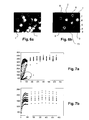
- the detection of a reaction of interest can be based on continuous readout of the fluorescence intensity of each functionalized encoded microparticle 1 present in a microfluidic channel, as depicted in figure 6a.
- Figure 6a clearly shows that it is difficult or even impossible to extract early quantitative information from the slopes at the origin when considering the intensity of each functionalized encoded microparticle 1 as a function of time. Therefore, the functionalized encoded microparticles 1 and the assay device described in WO 2010/072011 do not allow for a rapid quantification of reagent or ligand before an equilibrium states is reached, when the fluorescent signals saturate.
- the assay device of WO 2010/072011 decreases the time needed to reach equilibrium, in typical concentration values of analyte in the nano-molar range, ten to twenty minutes are still required, while lower concentration in the pico-molar range can take up to hours to be reached and serve for quantification. Moreover, the discrepancies in their fluorescent signals, in particular the diffusion pattern even after the equilibrium has been reached does not determine a quantitative information with a lower margin of error than about 15%.
- the present invention aims to remedy all or part of the disadvantages mentioned above.
- the present invention fulfills these objectives by providing an encoded microcarrier, comprising a readable code for identifying the microcarrier, said microcarrier comprising a body having at least a detection surface to detect a chemical and/or biological reaction, the microcarrier comprising at least a spacing element projecting from the body and shaped to ensure that, when the encoded microcarrier is laid on a flat plane with the detection surface facing said flat plane, a gap exists between said flat plane and this detection surface.
- the invention also relates to an assay system comprising a plurality of encoded microcarriers according to the invention and further comprising an assay device having at least a microfluidic channel shaped to accommodate a plurality of said encoded microcarriers, said microfluidic channel having at least an observation wall through which an assay is monitorable, wherein said microfluidic channel and spacing elements of each encoded microcarrier are shaped to ensure that, when said encoded microcarrier is introduced in said microfluidic channel with said detection surface facing said observation wall, a gap exists between said detection surface and said observation wall to allow a circulation of fluid in said gap.
- the invention concerns a method for performing a chemical and/or biological assay comprising a step of using at least an encoded microcarrier according to the invention, wherein a chemical and/or biological reaction is monitored on a detection surface of said encoded microcarrier.
- At least one encoded microcarrier according to the invention can be used in an assay device having a microfluidic channel to perform chemical and/or biological assays in a rapid, multiplex and quantitative manner.
- the encoded microcarrier according to the invention allows early quantitation in a multiplex quantitative analysis, typically in the first few seconds of the assay, therefore significantly decreasing the duration (typically dividing by at least ten the duration) of a quantitative analysis performed with the functionalized encoded microparticles described in WO 2010/072011 .
- an assay device also requires much less encoded microcarriers to obtain a reliable quantitative analysis, in comparison to the quantity of required functionalized encoded microparticles of the prior art, therefore increasing the level of multiplexing and reducing readout time.
- the encoded microcarrier is introduced in the microfluidic channel of the assay device with its detection surface facing the observation wall, a liquid solution containing the chemical and/or biological reagents used for the assays can flow in the gap between said detection surface and said observation wall generated by the spacing elements.
- the spacing elements permit to align the encoded microcarriers in the geometrical height of the microfluidic channel and therefore facilitate the flow of the liquid solution through the microfluidic channel.
- the exact positioning of the functionalized encoded microparticles 1 of the prior art is not controlled during their packing into the microfluidic channel and some of them are in contact with one of the surfaces of the microfluidic channel, notably the observation wall. Such contacts prevent a convective flow to occur between the touching surfaces (one of which can be the detection surface) and restrict the mass transfers of reagents to a diffusive flow for those detection surfaces of functionalized encoded microparticles in contact with a surface of the microfluidic channel.
- each spacing element prevents any contact between the detection surface and a wall of the microfluidic channel, forces a convective flow and avoids the reaction on the detection surface to be governed only by a diffusive flow.
- a particular wall of the microfluidic channel is for example an observation wall of an assay device.
- the contacting surface intended to be in contact with said flat plane represents less than 20% of the detection surface, preferably less than 15 %, more preferably less than 7%.
- a particular flat plane is for example an observation wall of an assay device.
- the detection surface has at least an area wherein, when said microcarrier is laid on a flat plane with the detection surface facing said flat plane, each point of said area belongs to two different cross-sections of said encoded microcarrier which are perpendicular to each other and to said plane, said cross-sections being free of spacing element.
- said contacting surface is only formed by all the spacing elements.
- the body has a cylindrical shape or a wafer shape.
- the detection surface is substantially flat.
- At least a spacing element is integral with said body. In another embodiment, at least a spacing element is a separated part which is bound to the body.
- the greatest distance between said detection surface and said flat plane is greater than 5 %, preferably greater than 10%, of the greatest height of the encoded microcarrier.
- this ratio reduces the fluidic resistance of a liquid flowing through when said encoded microcarriers are loaded in a microfluidic channel. Reducing the microfluidic resistance means that the number of encoded microcarriers loaded in a given microfluidic channel during an assay can be increased, increasing therefore the level of multiplexing. It has been found that the encoded microcarrier of the invention preserves the integrity of the assay device during an assay.
- each spacing element protrudes from at least a detection surface.
- each spacing element is shaped to ensure that, when the encoded microcarrier is laid on a flat plane with the detection surface facing said flat plane, said flat plane and said detection surface are substantially parallel to each other. Thereby the gap between the detection surface and said flat plane promote a laminar flow when the encoded microcarrier is loaded in a microfluidic channel.
- each spacing element is located at the periphery of the detection surface.
- the encoded microcarriers of the invention may be made from or comprise any material routinely used in high-throughput screening technology and diagnostics.
- Non-limiting examples of these materials include latex, polystyrene, cross-linked dextrans, polymethylstyrene, polycarbonate, polypropylene, cellulose, polyacrylamide, polydimethylacrylamide, fluorinated ethylene-propylene as well as materials commonly used in micro fabrication or micro milling such as glass, SiO2, silicon, PMMA (polymethylmethacrylate), polysilicon, molubden, polyimide, gold, silver, aluminum, steel or other metals or epoxy-based photosensitive materials such as SU-8.
- the encoded microcarrier may be of any shapes and sizes.
- the encoded microcarriers are made of silicon crystal.
- the encoded microcarrier of the invention is encoded in such a way that its function can be determined by reading the code.
- the body of the encoded microcarrier of the invention has a form of a wafer.
- wafer means that the body of the encoded microcarrier has two essentially parallel and essentially flat major surfaces, one of which at least serves as a detection surface, and that its height between the two major surfaces is notably smaller (e.g. by at least a factor of two) than both its width and its length.
- each major surface can have any shape; non limiting examples are a square, a rectangle, a circle, a triangle or a hexagon.
- encoded microcarriers with a body that has the form of a wafer are introduced in a microfluidic channel with a rectangular or close to rectangular section as described in patent application WO2010/072011 , they have their two major surfaces essentially facing two major surfaces of the microfluidic channel, one of which is the observation wall, and they can be easily detected by optical means through the observation wall.
- the encoded microcarriers have magnetic properties. Thereby they can be immobilized within the microfluidic channel.
- the method according to the invention further comprises a step of introducing one or more encoded microcarriers in a microfluidic channel of an assay device according to the invention.
- the method according to the invention further comprises a step of reading the attached code of said encoded microcarrier through said observation wall of the assay device.
- the method further comprising a step of reading the attached code of said encoded microcarrier through said observation wall of the assay device.
- An encoded microcarrier 2 of the invention shown in figures 2 , 4 , 5 and 6b , comprises a body 3 having a shape of a right circular cylinder delineated by a cylindrical surface 4 and two circular major surfaces 5, as shown in figures 2 , 4 , 5 and 6b ). At least one of these major surfaces 5 comprises a substantially flat detection surface 6, shown on pictures 2 and 5, to detect a chemical and/or biological reaction.
- a typical diameter of the encoded microcarrier 2 range from 1 to about 200 ⁇ m.
- the body 3 of said encoded microcarrier 2 has a form of a cylindrical wafer, meaning that the height of the right circular cylinder is notably smaller (by at least a factor two) than the radius of major surfaces 5.
- the detection surface 6 of the encoded microcarrier 2 is advantageously partially or totally functionalized.
- the encoded microcarrier 2 of the invention further comprises a readable code.
- the encoded microcarrier 2 is encoded and functionalized in such a way that its functionalization is determinable by reading its code.
- the code comprises a distinctive pattern of a plurality of traversing holes 7.
- the code also preferrably includes an asymetric orientation mark 8 such as a L-shaped sign ( figure 2 ) or a triange. This asymetric orientation mark 8 is meant to distinguish the major surfaces 5 from each other.
- An encoded microcarrier 2 according to the invention is made of silicon oxyde.
- An encoded microcarrier 2 of the invention can be shaped using dry and/or wet etching technology.
- an encoded microcarrier 2 comprises a plurality of spacing elements 9, shown in figures 2 and 5 , in particular twenty spacing elements 9, projecting from the body 3.
- the encoded microcarrier 2 with its spacing elements 9 is shaped to ensure that, when the encoded microcarrier 2 is laid on a flat plane 10 with the detection surface 6 facing said plane 10, a gap 11 exists between said flat plane 10 and the detection surface 6, as shown in figure 5 .
- Each spacing element 9 has a shape of a truncated right cylinder 12, is disposed on the periphery of the detection surface 6 and extends in the continuation of the cylindrical surface 4 to a distal end 13.
- Each circular right cylinder 12 is truncated along its height by the cylindrical surface 4 of the microcarrier 2.
- each spacing element 9 could have a shape of a truncated cone or of a spike.
- each spacing element 9 The heights of each spacing element 9 are equal to each other.
- the distal ends 13 of each spacing element 9 form together a contacting surface 14, illustrated in figure 2 , which is substantially parallel to the detection surface 6.
- this contacting surface 14 is intended to be in contact with said flat plane 10.
- the size of the contacting surface 14 represents less than 20% of the size of the detection surface 6, preferably less than 15%.
- each truncated right cylinder 12 allows defining the distance d, represented in figure 5 , between the detection surface 6 and said flat plane 10 on which the encoded microcarrier 2 is laid as described below ( figure 5 ).
- this distance d i.e. the height of the gap 11, is less than 30% of the greatest height H of the encoded microcarrier 2 ( figure 5 ).
- the distance d is greater than 5% of the height H, more preferably 10%.
- the Height H of the encoded microcarrier 2 is about 10 ⁇ m and the distance d is about 1 ⁇ m.
- the detection surface 6 further has an area 15 wherein, when the encoded microcarrier 2 is laid on the flat plane 10 with the detection surface 6 facing said flat plane 10, each point of said area 15 belongs to the two different cross-sections along the axis AA and BB, shown in figure 2 , which are perpendicular to each other and to said plane 10. Said cross-sections are free of spacing element 9. This ensures that, when the microcarrier 2 lays flat against said flat plane 10 and is in a laminar flow essentially parallel to that flat plane 10, the orientation of the microcarrier 2 around an axis normal to the flat plane 10 does not significantly affect the flow in the gap 11. In other words, there is no preferred rotational orientation of the microcarrier 2 with regard to the flow, which would change the efficacy of a reaction happening on the detection surface 6.
- Functionalized encoded microcarriers 2 are useful to perform chemical and/or biological assays in an assay system according to the invention. Indeed, the encoded microcarrier 2 serves as a support for chemical and/or biological assays. In this capacity, the encoded microcarrier 2 contains one or more ligands bound to its surface, in particular bound to the detection surface 6. When contacting the ligand-bound encoded microcarrier 2 with a solution that may contain one or more target analytes, a reaction of interest may occur on the detection surface 6, depending on the presence or absence of a proper analyte. As an example, a reaction of interest can emit or inhibit of fluorescent signal, which can be monitored. Detecting a reaction on the detection surface 6 can allow determining the presence or absence of particular analytes of interest.
- An assay system 100 comprises a plurality of encoded microcarriers 2 of the invention and further comprises an assay device 101, partially shown in figures 3 to 5 .
- the assay device 101 has at least a microfluidic channel 102 depicted in figures 3 to 5 .
- Such an assay device 101 is described for example in the patent application WO 2010/072011 , which is herein incorporated by reference in that respect.
- the microfluidic channel 102 comprises an inlet 103 and an outlet 104 and is shaped to accommodate a plurality of said encoded microcarriers 2.
- the microfluidic channel 102 is provided with stopping means 105 arranged in the vicinity of the outlet 104 of the microfluidic channel 102 and acting as filters that allow a liquid solution to flow through while blocking said encoded microcarriers 2 Inside.
- the microfluidic channel 102 has a cross-section that allows at least two encoded microcarriers 2 to be arranged side by side over the length of said microfluidic channel 102, in a monolayer arrangement as depicted in figure 4 .
- the size of the microfluidic channel 102 and of the encoded microcarrier 2 are chosen so that the height H of said encoded microcarrier 2 ranges from about 51% to about 95% of the smallest height D ( figure 5 ) of the microfluidic channel 102.
- the microfluidic channel 102 comprises at least a observation wall 106 through which an assay is monitorable. Typically, when the assay is monitored by fluorescent signal, the observation wall 106 is transparent.
- the spacing elements 9 when the encoded microcarriers 2 are loaded in the microfluidic channel 102 with said detection surface 6 facing said observation wall 106, the spacing elements 9 generate a gap 10 between said detection surface 6 and said observation wall 106 to allow a circulation of liquid in said gap 10.
- This liquid allowed to flow in the gap 10 contain chemical and/or biological reagent of interest for the assay.
- the set of encoded microparticles 1 and the set of encoded microcarriers 2 were then each loaded in two similar microfluidic channels 102 and both contacted with the same liquid containing a chemical reagent likely to react with said ligand and to produce a fluorescent signal, which was monitored.
- the liquid contained an anti-immunoglobulin G (anti-IgG).
- the figures 6a and 6b show the signal emitted respectively by the encoded microparticles 1 and the encoded microcarriers 2 within the first minute of the assays, at a concentration of about 100nM.
- the surface of a given encoded microparticle 1 of the prior art often shows diffusion pattern or line pattern, as illustrated in figure 6a .
- the encoded microcarriers 2 by the use of the spacing elements 9 exhibit a homogeneous signal on a given detection surface 6, as illustrated in figure 6b .
- the figures 7a and 7b show the quantitative measurements of fluorescent signals respectively for each encoded microparticle 1 or for each microcarrier 2 over the time.
- the encoded microparticles 1 exhibit significant discrepancies in their fluorescent signals from one microparticle to another, as shown in figure 7a , and eventually require a large statistical panel in order to extract significant information.
- spacing elements 9 permit a homogeneous convective flow all over the microfluidic channel 101 resulting in homogeneous fluorescent increase over time and across encoded microcarriers 2.
- the homogeneous signal increase allows for a rapid quantification of the analyte being flushed, from the first seconds, by looking at the fluorescence rate. This is not the case with encoded microparticles 1 of the prior art since the fluorescence signal increase is drown in artifacts from mass transfer defect as shown in area emphasized in figure 7a , without resorting to a large statistical panel of microparticles.
Abstract
The present invention relates to an encoded microcarrier (2) comprising a readable code attached to it for identification, said encoded microcarrier (2) comprising a body (3) having at least a detection surface (6) to detect a chemical and/or biological reaction, the microcarrier further comprising at least a spacing element (9) projecting from the body (3) and shaped to ensure that, when the encoded microcarrier (2) is laid on a flat plane with the detection surface (6) facing said flat plane, a gap exists between said flat plane and the detection surface (6). The invention also relates to an assay device designed to use a plurality of said encoded microcarriers (2) to perform assays. The invention relates finally to a method for monitoring a chemical or biological reaction.
Description
- The present invention relates to an encoded microcarrier, and more specifically to a microcarrier having spacing element, to an assay system, and to a method for performing a chemical and/or biological assay.
- Within the scope of the present invention, a microparticle or a microcarrier refer to any type of particles, respectively to any type of carriers, microscopic in size, typically with the largest dimension being from 100 nm to 300 micrometers, preferably from 1µm to 200 µm.
- According to the present invention, the term microcarrier refers to a microparticle functionalized, or designed to be functionalized, that is containing, or designed to contain, one or more ligands or functional units bound to the surface of the microcarriers or impregnated in its bulk. A large spectrum of chemical and biological molecules may be attached as ligands to a microcarrier. A microcarrier can have multiple functions and/or ligands. As used herein, the term functional unit is meant to define any species that modifies, attaches to, appends from, coats or is covalently or non-covalently bound to the surface of said microcarrier or impregnated in its bulk. These functions include all functions that are routinely used in high-throughput screening technology and diagnostics.
- Any reference in this disclosure to a code of a microcarrier or of a microparticle includes codes written on the surface of said microcarrier, or of said microparticle, as well as codes written at an internal depth of the microcarrier or microparticle. Such codes and methods for writing codes are disclosed, for example, in the
patent application WO 00/63695 patent application WO 00/63695 - Drug discovery or screening and DNA sequencing commonly involve performing assays on very large numbers of compounds or molecules. These assays typically include, for instance, screening chemical libraries for compounds of interest or particular target molecules, or testing for chemical and biological interactions of interest between molecules. Those assays often require carrying out thousands of individual chemical and/or biological reactions.
- A number of practical problems arise from the handling of such a large number of individual reactions. The most significant problem is probably the necessity to label and track each individual reaction.
- One conventional method of tracking the identity of the reactions is achieved by physically separating each reaction in a microtiter plate. The use of microtiter plate, however, carries several disadvantages like, in particular, a physical limitation to the size of microtiter plate used, and thus to the number of different reactions that may be carried out on the plate.
- In light of the limitations in the use of microarray, they are nowadays advantageously replaced by functionalized encoded microparticles to perform chemical and/or biological assays. Each functionalized encoded microparticle is provided with a code that uniquely identifies the particular ligand(s) bound to its surface. The use of such functionalized encoded microparticles allows for random processing, which means that thousands of uniquely functionalized encoded microparticles may all be mixed and subjected to an assay simultaneously. Examples of functionalized encoded microparticles are described in the international patent application
WO 00/63695 figure 1 . - The international patent application
WO 2010/072011 describes an assay device having at least a microfluidic channel which serves as a reaction chamber in which a plurality of functionalized encoded microparticles 1 (figure 1 ) can be packed. The microfluidic channel is provided with stopping means acting as filters that allow a liquid solution containing chemical and/or biological reagents to flow through while blocking the functionalized encodedmicroparticles 1 inside. The geometrical height of said microfluidic channels and the dimensions of said functionalized encodedmicroparticles 1 are chosen so that said microparticles are typically arranged in a monolayer arrangement inside each microfluidic channels preventing saidmicroparticles 1 to overlap each other. - Those functionalized encoded
microparticles 1 that show a favorable reaction of interest between their attached ligand(s) and the chemical and/or biological reagents flowing through may then have their code read, thereby leading to the identity of the ligand that produced the favorable reaction. - The term microfluidic channel refers to a closed channel, i.e. an elongated passage for fluids, with a cross-section microscopic in size, i.e. with the largest dimension of the cross-section being typically from about 1 to about 500 micrometers, preferably about 10 to about 300 micrometers. A microfluidic channel has a longitudinal direction, that is not necessarily a straight line, and that corresponds to the direction in which fluids are directed within the microfluidic channel, i.e preferably essentially to the direction corresponding to the average speed vector of the fluid, assuming a laminar flow regime.
- With the assay device described in
WO 2010/072011 , the detection of a reaction of interest can be based on continuous readout of the fluorescence intensity of each functionalized encodedmicroparticle 1 present in a microfluidic channel, as depicted infigure 6a. Figure 6a clearly shows that it is difficult or even impossible to extract early quantitative information from the slopes at the origin when considering the intensity of each functionalized encodedmicroparticle 1 as a function of time. Therefore, the functionalized encodedmicroparticles 1 and the assay device described inWO 2010/072011 do not allow for a rapid quantification of reagent or ligand before an equilibrium states is reached, when the fluorescent signals saturate. Although the assay device ofWO 2010/072011 decreases the time needed to reach equilibrium, in typical concentration values of analyte in the nano-molar range, ten to twenty minutes are still required, while lower concentration in the pico-molar range can take up to hours to be reached and serve for quantification. Moreover, the discrepancies in their fluorescent signals, in particular the diffusion pattern even after the equilibrium has been reached does not determine a quantitative information with a lower margin of error than about 15%. - The present invention aims to remedy all or part of the disadvantages mentioned above.
- The present invention fulfills these objectives by providing an encoded microcarrier, comprising a readable code for identifying the microcarrier, said microcarrier comprising a body having at least a detection surface to detect a chemical and/or biological reaction, the microcarrier comprising at least a spacing element projecting from the body and shaped to ensure that, when the encoded microcarrier is laid on a flat plane with the detection surface facing said flat plane, a gap exists between said flat plane and this detection surface.
- The invention also relates to an assay system comprising a plurality of encoded microcarriers according to the invention and further comprising an assay device having at least a microfluidic channel shaped to accommodate a plurality of said encoded microcarriers, said microfluidic channel having at least an observation wall through which an assay is monitorable, wherein said microfluidic channel and spacing elements of each encoded microcarrier are shaped to ensure that, when said encoded microcarrier is introduced in said microfluidic channel with said detection surface facing said observation wall, a gap exists between said detection surface and said observation wall to allow a circulation of fluid in said gap.
- Furthermore, the invention concerns a method for performing a chemical and/or biological assay comprising a step of using at least an encoded microcarrier according to the invention, wherein a chemical and/or biological reaction is monitored on a detection surface of said encoded microcarrier.
- Thus, at least one encoded microcarrier according to the invention can be used in an assay device having a microfluidic channel to perform chemical and/or biological assays in a rapid, multiplex and quantitative manner. The encoded microcarrier according to the invention allows early quantitation in a multiplex quantitative analysis, typically in the first few seconds of the assay, therefore significantly decreasing the duration (typically dividing by at least ten the duration) of a quantitative analysis performed with the functionalized encoded microparticles described in
WO 2010/072011 . It has also been discovered that an assay device according to the invention also requires much less encoded microcarriers to obtain a reliable quantitative analysis, in comparison to the quantity of required functionalized encoded microparticles of the prior art, therefore increasing the level of multiplexing and reducing readout time. When the encoded microcarrier is introduced in the microfluidic channel of the assay device with its detection surface facing the observation wall, a liquid solution containing the chemical and/or biological reagents used for the assays can flow in the gap between said detection surface and said observation wall generated by the spacing elements. The spacing elements permit to align the encoded microcarriers in the geometrical height of the microfluidic channel and therefore facilitate the flow of the liquid solution through the microfluidic channel. - The exact positioning of the functionalized encoded
microparticles 1 of the prior art is not controlled during their packing into the microfluidic channel and some of them are in contact with one of the surfaces of the microfluidic channel, notably the observation wall. Such contacts prevent a convective flow to occur between the touching surfaces (one of which can be the detection surface) and restrict the mass transfers of reagents to a diffusive flow for those detection surfaces of functionalized encoded microparticles in contact with a surface of the microfluidic channel. - To the opposite, with the encoded microcarrier of the present invention, each spacing element prevents any contact between the detection surface and a wall of the microfluidic channel, forces a convective flow and avoids the reaction on the detection surface to be governed only by a diffusive flow. A particular wall of the microfluidic channel is for example an observation wall of an assay device.
- According to an embodiment, when the encoded microcarrier is laid on a flat plane with the detection surface facing that flat plane, the contacting surface intended to be in contact with said flat plane represents less than 20% of the detection surface, preferably less than 15 %, more preferably less than 7%. Thereby it is possible to promote a mass transfer with respect to diffusive flow. A particular flat plane is for example an observation wall of an assay device.
- According to a technical feature, the detection surface has at least an area wherein, when said microcarrier is laid on a flat plane with the detection surface facing said flat plane, each point of said area belongs to two different cross-sections of said encoded microcarrier which are perpendicular to each other and to said plane, said cross-sections being free of spacing element. This technical feature ensures that, when the microcarrier lays flat against said flat plane and is in a laminar flow essentially parallel to that flat plane, the orientation of the microcarrier around an axis normal to the flat plane does not significantly affect the flow in the gap. In other words, there is no preferred rotational orientation of the microcarrier with regard to the flow, which would change the efficacy of a reaction happening on the detection surface.
- In an embodiment, said contacting surface is only formed by all the spacing elements.
- According to an embodiment of the invention, the body has a cylindrical shape or a wafer shape.
- In a preferred embodiment, the detection surface is substantially flat.
- In an embodiment, at least a spacing element is integral with said body. In another embodiment, at least a spacing element is a separated part which is bound to the body.
- According to an embodiment, when the encoded microcarrier is laid on a flat plane with a detection surface facing said flat plane, the greatest distance between said detection surface and said flat plane is greater than 5 %, preferably greater than 10%, of the greatest height of the encoded microcarrier. Thereby the size of the cross-section of the gap between the detection surface and the flat plane is increased while the congestion created by the encoded microcarrier in a microfluidic channel is reduced to allow a laminar flow in said microfluidic channel. Such an increased size of the cross-section of the gap will increase the speed of the flow relative to the detection surface and therefore increase the chances of contact between molecules of interest in the fluid solution and the ligand(s) attached to the encoded microcarrier. It increases the assay sensitivity. Moreover, this ratio reduces the fluidic resistance of a liquid flowing through when said encoded microcarriers are loaded in a microfluidic channel. Reducing the microfluidic resistance means that the number of encoded microcarriers loaded in a given microfluidic channel during an assay can be increased, increasing therefore the level of multiplexing. It has been found that the encoded microcarrier of the invention preserves the integrity of the assay device during an assay.
- In an embodiment, each spacing element protrudes from at least a detection surface.
- In a preferred embodiment, each spacing element is shaped to ensure that, when the encoded microcarrier is laid on a flat plane with the detection surface facing said flat plane, said flat plane and said detection surface are substantially parallel to each other. Thereby the gap between the detection surface and said flat plane promote a laminar flow when the encoded microcarrier is loaded in a microfluidic channel.
- According to one possibility, each spacing element is located at the periphery of the detection surface.
- The encoded microcarriers of the invention may be made from or comprise any material routinely used in high-throughput screening technology and diagnostics. Non-limiting examples of these materials include latex, polystyrene, cross-linked dextrans, polymethylstyrene, polycarbonate, polypropylene, cellulose, polyacrylamide, polydimethylacrylamide, fluorinated ethylene-propylene as well as materials commonly used in micro fabrication or micro milling such as glass, SiO2, silicon, PMMA (polymethylmethacrylate), polysilicon, molubden, polyimide, gold, silver, aluminum, steel or other metals or epoxy-based photosensitive materials such as SU-8. The encoded microcarrier may be of any shapes and sizes. Preferably, the encoded microcarriers are made of silicon crystal.
- In an embodiment, the encoded microcarrier of the invention is encoded in such a way that its function can be determined by reading the code.
- In a preferred embodiment, the body of the encoded microcarrier of the invention has a form of a wafer. The term wafer means that the body of the encoded microcarrier has two essentially parallel and essentially flat major surfaces, one of which at least serves as a detection surface, and that its height between the two major surfaces is notably smaller (e.g. by at least a factor of two) than both its width and its length.
- According to a technical feature, each major surface can have any shape; non limiting examples are a square, a rectangle, a circle, a triangle or a hexagon.
- Thus, when encoded microcarriers with a body that has the form of a wafer are introduced in a microfluidic channel with a rectangular or close to rectangular section as described in patent application
WO2010/072011 , they have their two major surfaces essentially facing two major surfaces of the microfluidic channel, one of which is the observation wall, and they can be easily detected by optical means through the observation wall. - In another embodiment, the encoded microcarriers have magnetic properties. Thereby they can be immobilized within the microfluidic channel.
- In an embodiment, the method according to the invention further comprises a step of introducing one or more encoded microcarriers in a microfluidic channel of an assay device according to the invention.
- In a preferred embodiment, the method according to the invention further comprises a step of reading the attached code of said encoded microcarrier through said observation wall of the assay device.
- In an embodiment, the method further comprising a step of reading the attached code of said encoded microcarrier through said observation wall of the assay device.
- The present invention is further illustrated by the following detailed description set forth in view of the appended drawings, which represent an exemplary and explanatory embodiment of an encoded microcarrier not restrictive of the invention, wherein:
-
figure 1 illustrates a top perspective view of encoded microparticles of the prior art; -
figure 2 illustrates a top perspective view of encoded microcarriers according to the invention; -
figure 3 illustrates a cross-section view of a microfluidic channel of an assay device according to the invention; -
figure 4 illustrates a top view of encoded microcarriers offigure 2 loaded in the microfluidic channel offigure 3 ; -
figure 5 illustrates a detailed cross-section view of encoded microcarriers offigure 2 loaded in the microfluidic channel offigures 3 and 4 . -
figure 6a illustrates fluorescent emissions on functionalized encoded microparticles offigure 1 observed within the first minute of an assay; -
figure 6b illustrates fluorescent emissions on encoded microcarriers offigure 2 observed within the first minute of an assay; -
figure 7a illustrates the kinetic curves of fluorescent signal occurring on functionalized encoded microparticles offigure 1 ; -
figure 7b illustrates a kinetic curves of fluorescent signal occurring on encoded microcarriers offigure 2 ; - An encoded
microcarrier 2 of the invention, shown infigures 2 ,4 ,5 and6b , comprises abody 3 having a shape of a right circular cylinder delineated by a cylindrical surface 4 and two circularmajor surfaces 5, as shown infigures 2 ,4 ,5 and6b ). At least one of thesemajor surfaces 5 comprises a substantiallyflat detection surface 6, shown onpictures microcarrier 2 range from 1 to about 200 µm. - The
body 3 of said encodedmicrocarrier 2 has a form of a cylindrical wafer, meaning that the height of the right circular cylinder is notably smaller (by at least a factor two) than the radius ofmajor surfaces 5. In order to be able to detect a chemical and/or biological reaction, thedetection surface 6 of the encodedmicrocarrier 2 is advantageously partially or totally functionalized. - The encoded
microcarrier 2 of the invention further comprises a readable code. Thereby, the encodedmicrocarrier 2 is encoded and functionalized in such a way that its functionalization is determinable by reading its code. As shown inFigures 2 and6b , the code comprises a distinctive pattern of a plurality of traversing holes 7. The code also preferrably includes anasymetric orientation mark 8 such as a L-shaped sign (figure 2 ) or a triange. Thisasymetric orientation mark 8 is meant to distinguish themajor surfaces 5 from each other. - An encoded
microcarrier 2 according to the invention is made of silicon oxyde. An encodedmicrocarrier 2 of the invention can be shaped using dry and/or wet etching technology. - Further, an encoded
microcarrier 2 according to the invention comprises a plurality ofspacing elements 9, shown infigures 2 and5 , in particular twentyspacing elements 9, projecting from thebody 3. The encodedmicrocarrier 2 with itsspacing elements 9 is shaped to ensure that, when the encodedmicrocarrier 2 is laid on aflat plane 10 with thedetection surface 6 facing saidplane 10, agap 11 exists between saidflat plane 10 and thedetection surface 6, as shown infigure 5 . - Each
spacing element 9 has a shape of a truncatedright cylinder 12, is disposed on the periphery of thedetection surface 6 and extends in the continuation of the cylindrical surface 4 to adistal end 13. Each circularright cylinder 12 is truncated along its height by the cylindrical surface 4 of themicrocarrier 2. - In an alternative, not shown in figures, each
spacing element 9 could have a shape of a truncated cone or of a spike. - The heights of each
spacing element 9 are equal to each other. The distal ends 13 of eachspacing element 9 form together a contactingsurface 14, illustrated infigure 2 , which is substantially parallel to thedetection surface 6. When said encodedmicrocarrier 2 is laid on theflat plane 10 with thedetection surface 6 facing such aflat plane 10, this contactingsurface 14 is intended to be in contact with saidflat plane 10. The size of the contactingsurface 14 represents less than 20% of the size of thedetection surface 6, preferably less than 15%. - Choosing the height of each truncated
right cylinder 12 allows defining the distance d, represented infigure 5 , between thedetection surface 6 and saidflat plane 10 on which the encodedmicrocarrier 2 is laid as described below (figure 5 ). Advantageously, this distance d, i.e. the height of thegap 11, is less than 30% of the greatest height H of the encoded microcarrier 2 (figure 5 ). Most preferably, the distance d is greater than 5% of the height H, more preferably 10%. In the example of the figures, The Height H of the encodedmicrocarrier 2 is about 10 µm and the distance d is about 1 µm. - The
detection surface 6 further has anarea 15 wherein, when the encodedmicrocarrier 2 is laid on theflat plane 10 with thedetection surface 6 facing saidflat plane 10, each point of saidarea 15 belongs to the two different cross-sections along the axis AA and BB, shown infigure 2 , which are perpendicular to each other and to saidplane 10. Said cross-sections are free ofspacing element 9. This ensures that, when themicrocarrier 2 lays flat against saidflat plane 10 and is in a laminar flow essentially parallel to thatflat plane 10, the orientation of themicrocarrier 2 around an axis normal to theflat plane 10 does not significantly affect the flow in thegap 11. In other words, there is no preferred rotational orientation of themicrocarrier 2 with regard to the flow, which would change the efficacy of a reaction happening on thedetection surface 6. - Functionalized encoded
microcarriers 2 are useful to perform chemical and/or biological assays in an assay system according to the invention. Indeed, the encodedmicrocarrier 2 serves as a support for chemical and/or biological assays. In this capacity, the encodedmicrocarrier 2 contains one or more ligands bound to its surface, in particular bound to thedetection surface 6. When contacting the ligand-bound encodedmicrocarrier 2 with a solution that may contain one or more target analytes, a reaction of interest may occur on thedetection surface 6, depending on the presence or absence of a proper analyte. As an example, a reaction of interest can emit or inhibit of fluorescent signal, which can be monitored. Detecting a reaction on thedetection surface 6 can allow determining the presence or absence of particular analytes of interest. - An
assay system 100 according to the invention comprises a plurality of encodedmicrocarriers 2 of the invention and further comprises anassay device 101, partially shown infigures 3 to 5 . Theassay device 101 has at least amicrofluidic channel 102 depicted infigures 3 to 5 . Such anassay device 101 is described for example in the patent applicationWO 2010/072011 , which is herein incorporated by reference in that respect. Themicrofluidic channel 102 comprises aninlet 103 and anoutlet 104 and is shaped to accommodate a plurality of said encodedmicrocarriers 2. Themicrofluidic channel 102 is provided with stoppingmeans 105 arranged in the vicinity of theoutlet 104 of themicrofluidic channel 102 and acting as filters that allow a liquid solution to flow through while blocking said encodedmicrocarriers 2 Inside. Themicrofluidic channel 102 has a cross-section that allows at least two encodedmicrocarriers 2 to be arranged side by side over the length of saidmicrofluidic channel 102, in a monolayer arrangement as depicted infigure 4 . The size of themicrofluidic channel 102 and of the encodedmicrocarrier 2 are chosen so that the height H of said encodedmicrocarrier 2 ranges from about 51% to about 95% of the smallest height D (figure 5 ) of themicrofluidic channel 102. - The
microfluidic channel 102 comprises at least aobservation wall 106 through which an assay is monitorable. Typically, when the assay is monitored by fluorescent signal, theobservation wall 106 is transparent. - In a system according to the present invention, when the encoded
microcarriers 2 are loaded in themicrofluidic channel 102 with saiddetection surface 6 facing saidobservation wall 106, thespacing elements 9 generate agap 10 between saiddetection surface 6 and saidobservation wall 106 to allow a circulation of liquid in saidgap 10. This liquid allowed to flow in thegap 10 contain chemical and/or biological reagent of interest for the assay. - In order to demonstrate the advantage of using encoded
microcarriers 2 in theassay system 100 according to the invention instead of using an existing assay system, a set of encodedmicroparticles 1 of the prior art and a set of encodedmicrocarriers 2 have been both functionalized with the same ligand, in the same conditions. The chemistry involved in order to functionalize said encodedmicrocarrier 2 or said encoded microparticle is well known and implies first a silanization of the surface silanol groups followed by an oxidation into carboxyl groups prior to binding a ligand. In the assay described here, the ligand bound on the surfaces was the protein Immunoglobulin G antibody (IgG). The set of encodedmicroparticles 1 and the set of encodedmicrocarriers 2 were then each loaded in two similarmicrofluidic channels 102 and both contacted with the same liquid containing a chemical reagent likely to react with said ligand and to produce a fluorescent signal, which was monitored. For the current assay, the liquid contained an anti-immunoglobulin G (anti-IgG). - The
figures 6a and 6b show the signal emitted respectively by the encodedmicroparticles 1 and the encodedmicrocarriers 2 within the first minute of the assays, at a concentration of about 100nM. - The surface of a given encoded
microparticle 1 of the prior art often shows diffusion pattern or line pattern, as illustrated infigure 6a . To the opposite, the encodedmicrocarriers 2 by the use of thespacing elements 9 exhibit a homogeneous signal on a givendetection surface 6, as illustrated infigure 6b . - The
figures 7a and 7b show the quantitative measurements of fluorescent signals respectively for each encodedmicroparticle 1 or for eachmicrocarrier 2 over the time. The encodedmicroparticles 1 exhibit significant discrepancies in their fluorescent signals from one microparticle to another, as shown infigure 7a , and eventually require a large statistical panel in order to extract significant information. - To the opposite, during the first minutes of an assay, the signals recorded on each detection surfaces 6 of each encoded
microcarrier 2 do not exhibit discrepancies with each other, as shown infigure 7b . - Thus the
spacing elements 9 permit a homogeneous convective flow all over themicrofluidic channel 101 resulting in homogeneous fluorescent increase over time and across encodedmicrocarriers 2. - The homogeneous signal increase allows for a rapid quantification of the analyte being flushed, from the first seconds, by looking at the fluorescence rate. This is not the case with encoded
microparticles 1 of the prior art since the fluorescence signal increase is drown in artifacts from mass transfer defect as shown in area emphasized infigure 7a , without resorting to a large statistical panel of microparticles. - Other embodiments of the invention will be apparent to those skilled in the art from consideration of the specification and practice of the invention disclosed herein. It is intended that the specification and examples be considered as exemplary only, with the true scope and spirit of the invention being indicated by the following claims.
Claims (15)
- An encoded microcarrier (2), comprising a readable code for identifying the microcarrier, said microcarrier comprising a body (3) having at least a detection surface (6) to detect a chemical and/or biological reaction, characterized in that the microcarrier comprises at least a spacing element (9) projecting from the body (3) and shaped to ensure that, when the encoded microcarrier (2) is laid on a flat plane (10) with the detection surface (6) facing said flat plane (10), a gap (11) exists between said flat plane (10) and this detection surface (6).
- An encoded microcarrier (2) according to claim 1, wherein, when the encoded microcarrier (2) is laid on a flat plane (10) with the detection surface (6) facing that flat plane (10), the size of the contacting surface (14) intended to be in contact with said flat plane (10) represents less than 30% of the size of the detection surface (6), preferably less than 10 %, more preferably less than 5 %.
- An encoded microcarrier (2) according to claim 1 or 2, wherein the detection surface (6) has at least an area wherein, when said microcarrier is laid on a flat plane (10) with the detection surface (6) facing said flat plane (10), each point of said area belongs to two different cross-sections of said encoded microcarrier (2) which are perpendicular to each other and to said plane (10), said cross-sections being free of spacing element (9).
- An encoded microcarrier (2) according to any one of claims 1 to 3, wherein, when the encoded microcarrier (2) is laid on a flat plane (10) with a detection surface (6) facing said flat plane (10), the greatest distance (d) between said detection surface (6) and said flat plane (10) is greater than 5% of the greatest height (H) of the encoded microcarrier (2), preferably greater than 10%.
- An encoded microcarrier (2) according to any one of claims 1 to 4, wherein said contacting surface (14) is only formed by all the spacing elements (9).
- An encoded microcarrier (2) according to any one of claims 1 to 5, wherein said body (3) has a cylindrical shape or a wafer shape.
- An encoded microcarrier (2) according to any one of claims 1 to 6, wherein the detection surface (6) is substantially flat.
- An encoded microcarrier (2) according to claim 7, wherein each spacing element (9) is shaped to ensure that, when the encoded microcarrier (2) is laid on a flat plane (10) with the detection surface (6) facing said flat plane (10), said flat plane (10) and said detection surface (6) are substantially parallel to each other.
- An encoded microcarrier (2) according to any one of claims 1 to 8, wherein each spacing element (9) protrudes from at least a detection surface (6).
- An encoded microcarrier (2) according to any one of claims 1 to 9, wherein each spacing element (9) is located at the periphery of the detection surface (6).
- An assay system (100) comprising a plurality of encoded microcarriers (2) according to any one of claims 1 to 10 and further comprising an assay device (101) having at least a microfluidic channel (102) shaped to accommodate a plurality of said encoded microcarriers (2), said microfluidic channel (102) having at least a observation wall (106) through which an assay is monitorable, wherein said microfluidic channel (102) and spacing elements (9) of each encoded microcarrier (2) are shaped to ensure that, when said encoded microcarrier (2) is introduced in said microfluidic channel (102) with said detection surface (6) facing said observation wall (106), a gap (10) exists between said detection surface (6) and said observation wall (106) to allow a circulation of fluid in said gap (10).
- A method for performing a chemical and/or biological assay comprising a step of using at least an encoded microcarrier (2) according to claim 1 to 11, wherein a chemical and/or biological reaction is monitored on a detection surface (6) of said encoded microcarrier (2).
- A method according to claim 12, further comprising a step of introducing one or more encoded microcarriers (2) in a microfluidic channel (102) of an assay device (101) according to claim 11.
- A method according to claim 13, further comprising a step of monitoring the at least one chemical and/or biological reaction through said observation wall (106) of the assay device (101).
- A method according to claim 13 or 14, further comprising a step of reading the attached code of said encoded microcarrier (2) through said observation wall (106) of the assay device (101).
Priority Applications (12)
| Application Number | Priority Date | Filing Date | Title |
|---|---|---|---|
| EP11000970A EP2484447A1 (en) | 2011-02-07 | 2011-02-07 | Improved encoded microcarriers, assay system using them and method for performing an assay |
| JP2013552083A JP6042348B2 (en) | 2011-02-07 | 2012-02-06 | Improved coded microcarriers, assay systems using them, and methods for performing assays |
| EP12703428.8A EP2673086B1 (en) | 2011-02-07 | 2012-02-06 | Improved encoded microcarriers, assay system comprising them and method for performing an assay |
| CA2819099A CA2819099A1 (en) | 2011-02-07 | 2012-02-06 | Encoded macrocarriers, assay system for use thereof and method for performing an assay |
| KR1020137017935A KR101948162B1 (en) | 2011-02-07 | 2012-02-06 | Improved encoded macrocarriers, assay system using them and method for performing an assay |
| RU2013140344/05A RU2599304C2 (en) | 2011-02-07 | 2012-02-06 | Improved coded microcarriers, test systems and analysis methods using them |
| US13/980,721 US9310305B2 (en) | 2011-02-07 | 2012-02-06 | Encoded microcarriers, assay system using them and method for performing an assay |
| BR112013018236A BR112013018236A2 (en) | 2011-02-07 | 2012-02-06 | enhanced coded microcarriers, assay system using them and method for performing an assay |
| CN201280004353.8A CN103282126B (en) | 2011-02-07 | 2012-02-06 | Improve coding microcarrier, use they Analytical system and for carrying out method for measuring |
| ES12703428T ES2776523T3 (en) | 2011-02-07 | 2012-02-06 | Enhanced Coded Microcarriers, Assay System Comprising Them, and Method of Performing an Assay |
| AU2012214080A AU2012214080B8 (en) | 2011-02-07 | 2012-02-06 | Improved encoded microcarriers, assay system using them and method for performing an assay |
| PCT/CH2012/000032 WO2012106827A1 (en) | 2011-02-07 | 2012-02-06 | Improved encoded macrocarriers, assay system using them and method for performing an assay |
Applications Claiming Priority (1)
| Application Number | Priority Date | Filing Date | Title |
|---|---|---|---|
| EP11000970A EP2484447A1 (en) | 2011-02-07 | 2011-02-07 | Improved encoded microcarriers, assay system using them and method for performing an assay |
Publications (1)
| Publication Number | Publication Date |
|---|---|
| EP2484447A1 true EP2484447A1 (en) | 2012-08-08 |
Family
ID=44247800
Family Applications (2)
| Application Number | Title | Priority Date | Filing Date |
|---|---|---|---|
| EP11000970A Withdrawn EP2484447A1 (en) | 2011-02-07 | 2011-02-07 | Improved encoded microcarriers, assay system using them and method for performing an assay |
| EP12703428.8A Active EP2673086B1 (en) | 2011-02-07 | 2012-02-06 | Improved encoded microcarriers, assay system comprising them and method for performing an assay |
Family Applications After (1)
| Application Number | Title | Priority Date | Filing Date |
|---|---|---|---|
| EP12703428.8A Active EP2673086B1 (en) | 2011-02-07 | 2012-02-06 | Improved encoded microcarriers, assay system comprising them and method for performing an assay |
Country Status (11)
| Country | Link |
|---|---|
| US (1) | US9310305B2 (en) |
| EP (2) | EP2484447A1 (en) |
| JP (1) | JP6042348B2 (en) |
| KR (1) | KR101948162B1 (en) |
| CN (1) | CN103282126B (en) |
| AU (1) | AU2012214080B8 (en) |
| BR (1) | BR112013018236A2 (en) |
| CA (1) | CA2819099A1 (en) |
| ES (1) | ES2776523T3 (en) |
| RU (1) | RU2599304C2 (en) |
| WO (1) | WO2012106827A1 (en) |
Cited By (8)
| Publication number | Priority date | Publication date | Assignee | Title |
|---|---|---|---|---|
| WO2015024863A1 (en) * | 2013-08-21 | 2015-02-26 | Mycartis Nv | Heterogenous surface functionalization |
| US9682377B2 (en) | 2012-07-11 | 2017-06-20 | Mycartis Nv | Method for injecting microparticles into a microfluidic channel |
| US10019815B2 (en) | 2016-03-17 | 2018-07-10 | Plexbio Co., Ltd. | Methods and systems for image differentiated multiplex assays |
| US10302640B2 (en) | 2015-06-11 | 2019-05-28 | Plexbio Co., Ltd. | Image differentiated multiplex assays |
| US10436776B2 (en) | 2015-11-20 | 2019-10-08 | Plexbio Co., Ltd. | Methods and systems for selection of detection area |
| US10894975B2 (en) | 2016-12-09 | 2021-01-19 | Plexbio Co., Ltd. | Image differentiated multiplex assays for multiplex detection of DNA mutations |
| CN113607682A (en) * | 2021-07-30 | 2021-11-05 | 复旦大学 | Coding microcarrier material and application thereof |
| US11796535B2 (en) | 2016-09-16 | 2023-10-24 | Plexbio Co., Ltd. | Methods and systems for multiplex assays |
Families Citing this family (9)
| Publication number | Priority date | Publication date | Assignee | Title |
|---|---|---|---|---|
| EP2690058A1 (en) * | 2012-07-24 | 2014-01-29 | Biocartis SA | Method for producing microcarriers and for performing biological assays |
| EP2690057A1 (en) * | 2012-07-24 | 2014-01-29 | Biocartis SA | Method for producing structured microcarriers |
| AU2014289499A1 (en) | 2013-07-09 | 2015-11-19 | Nestec S.A. | Microfluidic collaborative enzyme enhanced reactive CEER immunoassay |
| CN103645308B (en) * | 2013-12-09 | 2015-06-03 | 东南大学 | Two-dimensional coding method of micro-carrier |
| CN105772117A (en) * | 2014-12-22 | 2016-07-20 | 卡梅德生物科技(天津)有限公司 | Experimental chip used for detection of chemical components in biological laboratory |
| EP3314269A4 (en) | 2015-06-26 | 2019-01-23 | Abbott Laboratories | Reaction vessel exchanger device for a diagnostic analyzer |
| EP3147650A1 (en) * | 2015-09-22 | 2017-03-29 | MyCartis N.V. | Cross-talk correction in multiplexing analysis of biological sample |
| US11366109B2 (en) * | 2018-12-06 | 2022-06-21 | Winmems Technologies Co., Ltd. | Encoded microflakes |
| JP7160005B2 (en) | 2019-09-10 | 2022-10-25 | 日立金属株式会社 | Temperature detection circuit for magnetostrictive sensor, magnetostrictive sensor, and temperature detection method for magnetostrictive sensor |
Citations (4)
| Publication number | Priority date | Publication date | Assignee | Title |
|---|---|---|---|---|
| WO2000063695A1 (en) | 1999-04-16 | 2000-10-26 | Tibotec N.V. | Encoding of microcarriers |
| EP1464700A1 (en) * | 2002-01-17 | 2004-10-06 | Precision System Science Co., Ltd. | SYSTEM FOR HOUSING/PROCESSING CARRIER AND METHOD FOR HOUSING/PROCESSING CARRIER |
| GB2404918A (en) * | 2003-08-11 | 2005-02-16 | Toshiba Res Europ Ltd | An encoded carrier |
| WO2010072011A1 (en) | 2008-12-23 | 2010-07-01 | Biocartis Sa | Assay device and method for performing biological assays |
Family Cites Families (13)
| Publication number | Priority date | Publication date | Assignee | Title |
|---|---|---|---|---|
| WO2000061198A1 (en) * | 1999-04-12 | 2000-10-19 | Hitachi Chemical Co., Ltd. | Method of producing probe arrays for biological materials using fine particles |
| US20030129654A1 (en) * | 1999-04-15 | 2003-07-10 | Ilya Ravkin | Coded particles for multiplexed analysis of biological samples |
| BR0114757A (en) * | 2000-10-19 | 2003-10-07 | Tibotec Bvba | Method and device for handling micro-vehicles for identification purposes |
| US20030087425A1 (en) * | 2001-11-07 | 2003-05-08 | Eggers Mitchell D | Sample carrier |
| CA2498913A1 (en) * | 2002-09-12 | 2004-03-25 | Cyvera Corporation | Assay stick comprising coded microbeads |
| US20050079506A1 (en) * | 2003-10-09 | 2005-04-14 | Eastman Kodak Company | Filled, biological microarray and method for use |
| WO2005079544A2 (en) * | 2004-02-19 | 2005-09-01 | Cyvera Corporation | Multi-well plate with alignment grooves for encoded microparticles |
| PT1773978E (en) * | 2004-05-19 | 2014-05-29 | Massachusetts Inst Technology | Perfused three-dimensional cell/tissue disease models |
| JP2006300548A (en) * | 2005-04-15 | 2006-11-02 | Hitachi Software Eng Co Ltd | Inspection chip and inspection chip system |
| EP1903337B1 (en) * | 2006-09-20 | 2015-07-22 | Mycartis N.V. | Coating for microcarriers |
| US7947487B2 (en) * | 2006-10-05 | 2011-05-24 | Massachusetts Institute Of Technology | Multifunctional encoded particles for high-throughput analysis |
| US9631169B2 (en) * | 2008-06-05 | 2017-04-25 | Invivo Sciences Inc. | Three dimensional tissues for high-throughput assays |
| JP2011000040A (en) * | 2009-06-18 | 2011-01-06 | Ihi Corp | Method for evaluating shear force influence |
-
2011
- 2011-02-07 EP EP11000970A patent/EP2484447A1/en not_active Withdrawn
-
2012
- 2012-02-06 CA CA2819099A patent/CA2819099A1/en not_active Abandoned
- 2012-02-06 KR KR1020137017935A patent/KR101948162B1/en active IP Right Grant
- 2012-02-06 AU AU2012214080A patent/AU2012214080B8/en not_active Ceased
- 2012-02-06 RU RU2013140344/05A patent/RU2599304C2/en not_active IP Right Cessation
- 2012-02-06 BR BR112013018236A patent/BR112013018236A2/en not_active Application Discontinuation
- 2012-02-06 ES ES12703428T patent/ES2776523T3/en active Active
- 2012-02-06 CN CN201280004353.8A patent/CN103282126B/en not_active Expired - Fee Related
- 2012-02-06 US US13/980,721 patent/US9310305B2/en active Active
- 2012-02-06 JP JP2013552083A patent/JP6042348B2/en not_active Expired - Fee Related
- 2012-02-06 WO PCT/CH2012/000032 patent/WO2012106827A1/en active Application Filing
- 2012-02-06 EP EP12703428.8A patent/EP2673086B1/en active Active
Patent Citations (4)
| Publication number | Priority date | Publication date | Assignee | Title |
|---|---|---|---|---|
| WO2000063695A1 (en) | 1999-04-16 | 2000-10-26 | Tibotec N.V. | Encoding of microcarriers |
| EP1464700A1 (en) * | 2002-01-17 | 2004-10-06 | Precision System Science Co., Ltd. | SYSTEM FOR HOUSING/PROCESSING CARRIER AND METHOD FOR HOUSING/PROCESSING CARRIER |
| GB2404918A (en) * | 2003-08-11 | 2005-02-16 | Toshiba Res Europ Ltd | An encoded carrier |
| WO2010072011A1 (en) | 2008-12-23 | 2010-07-01 | Biocartis Sa | Assay device and method for performing biological assays |
Cited By (11)
| Publication number | Priority date | Publication date | Assignee | Title |
|---|---|---|---|---|
| US9682377B2 (en) | 2012-07-11 | 2017-06-20 | Mycartis Nv | Method for injecting microparticles into a microfluidic channel |
| WO2015024863A1 (en) * | 2013-08-21 | 2015-02-26 | Mycartis Nv | Heterogenous surface functionalization |
| US10001478B2 (en) | 2013-08-21 | 2018-06-19 | Mycartis Nv | Heterogenous surface functionalization |
| US10302640B2 (en) | 2015-06-11 | 2019-05-28 | Plexbio Co., Ltd. | Image differentiated multiplex assays |
| US10859910B2 (en) | 2015-06-11 | 2020-12-08 | Plexbio Co., Ltd. | Image differentiated multiplex assays |
| US11579522B2 (en) | 2015-06-11 | 2023-02-14 | Plexbio Co., Ltd. | Image differentiated multiplex assays |
| US10436776B2 (en) | 2015-11-20 | 2019-10-08 | Plexbio Co., Ltd. | Methods and systems for selection of detection area |
| US10019815B2 (en) | 2016-03-17 | 2018-07-10 | Plexbio Co., Ltd. | Methods and systems for image differentiated multiplex assays |
| US11796535B2 (en) | 2016-09-16 | 2023-10-24 | Plexbio Co., Ltd. | Methods and systems for multiplex assays |
| US10894975B2 (en) | 2016-12-09 | 2021-01-19 | Plexbio Co., Ltd. | Image differentiated multiplex assays for multiplex detection of DNA mutations |
| CN113607682A (en) * | 2021-07-30 | 2021-11-05 | 复旦大学 | Coding microcarrier material and application thereof |
Also Published As
| Publication number | Publication date |
|---|---|
| JP2014504733A (en) | 2014-02-24 |
| CA2819099A1 (en) | 2012-08-16 |
| KR101948162B1 (en) | 2019-02-14 |
| CN103282126B (en) | 2015-12-23 |
| BR112013018236A2 (en) | 2016-11-08 |
| US9310305B2 (en) | 2016-04-12 |
| EP2673086B1 (en) | 2020-01-15 |
| KR20140035875A (en) | 2014-03-24 |
| WO2012106827A1 (en) | 2012-08-16 |
| RU2013140344A (en) | 2015-03-20 |
| AU2012214080A1 (en) | 2013-07-04 |
| AU2012214080B8 (en) | 2015-05-14 |
| US20130302910A1 (en) | 2013-11-14 |
| RU2599304C2 (en) | 2016-10-10 |
| CN103282126A (en) | 2013-09-04 |
| ES2776523T3 (en) | 2020-07-30 |
| EP2673086A1 (en) | 2013-12-18 |
| JP6042348B2 (en) | 2016-12-14 |
| AU2012214080B2 (en) | 2015-05-07 |
Similar Documents
| Publication | Publication Date | Title |
|---|---|---|
| EP2673086B1 (en) | Improved encoded microcarriers, assay system comprising them and method for performing an assay | |
| RU2527686C2 (en) | Analysis device and method for performing biological analyses | |
| KR20040076226A (en) | Detection of agglutination of assays | |
| EP2877424B1 (en) | Method for producing structured microcarriers and corresponding microcarrier | |
| US9625455B2 (en) | Method and device for performing biological and/or chemical assays | |
| JP4536536B2 (en) | Fluid handling equipment | |
| EP2690058A1 (en) | Method for producing microcarriers and for performing biological assays | |
| WO2014009210A1 (en) | Method for injecting microparticles into a microfluidic channel |
Legal Events
| Date | Code | Title | Description |
|---|---|---|---|
| PUAI | Public reference made under article 153(3) epc to a published international application that has entered the european phase |
Free format text: ORIGINAL CODE: 0009012 |
|
| AK | Designated contracting states |
Kind code of ref document: A1 Designated state(s): AL AT BE BG CH CY CZ DE DK EE ES FI FR GB GR HR HU IE IS IT LI LT LU LV MC MK MT NL NO PL PT RO RS SE SI SK SM TR |
|
| AX | Request for extension of the european patent |
Extension state: BA ME |
|
| 17P | Request for examination filed |
Effective date: 20130125 |
|
| RAP1 | Party data changed (applicant data changed or rights of an application transferred) |
Owner name: BIOCARTIS SA |
|
| STAA | Information on the status of an ep patent application or granted ep patent |
Free format text: STATUS: THE APPLICATION IS DEEMED TO BE WITHDRAWN |
|
| 18D | Application deemed to be withdrawn |
Effective date: 20140902 |