EP2484317B1 - Lumbar support device - Google Patents
Lumbar support device Download PDFInfo
- Publication number
- EP2484317B1 EP2484317B1 EP10818583.6A EP10818583A EP2484317B1 EP 2484317 B1 EP2484317 B1 EP 2484317B1 EP 10818583 A EP10818583 A EP 10818583A EP 2484317 B1 EP2484317 B1 EP 2484317B1
- Authority
- EP
- European Patent Office
- Prior art keywords
- section
- user
- upper body
- assistance apparatus
- rotation
- Prior art date
- Legal status (The legal status is an assumption and is not a legal conclusion. Google has not performed a legal analysis and makes no representation as to the accuracy of the status listed.)
- Active
Links
Images












Classifications
-
- A—HUMAN NECESSITIES
- A61—MEDICAL OR VETERINARY SCIENCE; HYGIENE
- A61F—FILTERS IMPLANTABLE INTO BLOOD VESSELS; PROSTHESES; DEVICES PROVIDING PATENCY TO, OR PREVENTING COLLAPSING OF, TUBULAR STRUCTURES OF THE BODY, e.g. STENTS; ORTHOPAEDIC, NURSING OR CONTRACEPTIVE DEVICES; FOMENTATION; TREATMENT OR PROTECTION OF EYES OR EARS; BANDAGES, DRESSINGS OR ABSORBENT PADS; FIRST-AID KITS
- A61F5/00—Orthopaedic methods or devices for non-surgical treatment of bones or joints; Nursing devices ; Anti-rape devices
- A61F5/01—Orthopaedic devices, e.g. long-term immobilising or pressure directing devices for treating broken or deformed bones such as splints, casts or braces
-
- A—HUMAN NECESSITIES
- A61—MEDICAL OR VETERINARY SCIENCE; HYGIENE
- A61F—FILTERS IMPLANTABLE INTO BLOOD VESSELS; PROSTHESES; DEVICES PROVIDING PATENCY TO, OR PREVENTING COLLAPSING OF, TUBULAR STRUCTURES OF THE BODY, e.g. STENTS; ORTHOPAEDIC, NURSING OR CONTRACEPTIVE DEVICES; FOMENTATION; TREATMENT OR PROTECTION OF EYES OR EARS; BANDAGES, DRESSINGS OR ABSORBENT PADS; FIRST-AID KITS
- A61F5/00—Orthopaedic methods or devices for non-surgical treatment of bones or joints; Nursing devices ; Anti-rape devices
- A61F5/01—Orthopaedic devices, e.g. long-term immobilising or pressure directing devices for treating broken or deformed bones such as splints, casts or braces
- A61F5/02—Orthopaedic corsets
-
- A—HUMAN NECESSITIES
- A61—MEDICAL OR VETERINARY SCIENCE; HYGIENE
- A61F—FILTERS IMPLANTABLE INTO BLOOD VESSELS; PROSTHESES; DEVICES PROVIDING PATENCY TO, OR PREVENTING COLLAPSING OF, TUBULAR STRUCTURES OF THE BODY, e.g. STENTS; ORTHOPAEDIC, NURSING OR CONTRACEPTIVE DEVICES; FOMENTATION; TREATMENT OR PROTECTION OF EYES OR EARS; BANDAGES, DRESSINGS OR ABSORBENT PADS; FIRST-AID KITS
- A61F5/00—Orthopaedic methods or devices for non-surgical treatment of bones or joints; Nursing devices ; Anti-rape devices
- A61F5/01—Orthopaedic devices, e.g. long-term immobilising or pressure directing devices for treating broken or deformed bones such as splints, casts or braces
- A61F5/02—Orthopaedic corsets
- A61F5/026—Back straightening devices with shoulder braces to force back the shoulder to obtain a correct curvature of the spine
-
- A—HUMAN NECESSITIES
- A61—MEDICAL OR VETERINARY SCIENCE; HYGIENE
- A61F—FILTERS IMPLANTABLE INTO BLOOD VESSELS; PROSTHESES; DEVICES PROVIDING PATENCY TO, OR PREVENTING COLLAPSING OF, TUBULAR STRUCTURES OF THE BODY, e.g. STENTS; ORTHOPAEDIC, NURSING OR CONTRACEPTIVE DEVICES; FOMENTATION; TREATMENT OR PROTECTION OF EYES OR EARS; BANDAGES, DRESSINGS OR ABSORBENT PADS; FIRST-AID KITS
- A61F5/00—Orthopaedic methods or devices for non-surgical treatment of bones or joints; Nursing devices ; Anti-rape devices
- A61F5/01—Orthopaedic devices, e.g. long-term immobilising or pressure directing devices for treating broken or deformed bones such as splints, casts or braces
- A61F5/0102—Orthopaedic devices, e.g. long-term immobilising or pressure directing devices for treating broken or deformed bones such as splints, casts or braces specially adapted for correcting deformities of the limbs or for supporting them; Ortheses, e.g. with articulations
- A61F2005/0132—Additional features of the articulation
- A61F2005/0158—Additional features of the articulation with locking means
- A61F2005/016—Additional features of the articulation with locking means in standing position
-
- A—HUMAN NECESSITIES
- A61—MEDICAL OR VETERINARY SCIENCE; HYGIENE
- A61F—FILTERS IMPLANTABLE INTO BLOOD VESSELS; PROSTHESES; DEVICES PROVIDING PATENCY TO, OR PREVENTING COLLAPSING OF, TUBULAR STRUCTURES OF THE BODY, e.g. STENTS; ORTHOPAEDIC, NURSING OR CONTRACEPTIVE DEVICES; FOMENTATION; TREATMENT OR PROTECTION OF EYES OR EARS; BANDAGES, DRESSINGS OR ABSORBENT PADS; FIRST-AID KITS
- A61F5/00—Orthopaedic methods or devices for non-surgical treatment of bones or joints; Nursing devices ; Anti-rape devices
- A61F5/01—Orthopaedic devices, e.g. long-term immobilising or pressure directing devices for treating broken or deformed bones such as splints, casts or braces
- A61F5/0102—Orthopaedic devices, e.g. long-term immobilising or pressure directing devices for treating broken or deformed bones such as splints, casts or braces specially adapted for correcting deformities of the limbs or for supporting them; Ortheses, e.g. with articulations
- A61F2005/0132—Additional features of the articulation
- A61F2005/0169—Additional features of the articulation with damping means
-
- A—HUMAN NECESSITIES
- A61—MEDICAL OR VETERINARY SCIENCE; HYGIENE
- A61F—FILTERS IMPLANTABLE INTO BLOOD VESSELS; PROSTHESES; DEVICES PROVIDING PATENCY TO, OR PREVENTING COLLAPSING OF, TUBULAR STRUCTURES OF THE BODY, e.g. STENTS; ORTHOPAEDIC, NURSING OR CONTRACEPTIVE DEVICES; FOMENTATION; TREATMENT OR PROTECTION OF EYES OR EARS; BANDAGES, DRESSINGS OR ABSORBENT PADS; FIRST-AID KITS
- A61F5/00—Orthopaedic methods or devices for non-surgical treatment of bones or joints; Nursing devices ; Anti-rape devices
- A61F5/01—Orthopaedic devices, e.g. long-term immobilising or pressure directing devices for treating broken or deformed bones such as splints, casts or braces
- A61F5/0102—Orthopaedic devices, e.g. long-term immobilising or pressure directing devices for treating broken or deformed bones such as splints, casts or braces specially adapted for correcting deformities of the limbs or for supporting them; Ortheses, e.g. with articulations
- A61F2005/0132—Additional features of the articulation
- A61F2005/0179—Additional features of the articulation with spring means
Definitions
- the present invention relates to a lower back assistance apparatus.
- a lower back assistance apparatus is disclosed that is provided with a lumbar mounting section and a back mounting section, a joint section that connects the back mounting section to the lumbar mounting section to enable the user to tilt forward, and a first actuator to control the tilting of the back mounting section in the user forward direction in an operating state.
- the lower back assistance apparatus of JP-A No. 2009-011818 is also provided with a lower limb mounting section mounted to the lower limbs of the user and a tight binding member to tightly connect the lower limb mounting section to the lumbar mounting section, restricting rotation of the lumbar mounting section in the same direction as the back mounting section.
- Due to the tight binding member being configured from an easily deforming material such as rubber tubing, there are occasions when looseness occurs in the tight binding member depending on the posture of the user, such that the position of the lower limb mounting section slips.
- JP 2003 265548 discloses a lower back assistance apparatus according to the preamble of claim 1. Related apparatuses are given in JP 2009 011818 ; DE 10 2004 008509 ; FR 2 864 891 and US 2008/161738 .
- an object of the present invention is to provide a lower back assistance apparatus that is able to stabilize and assist forward bending actions of a user mounted with the lower back assistance apparatus.
- a lower back assistance apparatus according to the present invention is defined in claim 1.
- Preferred embodiments are defined in the dependent claims.
- the forward tilting posture of a user can be stabilized and assisted when mounted with the lower back assistance apparatus.
- FIG. 1 illustrates the lower back assistance apparatus 10 in a pre-mounted state
- Fig. 2 and Fig. 3 illustrate the lower back assistance apparatus 10 in a state mounted to a user.
- the lower back assistance apparatus 10 includes a back frame 14 serving as an upper body mounting section, shoulder straps 22 serving as front support sections, thigh plates 18 serving as lower limb mounting sections and coupling frames 20 serving as coupling sections.
- the back frame 14 is mounted to the back of a user and includes a left and right pair of side frame sections 14A, and center frame sections 14B, 14C for coupling together the left and right pair of side frame sections 14A.
- the left and right pair of side frame sections 14A is configured so as to be left-right symmetrical to each other.
- the side frame sections 14A are formed by elongated tubes, and are disposed separated from each other aligned along the top-bottom direction of the back of a user.
- Lower side sections 14D are coupled and fixed to the bottom ends of the side frame sections 14A.
- the lower side sections 14D extend diagonally forwards out from the bottom ends of each of the left and right pair of side frame sections 14A, and are disposed at both the left and right edges of the lumbar region of a user.
- the center frame section 14B is disposed so as to be connected to the top ends of the left and right pair of side frame sections 14A, and the center frame section 14C is disposed so as to be connected to an intermediate portion on each of the left and right pair of side frame sections 14A.
- a lumbar frame section 12 serving as a lumbar mounting section is provided to the lower side sections 14D.
- the lumbar frame section 12 is disposed substantially parallel to the center frame section 14B so as to span across between the left and right pair of lower side sections 14D.
- a lumbar plate 12A is attached at the center of the lumbar frame section 12.
- the back frame 14 and the coupling frames 20 are coupled together by joint sections 16 provided at both the leading ends of the C-shaped lumbar frame section 12, such that the back frame 14 and the coupling frames 20 are able to rotate relative to each other.
- a block 44 is configured at the upper end of each of the lower side sections 14D.
- a wire 42 described later, is wrapped around each of the blocks 44, and the blocks 44 guide the direction of the wires 42 from the back face side of a user out diagonally forwards.
- the shoulder straps 22 are attached to the side frame sections 14A.
- the shoulder straps 22 are provided in a left and right pair, and one end of each of the shoulder straps 22 is attached towards the center of the center frame section 14B, and the other end of the shoulder straps 22 is attached to the lower end portion of the respective side frame section 14A.
- the left and right pair of shoulder straps 22 are each linked together by a belt 22A at central portions of the shoulder straps 22.
- the shoulder straps 22 are tightly fitted to the upper body of a user such that the back frame 14 does not slip.
- the joint sections 16 are configured at the lower ends of the lower side sections 14D.
- the coupling frames 20 and the back frame 14 (the lower side sections 14D) are coupled together by the joint sections 16.
- a waist belt 13 is provided to the fronts of the joint sections 16.
- the waist belt 13 is disposed in front of the waist of a user, spanning across between the left and right pair of joint sections 16 so as to couple together the joint sections 16. Further details regarding the joint sections 16 are described later.
- the coupling frames 20 are formed in an elongated shape and are disposed along the lower limbs of the user. One end (the top end) of each of the coupling frames 20 is coupled to the lower side section 14D using the joint section 16.
- the lower side sections 14D and the coupling frames 20 are coupled together so as to be rotatable relative to each other about a rotation axis S disposed along the user left-right direction.
- the coupling frames 20 are configured by rigid members that do not bend even when rotated relative to the back frame 14.
- Thigh plates 18 are fixed to the side of the coupling frames 20 at the other end.
- the thigh plates 18 are formed in a curved shape to cover the front of the lower limbs of a user.
- the thigh plates 18 are disposed at the front of the lower limbs of a user.
- Each of the joint sections 16 includes a plate 26 fixed to a portion at the lower end of the lower side section 14D, a rotation shaft 28 that projects out from the plate 26 towards the shoulder width direction outside, and a circular plate shaped rotation body 24 that is rotatably supported on the rotation shaft 28.
- End portions 12B are disposed at the two ends of the lumbar frame section 12.
- the left and right pair of joint sections 16 are configured so as to be left-right symmetrical to each other.
- the plates 26 are positioned at the sides of the lumbar region of a user, and the rotation shafts 28 extend out in a direction from the sides of the user lumbar region towards the shoulder width direction outside.
- a circular hole (not shown in the drawings) is formed at the axial center of the rotation bodies 24 for the rotation shafts 28 to fit into and allow relative rotation.
- Grooves 24A are formed in the peripheral faces of the rotation bodies 24 to enable the wires 42 to be wrapped around, as described later. It is not essential for the rotation bodies 24 to have a circular shape, and configuration may be made with a semi-circular plate shape or an elliptical plate shape.
- the two end portions 12B of the lumbar frame section 12 are disposed at the inside of the plates 26.
- the two end portions 12B are attached so as to be capable of rotating about the rotation shafts 28.
- each of the coupling frames 20 is fixed to the respective rotation body 24, such that the coupling frames 20 are capable of rotating together with the rotation bodies 24.
- the back frame 14 swings in the same direction.
- the back frame 14 also swings in the same direction.
- Actuators 40 are provided to the lower back assistance apparatus 10.
- the actuators 40 are housed inside the respective pair of side frame sections 14A of the back frame 14.
- the actuators 40 are pneumatic actuators (fluid pressure actuators, called McKibben Artificial Muscles).
- a pneumatic actuator AC includes an inner tube IC of an expandable and contractible body, and a mesh sleeve MS that is a covering body of mesh form for covering the inner tube IC.
- the mesh sleeve MS is for example configured from a non-extendible thread member such as a high tensile strength fiber.
- the two end portions in the length (axial) direction of the mesh sleeve MS are fixed to the two length direction end portions of the inner tube IC.
- the inner tube IC is expanded by air being supplied into the inner tube IC. Expansion of the inner tube IC is converted by the mesh sleeve MS into a contraction in the overall length of the pneumatic actuator AC. Namely, when the air is supplied into the pneumatic actuator AC the length of the pneumatic actuator AC contracts as its diameter is expanding. Due to such contraction in length, a force F is generated towards the direction of contraction of the pneumatic actuator AC.
- a compressor CP is connected through a switch SW to the actuators 40.
- the switch SW is provided with an air supply switch S1 and an air discharge switch S2. Compressed air is supplied from the compressor CP to the actuators 40 when the air supply switch S1 is switched ON and the air discharge switch S2 is switched OFF. Air inside the actuators 40 is discharged when the air discharge switch S2 is switched ON and the air supply switch S1 is switched OFF.
- the wire 42 is attached to the lower end side of the actuators 40, One end portion of each of the wires 42 extends out from the lower end of the actuators 40, changes direction as it is wrapped around the block 44 and is fixed in the groove 24A of the rotation body 24.
- the wires 42 are wrapped around the rotation bodies 24 with at least slack of the amount of increase in length when the back frame 14 tilts forward in the permissible range, namely the wires 42 are fixed to the rotation bodies 24 when the back frame 14 has been tilted forward.
- Fig. 6 is a simplified explanatory diagram of the lower back assistance apparatus 10 of the present example.
- Fig. 6 illustrates a state in which the actuators 40 have been actuated with the back frame 14 in a forward tilted state.
- the back frame 14 tilts forwards to follow the forward tilting of the upper body of a user.
- the back frame 14 rotates relative to the coupling frames 20 about the rotation axis S of the joint sections 16.
- the coupling frames 20 are restricted to a position aligned along the lower limbs of the user by the thigh plates 18.
- the actuators 40 contract, and partway through contraction reach a state in which there is no play left in the wires 42, with tension force F (see Fig. 3 and Fig. 6 ) then generated.
- a rotation force accordingly acts on the coupling frames 20 towards direction Y.
- the coupling frames 20 are unable to rotate in the Y direction due to being restricted by the thigh plates 18.
- the contraction of the actuators 40 is accordingly expressed by a rotation of the back frame 14 in the X direction.
- the action of a user to raise their upper body can accordingly be assisted since force acts through the shoulder straps 22 on the upper body of the forward tilted user in the raising rotation direction X. Due to force in the raising rotation direction X becoming greater than tilting force on a user towards the front, the back frame 14 is rotated towards the raising rotation direction X, and the upper body of a user can be raised.
- the upper body of the forward tilting user When the weight of the upper body of the forward tilting user is entrusted to the shoulder straps 22 in this state (the forward tilted upper body is rested against the shoulder straps 22), the upper body adopts a state in which it hangs from the back frame 14. Consequently, the user is able to maintain the forward tilting posture without using the muscles in their lower back (such as the erector spinae). By maintaining contraction of the actuators 40 assistance to maintaining the user forward tilting posture is achieved.
- rotation bodies 24 are rotatable in the clockwise rotation direction as viewed from the left hand side irrespective of whether the actuators 40 are in a compressed state or not, a user is able at will to raise their upper body to an upright posture from a forward tilting posture.
- the coupling frames 20 that are formed from rigid members that have been coupled to the thigh plates 18 and maintain a non-bent state, and so the rotation force (about the rotation axis S) in the opposite direction to force on the back frame 14 can be readily made to act on the coupling frames 20 when the actuators 40 are actuated.
- Rotation force (reaction force) of the coupling frames 20 can accordingly be employed as a force stably acting as a force on the back frame 14 for rotation in the raising rotation direction X.
- the actuators 40 are each respectively disposed in the pair of side frame sections 14A, however configuration may be made in which a single actuator 40 is disposed only in one of the side frame sections 14A.
- the actuators 40 in the present example are disposed in the up-down direction along the side frame sections 14A. However, as shown in Fig. 7 , the actuators 40 may be disposed in a transverse direction along the center frame section 14C. A force can also be caused to act to rotate the back frame 14 in the raising rotation direction X in such cases, similarly to as shown in Fig. 6 .
- the actuators 40 may also be disposed, as shown in Fig. 9 , to both the back frame 14 and the coupling frames 20.
- a single pneumatic actuator is employed for each single actuator 40, however configuration may be made with plural pneumatic actuators therefor depending on the assisting force required. In such cases wires 42 corresponding to the number of pneumatic actuators are fixed to the rotation bodies 24.
- the lumbar frame section 12 is provided in the present example, However the lumbar frame section 12 is not always required. In particular, movement of the back frame 14 towards the user front side when the actuators 40 are actuated can be prevented by provision of the lumbar frame section 12, Namely, in cases in which the lumbar frame section 12 is not provided, when the actuators 40 are actuated in the forward tilted state as shown in Fig. 10A , the joint sections 16 move forward as shown in Fig. 10B , rendering it difficult for the force to act in the user raising direction. However, when the lumbar frame section 12 is provided, when the actuators 40 are actuated in the forward tilted state shown in Fig.
- forward movement of the joint sections 16 is restricted by the lumbar frame section 12, as shown in Fig, 10D , and force can be efficiently made to act in the direction to raise a user, enabling more stable assistance to be given to a user.
- configuration may also be made with the waist belt 13 not only disposed in front of but also behind the joint sections 16, so as to fix the joint sections 16 with the waist belt to the hip joint location of the user.
- the thigh plates 18 are configured in a shape covering only the front side of the lower limbs of the user, however the thigh plates 18 may be configured to cover around the whole periphery of the lower limbs of the user.
- complicated mounting can be avoided by only covering the front, and user wearing comfort can be enhanced compared to when configuration is made covering around the whole of the periphery.
- a lower back assistance apparatus 50 of the present exemplary embodiment differs from the first example in that the actuators are disposed on the coupling frame 20 side, Joint sections 16 also differ from those of the first example in that they are provided with a clutch mechanism.
- coupling frames 52 are formed from elongated tubes disposed along the lower limbs of a user. A portion at one end of each of the coupling frames 52 is rotatably attached to rotation shafts 28 through an arm 54, and coupled to a lower side section 14D. A thigh plate 18A is attached to a portion at the other end of each of the coupling frames 52. A lower actuator 70 is housed inside the tube of each of the coupling frames 52. The configuration of the lower actuators 70 themselves is similar to the actuators 40. As shown in Fig.
- a compressor CP is connected to the lower actuators 70 through a switch SW Compressed air is supplied from the compressor CP to the lower actuators 70 when an air supply switch S1 is switched ON and an air discharge switch S2 is switched OFF. Air is discharged from inside the lower actuators 70 when the air discharge switch S2 is switched ON and the air supply switch S1 is switched OFF.
- Wires 72 of the lower actuators 70 extend out from the upper end side of the lower actuators 70, and one end of each of the wires 72 is fixed to a pulley 68, described later.
- a clutch mechanism 60 is configured to each of left and right joint sections 16.
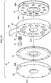
- the clutch mechanism 60 is, as shown in Fig. 15 , configured including a control air chamber member 62, a diaphragm 64, a plate 66 and a pulley 68.
- the control air chamber member 62 is configured with a control air chamber 62A formed with a substantially circular plate shape having a recessed profile along the circumferential direction of the outside face (see Fig. 16 and Fig. 17 ).
- a control air port 62B is pierced as a hole in the outer peripheral face so as to communicate with the control air chamber 62A.
- the compressor CP is connected to the control air port 62B through the switch SW. Compressed air is supplied from the compressor CP into the control air chamber 62A through the control air port 62B when the air supply switch S1 is switched ON and the air discharge switch S2 is switched OFF. Air inside the control air chamber 62A is discharged when the air discharge switch S2 is switched ON and the air supply switch S1 is switched OFF.
- An axial hole 62C is pierced through a central portion of the control air chamber member 62, and the rotation shaft 28 is inserted into the axial hole 62C.
- the diaphragm 64 is bonded to the outside face of the control air chamber member 62 and configures a portion of the wall face of the control air chamber 62A.
- the control air chamber 62A is tightly sealed by the diaphragm 64.
- the diaphragm 64 is configured from a resilient membrane such that the control air chamber 62A is capable of expanding or contracting according to changes in the internal pressure within the control air chamber 62A.
- Each of the plates 66 is a substantially circular plate shape fixed to a leading end portion of each of the lower side sections 14D.
- the plate 66 is disposed at the outside of the diaphragm 64.
- An axial hole 66A is pierced in a central portion of each of the plates 66, and the rotation shafts 28 are inserted into the axial holes 66A.
- Ten individual pin holes 66B are pierced in each of the plates 66 at even intervals around a circumferential direction with the axial hole 66A at the center.
- Each of the pin holes 66B is configured with a step D of slightly reduced diameter D on the pulley 68 side.
- a pin 80 described later, is inserted through each of the pin holes 66B.
- the pulley 68 is formed with a circular plate shape and disposed at the outside face of the plate 66.
- a groove 68A is configured in the outer periphery of the pulley 68.
- a thrust bearing 68C is provided at a central portion of the pulley 68. The thrust bearing 68C is attached to the rotation shafts 28 so as to be capable of relative rotation thereto.
- 11 individual pin holes 68B are pierced in the pulley 68 so as to be arranged in a row along the placement line of the pin holes 66B, with there being a slightly shorter hole separation distance between the pin holes 68B than between the pin holes 66B.
- the pins 80 are inserted from the diaphragm 64 side into each of the pin holes 66B.
- a spring 82 is mounted on the outer periphery of each of the pins 80, with one end of each of the springs 82 making contact with the step D.
- Each of the pins 80 is biased by the spring 82 towards the diaphragm 64 side. Consequently, in a state in which pressing force from the diaphragm 64 is not acting on the pins 80, as shown in Fig.
- the diaphragm 64 is pressed and deformed towards the control air chamber 62A side, such that the leading end portions of the pins 80 are housed inside the plate 66 and the pins 80 do not project out towards the pulley 68 side.
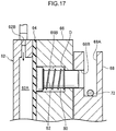
- compressed air is supplied to the control air chamber 62A and the pressure inside the control air chamber 62A is raised, as shown in Fig. 17 , the pins 80 are pressed by the diaphragm 64 towards the pulley 68 side, and the leading ends of the pins 80 project out towards the pulley 68 side.
- a configuration is accordingly achieved in which a very slight amount of rotation of the pulley 68 results in one or other of the pins 80 being inserted into one of the pin holes 68B.
- the control air chamber member 62, the diaphragm 64 and the plate 66 are fixed to each of the rotation shafts 28 so as to be able to rotate together with the rotation shafts 28.
- the pulley 68 is capable of rotation about the rotation shafts 28 in a state in which the pins 80 are not inserted. However the pulley 68 is fixed to the plate 66 so as to rotate together with the rotation shaft 28 when one of the pins 80 is inserted into one of the pin holes 68B.
- the rotation bodies 24 and the coupling frames 52 are attached to the rotation shafts 28 so as to be relatively rotatable with respect to the rotation shafts 28.
- each of the wires 72 extending out from the lower actuators 70 is fixed in the groove 68A of the pulley 68, and wound along the groove 68A.
- the length of the wires 72 is a sufficient length to secure following rotation of the coupling frames 20 in the user forward direction.
- a tension spring 74 formed for example from a torsion spring is attached between the arm 54 and the pulley 68, biasing the pulley 68 in the anticlockwise direction as viewed from the left hand side.
- the slack in the wires 72 is accordingly taken up on the pulley 68, resulting in a state in which pretension has been applied to the lower actuators 70.
- the pretension can enhance the usage efficiency of the actuators by setting to about 5% to 10% of the actuator specification.
- the back frame 14 follows the forward tilting of the user upper body when a user performs a forward bending action and the back frame 14 tilts forwards.
- the air supply switch S1 of the switch SW is switched OFF, and the back frame 14 and the coupling frames 52 rotated relative to each other about the rotation axis S of the joint sections 16.
- the back frame 14 and the coupling frames 52 are uncoupled from each other by the clutch mechanism 60 during such relative rotation, enabling the back frame 14 to freely follow forward tilting.
- a force arising from the tension force F acts to rotate the coupling frames 52 about the rotation axis S in the rotation direction Y, and a force acts to rotate the back frame 14 about the rotation axis S in the rotation direction X, the opposite to that of the coupling frames 52.
- a force acts through the shoulder straps 22 on the upper body of a forward tilted user in the raising rotation direction X.
- a user can accordingly be assisted in an action to raise their upper body.
- the effort required when in a forward tilting posture can also be reduced, enabling a forward tilting posture to be maintained with ease,
- the back frame 14 is rotated in the raising rotation direction X and the upper body of a user can be raised.
- Air supply to the actuators ceases when the air supply switch S1 is switched OFF and the air discharge switch S2 is switched OFF, the air pressure inside the lower actuators 70 and inside the control air chamber 62A ceases to rise, and contraction of the lower actuators 70 stops.
- the back frame 14 stops moving in such a state.
- the upper body of the forward tilting user When the weight of the upper body of the forward tilting user is entrusted to the shoulder straps 22 in this state (the forward tilted upper body is rested against the shoulder straps 22), the upper body adopts a state in which it hangs from the back frame 14. Consequently, the user is able to maintain the forward tilting posture without using the muscles in their lower back (such as the erector spinae). Assistance to maintaining the user forward tilting posture is achieved by maintaining contraction of the actuators 70.
- the pulleys 68 wound with the wires 72 are fixed to the plate 66 during actuation of the lower actuators 70. Unwinding of the wires 72 from the lower actuators 70 is accordingly restricted, and the tension force F can be generated immediately after actuating the lower actuators 70.
- Fig. 18 is a graph illustrating a relationship between contraction percentage and output power for a pneumatic actuator. It is clear from the graph that since output power falls as the contraction percentage of the pneumatic actuators rises, a large load needs to be taken during the initial contraction action in order to employ a pneumatic actuator efficiently.
- any slackness in the wires is removed by the tension spring 74, enabling the tension force F to be generated on the wires 72 immediately after actuation of the lower actuators 70.
- the lower actuators 70 can be employed with good efficiency since the amount of contraction to take up the length of play in the wires 72 is no longer required for the lower actuators 70.
- the clutch mechanisms 60 are provided to generate the tension force F in the wires 72 during actuation of the lower actuators 70, however a similar configuration to that of the clutch mechanism 60 can also be appropriately applied to the actuators 40 side in the first exemplary embodiment.
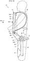
- the back frame 14 is employed as the upper body mounting section mounted to the back of a user, however configuration may be made, as shown in Fig. 19 , with a chest frame 21 for mounting to the chest of a user.
- Fig. 20 to Fig. 22 illustrate a lower back assistance apparatus 90 according to a second example.
- Fig. 20 illustrates the lower back assistance apparatus 90 in a pre-mounted state
- Fig. 21 and Fig. 22 illustrate the lower back assistance apparatus 90 in a state mounted to a user.
- the lower back assistance apparatus 90 includes a back frame 94 serving as an upper body mounting section, shoulder straps 22 serving as front support sections, thigh plates 18 serving as lower limb mounting sections, upper coupling frames 96 serving as coupling sections and coupling frames 52.
- the back frame 94 is mounted to the back of a user and includes a left and right pair of side frame sections 94A, and center frame sections 94B, 94C for coupling together the left and right pair of side frame sections 94A.
- the left and right side frame sections 94A and the center frame section 94B are configured as a single unit.
- the center frame section 94C is disposed so as to couple together intermediate portions of the left and right side frame sections 94A.
- a first joint section 95 is configured at the lower end of each of the left and right side frame sections 94A.
- the back frame 94 and the upper coupling frames 96 are coupled together with the first joint sections 95.
- a waist belt 13 is provided at the front of the first joint sections 95.
- the waist belt 13 is disposed in front of the waist of a user, spanning across between the left and right pair of upper coupling frames 96 so as to couple the upper coupling frames 96 together.
- the upper coupling frames 96 are formed in elongated plate shapes disposed with their length directions along the hips of a user so as to be aligned in the up-down direction.
- the back frame 94 (the left and right side frame sections 94A) is coupled through plates 93, described later, to the upper coupling frames 96 at the upper end sides of the upper coupling frames 96, such that relative rotation of the back frame 94 to the upper coupling frames 96 is possible about a rotation axis S1 running along the user left-right direction.
- the upper coupling frames 96 are configured by rigid members that do not bend even when rotated relative to the back frame 94.
- Second joint sections 97 are configured at the bottom ends of the upper coupling frames 96.
- the upper coupling frames 96 and the coupling frames 52 are coupled together at the second joint sections 97 through a plate 21, described later.
- the upper coupling frames 96 and the coupling frames 52 are coupled together so as to capable of relative rotation with respect to each other about a rotation axis S2 running along the user left-right direction.
- the coupling frames 52 are configured by rigid members that do not bend even when rotated relative to the upper coupling frames 96.
- Thigh plates 18 are fixed to the side of the coupling frames 52 at the other end.
- the thigh plates 18 are disposed in front of the lower limbs of a user.
- each of the first joint sections 95 includes a plate 93 fixed to a lower end portion of the respective left and right side frame sections 94A, a rotation shaft 93S that projects out from the plate 93 towards the shoulder width direction outside (or inside), and a rotation body 93A that is formed in a circular plate shape and is rotatably supported on the rotation shaft 93S.
- the left and right pair of first joint sections 95 are configured so as to be left-right symmetrical to each other.
- the plates 93 are disposed at the sides of the lumbar region of a user, with each of the rotation shafts 93S extending out in a direction from the user lumbar region side towards the shoulder width direction outside.
- Circular holes are formed at the axial center of the rotation bodies 93A for fitting the rotation shafts 93S into such that relative rotation is possible,
- a groove is formed in the peripheral face of each of the rotation bodies 93A to enable the wires 72 to be wrapped around.
- the rotation bodies 93A are fixed to the upper coupling frames 96, such that the upper coupling frames 96 and the rotation bodies 93A are capable of relative rotation with respect to the plates 93 and the back frame 94.
- Stopper members 94D are provided at the upper side of the upper coupling frames 96, on the user rearward side.
- the stopper members 94D project out from the inside of the upper coupling frames 96 along the user left-right direction.
- the stopper members 94D make contact with the plates 93 when the upper coupling frames 96 have rotated in the arrow Y direction together with the back frame 94 rotating in the arrow X direction so as to approach each other to a specific angle.
- the stopper members 94D have a function of preventing rotation exceeding the specific angle.
- Each of the second joint sections 97 includes a plate 21 attached to a portion at the upper end of the coupling frame 52, a rotation shaft 21S that projects out from the plate 21 towards the shoulder width direction outside (or inside), and a rotation body 21A formed in a circular plate shape and rotatably supported on the rotation shaft 21S.
- the left and right pair of second joint sections 97 are configured so as to be left-right symmetrical to each other.
- the plates 21 are placed outside the hip joints of a user and the rotation shafts 21S extend out towards the user shoulder width direction outside.
- Circular holes (not shown in the drawings) are formed at the axial center of the rotation bodies 21A for fitting the rotation shafts 21S into such that relative rotation is possible.
- a groove (not shown in the drawings) is formed in the peripheral face of each of the rotation bodies 21A to enable the wires 72 to be wrapped around.
- the rotation bodies 21A are fixed to the upper coupling frames 96, and the upper coupling frames 96 and the rotation bodies 21A are capable of relative rotation with respect to the plate 21 and the coupling frames 52.
- Stopper members 52D are provided at the lower side of the upper coupling frames 96, on the user rearward side.
- the stopper members 52D project out from the inside of the upper coupling frames 96 along the user left-right direction.
- the stopper members 52D make contact with the plates 21 when the upper coupling frames 96 have rotated in the arrow X direction together with the coupling frames 52 rotating in the arrow Y direction so as to approach each other to a specific angle.
- the stopper members 52D have a function preventing rotation exceeding the specific angle.
- Each of the coupling frames 52 is coupled to the plate 21 through a hinge 21H.
- the hinge 21H enables relative rotation of the coupling frames 52 with respect to the upper coupling frames 96 about a rotation axis S3 disposed in a direction parallel to the body side of a user.
- the coupling frames 52 are accordingly able to follow opening and closing of the thighs of a user.
- a buttock frame section 86 is attached to the upper coupling frames 96.
- the buttock frame section 86 is disposed across from one of the upper coupling frames 96 to the other of the upper coupling frames 96 around the rear of the buttocks of the user.
- a buttock plate 88 is attached at a central portion of the buttock frame section 86 so as to face towards the position of the buttocks of a user.
- Lower actuators 70 are provided to the lower back assistance apparatus 90.
- the lower actuators 70 are disposed at the coupling frames 52 side, similarly to in the first exemplary embodiment.
- Wires 72 are attached to the upper end side of the lower actuators 70. Portions at one end of the wires 72 project out from the upper end of the lower actuators 70, are wrapped around the rotation bodies 21A, are wrapped around the rotation bodies 93A via clutch sections 100, described later, and are fixed in grooves of the respective rotation bodies 93A.
- the clutch sections 100 are provided to the upper coupling frames 96, and each includes a double block section 102, a piston section 104, a cylinder section 106, and a lock section 108.
- the cylinder section 106 is fixed to a central portion of the upper coupling frame 96 on the user rearward side.
- the lock section 108 is disposed inside the cylinder section 106 and has a lock hole 108A provided in the center.
- the piston section 104 is inserted into the lock hole 108A.
- Each of the piston sections 104 is disposed along a direction cutting across between the rotation bodies 93A and the rotation bodies 21A, and movement along this direction is possible when the clutch sections 100 are not actuated.
- the double block section 102 is attached through a support plate 103 to the leading end side of the piston section 104 such that two individual blocks 102K straddle the piston section 104.
- the double block section 102 is capable of moving together with the piston section 104.
- Each of the wires 72 is wrapped around both of the respective two individual blocks 102K so as to span between the two.
- a coil spring 105 is disposed between the support plate 103 and the cylinder section 106 of the piston section 104. Each of the piston sections 104 is biased towards the user forward direction by the coil spring 105.
- the wires 72 are accordingly entrained without slack around the rotation bodies 21 A, the blocks 102K and the rotation bodies 93A.
- the piston section 104 is free to move inside the lock hole 108A when the actuators 40 are not being actuated, enabling movement along the user front-rear direction.
- the lock section 108 is tilted by controlling the air pressure in the space either to the right or left of the lock section 108, and a one-way check function of the lock section 108 is exhibited. Control is accordingly achieved in which movement is possible in the direction towards the user front (the direction to remove wire slack) but movement in the reverse direction is not possible.
- the compressor CP is connected to the lower actuators 70 through the switch SW.
- the switch SW is also connected to the clutch sections 100.
- Compressed air is supplied from the compressor CP to the lower actuators 70 when the air supply switch S1 is switched ON and the air discharge switch S2 is switched OFF, and the one-way check function of the clutch sections 100 is switched ON. Air inside the lower actuators 70 is discharged and the one-way check function of the clutch sections 100 is switched OFF when the air discharge switch S2 is switched ON and the air supply switch S1 is switched OFF.
- a switch may be independently provided for controlling air to the clutch sections 100.
- the back frame 94 follows forward tilting of the upper body of the user when a user performs a forward bending action, and the back frame 94 tilts forward.
- the air supply switch S1 of the switch SW is switched OFF, and the back frame 94 and the upper coupling frames 96 rotate relative to each other about the rotation axis S1 of the first joint sections 95.
- the upper coupling frames 96 and the coupling frames 52 also rotate relative to each other about the rotation axis S2 of the second joint sections 97.
- each of the clutch sections 100 is able to move so as to retreat towards the rear (move towards the user rearwards direction), and the wires 72 are payed out, enabling the back frame 94 to freely follow the forward tilting (see Fig. 23 ).
- Air ceases to be supplied into the actuators when the air supply switch S1 is switched OFF and the air discharge switch S2 is switched OFF, such that the air pressure within the lower actuators 70 ceases to rise and contraction of the lower actuators 70 stops.
- the back frame 94 accordingly stops in such a state.
- the upper body of the forward tilting user When the weight of the upper body of the forward tilting user is entrusted to the shoulder straps 22 in this state (the forward tilted upper body is rested against the shoulder straps 22), the upper body adopts a state in which it hangs from the back frame 94. Consequently, the user is able to maintain the forward tilting posture without using the muscles in their lower back (such as the erector spinae). By maintaining contraction of the actuators 70 assistance to maintaining the user forward tilting posture is achieved.
- the tension force F to the wires 72 can be generated immediately after actuation of the lower actuators 70 due to provision of the clutch sections 100.
- the lower actuators 70 can be efficiently employed since contraction is not required in the lower actuators 70 to take up a length of play in the wires 72.
- a back frame 94 mounted to the back of a user is employed as the upper body mounting section, however configuration may be made, as shown in Fig. 26 , in which a chest frame 94F is employed for mounting to the chest of a user.
- each of the upper coupling frames 96 may be formed with an arm 110 that is rotatably supported by a shaft, a block 102K fixed to the arm 110 that has a saw-tooth profile on the end face, and a guide groove 112 formed in each of the upper coupling frames 96 along the path of the block 102K.
- a first and second end of each of the coil springs 105 is respectively anchored to the upper coupling frames 96 and the arm 110.
- the saw-tooth end face profiled arm 110 meshes with an arm 113 having a ratchet pawl, thereby connecting the arm 113 to an air cylinder 114,
- the purpose of such a structure is to enable free movement for the person to whom a lower back assistance apparatus is mounted, and also wires are taut when bending forward to lift up an object, and wires are slack when standing upright.
- the ratchet mechanism is released when air is injected into an air cylinder and the air cylinder actuated, enabling movement along the guide groove 112, such that a function is exhibited preventing the wires from becoming slack or becoming detached by a certain force being applied to each of the wires.
- Air is supplied into the actuators 40 on actuation to provide lower back assistance for a user lifting an object, and the actuators 40 contract so as to generate a force pulling the wires in a raising direction. Air is let out of the air cylinder 114 at the same time. Consequently, as shown in Fig. 27A and Fig.
Landscapes
- Health & Medical Sciences (AREA)
- Animal Behavior & Ethology (AREA)
- Veterinary Medicine (AREA)
- Engineering & Computer Science (AREA)
- Biomedical Technology (AREA)
- Heart & Thoracic Surgery (AREA)
- Vascular Medicine (AREA)
- Orthopedic Medicine & Surgery (AREA)
- General Health & Medical Sciences (AREA)
- Life Sciences & Earth Sciences (AREA)
- Public Health (AREA)
- Nursing (AREA)
- Manipulator (AREA)
- Orthopedics, Nursing, And Contraception (AREA)
- Rehabilitation Tools (AREA)
- Prostheses (AREA)
Description
- The present invention relates to a lower back assistance apparatus.
- Assistance apparatuses are known for assisting forward bending action of the upper body of a user. For example, in Japanese Patent Laid-Open No.
2009-011818 - The lower back assistance apparatus of
JP-A No. 2009-011818
JP 2003 265548 claim 1. Related apparatuses are given inJP 2009 011818 DE 10 2004 008509FR 2 864 891US 2008/161738 . - In consideration of the above circumstances, an object of the present invention is to provide a lower back assistance apparatus that is able to stabilize and assist forward bending actions of a user mounted with the lower back assistance apparatus.
- A lower back assistance apparatus according to the present invention is defined in
claim 1. Preferred embodiments are defined in the dependent claims. - According to the present invention as described above, the forward tilting posture of a user can be stabilized and assisted when mounted with the lower back assistance apparatus.
-
-
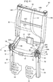
Fig. 1 is a perspective view illustrating a lower back assistance apparatus according to a first example. -
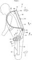
Fig. 2 is a side view illustrating a state of use of a lower back assistance apparatus according to the first example. -
Fig. 3 is a side view illustrating a state of use of a lower back assistance apparatus according to the first example. -
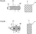
Fig. 4a is a drawing schematically showing an actuator provided to a lower back assistance apparatus according to the first example. -
Fig. 4b is a drawing schematically showing an actuator provided to a lower back assistance apparatus according to the first example. -
Fig. 5 is a drawing schematically showing an actuator air supply and discharge mechanism provided to a lower back assistance apparatus according to the first example. -
Fig. 6 is a schematic explanatory diagram of a lower back assistance apparatus according to the first example. -
Fig. 7 is a schematic explanatory diagram of a modified example of a lower back assistance apparatus according to the first example. -
Fig. 8 is a schematic explanatory diagram of a different modified example of a lower back assistance apparatus according to the first example. -
Fig. 9 is a schematic explanatory diagram of a different modified example of a lower back assistance apparatus according to the first example. -
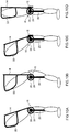
Fig. 10A is an explanatory diagram explaining the action of a lower back assistance apparatus according to the first example from which the lumbar frame section has been removed. -
Fig. 10B is an explanatory diagram explaining the action of a lower back assistance apparatus according to the first example from which the lumbar frame section has been removed. -
Fig, 10C is an explanatory diagram explaining the action of a lower back assistance apparatus according to the first example. -
Fig. 10D is an explanatory diagram explaining the action of a lower back assistance apparatus according to the first example. -
Fig. 11 is a perspective view of a lower back assistance apparatus according to a first exemplary embodiment of the present invention. -
Fig. 12 is a side view illustrating a state of use of a lower back assistance apparatus according to the first exemplary embodiment of the present invention. -
Fig. 13 is a side view illustrating a state of use of a lower back assistance apparatus according to the first exemplary embodiment of the present invention. -
Fig. 14 is a drawing schematically showing an actuator air supply and discharge mechanism provided to a lower back assistance apparatus according to the first exemplary embodiment of the present invention. -
Fig. 15 is an exploded perspective view showing a clutch mechanism of a lower back assistance apparatus according to the first exemplary embodiment of the present invention. -
Fig. 16 is a cross section showing a clutch mechanism of a lower back assistance apparatus according to the first exemplary embodiment of the present invention in a state in which a pulley is not fixed to a plate. -
Fig. 17 is a cross section showing a clutch mechanism of a lower back assistance apparatus according to the first exemplary embodiment of the present invention in a state in which a pulley is fixed to a plate. -
Fig. 18 is a graph showing a relationship between the contraction percentage and output of a pneumatic actuator. -
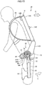
Fig. 19 is a side view illustrating a state of use of a lower back assistance apparatus according to a modified example of the first example and the first exemplary embodiment of the present invention. -
Fig. 20 is a perspective view of a lower back assistance apparatus according to a second example. -
Fig. 21 is a side view illustrating a state of use of a lower back assistance apparatus according to the second example. -
Fig. 22 is a side view illustrating a state of use of a lower back assistance apparatus according to the second example. -
Fig. 23 is an expanded drawing of the vicinity of a clutch section according to the second example. -
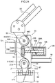
Fig. 24 is an expanded drawing of the vicinity of a clutch section according to the second example. -
Fig. 25 is a drawing schematically showing an actuator air supply and discharge mechanism provided to a lower back assistance apparatus according to the second example. -
Fig. 26 is a side view illustrating a state of use of a lower back assistance apparatus according to a modified example of the second example. -
Fig. 27A is an expanded drawing of the vicinity of anupper coupling frame 96 according to a modified example of the second example. -
Fig. 27B is an expanded drawing of the vicinity of theupper coupling frame 96 according to a modified example of the second example. -
Fig. 27C is an expanded drawing of the vicinity of theupper coupling frame 96 according to a modified example of the second example. - Detailed explanation follows regarding a first example, with reference to the drawings. For ease of explanation the front side is taken as the arrow FR direction in the drawings, indicating the front direction side for a user, and up, down, left and right are directions based on facing towards the front side direction.
- A lower
back assistance apparatus 10 according to the first example is illustrated inFig. 1 to Fig. 3 .Fig. 1 illustrates the lowerback assistance apparatus 10 in a pre-mounted state, andFig. 2 andFig. 3 illustrate the lowerback assistance apparatus 10 in a state mounted to a user. As shown in these drawings, the lowerback assistance apparatus 10 includes aback frame 14 serving as an upper body mounting section,shoulder straps 22 serving as front support sections,thigh plates 18 serving as lower limb mounting sections andcoupling frames 20 serving as coupling sections. - The
back frame 14 is mounted to the back of a user and includes a left and right pair ofside frame sections 14A, andcenter frame sections side frame sections 14A. The left and right pair ofside frame sections 14A is configured so as to be left-right symmetrical to each other. - The
side frame sections 14A are formed by elongated tubes, and are disposed separated from each other aligned along the top-bottom direction of the back of a user.Lower side sections 14D are coupled and fixed to the bottom ends of theside frame sections 14A. Thelower side sections 14D extend diagonally forwards out from the bottom ends of each of the left and right pair ofside frame sections 14A, and are disposed at both the left and right edges of the lumbar region of a user. - The
center frame section 14B is disposed so as to be connected to the top ends of the left and right pair ofside frame sections 14A, and thecenter frame section 14C is disposed so as to be connected to an intermediate portion on each of the left and right pair ofside frame sections 14A. - A
lumbar frame section 12 serving as a lumbar mounting section is provided to thelower side sections 14D. Thelumbar frame section 12 is disposed substantially parallel to thecenter frame section 14B so as to span across between the left and right pair oflower side sections 14D. Alumbar plate 12A is attached at the center of thelumbar frame section 12. Theback frame 14 and the coupling frames 20 are coupled together byjoint sections 16 provided at both the leading ends of the C-shapedlumbar frame section 12, such that theback frame 14 and the coupling frames 20 are able to rotate relative to each other. - A
block 44 is configured at the upper end of each of thelower side sections 14D. Awire 42, described later, is wrapped around each of theblocks 44, and theblocks 44 guide the direction of thewires 42 from the back face side of a user out diagonally forwards. - The shoulder straps 22 are attached to the
side frame sections 14A. The shoulder straps 22 are provided in a left and right pair, and one end of each of the shoulder straps 22 is attached towards the center of thecenter frame section 14B, and the other end of the shoulder straps 22 is attached to the lower end portion of the respectiveside frame section 14A. The left and right pair ofshoulder straps 22 are each linked together by abelt 22A at central portions of the shoulder straps 22. The shoulder straps 22 are tightly fitted to the upper body of a user such that theback frame 14 does not slip. - The
joint sections 16 are configured at the lower ends of thelower side sections 14D. The coupling frames 20 and the back frame 14 (thelower side sections 14D) are coupled together by thejoint sections 16. Awaist belt 13 is provided to the fronts of thejoint sections 16. Thewaist belt 13 is disposed in front of the waist of a user, spanning across between the left and right pair ofjoint sections 16 so as to couple together thejoint sections 16. Further details regarding thejoint sections 16 are described later. - The coupling frames 20 are formed in an elongated shape and are disposed along the lower limbs of the user. One end (the top end) of each of the coupling frames 20 is coupled to the
lower side section 14D using thejoint section 16. Thelower side sections 14D and the coupling frames 20 are coupled together so as to be rotatable relative to each other about a rotation axis S disposed along the user left-right direction. The coupling frames 20 are configured by rigid members that do not bend even when rotated relative to theback frame 14. -
Thigh plates 18 are fixed to the side of the coupling frames 20 at the other end. Thethigh plates 18 are formed in a curved shape to cover the front of the lower limbs of a user. Thethigh plates 18 are disposed at the front of the lower limbs of a user. - Each of the
joint sections 16 includes aplate 26 fixed to a portion at the lower end of thelower side section 14D, arotation shaft 28 that projects out from theplate 26 towards the shoulder width direction outside, and a circular plate shapedrotation body 24 that is rotatably supported on therotation shaft 28.End portions 12B are disposed at the two ends of thelumbar frame section 12. The left and right pair ofjoint sections 16 are configured so as to be left-right symmetrical to each other. - The
plates 26 are positioned at the sides of the lumbar region of a user, and therotation shafts 28 extend out in a direction from the sides of the user lumbar region towards the shoulder width direction outside. A circular hole (not shown in the drawings) is formed at the axial center of therotation bodies 24 for therotation shafts 28 to fit into and allow relative rotation.Grooves 24A are formed in the peripheral faces of therotation bodies 24 to enable thewires 42 to be wrapped around, as described later. It is not essential for therotation bodies 24 to have a circular shape, and configuration may be made with a semi-circular plate shape or an elliptical plate shape. - The two
end portions 12B of thelumbar frame section 12 are disposed at the inside of theplates 26. The twoend portions 12B are attached so as to be capable of rotating about therotation shafts 28. - One end of each of the coupling frames 20 is fixed to the
respective rotation body 24, such that the coupling frames 20 are capable of rotating together with therotation bodies 24. When theplates 26 rotate in the anticlockwise direction with respect torotation bodies 24 as viewed from the left hand side, theback frame 14 swings in the same direction. When theplates 26 rotate with respect to therotation bodies 24 in the clockwise direction as viewed from the left hand side, theback frame 14 also swings in the same direction. - When this occurs, the position of the coupling frames 20 is restricted to a position along the lower limbs of a user due to the
thigh plates 18 being in contact from the front with the user's lower limbs. Relative rotation between theback frame 14 and the coupling frames 20 therefore occurs about therotation shafts 28 of thejoint sections 16. -
Actuators 40 are provided to the lowerback assistance apparatus 10. Theactuators 40 are housed inside the respective pair ofside frame sections 14A of theback frame 14. Theactuators 40 are pneumatic actuators (fluid pressure actuators, called McKibben Artificial Muscles). As illustrated inFig. 4A and Fig. 4B , a pneumatic actuator AC includes an inner tube IC of an expandable and contractible body, and a mesh sleeve MS that is a covering body of mesh form for covering the inner tube IC. The mesh sleeve MS is for example configured from a non-extendible thread member such as a high tensile strength fiber. The two end portions in the length (axial) direction of the mesh sleeve MS are fixed to the two length direction end portions of the inner tube IC. - As shown in
Fig. 4B , the inner tube IC is expanded by air being supplied into the inner tube IC. Expansion of the inner tube IC is converted by the mesh sleeve MS into a contraction in the overall length of the pneumatic actuator AC. Namely, when the air is supplied into the pneumatic actuator AC the length of the pneumatic actuator AC contracts as its diameter is expanding. Due to such contraction in length, a force F is generated towards the direction of contraction of the pneumatic actuator AC. - As shown in
Fig. 5 , a compressor CP is connected through a switch SW to theactuators 40. The switch SW is provided with an air supply switch S1 and an air discharge switch S2. Compressed air is supplied from the compressor CP to theactuators 40 when the air supply switch S1 is switched ON and the air discharge switch S2 is switched OFF. Air inside theactuators 40 is discharged when the air discharge switch S2 is switched ON and the air supply switch S1 is switched OFF. - As shown in
Fig. 1 to Fig. 3 , thewire 42 is attached to the lower end side of theactuators 40, One end portion of each of thewires 42 extends out from the lower end of theactuators 40, changes direction as it is wrapped around theblock 44 and is fixed in thegroove 24A of therotation body 24. - With the
actuators 40 at their natural length (maximum length), thewires 42 are wrapped around therotation bodies 24 with at least slack of the amount of increase in length when theback frame 14 tilts forward in the permissible range, namely thewires 42 are fixed to therotation bodies 24 when theback frame 14 has been tilted forward. -
Fig. 6 is a simplified explanatory diagram of the lowerback assistance apparatus 10 of the present example.Fig. 6 illustrates a state in which theactuators 40 have been actuated with theback frame 14 in a forward tilted state. - Explanation follows regarding operation of the present example.
- When a user is performing a specific operation with their upper body in a forward tilted posture, such as a welding operation, if a forward bending action is performed then the
back frame 14 tilts forwards to follow the forward tilting of the upper body of a user. When this occurs theback frame 14 rotates relative to the coupling frames 20 about the rotation axis S of thejoint sections 16. The coupling frames 20 are restricted to a position aligned along the lower limbs of the user by thethigh plates 18. - When the air supply switch S1 of the switch SW is switched ON and the air discharge switch S2 of the switch SW is switched OFF with the
back frame 14 in a forward tilted state, air supply to theactuators 40 is performed and theactuators 40 contract. - The
actuators 40 contract, and partway through contraction reach a state in which there is no play left in thewires 42, with tension force F (seeFig. 3 andFig. 6 ) then generated. A rotation force accordingly acts on the coupling frames 20 towards direction Y. However, the coupling frames 20 are unable to rotate in the Y direction due to being restricted by thethigh plates 18. The contraction of theactuators 40 is accordingly expressed by a rotation of theback frame 14 in the X direction. The action of a user to raise their upper body can accordingly be assisted since force acts through the shoulder straps 22 on the upper body of the forward tilted user in the raising rotation direction X. Due to force in the raising rotation direction X becoming greater than tilting force on a user towards the front, theback frame 14 is rotated towards the raising rotation direction X, and the upper body of a user can be raised. - If the air supply switch S1 of the switch SW is then switched OFF and the air discharge switch S2 of the switch SW is switched ON, air stops being supplied to the
actuators 40, air pressure in theactuators 40 stops rising, and contraction of theactuators 40 stops. The rotation of theback frame 14 towards the X direction stops in this state. - When the weight of the upper body of the forward tilting user is entrusted to the shoulder straps 22 in this state (the forward tilted upper body is rested against the shoulder straps 22), the upper body adopts a state in which it hangs from the
back frame 14. Consequently, the user is able to maintain the forward tilting posture without using the muscles in their lower back (such as the erector spinae). By maintaining contraction of theactuators 40 assistance to maintaining the user forward tilting posture is achieved. - Since the
rotation bodies 24 are rotatable in the clockwise rotation direction as viewed from the left hand side irrespective of whether theactuators 40 are in a compressed state or not, a user is able at will to raise their upper body to an upright posture from a forward tilting posture. - According to the present example, the coupling frames 20 that are formed from rigid members that have been coupled to the
thigh plates 18 and maintain a non-bent state, and so the rotation force (about the rotation axis S) in the opposite direction to force on theback frame 14 can be readily made to act on the coupling frames 20 when theactuators 40 are actuated. Rotation force (reaction force) of the coupling frames 20 can accordingly be employed as a force stably acting as a force on theback frame 14 for rotation in the raising rotation direction X. - In the present example the
actuators 40 are each respectively disposed in the pair ofside frame sections 14A, however configuration may be made in which asingle actuator 40 is disposed only in one of theside frame sections 14A. - The
actuators 40 in the present example are disposed in the up-down direction along theside frame sections 14A. However, as shown inFig. 7 , theactuators 40 may be disposed in a transverse direction along thecenter frame section 14C. A force can also be caused to act to rotate theback frame 14 in the raising rotation direction X in such cases, similarly to as shown inFig. 6 . - Furthermore, while explanation in the present example is of an example in which the
actuators 40 are mounted to theback frame 14, configuration may be made with theactuators 40 disposed on the coupling frames 20 side, as shown inFig. 8 . In such cases thewires 42 are fixed at theplate 26 side. Also in cases in which theactuators 40 are disposed at thecoupling frame 20 side, force arising from the tension force F can be made to act on theback frame 14 in the raising rotation direction X, and force can be made to act on the coupling frames 20 in rotation direction Y, the opposite direction force on theback frame 14. A reduction can accordingly be achieved in the strain on a user when tilting forward, and maintaining a forward tilting posture and action to raise the upper body can be stabilized and assisted. - The
actuators 40 may also be disposed, as shown inFig. 9 , to both theback frame 14 and the coupling frames 20. - In the present example a single pneumatic actuator is employed for each
single actuator 40, however configuration may be made with plural pneumatic actuators therefor depending on the assisting force required. Insuch cases wires 42 corresponding to the number of pneumatic actuators are fixed to therotation bodies 24. - The
lumbar frame section 12 is provided in the present example, However thelumbar frame section 12 is not always required. In particular, movement of theback frame 14 towards the user front side when theactuators 40 are actuated can be prevented by provision of thelumbar frame section 12, Namely, in cases in which thelumbar frame section 12 is not provided, when theactuators 40 are actuated in the forward tilted state as shown inFig. 10A , thejoint sections 16 move forward as shown inFig. 10B , rendering it difficult for the force to act in the user raising direction. However, when thelumbar frame section 12 is provided, when theactuators 40 are actuated in the forward tilted state shown inFig. 10C , forward movement of thejoint sections 16 is restricted by thelumbar frame section 12, as shown inFig, 10D , and force can be efficiently made to act in the direction to raise a user, enabling more stable assistance to be given to a user. In place of thelumbar frame section 12, configuration may also be made with thewaist belt 13 not only disposed in front of but also behind thejoint sections 16, so as to fix thejoint sections 16 with the waist belt to the hip joint location of the user. - In the present example the
thigh plates 18 are configured in a shape covering only the front side of the lower limbs of the user, however thethigh plates 18 may be configured to cover around the whole periphery of the lower limbs of the user. In particular, complicated mounting can be avoided by only covering the front, and user wearing comfort can be enhanced compared to when configuration is made covering around the whole of the periphery. - Explanation follows regarding the first exemplary embodiment of the present invention. Parts of the configuration similar to those of the first example are allocated the same reference numerals and detailed explanation thereof is omitted.
- A lower
back assistance apparatus 50 of the present exemplary embodiment differs from the first example in that the actuators are disposed on thecoupling frame 20 side,Joint sections 16 also differ from those of the first example in that they are provided with a clutch mechanism. - As shown in
Fig. 11 to Fig. 13 , coupling frames 52 are formed from elongated tubes disposed along the lower limbs of a user. A portion at one end of each of the coupling frames 52 is rotatably attached torotation shafts 28 through anarm 54, and coupled to alower side section 14D. A thigh plate 18A is attached to a portion at the other end of each of the coupling frames 52. Alower actuator 70 is housed inside the tube of each of the coupling frames 52. The configuration of thelower actuators 70 themselves is similar to theactuators 40. As shown inFig. 14 , a compressor CP is connected to thelower actuators 70 through a switch SW Compressed air is supplied from the compressor CP to thelower actuators 70 when an air supply switch S1 is switched ON and an air discharge switch S2 is switched OFF. Air is discharged from inside thelower actuators 70 when the air discharge switch S2 is switched ON and the air supply switch S1 is switched OFF. -
Wires 72 of thelower actuators 70 extend out from the upper end side of thelower actuators 70, and one end of each of thewires 72 is fixed to apulley 68, described later. - A
clutch mechanism 60 is configured to each of left and rightjoint sections 16. Theclutch mechanism 60 is, as shown inFig. 15 , configured including a controlair chamber member 62, adiaphragm 64, aplate 66 and apulley 68. - The control
air chamber member 62 is configured with acontrol air chamber 62A formed with a substantially circular plate shape having a recessed profile along the circumferential direction of the outside face (seeFig. 16 andFig. 17 ). Acontrol air port 62B is pierced as a hole in the outer peripheral face so as to communicate with thecontrol air chamber 62A. The compressor CP is connected to thecontrol air port 62B through the switch SW. Compressed air is supplied from the compressor CP into thecontrol air chamber 62A through thecontrol air port 62B when the air supply switch S1 is switched ON and the air discharge switch S2 is switched OFF. Air inside thecontrol air chamber 62A is discharged when the air discharge switch S2 is switched ON and the air supply switch S1 is switched OFF. Anaxial hole 62C is pierced through a central portion of the controlair chamber member 62, and therotation shaft 28 is inserted into theaxial hole 62C. - The
diaphragm 64 is bonded to the outside face of the controlair chamber member 62 and configures a portion of the wall face of thecontrol air chamber 62A. Thecontrol air chamber 62A is tightly sealed by thediaphragm 64. Thediaphragm 64 is configured from a resilient membrane such that thecontrol air chamber 62A is capable of expanding or contracting according to changes in the internal pressure within thecontrol air chamber 62A. - Each of the
plates 66 is a substantially circular plate shape fixed to a leading end portion of each of thelower side sections 14D. Theplate 66 is disposed at the outside of thediaphragm 64. Anaxial hole 66A is pierced in a central portion of each of theplates 66, and therotation shafts 28 are inserted into theaxial holes 66A. Ten individual pin holes 66B are pierced in each of theplates 66 at even intervals around a circumferential direction with theaxial hole 66A at the center. Each of the pin holes 66B is configured with a step D of slightly reduced diameter D on thepulley 68 side. Apin 80, described later, is inserted through each of the pin holes 66B. - The
pulley 68 is formed with a circular plate shape and disposed at the outside face of theplate 66. Agroove 68A is configured in the outer periphery of thepulley 68. A thrust bearing 68C is provided at a central portion of thepulley 68. The thrust bearing 68C is attached to therotation shafts 28 so as to be capable of relative rotation thereto. 11 individual pin holes 68B are pierced in thepulley 68 so as to be arranged in a row along the placement line of the pin holes 66B, with there being a slightly shorter hole separation distance between the pin holes 68B than between the pin holes 66B. - The
pins 80 are inserted from thediaphragm 64 side into each of the pin holes 66B. As shown inFig. 16 , aspring 82 is mounted on the outer periphery of each of thepins 80, with one end of each of thesprings 82 making contact with the step D. Each of thepins 80 is biased by thespring 82 towards thediaphragm 64 side. Consequently, in a state in which pressing force from thediaphragm 64 is not acting on thepins 80, as shown inFig. 16 , thediaphragm 64 is pressed and deformed towards thecontrol air chamber 62A side, such that the leading end portions of thepins 80 are housed inside theplate 66 and thepins 80 do not project out towards thepulley 68 side. When compressed air is supplied to thecontrol air chamber 62A and the pressure inside thecontrol air chamber 62A is raised, as shown inFig. 17 , thepins 80 are pressed by thediaphragm 64 towards thepulley 68 side, and the leading ends of thepins 80 project out towards thepulley 68 side. A configuration is accordingly achieved in which a very slight amount of rotation of thepulley 68 results in one or other of thepins 80 being inserted into one of the pin holes 68B. - The control
air chamber member 62, thediaphragm 64 and theplate 66 are fixed to each of therotation shafts 28 so as to be able to rotate together with therotation shafts 28. Thepulley 68 is capable of rotation about therotation shafts 28 in a state in which thepins 80 are not inserted. However thepulley 68 is fixed to theplate 66 so as to rotate together with therotation shaft 28 when one of thepins 80 is inserted into one of the pin holes 68B. Therotation bodies 24 and the coupling frames 52 are attached to therotation shafts 28 so as to be relatively rotatable with respect to therotation shafts 28. - The end portion of each of the
wires 72 extending out from thelower actuators 70 is fixed in thegroove 68A of thepulley 68, and wound along thegroove 68A. The length of thewires 72 is a sufficient length to secure following rotation of the coupling frames 20 in the user forward direction. Atension spring 74 formed for example from a torsion spring is attached between thearm 54 and thepulley 68, biasing thepulley 68 in the anticlockwise direction as viewed from the left hand side. The slack in thewires 72 is accordingly taken up on thepulley 68, resulting in a state in which pretension has been applied to thelower actuators 70. The pretension can enhance the usage efficiency of the actuators by setting to about 5% to 10% of the actuator specification. - Explanation follows regarding operation of the present exemplary embodiment. The
back frame 14 follows the forward tilting of the user upper body when a user performs a forward bending action and theback frame 14 tilts forwards. When this occurs the air supply switch S1 of the switch SW is switched OFF, and theback frame 14 and the coupling frames 52 rotated relative to each other about the rotation axis S of thejoint sections 16. Theback frame 14 and the coupling frames 52 are uncoupled from each other by theclutch mechanism 60 during such relative rotation, enabling theback frame 14 to freely follow forward tilting. - In the forward tilted state of the
back frame 14, air is supplied to thelower actuators 70 and to thecontrol air chamber 62A when the air supply switch S1 is switched ON and the air discharge switch S2 is switched OFF. Thelower actuators 70 accordingly contract. A high internal pressure of thecontrol air chamber 62A is achieved, and thediaphragm 64 deforms from the state illustrated inFig. 16 to the state illustrated inFig. 17 , such that one of thepins 80 is inserted into one of the pin holes 68B of thepulley 68. Thepulley 68 is accordingly fixed to theplate 66 and unwinding of thewires 72 is restricted. Accordingly, due to combination with the action of thetension spring 74, thelower actuators 70 are capable of generating tension force F on thewires 72 from the time of contraction initiation. - A force arising from the tension force F acts to rotate the coupling frames 52 about the rotation axis S in the rotation direction Y, and a force acts to rotate the
back frame 14 about the rotation axis S in the rotation direction X, the opposite to that of the coupling frames 52. When this occurs a force acts through the shoulder straps 22 on the upper body of a forward tilted user in the raising rotation direction X. A user can accordingly be assisted in an action to raise their upper body. The effort required when in a forward tilting posture can also be reduced, enabling a forward tilting posture to be maintained with ease, When the force in the raising rotation direction X becomes larger than the force tilting a user forwards, theback frame 14 is rotated in the raising rotation direction X and the upper body of a user can be raised. - Air supply to the actuators ceases when the air supply switch S1 is switched OFF and the air discharge switch S2 is switched OFF, the air pressure inside the
lower actuators 70 and inside thecontrol air chamber 62A ceases to rise, and contraction of thelower actuators 70 stops. Theback frame 14 stops moving in such a state. - When the weight of the upper body of the forward tilting user is entrusted to the shoulder straps 22 in this state (the forward tilted upper body is rested against the shoulder straps 22), the upper body adopts a state in which it hangs from the
back frame 14. Consequently, the user is able to maintain the forward tilting posture without using the muscles in their lower back (such as the erector spinae). Assistance to maintaining the user forward tilting posture is achieved by maintaining contraction of theactuators 70. - According to the present exemplary embodiment, due to provision of the
clutch mechanisms 60 including the tension springs 74, thepulleys 68 wound with thewires 72 are fixed to theplate 66 during actuation of thelower actuators 70. Unwinding of thewires 72 from thelower actuators 70 is accordingly restricted, and the tension force F can be generated immediately after actuating thelower actuators 70. - Explanation follows regarding action characteristics of general pneumatic actuators.
Fig. 18 is a graph illustrating a relationship between contraction percentage and output power for a pneumatic actuator. It is clear from the graph that since output power falls as the contraction percentage of the pneumatic actuators rises, a large load needs to be taken during the initial contraction action in order to employ a pneumatic actuator efficiently. - In the present exemplary embodiment, as explained above, any slackness in the wires is removed by the
tension spring 74, enabling the tension force F to be generated on thewires 72 immediately after actuation of thelower actuators 70. Hence, thelower actuators 70 can be employed with good efficiency since the amount of contraction to take up the length of play in thewires 72 is no longer required for thelower actuators 70. - In the present exemplary embodiment, the
clutch mechanisms 60 are provided to generate the tension force F in thewires 72 during actuation of thelower actuators 70, however a similar configuration to that of theclutch mechanism 60 can also be appropriately applied to theactuators 40 side in the first exemplary embodiment. - In the first example and the first exemplary embodiment described above the
back frame 14 is employed as the upper body mounting section mounted to the back of a user, however configuration may be made, as shown inFig. 19 , with achest frame 21 for mounting to the chest of a user. - Explanation follows regarding a second example. Parts of the configuration similar to those of the first example and the first exemplary embodiment are allocated the same reference numerals and detailed explanation thereof is omitted.
-
Fig. 20 to Fig. 22 illustrate a lowerback assistance apparatus 90 according to a second example.Fig. 20 illustrates the lowerback assistance apparatus 90 in a pre-mounted state, andFig. 21 andFig. 22 illustrate the lowerback assistance apparatus 90 in a state mounted to a user. As shown in these drawings, the lowerback assistance apparatus 90 includes aback frame 94 serving as an upper body mounting section,shoulder straps 22 serving as front support sections,thigh plates 18 serving as lower limb mounting sections, upper coupling frames 96 serving as coupling sections and coupling frames 52. - The
back frame 94 is mounted to the back of a user and includes a left and right pair ofside frame sections 94A, andcenter frame sections side frame sections 94A. The left and rightside frame sections 94A and thecenter frame section 94B are configured as a single unit. Thecenter frame section 94C is disposed so as to couple together intermediate portions of the left and rightside frame sections 94A. - A first
joint section 95 is configured at the lower end of each of the left and rightside frame sections 94A. Theback frame 94 and the upper coupling frames 96 are coupled together with the firstjoint sections 95. Awaist belt 13 is provided at the front of the firstjoint sections 95. Thewaist belt 13 is disposed in front of the waist of a user, spanning across between the left and right pair of upper coupling frames 96 so as to couple the upper coupling frames 96 together. - The upper coupling frames 96 are formed in elongated plate shapes disposed with their length directions along the hips of a user so as to be aligned in the up-down direction. The back frame 94 (the left and right
side frame sections 94A) is coupled throughplates 93, described later, to the upper coupling frames 96 at the upper end sides of the upper coupling frames 96, such that relative rotation of theback frame 94 to the upper coupling frames 96 is possible about a rotation axis S1 running along the user left-right direction. The upper coupling frames 96 are configured by rigid members that do not bend even when rotated relative to theback frame 94. - Second
joint sections 97 are configured at the bottom ends of the upper coupling frames 96. The upper coupling frames 96 and the coupling frames 52 are coupled together at the secondjoint sections 97 through aplate 21, described later. The upper coupling frames 96 and the coupling frames 52 are coupled together so as to capable of relative rotation with respect to each other about a rotation axis S2 running along the user left-right direction. The coupling frames 52 are configured by rigid members that do not bend even when rotated relative to the upper coupling frames 96. -
Thigh plates 18 are fixed to the side of the coupling frames 52 at the other end. Thethigh plates 18 are disposed in front of the lower limbs of a user. - As shown in
Fig. 22 andFig. 23 , each of the firstjoint sections 95 includes aplate 93 fixed to a lower end portion of the respective left and rightside frame sections 94A, arotation shaft 93S that projects out from theplate 93 towards the shoulder width direction outside (or inside), and arotation body 93A that is formed in a circular plate shape and is rotatably supported on therotation shaft 93S. The left and right pair of firstjoint sections 95 are configured so as to be left-right symmetrical to each other. - The
plates 93 are disposed at the sides of the lumbar region of a user, with each of therotation shafts 93S extending out in a direction from the user lumbar region side towards the shoulder width direction outside. Circular holes (not shown in the drawings) are formed at the axial center of therotation bodies 93A for fitting therotation shafts 93S into such that relative rotation is possible, A groove (not shown in the drawings) is formed in the peripheral face of each of therotation bodies 93A to enable thewires 72 to be wrapped around. - The
rotation bodies 93A are fixed to the upper coupling frames 96, such that the upper coupling frames 96 and therotation bodies 93A are capable of relative rotation with respect to theplates 93 and theback frame 94. -
Stopper members 94D are provided at the upper side of the upper coupling frames 96, on the user rearward side. Thestopper members 94D project out from the inside of the upper coupling frames 96 along the user left-right direction. Thestopper members 94D make contact with theplates 93 when the upper coupling frames 96 have rotated in the arrow Y direction together with theback frame 94 rotating in the arrow X direction so as to approach each other to a specific angle. Thestopper members 94D have a function of preventing rotation exceeding the specific angle. - Each of the second
joint sections 97 includes aplate 21 attached to a portion at the upper end of thecoupling frame 52, arotation shaft 21S that projects out from theplate 21 towards the shoulder width direction outside (or inside), and arotation body 21A formed in a circular plate shape and rotatably supported on therotation shaft 21S. The left and right pair of secondjoint sections 97 are configured so as to be left-right symmetrical to each other. - The
plates 21 are placed outside the hip joints of a user and therotation shafts 21S extend out towards the user shoulder width direction outside. Circular holes (not shown in the drawings) are formed at the axial center of therotation bodies 21A for fitting therotation shafts 21S into such that relative rotation is possible. A groove (not shown in the drawings) is formed in the peripheral face of each of therotation bodies 21A to enable thewires 72 to be wrapped around. - The
rotation bodies 21A are fixed to the upper coupling frames 96, and the upper coupling frames 96 and therotation bodies 21A are capable of relative rotation with respect to theplate 21 and the coupling frames 52. -
Stopper members 52D are provided at the lower side of the upper coupling frames 96, on the user rearward side. Thestopper members 52D project out from the inside of the upper coupling frames 96 along the user left-right direction. Thestopper members 52D make contact with theplates 21 when the upper coupling frames 96 have rotated in the arrow X direction together with the coupling frames 52 rotating in the arrow Y direction so as to approach each other to a specific angle. Thestopper members 52D have a function preventing rotation exceeding the specific angle. - Each of the coupling frames 52 is coupled to the
plate 21 through ahinge 21H. Thehinge 21H enables relative rotation of the coupling frames 52 with respect to the upper coupling frames 96 about a rotation axis S3 disposed in a direction parallel to the body side of a user. The coupling frames 52 are accordingly able to follow opening and closing of the thighs of a user. - A
buttock frame section 86 is attached to the upper coupling frames 96. Thebuttock frame section 86 is disposed across from one of the upper coupling frames 96 to the other of the upper coupling frames 96 around the rear of the buttocks of the user. Abuttock plate 88 is attached at a central portion of thebuttock frame section 86 so as to face towards the position of the buttocks of a user. -
Lower actuators 70 are provided to the lowerback assistance apparatus 90. Thelower actuators 70 are disposed at the coupling frames 52 side, similarly to in the first exemplary embodiment.Wires 72 are attached to the upper end side of thelower actuators 70. Portions at one end of thewires 72 project out from the upper end of thelower actuators 70, are wrapped around therotation bodies 21A, are wrapped around therotation bodies 93A viaclutch sections 100, described later, and are fixed in grooves of therespective rotation bodies 93A. - As shown in
Fig. 23 andFig. 24 , theclutch sections 100 are provided to the upper coupling frames 96, and each includes adouble block section 102, apiston section 104, acylinder section 106, and alock section 108. Thecylinder section 106 is fixed to a central portion of theupper coupling frame 96 on the user rearward side. Thelock section 108 is disposed inside thecylinder section 106 and has alock hole 108A provided in the center. Thepiston section 104 is inserted into thelock hole 108A. Each of thepiston sections 104 is disposed along a direction cutting across between therotation bodies 93A and therotation bodies 21A, and movement along this direction is possible when theclutch sections 100 are not actuated. Thedouble block section 102 is attached through asupport plate 103 to the leading end side of thepiston section 104 such that twoindividual blocks 102K straddle thepiston section 104. Thedouble block section 102 is capable of moving together with thepiston section 104. Each of thewires 72 is wrapped around both of the respective twoindividual blocks 102K so as to span between the two. - A
coil spring 105 is disposed between thesupport plate 103 and thecylinder section 106 of thepiston section 104. Each of thepiston sections 104 is biased towards the user forward direction by thecoil spring 105. Thewires 72 are accordingly entrained without slack around therotation bodies 21 A, theblocks 102K and therotation bodies 93A. - The
piston section 104 is free to move inside thelock hole 108A when theactuators 40 are not being actuated, enabling movement along the user front-rear direction. However during actuation of thelower actuators 70 thelock section 108 is tilted by controlling the air pressure in the space either to the right or left of thelock section 108, and a one-way check function of thelock section 108 is exhibited. Control is accordingly achieved in which movement is possible in the direction towards the user front (the direction to remove wire slack) but movement in the reverse direction is not possible. - As shown in
Fig. 25 , the compressor CP is connected to thelower actuators 70 through the switch SW. The switch SW is also connected to theclutch sections 100. Compressed air is supplied from the compressor CP to thelower actuators 70 when the air supply switch S1 is switched ON and the air discharge switch S2 is switched OFF, and the one-way check function of theclutch sections 100 is switched ON. Air inside thelower actuators 70 is discharged and the one-way check function of theclutch sections 100 is switched OFF when the air discharge switch S2 is switched ON and the air supply switch S1 is switched OFF. A switch may be independently provided for controlling air to theclutch sections 100. - Explanation follows regarding operation of the present exemplary embodiment. The
back frame 94 follows forward tilting of the upper body of the user when a user performs a forward bending action, and theback frame 94 tilts forward. When this occurs the air supply switch S1 of the switch SW is switched OFF, and theback frame 94 and the upper coupling frames 96 rotate relative to each other about the rotation axis S1 of the firstjoint sections 95. The upper coupling frames 96 and the coupling frames 52 also rotate relative to each other about the rotation axis S2 of the secondjoint sections 97. During such relative rotation thepiston section 104 of each of theclutch sections 100 is able to move so as to retreat towards the rear (move towards the user rearwards direction), and thewires 72 are payed out, enabling theback frame 94 to freely follow the forward tilting (seeFig. 23 ). - When the air supply switch S1 is switched ON and the air discharge switch S2 is switched OFF in the forward tilted state of the
back frame 94, air is supplied to thelower actuators 70, and the inside of thecylinder section 106 is pressurized together with switching ON the one-way check function of theclutch sections 100. Thepiston section 104 is accordingly pressed towards the user forward direction, rendering movement forwards possible but movement backwards not possible, and slack in thewires 72 is removed (seeFig. 24 ). Consequently, the tension force F can be generated to thewires 72 from the time of contraction initiation when thelower actuators 70 are contracted, - Force arising from the tension force Facts on the coupling frames 52 in the rotation direction Y about the two axes of the rotation axes S1, S2, and force acts on the
back frame 94 in the reverse rotation direction X to that of the coupling frames 52 about the two axes of the rotation axes S1, S2. When this occurs a force acts through the shoulder straps 22 on the upper body of the forward tilting user in the raising rotation direction X, enabling the action of the user to raise their upper body to be assisted. The effort required when in a forward tilting posture is also reduced, enabling a forward tilting posture to be maintained with ease. By making the force in the raising rotation direction X larger than the tilting force towards the user forward direction theback frame 94 can be rotated in the raising rotation direction X and the upper body of a user can be raised. - Air ceases to be supplied into the actuators when the air supply switch S1 is switched OFF and the air discharge switch S2 is switched OFF, such that the air pressure within the
lower actuators 70 ceases to rise and contraction of thelower actuators 70 stops. Theback frame 94 accordingly stops in such a state. - When the weight of the upper body of the forward tilting user is entrusted to the shoulder straps 22 in this state (the forward tilted upper body is rested against the shoulder straps 22), the upper body adopts a state in which it hangs from the
back frame 94. Consequently, the user is able to maintain the forward tilting posture without using the muscles in their lower back (such as the erector spinae). By maintaining contraction of theactuators 70 assistance to maintaining the user forward tilting posture is achieved. - In the present exemplary embodiment, similarly to in the second exemplary embodiment, the tension force F to the
wires 72 can be generated immediately after actuation of thelower actuators 70 due to provision of theclutch sections 100. Hence thelower actuators 70 can be efficiently employed since contraction is not required in thelower actuators 70 to take up a length of play in thewires 72. - In the present exemplary embodiment a
back frame 94 mounted to the back of a user is employed as the upper body mounting section, however configuration may be made, as shown inFig. 26 , in which a chest frame 94F is employed for mounting to the chest of a user. - The two
individual blocks 102K are also employed in theclutch sections 100 in the present exemplary embodiment, however a configuration can be made with asingle block 102K. Another configuration can also be employed as a tension applying mechanism to thewires 72. For example, as shown inFig. 27A, Fig. 27B and Fig. 27C , one end of each of the upper coupling frames 96 may be formed with anarm 110 that is rotatably supported by a shaft, ablock 102K fixed to thearm 110 that has a saw-tooth profile on the end face, and aguide groove 112 formed in each of the upper coupling frames 96 along the path of theblock 102K. A first and second end of each of the coil springs 105 is respectively anchored to the upper coupling frames 96 and thearm 110. The saw-tooth end face profiledarm 110 meshes with anarm 113 having a ratchet pawl, thereby connecting thearm 113 to anair cylinder 114, The purpose of such a structure is to enable free movement for the person to whom a lower back assistance apparatus is mounted, and also wires are taut when bending forward to lift up an object, and wires are slack when standing upright. The ratchet mechanism is released when air is injected into an air cylinder and the air cylinder actuated, enabling movement along theguide groove 112, such that a function is exhibited preventing the wires from becoming slack or becoming detached by a certain force being applied to each of the wires. Air is supplied into theactuators 40 on actuation to provide lower back assistance for a user lifting an object, and theactuators 40 contract so as to generate a force pulling the wires in a raising direction. Air is let out of theair cylinder 114 at the same time. Consequently, as shown inFig. 27A and Fig. 27B , meshing of thearm 113 with ratchet pawl with the saw-toothed end face profile on thearm 110 is maintained irrespective of the positions of the wires and theblocks 102K. Biasing force towards the user forward direction Fr is applied with good efficiency due to theactuators 40 contracting with no slack. - Detailed explanation has been given of the present invention by way of a particular example and specific exemplary embodiments, however the present invention is not limited by such exemplary embodiments and various other exemplary embodiments are possible within the scope of the present invention defined by the claims. For example, whereas in the present exemplary embodiment pneumatic actuators are employed as actuators, a wire wound onto or unwound from a rotating body by operating a motor may be employed as an actuator. A clutch rendering a rotating body non-rotatable or rotatable may also be employed as an actuator.
Claims (8)
- A lower back assistance apparatus (10, 50) comprising:an upper body mounting section (14) for mounting to an upper body of a user and capable of following movement of a user tilting forward;a support section (22) attached to the upper body mounting section (14), extending towards a user trunk front side or trunk rear side, and supporting the user at the trunk front side or trunk rear side;a lower limb mounting section (18) for mounting to a lower limb of the user at least at a front side of the lower limb;a coupling section (20), a portion at a first end of the coupling section being coupled to the lower limb mounting section (18), a portion at the second end of the coupling section (20) being coupled to the upper body mounting section (14) by a joint section (16) so as to enable relative movement of the coupling section (20) with respect to the upper body mounting section (14) so as to permit the following movement of the upper body mounting section (14), and the coupling section (20) being capable of maintaining a non-bent profile during the relative movement;an actuator (70) that is configured to cause, in an actuated state, a force to act on the upper body mounting section (14) countering the forward tilting of the user, by generating a tension force on a wire (72) extending out from a first end of the actuator (70); anda clutch mechanism (60, 100) is provided at the joint section (16), the clutch mechanism (60, 100) comprising a rotation body (68) with a peripheral section (68A) around which the wire is wrapped (72), and the clutch mechanism (60, 100) is configured so as to fix the rotation body (68) to the upper body mounting section (14) or to the coupling section (20) when the actuator (70) is actuated such that tension force of the wire (72) acts on the upper body mounting section (14) or on the coupling section (20) from the time of initial actuation of the actuator (70);characterised in that:
the actuator (70) is a pneumatic actuator (70) that contracts when internally supplied with air, and the clutch mechanism (60, 100) is a pneumatic clutch mechanism (60, 100) which is supplied with air at the same time that the pneumatic actuator (70) is supplied with air and is adapted to fix the rotation body (68) to the upper body mounting section (14) or to the coupling section (20) with said air supply. - The lower back assistance apparatus (10, 50) of claim 1, wherein the actuator (70) operates to cause a force to act on the upper body mounting section (14) in a user raising direction.
- The lower back assistance apparatus (10, 50) of claim 1 or claim 2, wherein the joint section (16) is configured to enable relative rotation between the upper body mounting section (14) and the coupling section (20) about an axis running along a user left-right direction.
- The lower back assistance apparatus (10, 50) of claim 3, wherein the coupling section (20) further comprises a second joint section further to a lower limb mounting section side than the first joint section, and the second joint section enables relative rotation between the lower limb mounting section (18) and the coupling section (20) about an axis running along the user left-right direction.
- The lower back assistance apparatus of any one of claim 1 to claim 4, wherein configuration is made such that relative rotation is possible between the upper body mounting section (14) and the coupling section (20) about an axis running along a user front-rear direction.
- The lower back assistance apparatus (10, 50) of any one of claim 1 to claim 5, wherein:
the lower back assistance apparatus (10, 50) further comprises a lumbar mounting section (12) for mounting to a lumbar region of the user. - The lower back assistance apparatus (10, 50) of any one of claim 1 to claim 5, further comprising a buttock mounting section (86, 88) coupled to the coupling section (20) and mounted to the buttocks of the user.
- The lower back assistance apparatus (10, 50) of any one of claim 1 to claim 7, wherein the actuator (70) is disposed at least one of the upper body mounting section (14) and/or the coupling section (20).
Applications Claiming Priority (2)
| Application Number | Priority Date | Filing Date | Title |
|---|---|---|---|
| JP2009222636 | 2009-09-28 | ||
| PCT/JP2010/053567 WO2011036906A1 (en) | 2009-09-28 | 2010-03-04 | Lumbar support device |
Publications (3)
| Publication Number | Publication Date |
|---|---|
| EP2484317A1 EP2484317A1 (en) | 2012-08-08 |
| EP2484317A4 EP2484317A4 (en) | 2014-04-23 |
| EP2484317B1 true EP2484317B1 (en) | 2019-05-22 |
Family
ID=43795673
Family Applications (1)
| Application Number | Title | Priority Date | Filing Date |
|---|---|---|---|
| EP10818583.6A Active EP2484317B1 (en) | 2009-09-28 | 2010-03-04 | Lumbar support device |
Country Status (6)
| Country | Link |
|---|---|
| US (1) | US9233017B2 (en) |
| EP (1) | EP2484317B1 (en) |
| JP (2) | JP5505740B2 (en) |
| KR (1) | KR101652020B1 (en) |
| CN (1) | CN102548514B (en) |
| WO (1) | WO2011036906A1 (en) |
Families Citing this family (66)
| Publication number | Priority date | Publication date | Assignee | Title |
|---|---|---|---|---|
| WO2012171000A1 (en) * | 2011-06-10 | 2012-12-13 | The Regents Of The University Of California | Trunk supporting exoskeleton and method of use |
| US9022956B2 (en) * | 2011-06-10 | 2015-05-05 | U.S. Bionics, Inc. | Trunk supporting exoskeleton and method of use |
| US12521869B2 (en) | 2011-06-10 | 2026-01-13 | The Regents Of The University Of California | Trunk supporting exoskeleton and method of use |
| JP5867854B2 (en) * | 2011-09-30 | 2016-02-24 | 学校法人東京理科大学 | Lumbar assist device |
| JP6020787B2 (en) * | 2011-10-04 | 2016-11-02 | 国立大学法人 名古屋工業大学 | Joint torque generator |
| JP5957751B2 (en) * | 2012-02-28 | 2016-07-27 | 国立大学法人 筑波大学 | Multi-degree-of-freedom auxiliary device |
| US9216130B2 (en) * | 2012-07-17 | 2015-12-22 | James M. Killian | Support device |
| US10132336B1 (en) | 2013-04-22 | 2018-11-20 | Vecna Technologies, Inc. | Actuator for rotating members |
| US10028878B1 (en) * | 2012-11-28 | 2018-07-24 | Vecna Technologies, Inc. | Body worn apparatus |
| KR101444654B1 (en) * | 2013-05-14 | 2014-09-24 | 국방과학연구소 | Manipulator control apparatus |
| JP6086603B2 (en) * | 2013-11-05 | 2017-03-01 | 学校法人幾徳学園 | Joint motion assist device |
| CN106413998B (en) * | 2014-01-10 | 2019-01-04 | 山本圭治郎 | Joint movement assisting device |
| CN105899176B (en) * | 2014-01-15 | 2018-07-20 | 松下电器产业株式会社 | Work posture holding meanss |
| CN103860305B (en) * | 2014-03-11 | 2016-05-11 | 加莎热特·杰力勒 | Slow traction three-dimensional hip joint reduction movement treatment device |
| EP3178460A4 (en) * | 2014-08-08 | 2017-08-16 | Panasonic Corporation | Movement assistance device |
| US10376402B2 (en) * | 2014-12-18 | 2019-08-13 | Ganesh Ram Jangir | Belt system for body support |
| JP6564586B2 (en) * | 2015-03-05 | 2019-08-21 | ナブテスコ株式会社 | Strength assist device |
| JP6490455B2 (en) * | 2015-03-05 | 2019-03-27 | ナブテスコ株式会社 | Strength assist device |
| JP6548917B2 (en) * | 2015-03-05 | 2019-07-24 | ナブテスコ株式会社 | Strength support device |
| JP6721890B2 (en) * | 2015-05-13 | 2020-07-15 | 学校法人東京理科大学 | Forward tilt support device |
| KR101641883B1 (en) * | 2015-05-22 | 2016-07-22 | 웨어러텍(주) | Apparatus for joint brace |
| JP6710029B2 (en) * | 2015-08-31 | 2020-06-17 | ダイヤホールディングス株式会社 | Actuator and body support device |
| KR101988078B1 (en) * | 2015-10-12 | 2019-06-12 | 현대자동차주식회사 | Wearable apparatus for assisting muscular strength |
| JP6760602B2 (en) * | 2016-02-19 | 2020-09-23 | 学校法人法政大学 | Operation assist device |
| CN105583809A (en) * | 2016-03-07 | 2016-05-18 | 江南大学 | Wearable standing-up and sitting-up assistance device |
| US10543391B2 (en) * | 2016-07-01 | 2020-01-28 | Ji Xiao | Exercise device and upright posture retainer for upper body |
| JP6283799B1 (en) * | 2016-09-21 | 2018-02-28 | 裕 佐藤 | Lumbar assist device |
| CN106274258B (en) * | 2016-10-25 | 2019-09-06 | 长江师范学院 | A special painting equipment for collecting wind |
| WO2018117243A1 (en) * | 2016-12-21 | 2018-06-28 | 株式会社イノフィス | Extension assisting device |
| CN106514627B (en) * | 2016-12-30 | 2018-12-04 | 广州市海同机电设备有限公司 | A kind of pneumatic ectoskeleton power assisting device |
| CN106514628B (en) * | 2016-12-30 | 2020-03-10 | 广州市海同机电设备有限公司 | Wearable exoskeleton power assisting device |
| CN106737590B (en) * | 2016-12-30 | 2023-09-26 | 华南理工大学 | An exoskeleton assist device |
| WO2018136722A1 (en) * | 2017-01-19 | 2018-07-26 | Vanderbilt University | Wearable assistance devices and methods of operation |
| JP6774342B2 (en) * | 2017-01-20 | 2020-10-21 | 芦森工業株式会社 | Pressure actuator and lumbar assist device |
| JP2018130268A (en) * | 2017-02-15 | 2018-08-23 | 株式会社イノフィス | Waist assist device |
| CN106965154B (en) * | 2017-03-22 | 2020-02-07 | 广州市海同机电设备有限公司 | Exoskeleton assistance device |
| JP2018158403A (en) * | 2017-03-22 | 2018-10-11 | 株式会社ジェイテクト | Assist device |
| US20180338881A1 (en) * | 2017-05-26 | 2018-11-29 | Jtekt Corporation | Assist device |
| CN107553466B (en) * | 2017-08-30 | 2024-06-07 | 广州海同工业技术有限公司 | Passive waist assistance exoskeleton device and parameter detection method thereof |
| JP2019098412A (en) * | 2017-11-28 | 2019-06-24 | パナソニック株式会社 | Wearing fixture, and movement support device |
| EP3737347B1 (en) * | 2018-01-09 | 2023-05-31 | The Regents of The University of California | Trunk supporting exoskeleton and method of use |
| CN108044607B (en) * | 2018-01-22 | 2020-10-23 | 北京铁甲钢拳科技有限公司 | Exoskeleton power-assisted robot |
| JP7062244B2 (en) * | 2018-02-20 | 2022-05-06 | パワーアシストインターナショナル株式会社 | Wearable posture holding device |
| KR102172494B1 (en) * | 2018-10-08 | 2020-10-30 | 박동관 | Assistance apparatus for bending and stretching for human body |
| JP2020082222A (en) * | 2018-11-16 | 2020-06-04 | 株式会社ブリヂストン | Human wearable power assist device |
| JP6940882B2 (en) * | 2019-03-27 | 2021-09-29 | 株式会社富樫縫製 | Lifting aid |
| AU2020282797B2 (en) | 2019-05-28 | 2025-03-06 | Vanderbilt University | Moment arm extension system for exosuit |
| EP3975944A4 (en) | 2019-05-28 | 2023-01-25 | Vanderbilt University | WEARABLE ASSISTIVE DEVICES AND METHODS OF OPERATION |
| DE102019123212A1 (en) * | 2019-08-29 | 2021-03-04 | engeex GmbH | Back support device |
| JP2021049601A (en) * | 2019-09-25 | 2021-04-01 | 株式会社ジェイテクト | Assist device |
| JP7326116B2 (en) * | 2019-10-31 | 2023-08-15 | 株式会社イノフィス | body support device |
| US11957612B2 (en) * | 2020-03-10 | 2024-04-16 | Timothy Buonagurio | Forward bending support brace |
| JP2021181131A (en) * | 2020-05-18 | 2021-11-25 | 株式会社ジェイテクト | Assist device |
| KR102392496B1 (en) * | 2020-05-28 | 2022-04-29 | 한국과학기술원 | Exoskeleton Robot Based String Actuator |
| US20230264344A1 (en) * | 2020-05-29 | 2023-08-24 | Innophys Co., Ltd. | Biasing unit and lumbar assistance device |
| EP4039567B1 (en) | 2020-07-10 | 2025-02-12 | Tencent Technology (Shenzhen) Company Limited | Wheel-leg dual-mode mechanical leg and robot |
| CN112022637B (en) * | 2020-09-08 | 2022-05-20 | 河南科技大学第一附属医院 | Physiotherapy device capable of assisting movement |
| RU2760527C1 (en) * | 2021-04-15 | 2021-11-26 | федеральное государственное бюджетное образовательное учреждение высшего образования "Национальный исследовательский университет "МЭИ" (ФГБОУ ВО "НИУ "МЭИ") | Exoskeleton |
| US20220331134A1 (en) * | 2021-04-15 | 2022-10-20 | Free Bionics Taiwan Inc. | Assistive equipment and supporting device of the same |
| WO2023038551A1 (en) * | 2021-09-13 | 2023-03-16 | Общество С Ограниченной Ответственностью "Экзаурус" | Wearable mechanism for supporting a user's body |
| FR3132044B1 (en) * | 2022-01-21 | 2023-12-22 | Robotiques 3 Dimensions | Exoskeleton to assist in maintaining a leaning forward posture and straightening up |
| CN114454146B (en) * | 2022-03-07 | 2024-04-09 | 北京铁甲钢拳科技有限公司 | Passive waist booster |
| US20240026945A1 (en) * | 2022-07-25 | 2024-01-25 | Vanderbilt University | Human adaptable variable stiffness springs |
| CN115284256B (en) * | 2022-07-28 | 2026-01-02 | 西安北辰亿科电子科技有限公司 | A wearable lower limb exoskeleton device for transport |
| DE102024107389A1 (en) * | 2023-03-24 | 2024-09-26 | Dräger Safety AG & Co. KGaA | Exoskeleton with a back plate |
| CN118662286B (en) * | 2024-08-12 | 2024-12-31 | 浙江嘉佑医疗器械有限公司 | Orthopedic spine orthosis |
Family Cites Families (16)
| Publication number | Priority date | Publication date | Assignee | Title |
|---|---|---|---|---|
| JP2736619B2 (en) * | 1995-06-15 | 1998-04-02 | 徳太郎 武田 | Waist bending aid |
| JP3771056B2 (en) * | 1998-08-14 | 2006-04-26 | 圭治郎 山本 | Strength support device for care |
| JP2003265548A (en) * | 2002-03-13 | 2003-09-24 | Denki Kosakugyo No Suzuki:Kk | Body worn booster |
| DE102004008509B4 (en) | 2003-03-29 | 2007-03-15 | Ruppersberg, Anneliese | Device for the active erection of the upper body of a person |
| WO2005056124A1 (en) * | 2003-12-15 | 2005-06-23 | Queen's University At Kingston | Lift assist device and method |
| FR2864891B1 (en) | 2004-01-14 | 2006-03-10 | Jean Luc Brochet | DORSAL COMPENSATOR |
| KR100612031B1 (en) * | 2004-11-04 | 2006-08-11 | 학교법인 서강대학교 | Gait Auxiliary Device for Strengthening Muscle Strength and Its Control Method |
| JP2007082798A (en) * | 2005-09-22 | 2007-04-05 | Junichi Takashio | Posture supporting tool for handicapped person |
| JP2007130234A (en) * | 2005-11-10 | 2007-05-31 | Matsushita Electric Ind Co Ltd | Human body motion assist device |
| DE102007001053B3 (en) * | 2007-01-03 | 2008-05-29 | Dirk Giesen | Supporting device for supporting upper part of human body, has cantilever arm running towards back, locked by screw, and running out of joint, and upper joint pivotably and movably held in height to longitudinal axis of arm in breast height |
| JP5152852B2 (en) * | 2007-06-07 | 2013-02-27 | 学校法人東京理科大学 | Lumbar assist device |
| JP4852691B2 (en) * | 2007-07-24 | 2012-01-11 | 宮城県 | Middle waist work assist device |
| US8568344B2 (en) * | 2009-10-23 | 2013-10-29 | Applied Neural Mechanics, Llc | Torso assist orthotic device |
| US9333644B2 (en) * | 2010-04-09 | 2016-05-10 | Lockheed Martin Corporation | Portable load lifting system |
| WO2012006087A1 (en) * | 2010-06-28 | 2012-01-12 | The Regents Of The University Of California | Method and apparatus for human trunk support device |
| WO2012171000A1 (en) * | 2011-06-10 | 2012-12-13 | The Regents Of The University Of California | Trunk supporting exoskeleton and method of use |
-
2010
- 2010-03-04 US US13/498,286 patent/US9233017B2/en active Active
- 2010-03-04 KR KR1020127011088A patent/KR101652020B1/en active Active
- 2010-03-04 CN CN201080042916.3A patent/CN102548514B/en active Active
- 2010-03-04 EP EP10818583.6A patent/EP2484317B1/en active Active
- 2010-03-04 WO PCT/JP2010/053567 patent/WO2011036906A1/en not_active Ceased
- 2010-03-04 JP JP2011532919A patent/JP5505740B2/en active Active
- 2010-09-24 JP JP2010214287A patent/JP5526444B2/en active Active
Non-Patent Citations (1)
| Title |
|---|
| None * |
Also Published As
| Publication number | Publication date |
|---|---|
| JP5505740B2 (en) | 2014-05-28 |
| JPWO2011036906A1 (en) | 2013-02-14 |
| JP2011087926A (en) | 2011-05-06 |
| EP2484317A1 (en) | 2012-08-08 |
| CN102548514B (en) | 2014-07-30 |
| EP2484317A4 (en) | 2014-04-23 |
| JP5526444B2 (en) | 2014-06-18 |
| US9233017B2 (en) | 2016-01-12 |
| CN102548514A (en) | 2012-07-04 |
| WO2011036906A1 (en) | 2011-03-31 |
| US20120184881A1 (en) | 2012-07-19 |
| KR20120084300A (en) | 2012-07-27 |
| KR101652020B1 (en) | 2016-08-29 |
Similar Documents
| Publication | Publication Date | Title |
|---|---|---|
| US9233017B2 (en) | Lower back assistance apparatus | |
| KR101988078B1 (en) | Wearable apparatus for assisting muscular strength | |
| JP6781091B2 (en) | Limb movement support device | |
| JP5927173B2 (en) | Joint mechanism | |
| CN110524527B (en) | Exoskeleton driving device and exoskeleton driving method | |
| JP4712627B2 (en) | Walking assist device | |
| CN113827449B (en) | A binding adaptive flexible lower limb power-assisted exoskeleton robot and adaptive method | |
| JP6548917B2 (en) | Strength support device | |
| JP6283799B1 (en) | Lumbar assist device | |
| CN107921628A (en) | exoskeleton suit | |
| JP6030737B2 (en) | Joint drive device | |
| JP2003265548A (en) | Body worn booster | |
| US8083702B2 (en) | Walking assistance device | |
| JP2021098251A (en) | Assistive device | |
| JP6635430B2 (en) | Thigh lifting support device | |
| JP5844054B2 (en) | Wearable motion support device | |
| JP2011251001A (en) | Muscle power-assisting device | |
| CN218195175U (en) | Power-assisted upper limb module and upper limb exoskeleton system | |
| KR102930982B1 (en) | Non-powered apparatus for weight compensation | |
| KR101653100B1 (en) | A leg action assist apparatus with Reverse drive is easy | |
| WO2024206829A1 (en) | Articulable inverting and everting robotic limbs | |
| JP2013022708A (en) | Tool for reducing burden on lumbar area | |
| CN118700105B (en) | Exoskeleton-assisted robot and load-driving method | |
| JP2021192928A (en) | Assist device | |
| JP4666642B2 (en) | Walking assist device |
Legal Events
| Date | Code | Title | Description |
|---|---|---|---|
| PUAI | Public reference made under article 153(3) epc to a published international application that has entered the european phase |
Free format text: ORIGINAL CODE: 0009012 |
|
| 17P | Request for examination filed |
Effective date: 20120330 |
|
| AK | Designated contracting states |
Kind code of ref document: A1 Designated state(s): AT BE BG CH CY CZ DE DK EE ES FI FR GB GR HR HU IE IS IT LI LT LU LV MC MK MT NL NO PL PT RO SE SI SK SM TR |
|
| RIN1 | Information on inventor provided before grant (corrected) |
Inventor name: KOBAYASHI, HIROYUKI Inventor name: SUZUKI, KEITA Inventor name: KOBAYASHI, HIROSHI Inventor name: YAMAMOTO, KOUHEI Inventor name: SATO, YUTAKA Inventor name: ISHIWATA, EIJI Inventor name: HASHIMOTO, TAKUYA |
|
| DAX | Request for extension of the european patent (deleted) | ||
| A4 | Supplementary search report drawn up and despatched |
Effective date: 20140320 |
|
| RIC1 | Information provided on ipc code assigned before grant |
Ipc: A61F 5/02 20060101ALI20140314BHEP Ipc: A61F 5/01 20060101AFI20140314BHEP |
|
| 17Q | First examination report despatched |
Effective date: 20150910 |
|
| STAA | Information on the status of an ep patent application or granted ep patent |
Free format text: STATUS: EXAMINATION IS IN PROGRESS |
|
| GRAP | Despatch of communication of intention to grant a patent |
Free format text: ORIGINAL CODE: EPIDOSNIGR1 |
|
| STAA | Information on the status of an ep patent application or granted ep patent |
Free format text: STATUS: GRANT OF PATENT IS INTENDED |
|
| INTG | Intention to grant announced |
Effective date: 20190108 |
|
| GRAS | Grant fee paid |
Free format text: ORIGINAL CODE: EPIDOSNIGR3 |
|
| GRAA | (expected) grant |
Free format text: ORIGINAL CODE: 0009210 |
|
| STAA | Information on the status of an ep patent application or granted ep patent |
Free format text: STATUS: THE PATENT HAS BEEN GRANTED |
|
| AK | Designated contracting states |
Kind code of ref document: B1 Designated state(s): AT BE BG CH CY CZ DE DK EE ES FI FR GB GR HR HU IE IS IT LI LT LU LV MC MK MT NL NO PL PT RO SE SI SK SM TR |
|
| REG | Reference to a national code |
Ref country code: GB Ref legal event code: FG4D |
|
| REG | Reference to a national code |
Ref country code: CH Ref legal event code: EP |
|
| REG | Reference to a national code |
Ref country code: IE Ref legal event code: FG4D |
|
| REG | Reference to a national code |
Ref country code: DE Ref legal event code: R096 Ref document number: 602010059096 Country of ref document: DE |
|
| REG | Reference to a national code |
Ref country code: AT Ref legal event code: REF Ref document number: 1135184 Country of ref document: AT Kind code of ref document: T Effective date: 20190615 |
|
| REG | Reference to a national code |
Ref country code: NL Ref legal event code: MP Effective date: 20190522 |
|
| REG | Reference to a national code |
Ref country code: LT Ref legal event code: MG4D |
|
| PG25 | Lapsed in a contracting state [announced via postgrant information from national office to epo] |
Ref country code: PT Free format text: LAPSE BECAUSE OF FAILURE TO SUBMIT A TRANSLATION OF THE DESCRIPTION OR TO PAY THE FEE WITHIN THE PRESCRIBED TIME-LIMIT Effective date: 20190922 Ref country code: NL Free format text: LAPSE BECAUSE OF FAILURE TO SUBMIT A TRANSLATION OF THE DESCRIPTION OR TO PAY THE FEE WITHIN THE PRESCRIBED TIME-LIMIT Effective date: 20190522 Ref country code: ES Free format text: LAPSE BECAUSE OF FAILURE TO SUBMIT A TRANSLATION OF THE DESCRIPTION OR TO PAY THE FEE WITHIN THE PRESCRIBED TIME-LIMIT Effective date: 20190522 Ref country code: LT Free format text: LAPSE BECAUSE OF FAILURE TO SUBMIT A TRANSLATION OF THE DESCRIPTION OR TO PAY THE FEE WITHIN THE PRESCRIBED TIME-LIMIT Effective date: 20190522 Ref country code: NO Free format text: LAPSE BECAUSE OF FAILURE TO SUBMIT A TRANSLATION OF THE DESCRIPTION OR TO PAY THE FEE WITHIN THE PRESCRIBED TIME-LIMIT Effective date: 20190822 Ref country code: HR Free format text: LAPSE BECAUSE OF FAILURE TO SUBMIT A TRANSLATION OF THE DESCRIPTION OR TO PAY THE FEE WITHIN THE PRESCRIBED TIME-LIMIT Effective date: 20190522 Ref country code: SE Free format text: LAPSE BECAUSE OF FAILURE TO SUBMIT A TRANSLATION OF THE DESCRIPTION OR TO PAY THE FEE WITHIN THE PRESCRIBED TIME-LIMIT Effective date: 20190522 Ref country code: FI Free format text: LAPSE BECAUSE OF FAILURE TO SUBMIT A TRANSLATION OF THE DESCRIPTION OR TO PAY THE FEE WITHIN THE PRESCRIBED TIME-LIMIT Effective date: 20190522 |
|
| PG25 | Lapsed in a contracting state [announced via postgrant information from national office to epo] |
Ref country code: GR Free format text: LAPSE BECAUSE OF FAILURE TO SUBMIT A TRANSLATION OF THE DESCRIPTION OR TO PAY THE FEE WITHIN THE PRESCRIBED TIME-LIMIT Effective date: 20190823 Ref country code: LV Free format text: LAPSE BECAUSE OF FAILURE TO SUBMIT A TRANSLATION OF THE DESCRIPTION OR TO PAY THE FEE WITHIN THE PRESCRIBED TIME-LIMIT Effective date: 20190522 Ref country code: BG Free format text: LAPSE BECAUSE OF FAILURE TO SUBMIT A TRANSLATION OF THE DESCRIPTION OR TO PAY THE FEE WITHIN THE PRESCRIBED TIME-LIMIT Effective date: 20190822 |
|
| REG | Reference to a national code |
Ref country code: AT Ref legal event code: MK05 Ref document number: 1135184 Country of ref document: AT Kind code of ref document: T Effective date: 20190522 |
|
| PG25 | Lapsed in a contracting state [announced via postgrant information from national office to epo] |
Ref country code: SK Free format text: LAPSE BECAUSE OF FAILURE TO SUBMIT A TRANSLATION OF THE DESCRIPTION OR TO PAY THE FEE WITHIN THE PRESCRIBED TIME-LIMIT Effective date: 20190522 Ref country code: RO Free format text: LAPSE BECAUSE OF FAILURE TO SUBMIT A TRANSLATION OF THE DESCRIPTION OR TO PAY THE FEE WITHIN THE PRESCRIBED TIME-LIMIT Effective date: 20190522 Ref country code: CZ Free format text: LAPSE BECAUSE OF FAILURE TO SUBMIT A TRANSLATION OF THE DESCRIPTION OR TO PAY THE FEE WITHIN THE PRESCRIBED TIME-LIMIT Effective date: 20190522 Ref country code: DK Free format text: LAPSE BECAUSE OF FAILURE TO SUBMIT A TRANSLATION OF THE DESCRIPTION OR TO PAY THE FEE WITHIN THE PRESCRIBED TIME-LIMIT Effective date: 20190522 Ref country code: AT Free format text: LAPSE BECAUSE OF FAILURE TO SUBMIT A TRANSLATION OF THE DESCRIPTION OR TO PAY THE FEE WITHIN THE PRESCRIBED TIME-LIMIT Effective date: 20190522 Ref country code: EE Free format text: LAPSE BECAUSE OF FAILURE TO SUBMIT A TRANSLATION OF THE DESCRIPTION OR TO PAY THE FEE WITHIN THE PRESCRIBED TIME-LIMIT Effective date: 20190522 |
|
| REG | Reference to a national code |
Ref country code: DE Ref legal event code: R097 Ref document number: 602010059096 Country of ref document: DE |
|
| PG25 | Lapsed in a contracting state [announced via postgrant information from national office to epo] |
Ref country code: SM Free format text: LAPSE BECAUSE OF FAILURE TO SUBMIT A TRANSLATION OF THE DESCRIPTION OR TO PAY THE FEE WITHIN THE PRESCRIBED TIME-LIMIT Effective date: 20190522 Ref country code: IT Free format text: LAPSE BECAUSE OF FAILURE TO SUBMIT A TRANSLATION OF THE DESCRIPTION OR TO PAY THE FEE WITHIN THE PRESCRIBED TIME-LIMIT Effective date: 20190522 |
|
| PLBE | No opposition filed within time limit |
Free format text: ORIGINAL CODE: 0009261 |
|
| STAA | Information on the status of an ep patent application or granted ep patent |
Free format text: STATUS: NO OPPOSITION FILED WITHIN TIME LIMIT |
|
| PG25 | Lapsed in a contracting state [announced via postgrant information from national office to epo] |
Ref country code: TR Free format text: LAPSE BECAUSE OF FAILURE TO SUBMIT A TRANSLATION OF THE DESCRIPTION OR TO PAY THE FEE WITHIN THE PRESCRIBED TIME-LIMIT Effective date: 20190522 |
|
| 26N | No opposition filed |
Effective date: 20200225 |
|
| PG25 | Lapsed in a contracting state [announced via postgrant information from national office to epo] |
Ref country code: PL Free format text: LAPSE BECAUSE OF FAILURE TO SUBMIT A TRANSLATION OF THE DESCRIPTION OR TO PAY THE FEE WITHIN THE PRESCRIBED TIME-LIMIT Effective date: 20190522 |
|
| PG25 | Lapsed in a contracting state [announced via postgrant information from national office to epo] |
Ref country code: SI Free format text: LAPSE BECAUSE OF FAILURE TO SUBMIT A TRANSLATION OF THE DESCRIPTION OR TO PAY THE FEE WITHIN THE PRESCRIBED TIME-LIMIT Effective date: 20190522 |
|
| PG25 | Lapsed in a contracting state [announced via postgrant information from national office to epo] |
Ref country code: MC Free format text: LAPSE BECAUSE OF FAILURE TO SUBMIT A TRANSLATION OF THE DESCRIPTION OR TO PAY THE FEE WITHIN THE PRESCRIBED TIME-LIMIT Effective date: 20190522 |
|
| REG | Reference to a national code |
Ref country code: CH Ref legal event code: PL |
|
| REG | Reference to a national code |
Ref country code: BE Ref legal event code: MM Effective date: 20200331 |
|
| PG25 | Lapsed in a contracting state [announced via postgrant information from national office to epo] |
Ref country code: LU Free format text: LAPSE BECAUSE OF NON-PAYMENT OF DUE FEES Effective date: 20200304 |
|
| PG25 | Lapsed in a contracting state [announced via postgrant information from national office to epo] |
Ref country code: IE Free format text: LAPSE BECAUSE OF NON-PAYMENT OF DUE FEES Effective date: 20200304 Ref country code: CH Free format text: LAPSE BECAUSE OF NON-PAYMENT OF DUE FEES Effective date: 20200331 Ref country code: LI Free format text: LAPSE BECAUSE OF NON-PAYMENT OF DUE FEES Effective date: 20200331 Ref country code: FR Free format text: LAPSE BECAUSE OF NON-PAYMENT OF DUE FEES Effective date: 20200331 |
|
| PG25 | Lapsed in a contracting state [announced via postgrant information from national office to epo] |
Ref country code: BE Free format text: LAPSE BECAUSE OF NON-PAYMENT OF DUE FEES Effective date: 20200331 |
|
| GBPC | Gb: european patent ceased through non-payment of renewal fee |
Effective date: 20200304 |
|
| PG25 | Lapsed in a contracting state [announced via postgrant information from national office to epo] |
Ref country code: GB Free format text: LAPSE BECAUSE OF NON-PAYMENT OF DUE FEES Effective date: 20200304 |
|
| PG25 | Lapsed in a contracting state [announced via postgrant information from national office to epo] |
Ref country code: MT Free format text: LAPSE BECAUSE OF FAILURE TO SUBMIT A TRANSLATION OF THE DESCRIPTION OR TO PAY THE FEE WITHIN THE PRESCRIBED TIME-LIMIT Effective date: 20190522 Ref country code: CY Free format text: LAPSE BECAUSE OF FAILURE TO SUBMIT A TRANSLATION OF THE DESCRIPTION OR TO PAY THE FEE WITHIN THE PRESCRIBED TIME-LIMIT Effective date: 20190522 |
|
| PG25 | Lapsed in a contracting state [announced via postgrant information from national office to epo] |
Ref country code: MK Free format text: LAPSE BECAUSE OF FAILURE TO SUBMIT A TRANSLATION OF THE DESCRIPTION OR TO PAY THE FEE WITHIN THE PRESCRIBED TIME-LIMIT Effective date: 20190522 Ref country code: IS Free format text: LAPSE BECAUSE OF FAILURE TO SUBMIT A TRANSLATION OF THE DESCRIPTION OR TO PAY THE FEE WITHIN THE PRESCRIBED TIME-LIMIT Effective date: 20190922 |
|
| PGFP | Annual fee paid to national office [announced via postgrant information from national office to epo] |
Ref country code: DE Payment date: 20250319 Year of fee payment: 16 |