EP2484257A2 - Bath and/or shower device - Google Patents
Bath and/or shower device Download PDFInfo
- Publication number
- EP2484257A2 EP2484257A2 EP12150945A EP12150945A EP2484257A2 EP 2484257 A2 EP2484257 A2 EP 2484257A2 EP 12150945 A EP12150945 A EP 12150945A EP 12150945 A EP12150945 A EP 12150945A EP 2484257 A2 EP2484257 A2 EP 2484257A2
- Authority
- EP
- European Patent Office
- Prior art keywords
- door
- tub
- recess
- region
- height
- Prior art date
- Legal status (The legal status is an assumption and is not a legal conclusion. Google has not performed a legal analysis and makes no representation as to the accuracy of the status listed.)
- Granted
Links
Images


Classifications
-
- A—HUMAN NECESSITIES
- A47—FURNITURE; DOMESTIC ARTICLES OR APPLIANCES; COFFEE MILLS; SPICE MILLS; SUCTION CLEANERS IN GENERAL
- A47K—SANITARY EQUIPMENT NOT OTHERWISE PROVIDED FOR; TOILET ACCESSORIES
- A47K3/00—Baths; Douches; Appurtenances therefor
- A47K3/006—Doors to get in and out of baths more easily
Definitions
- the invention relates to a bath and / or shower device comprising a tub with a lowered and by a movable door watertight closable entry area.
- Bathing and / or shower facilities with a lower, ground-level or almost ground-level edge shower tray do not allow to sit in the shower tray to take a full bath.
- a conventional bathtub possibly with a splash guard in the form of a shower curtain or glass shower screen, while showering and bathing, whereas a ground-level or almost ground-level entrance as in a shower tray is not possible because of the high edge of the bathtub climbs which is an almost insurmountable obstacle, especially for disabled and elderly people. Therefore, often with considerable space requirements and increased costs, both a shower and a bathtub installed.
- Such tubs or substructures for bathing and / or shower facilities are relatively complicated shaped components with very complex manufacturing, especially taking into account the necessary for the tightness stability and absorption of all forces.
- the object of the present invention was therefore a device which permits a simple and material-saving production with sufficient stability.
- a device described above is inventively characterized in that one of the side walls of the tub is provided with a substantially over the entire length and depth of the side wall extending recess, that the movable door covers substantially half of this recess and the another half of the recess is sealed watertight by another, separate and permanently mounted component.
- An over a substantially entire side open component is easier to make than tub with entry and exit areas lesser dimensions, but is kept low by the fixed component of the effort and space required for the other part of the open side door covering.
- the device is characterized in that in the central region of the recess, between the region of the door and that of the separate component, a bulge having a height substantially to the height of the remaining walls of the tub and / or a center column is provided, wherein preferably at least one water guide is integrated in the center column.
- the center column may additionally comprise at least one water guide, for example for supplying a well inlet integrated in the center column, an overflow or even a shower head, which will preferably be the case with a center pillar extending beyond the tub edge height.
- a stiffening structure for at least the region of the vertical sections of the recess, preferably also the region of the bulge or of the center column, possibly with a connection to a floor construction.
- a stiffening structure of the water and also by the use of the tub - such as when the user is supported on the tub - recorded and optionally avoided by a connection of the stiffening structure with the bottom or wall a leakage causing deformation of the tub.
- a simple, low footprint and weight construction is given by an embodiment in which a fork-shaped stiffening structure surrounds the area of the recess on all sides, with two side parts of this structure extending at the edges of the recess up to the tub rim and a central part in the Buckle or center column protrudes at least, preferably also extends at least to the height of the tub rim, at best, the bulge is provided with an opening for the implementation of this central part.
- the door as a hinged door, which strikes against the inside of the tub and to open inward, or preferably in the direction of the separate component to be opened sliding door is executed, which extends at least up to the height of the tub rim.
- the water pressure supports the sealing effect when the door is closed, so that expensive means for pressing or pulling the door can be avoided.
- a further increase of the comfort is given by an embodiment in which the separate component is designed as extending in height above the tub rim, possibly also horizontally up to the area of the adjoining end wall, extending shower enclosure.
- the device is characterized in that at least one end or side wall of the trough, preferably at least the side wall opposite the recess, a substantially horizontal, wide tub rim is provided without subsequent vertical panel.
- a substantially horizontal, wide tub rim is provided without subsequent vertical panel.
- the trough is designed as a molded or deep-drawn part, preferably made of plastic material, this allows a simple and material-saving production. Thus, two such molded parts can be manufactured together with little material waste, preferably in the deep drawing process.
- the trough has in the region of the door and / or the separate component formations for their watertight connection, preferably using an internal peripheral seal.
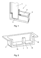
- FIG. 1 a conventional combined shower and / or bathing device with a lower entry area
- Fig. 2 shows a first embodiment of a trough for a combined shower and / or bathing device according to the invention in a perspective view
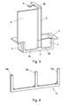
- Fig. 3 1 is a perspective view of a first embodiment of a shower and / or bathing device according to the invention
- Fig. 4 shows a stiffening structure for the trough of the device according to the invention
- Fig. 5 is a perspective view from below of a tub with another embodiment of a stiffening structure
- Fig. 6a and 6b show an embodiment of a shower and / or bathing device according to the invention with sliding door
- Fig. 7 shows a further embodiment of the invention for a tub for a combined shower and / or bathing device according to the invention.
- An in FIG. 1 illustrated bathing and shower device 1 consists of a trough 2 with a lowered, approximately at ground level arranged entry area 3, which can be sealed watertight by an optionally over the edge 5 of the tub 2 in the height projecting door 4. It has a bathing area, possibly with an integrated seat surface, and a shower area and can be produced in any desired manner, for example as a coated, for example enamelled deep-drawn part of a metallic material or as a molded or deep-drawn acrylic tub, or as a GRP, CFK or another fiber-reinforced plastic by hand lay-up or spraying method.
- the door 4 will advantageously be made of a clear, transparent material, such as mineral or plexiglass or acrylic glass, with an inwardly opening door 4 for small bathrooms is advantageous. Door 4 is filled with tub 2 under the water pressure, which contributes to the tightness.
- the in Fig. 2 Shaped shape has been developed.
- one of the side walls 2a of the trough 2 is provided with a recess 2b extending substantially over the entire length and depth of the side wall 2a.
- Such a, over a substantially entire side open component 2 is easier and more economical to make than a tub with entry and exit areas of lesser dimensions in an otherwise closed side wall.
- two such molded parts can be manufactured together with little material waste, preferably in the deep drawing process.
- a door 4 is provided, which substantially the Half of this recess 2b covers, while the other half of the recess 2b by another, separate component 6, which is preferably made of a material other than the tub 2, preferably as the door 4 made of a clear, transparent material, is watertight , Nevertheless, according to the invention, the expenditure and pivoting range for the door 4 designed as a pivot door in this illustrated embodiment can be kept low, as it still has to cover only part of the side wall of the tub 2.
- the effort and space required for the complete sealing and sealing can be kept low, but for the user high comfort - through the almost ground level possible entry, especially when used as a shower - and the high flexibility in use - Is given either as a shower or possibly with the door closed 4 as a bathtub -.
- the fix mounted component 6 may - as in Fig. 3 shown - extend to form a shower enclosure over the height of the tub rim 5 addition to advantageously up to the ceiling of the bathroom.
- An extension along the entire, not covered by the door 4 length of the tub 2 in the horizontal direction and optionally also a preferably complete coverage of the adjoining end wall is possible.
- a bulge 7 is provided in the central region of the recess 2b, in the region of the transition between the door 4 and that of the separate component 6, a bulge 7 is provided.
- This bulge 7 may extend to a height of substantially height of the remaining walls of the tub 2.
- the bulge 7 but extends only slightly beyond the level of the lower edge of the entry into the tub 2 and the lower edge of the recess 2b and is extended upwards by a center column 8.
- This center column 8 can - as in the case of Fig. 2 - In the amount of the edge 5 of the trough 2, that is, in a height of substantially the height of the remaining walls of the trough 2, end or else be extended beyond, as exemplified in Fig. 3 shown.
- the center column 8 or a bulge 7 with extension up to the tub rim 5 separates the area of the door 4 and the area of the permanently mounted separate component 6.
- a center pillar 8 extending beyond the tub rim 5 may be provided with transverse structures 8a which extend above the tub 2 towards the interior thereof and may carry, for example, at least one shower head 9, which may preferably be connected to the water supply through the center pillar 8.
- at least one water guide can be integrated therein, for example a likewise provided in the center column and thus in the vicinity of the still standing outside the tub 2 user pan inlet, a tub overflow or a combination of these two valves.
- a stiffening structure 10 for stiffening and stabilizing the component 2 in the lower and middle region of the recess 2b, a stiffening structure 10 (see Fig. 4 ) for at least the region of the vertical portions of the recess, ie the area from the bottom edge up to the height of the edge 5 of the side walls of the tub 2, be provided.
- the two side parts 10a extend at the edges of the recess 2b up to the tub rim 5.
- a stiffening is also provided for the area of the bulge 7 or a further up to at least the level of the edge 5 of the tub rising center column 8, for which a middle part 10b at least extend into the bulge 7 or center column 8 and preferably also can extend to at least the height of the tub rim 5.
- the bulge 7 has to be provided with an opening for the passage of this middle part 10b of the stiffening structure 10, wherein this middle part 10b can also be used as an assembly option for a center column 8.
- the stiffening structure 10 of Fig. 4 can - as in Fig. 5 can be seen - be advantageously connected to a floor construction 10c and can extend below the tub 2 to the opposite side and support there.
- a deformation of the tub 2 and resulting leaks in the area of the door 4, the component 6 or the transition from the bulge 7 to the attached center pillar 8 be avoided.
- the water pressure in this design supports the sealing effect with the door closed.
- the center column 8 may additionally have longitudinal structures 8b for this embodiment in particular, which may carry, for example, guides for the door 4 designed as a sliding door.
- the longitudinal structures 8b can of course also be achieved with only the height of the tub rim 5
- Center column 8 may be provided, in which case a possible sliding door 4 would only reach to the edge.
- FIG. 7 Compared to conventional tubs, an advantageous embodiment according to the present invention, which in Fig. 7 is shown, further for at least one end wall or at least the recess 2b opposite side wall on a substantially horizontal and compared to the conventional dimensions widened tub rim 5a, wherein any adjoining and substantially vertical panel is avoided.
- a volume defined by the component 2 and the widened tub rim 5a is created in the area between the at least one wall and the adjacent component 2, in which ducts or the like above plaster and nevertheless invisible to the user.
- tub 2 advantageously in the region of the door 4 and / or the separate component 6 formations to the waterproof connection, preferably using an inner, circumferential seal 11, which also in Fig. 7 illustrated, of course, but is also provided in all other embodiments of the invention.
Abstract
Description
Die Erfindung betrifft eine Bade- und/oder Duschvorrichtung, umfassend eine Wanne mit einem abgesenkten und durch eine bewegliche Tür wasserdicht verschließbaren Einstiegsbereich.The invention relates to a bath and / or shower device comprising a tub with a lowered and by a movable door watertight closable entry area.
Bade- und/oder Duschvorrichtungen mit einer einen niederen, ebenerdigen oder fast ebenerdigen Rand aufweisenden Duschwanne ermöglichen es nicht, in der Duschwanne sitzend ein vollwertiges Bad zu nehmen. Demgegenüber ermöglicht eine herkömmliche Badewanne, allenfalls mit einem Spritzschutz in Form eines Duschvorhangs oder einem aus Glasscheiben bestehenden Duschaufsatz, zwar das Duschen und Baden, wohingegen ein ebenerdiger oder fast ebenerdiger Einstieg wie in eine Duschwanne hinein nicht möglich ist, da der hohe Rand der Badewanne überklettert werden muss, was insbesondere für Gehbehinderte und ältere Menschen ein fast unüberwindbares Hindernis darstellt. Daher wird oftmals mit erheblichem Platzbedarf und erhöhten Kosten sowohl eine Dusche als auch eine Badewanne installiert.Bathing and / or shower facilities with a lower, ground-level or almost ground-level edge shower tray do not allow to sit in the shower tray to take a full bath. In contrast, allows a conventional bathtub, possibly with a splash guard in the form of a shower curtain or glass shower screen, while showering and bathing, whereas a ground-level or almost ground-level entrance as in a shower tray is not possible because of the high edge of the bathtub climbs which is an almost insurmountable obstacle, especially for disabled and elderly people. Therefore, often with considerable space requirements and increased costs, both a shower and a bathtub installed.
Als Weiterentwicklung kombinierter Bade- und/oder Duschvorrichtungen wurden dann Systeme wie beispielsweise in der
Derartige Wannen bzw. Unterbauten für Bade- und/oder Duschvorrichtungen sind relativ kompliziert geformte Bauteile mit sehr aufwendiger Fertigung, insbesondere bei Berücksichtigung der für die Dichtheit notwendigen Stabilität und Aufnahme aller Kräfte.Such tubs or substructures for bathing and / or shower facilities are relatively complicated shaped components with very complex manufacturing, especially taking into account the necessary for the tightness stability and absorption of all forces.
Die Aufgabe der vorliegenden Erfindung war daher eine Vorrichtung, welche bei ausreichender Stabilität eine einfache und materialsparende Fertigung zulässt.The object of the present invention was therefore a device which permits a simple and material-saving production with sufficient stability.
Zur Lösung dieser Aufgabe ist eine eingangs beschriebene Vorrichtung erfindungsgemäß dadurch gekennzeichnet, dass eine der Seitenwände der Wanne mit einer sich im Wesentlichen über die gesamte Länge und Tiefe der Seitenwand erstreckenden Ausnehmung versehen ist, dass die bewegliche Tür im Wesentlichen die Hälfte dieser Ausnehmung abdeckt und die andere Hälfte der Ausnehmung durch einen weiteren, separaten und fix montierten Bauteil wasserdicht verschlossen ist. Ein über eine im Wesentlichen gesamte Seite offener Bauteil ist einfacher anzufertigen als Wanne mit Ein- und Ausstiegsbereichen geringerer Dimensionen, wobei aber durch den fix montierten Bauteil der Aufwand und Platzbedarf für die den anderen Teil der offenen Seite abdeckenden Tür gering gehalten ist. Damit können hoher Komfort für den Benutzer und hohe Flexibilität in der Nutzung - entweder als Dusche oder gegebenenfalls als Badewanne - mit einer relativ einfachen und wirtschaftlichen Fertigung in Einklang gebracht werden.To achieve this object, a device described above is inventively characterized in that one of the side walls of the tub is provided with a substantially over the entire length and depth of the side wall extending recess, that the movable door covers substantially half of this recess and the another half of the recess is sealed watertight by another, separate and permanently mounted component. An over a substantially entire side open component is easier to make than tub with entry and exit areas lesser dimensions, but is kept low by the fixed component of the effort and space required for the other part of the open side door covering. Thus, high comfort for the user and high flexibility in use - either as a shower or possibly as a bathtub - can be reconciled with a relatively simple and economical production.
Gemäß einer vorteilhaften Ausführungsform der Erfindung ist die Vorrichtung dadurch gekennzeichnet, dass im mittleren Bereich der Ausnehmung, zwischen dem Bereich der Tür und jener des separaten Bauteils, eine Aufwölbung mit einer Höhe bis im Wesentlichen zur Höhe der übrigen Wände der Wanne und/oder eine Mittelsäule vorgesehen ist, wobei vorzugsweise zumindest eine Wasserführung in der Mittelsäule integriert ist. Damit ist die Stabilität im Bereich der offenen Seite erhöht und kann durch zusätzliche Einbauten im Bereich der Aufwölbung bzw. einer gegebenenfalls separat montierten Mittelsäule, die den Bereich der Tür und den Bereich des fix montierten separaten Bauteils trennt, bei Bedarf noch weiter erhöht werden. Die Mittelsäule kann zusätzlich zumindest eine Wasserführung aufweisen, etwa zur Versorgung eines ebenfalls in der Mittelsäule integrierten Wannenzulaufs, eines Überlaufes oder auch eines Duschkopfes, was vorzugsweise bei einer über die Wannenrandhöhe hinausgehenden Mittelsäule der Fall sein wird.According to an advantageous embodiment of the invention, the device is characterized in that in the central region of the recess, between the region of the door and that of the separate component, a bulge having a height substantially to the height of the remaining walls of the tub and / or a center column is provided, wherein preferably at least one water guide is integrated in the center column. Thus, the stability is increased in the area of the open side and can be further increased if necessary by additional installations in the region of the bulge or an optionally separately mounted center column, which separates the area of the door and the area of the permanently mounted separate component. The center column may additionally comprise at least one water guide, for example for supplying a well inlet integrated in the center column, an overflow or even a shower head, which will preferably be the case with a center pillar extending beyond the tub edge height.
Dies kann beispielsweise dadurch geschehen, dass eine Versteifungsstruktur für zumindest den Bereich der vertikalen Abschnitte der Ausnehmung, vorzugsweise auch den Bereich der Aufwölbung bzw. der Mittelsäule, vorgesehen ist, allenfalls mit einer Anbindung an eine Bodenkonstruktion. Über eine derartige Versteifungsstruktur können die vom Wasser und auch durch die Benutzung der Wanne - etwa wenn sich der Benutzer an der Wanne abstützt - aufgenommen und gegebenenfalls durch eine Verbindung der Versteifungsstruktur mit Boden oder Wand eine Undichtheiten verursachende Verformung der Wanne vermieden werden.This can be done, for example, by providing a stiffening structure for at least the region of the vertical sections of the recess, preferably also the region of the bulge or of the center column, possibly with a connection to a floor construction. About such a stiffening structure of the water and also by the use of the tub - such as when the user is supported on the tub - recorded and optionally avoided by a connection of the stiffening structure with the bottom or wall a leakage causing deformation of the tub.
Eine einfache, geringen Platzbedarf und Gewicht aufweisende Konstruktion ist durch eine Ausführungsform gegeben, bei welcher eine gabelförmige Versteifungsstruktur den Bereich der Ausnehmung allseitig umgibt, wobei zwei Seitenteile dieser Struktur sich an den Rändern der Ausnehmung bis hinauf zum Wannenrand erstrecken und ein mittlerer Teil in die Aufwölbung bzw. Mittelsäule zumindest hineinragt, vorzugsweise sich ebenfalls bis zumindest zur Höhe des Wannenrandes erstreckt, wobei allenfalls die Aufwölbung mit einer Öffnung zur Durchführung dieses mittleren Teils versehen ist.A simple, low footprint and weight construction is given by an embodiment in which a fork-shaped stiffening structure surrounds the area of the recess on all sides, with two side parts of this structure extending at the edges of the recess up to the tub rim and a central part in the Buckle or center column protrudes at least, preferably also extends at least to the height of the tub rim, at best, the bulge is provided with an opening for the implementation of this central part.
Für den komfortablen Einstieg in die Bade- und/oder Duschvorrichtung und bei Verwendung als Badewanne gleichzeitig sichere Abdichtung ist es besonders vorteilhaft, wenn die Tür als Schwenktür, welche an der Innenseite der Wanne anschlägt und nach innen zu öffnen ist, oder als vorzugsweise in Richtung des separaten Bauteils zu öffnende Schiebetür ausgeführt ist, welche zumindest bis zur Höhe des Wannenrandes reicht. In beiden Fällen unterstützt der Wasserdruck die Dichtwirkung bei geschlossener Tür, so dass aufwendige Mittel zum Anpressen oder Heranziehen der Tür vermieden werden können.For comfortable entry into the bath and / or shower device and when used as a bathtub at the same time secure seal, it is particularly advantageous if the door as a hinged door, which strikes against the inside of the tub and to open inward, or preferably in the direction of the separate component to be opened sliding door is executed, which extends at least up to the height of the tub rim. In both cases, the water pressure supports the sealing effect when the door is closed, so that expensive means for pressing or pulling the door can be avoided.
Eine weitere Erhöhung des Komforts ist durch eine Ausführungsform gegeben, bei welcher der separate Bauteil als sich in der Höhe über den Wannenrand hinaus, allenfalls auch horizontal bis in den Bereich der anschließenden Stirnwand, erstreckende Duschabtrennung ausgeführt ist.A further increase of the comfort is given by an embodiment in which the separate component is designed as extending in height above the tub rim, possibly also horizontally up to the area of the adjoining end wall, extending shower enclosure.
Mit einer Herstellung der Tür und/oder des separaten Bauteils aus einem klaren, transparenten Werkstoff kann eine weitere Erhöhung des Komforts erzielt werden.With a production of the door and / or the separate component made of a clear, transparent material, a further increase in comfort can be achieved.
Gemäß einer weiteren vorteilhaften Ausführungsform der Erfindung ist die Vorrichtung dadurch gekennzeichnet, dass bei zumindest einer Stirn- oder Seitenwand der Wanne, vorzugsweise zumindest der der Ausnehmung gegenüberliegenden Seitenwand, ein im Wesentlichen horizontaler, breiter Wannenrand ohne anschließender vertikaler Verkleidung vorgesehen ist. Durch eine derartige Formgebung wird im Bereich zwischen der Wand oder den Wänden und dem daran anliegenden Bauteil ein verstecktes Volumen geschaffen, das die Unterbringung von Leitungen über Putz und daher ohne Bearbeitung des umgebenden Mauerwerks, aber dennoch vor den Blicken des Benutzers verborgen, und auch die Montage oder Durchführung von Armaturen, gestattet. Weiters kann durch eine solche Formgebung ausreichend Platz im oberen Körperbereich für komfortables Duschen ohne allzu große Einschränkung der Bewegungsfreiheit mit einem kleinen, für Vollbäder notwendigen Wasservolumen verbunden werden. Daneben bietet ein breiter Wannenrand eine gute Sitzgelegenheit für den Benutzer und Raum für die Unterbringung von Stauraum für Badeutensilien.According to a further advantageous embodiment of the invention, the device is characterized in that at least one end or side wall of the trough, preferably at least the side wall opposite the recess, a substantially horizontal, wide tub rim is provided without subsequent vertical panel. Such a shaping creates a hidden volume in the area between the wall or the walls and the adjacent component, which conceals the placement of pipes over plaster and therefore without processing the surrounding masonry, but still in front of the eyes of the user, and also Assembly or implementation of fittings allowed. Furthermore, such a design allows sufficient space in the upper body area for comfortable showering without too much restriction of freedom of movement with a small volume of water necessary for full baths. In addition, a wide tub edge provides good seating for the user and space for storing storage space for bathing utensils.
Wenn gemäß einer weiteren Ausführungsform der Erfindung die Wanne als Form-oder Tiefziehteil, vorzugsweise aus Kunststoffmaterial, ausgebildet ist, gestattet dies eine einfache und materialsparende Fertigung. So können bei geringem Materialabfall jeweils zwei derartige Formteile gemeinsam gefertigt werden, vorzugsweise im Tiefziehverfahren.If according to a further embodiment of the invention, the trough is designed as a molded or deep-drawn part, preferably made of plastic material, this allows a simple and material-saving production. Thus, two such molded parts can be manufactured together with little material waste, preferably in the deep drawing process.
Um eine gute Dichtheit zu gewährleisten, weist die Wanne im Bereich der Tür und/oder des separaten Bauteils Ausformungen zu deren wasserdichten Anbindung auf, vorzugsweise unter Verwendung einer innenliegenden, umlaufenden Dichtung.In order to ensure a good tightness, the trough has in the region of the door and / or the separate component formations for their watertight connection, preferably using an internal peripheral seal.
Ein nicht einschränkendes Ausführungsbeispiel der Erfindung ist in den Zeichnungen schematisch dargestellt und wird im Folgenden näher erläutert.A non-limiting embodiment of the invention is shown schematically in the drawings and will be explained in more detail below.
Dabei zeigt die
Eine in
Um nun eine trotz ausreichender Stabilität einfachere und materialsparende Fertigung einer kombinierten Bade- und/oder Duschvorrichtung zu ermöglichen, ist die in
Bei der gebrauchsfertigen Dusch- und/oder Badevorrichtung, wie in
Der fix montierte Bauteil 6 kann sich - wie in
Wie weiters in
Eine sich über den Wannenrand 5 hinausgehende Mittelsäule 8 kann mit Querstrukturen 8a versehen sein, die sich oberhalb der Wanne 2 zu deren Innerem hin erstrecken und beispielsweise zumindest einen Duschkopf 9 tragen können, der vorzugsweise durch die Mittelsäule 8 hindurch an die Wasserversorgung angeschlossen sein kann. Selbst bei niedrigerer Mittelsäule 8 kann zumindest eine Wasserführung darin integriert sein, die beispielsweise einen ebenfalls in der Mittelsäule und damit im Nahbereich des noch außerhalb der Wanne 2 stehenden Benutzers vorgesehenen Wannenzulauf, einen Wannenüberlauf oder eine Kombination dieser beiden Armaturen.A
Zur Versteifung und Stabilisierung des Bauteils 2 im unteren und mittleren Bereich der Ausnehmung 2b kann eine Versteifungsstruktur 10 (siehe
Die Versteifungsstruktur 10 der
Alternativ zu der bereits oben erwähnten Ausführung der Tür 4 als Schwenktür ist ein komfortabler Einstieg in die erfindungsgemäße Bade- und/oder Duschvorrichtung und bei Verwendung als Badewanne gleichzeitig eine sichere Abdichtung gewährleistet, wenn die Tür 4 als Schiebetür ausgeführt ist (siehe
Gegenüber herkömmlichen Wannen weist eine vorteilhafte Ausführungsform gemäß der vorliegenden Erfindung, welche in
Um eine gute Dichtheit zu gewährleisten, weist die Wanne 2 vorteilhafterweise im Bereich der Tür 4 und/oder des separaten Bauteils 6 Ausformungen zu deren wasserdichten Anbindung auf, vorzugsweise unter Verwendung einer innenliegenden, umlaufenden Dichtung 11, die ebenfalls in
Claims (10)
Applications Claiming Priority (1)
| Application Number | Priority Date | Filing Date | Title |
|---|---|---|---|
| ATA159/2011A AT511016B1 (en) | 2011-02-07 | 2011-02-07 | BATH AND / OR SHOWER |
Publications (3)
| Publication Number | Publication Date |
|---|---|
| EP2484257A2 true EP2484257A2 (en) | 2012-08-08 |
| EP2484257A3 EP2484257A3 (en) | 2014-10-08 |
| EP2484257B1 EP2484257B1 (en) | 2016-07-27 |
Family
ID=45464438
Family Applications (1)
| Application Number | Title | Priority Date | Filing Date |
|---|---|---|---|
| EP12150945.9A Not-in-force EP2484257B1 (en) | 2011-02-07 | 2012-01-12 | Bath and/or shower device |
Country Status (5)
| Country | Link |
|---|---|
| US (1) | US20120198611A1 (en) |
| EP (1) | EP2484257B1 (en) |
| CN (1) | CN102626296A (en) |
| AT (1) | AT511016B1 (en) |
| CA (1) | CA2766567A1 (en) |
Families Citing this family (6)
| Publication number | Priority date | Publication date | Assignee | Title |
|---|---|---|---|---|
| EP2395882B1 (en) | 2009-02-13 | 2013-07-03 | Koninklijke Philips Electronics N.V. | Floor construction with variable grade of resilience |
| US10314440B2 (en) | 2016-05-31 | 2019-06-11 | Les Produits Neptune Inc. | Bathtub with door and drain |
| USD842972S1 (en) | 2017-01-12 | 2019-03-12 | Kohler Co. | Walk in bath |
| US10881251B2 (en) | 2017-01-12 | 2021-01-05 | Kohler Co. | Walk in bath |
| USD895078S1 (en) * | 2017-05-24 | 2020-09-01 | Duravit Aktiengesellschaft | Shower with bath |
| ES1290457Y (en) * | 2022-04-01 | 2022-08-03 | Perez Diego Moreno | BATHROOM STRUCTURE |
Citations (5)
| Publication number | Priority date | Publication date | Assignee | Title |
|---|---|---|---|---|
| US5351345A (en) | 1992-07-08 | 1994-10-04 | Siltech Products Incorporated | Bath tub having side access |
| DE29914087U1 (en) | 1999-08-12 | 2001-01-04 | Brachmann Reinhold | Bath shower |
| US6226808B1 (en) | 2000-06-16 | 2001-05-08 | Donal Walshe | Bathtub and shower combination |
| CN101342060A (en) | 2007-07-12 | 2009-01-14 | 陈亦然 | Door open type bathtub |
| USD622363S1 (en) | 2009-02-25 | 2010-08-24 | Artweger Gmbh & Co. | Walk-in bathtub |
Family Cites Families (14)
| Publication number | Priority date | Publication date | Assignee | Title |
|---|---|---|---|---|
| US2068457A (en) * | 1936-09-04 | 1937-01-19 | Raymond S Kirkwood | Bathtub |
| US3052930A (en) * | 1959-11-17 | 1962-09-11 | Pan American Window Corp | Sliding door construction |
| US3864762A (en) * | 1972-03-01 | 1975-02-11 | Eve B Finch | Elevated safety bathtub |
| US4198715A (en) * | 1978-10-30 | 1980-04-22 | Novi Plastics Company | Shower cabinet and base |
| US4360935A (en) * | 1981-09-08 | 1982-11-30 | Barrett Sr John P | Deep bathtub with elevated seat and entrance door |
| US5108088A (en) * | 1987-02-12 | 1992-04-28 | Stewart Medical, Inc. | Exercise device with underwater treadmill |
| US5001787A (en) * | 1989-12-04 | 1991-03-26 | Kimstock, Inc. | Combination bathtub/shower facility |
| JPH07305523A (en) * | 1994-05-11 | 1995-11-21 | Sekisui Chem Co Ltd | Bath room equipment |
| JPH08209958A (en) * | 1995-02-06 | 1996-08-13 | Sekisui Chem Co Ltd | Housing equipment or bathroom equipment |
| US5778463A (en) * | 1996-10-01 | 1998-07-14 | Universal Rundle Corporation | Multi-piece tub/shower unit and method of installation |
| USD427294S (en) * | 1999-01-22 | 2000-06-27 | Hansgrohe Ag | Shower fixture |
| JP2002017888A (en) * | 2000-07-05 | 2002-01-22 | Sakai Medical Co Ltd | Bathtub for walking training |
| CA107405S (en) * | 2004-06-28 | 2005-12-06 | Maax Canada Inc | Shower |
| GB2438468A (en) * | 2006-05-26 | 2007-11-28 | Aqualux Products Ltd | Shower screen arrangement |
-
2011
- 2011-02-07 AT ATA159/2011A patent/AT511016B1/en not_active IP Right Cessation
-
2012
- 2012-01-12 EP EP12150945.9A patent/EP2484257B1/en not_active Not-in-force
- 2012-02-01 US US13/363,986 patent/US20120198611A1/en not_active Abandoned
- 2012-02-06 CN CN2012100247185A patent/CN102626296A/en active Pending
- 2012-02-06 CA CA2766567A patent/CA2766567A1/en not_active Abandoned
Patent Citations (5)
| Publication number | Priority date | Publication date | Assignee | Title |
|---|---|---|---|---|
| US5351345A (en) | 1992-07-08 | 1994-10-04 | Siltech Products Incorporated | Bath tub having side access |
| DE29914087U1 (en) | 1999-08-12 | 2001-01-04 | Brachmann Reinhold | Bath shower |
| US6226808B1 (en) | 2000-06-16 | 2001-05-08 | Donal Walshe | Bathtub and shower combination |
| CN101342060A (en) | 2007-07-12 | 2009-01-14 | 陈亦然 | Door open type bathtub |
| USD622363S1 (en) | 2009-02-25 | 2010-08-24 | Artweger Gmbh & Co. | Walk-in bathtub |
Also Published As
| Publication number | Publication date |
|---|---|
| AT511016B1 (en) | 2014-03-15 |
| CN102626296A (en) | 2012-08-08 |
| EP2484257A3 (en) | 2014-10-08 |
| CA2766567A1 (en) | 2012-08-07 |
| US20120198611A1 (en) | 2012-08-09 |
| EP2484257B1 (en) | 2016-07-27 |
| AT511016A1 (en) | 2012-08-15 |
Similar Documents
| Publication | Publication Date | Title |
|---|---|---|
| EP2484257B1 (en) | Bath and/or shower device | |
| DE202011051140U1 (en) | Cover box for a shower drain system | |
| EP1611827B1 (en) | Combined bathing and showering device | |
| DE1554593B1 (en) | Shower cubicle | |
| DE102005021702A1 (en) | Bathroom for camping mobile, has shower tub that is removably supported under toilet, door supported on another door and vertical roller attached to free end edges of former door and at door frame of latter door | |
| DE4420711A1 (en) | Shower partition | |
| EP2581507A1 (en) | Shower and profile element for same | |
| DE8507269U1 (en) | Device for supporting and covering sanitary basins, in particular bathtubs and shower trays | |
| DE19503514C2 (en) | bathtub | |
| DE102006000877A1 (en) | Bathing or showering device has bolting device provided with first sensor that determines condition of bolting device and controllable sealing device is added to siphon | |
| EP0953309B1 (en) | Shower booth | |
| DE202016105011U1 (en) | Wall installation unit | |
| DE10114195B4 (en) | Sanitary shower facility | |
| DE19702214A1 (en) | shower | |
| DE202011100530U1 (en) | bathtub | |
| DE19829884B4 (en) | Splash protection for bathtubs | |
| DE102004016447B4 (en) | Cabin for showering and / or steam bathing with side jets | |
| WO2004046471A1 (en) | Shower assembly | |
| DE102021132768A1 (en) | Recreational vehicle with a room divider for a sanitary cell | |
| DE202005007468U1 (en) | Vehicle e.g. camper, bath, has shower tub placed under toilet in displaceable manner, and door swiveled towards another door, where curtain is attached on free edge of one door and at frame of another door | |
| DE102019126139A1 (en) | Combination tub for showering and bathing | |
| DE102009004396A1 (en) | Device for personal hygiene, comprises shower area with shower device and bathing device, where bathing device comprises bathtub which is placed in usage position by position changing device by pivot point | |
| DE8005995U1 (en) | FOLDING SHOWER AND / OR BATHROOM | |
| EP2241233A2 (en) | Shower device | |
| DE102008037290A1 (en) | Bath device for use as e.g. bath tub, by handicapped person, has tub body surrounded by shower enclosure and designed as foil such that showering tub or bath tub is formed within same tub body |
Legal Events
| Date | Code | Title | Description |
|---|---|---|---|
| PUAI | Public reference made under article 153(3) epc to a published international application that has entered the european phase |
Free format text: ORIGINAL CODE: 0009012 |
|
| AK | Designated contracting states |
Kind code of ref document: A2 Designated state(s): AL AT BE BG CH CY CZ DE DK EE ES FI FR GB GR HR HU IE IS IT LI LT LU LV MC MK MT NL NO PL PT RO RS SE SI SK SM TR |
|
| AX | Request for extension of the european patent |
Extension state: BA ME |
|
| PUAL | Search report despatched |
Free format text: ORIGINAL CODE: 0009013 |
|
| AK | Designated contracting states |
Kind code of ref document: A3 Designated state(s): AL AT BE BG CH CY CZ DE DK EE ES FI FR GB GR HR HU IE IS IT LI LT LU LV MC MK MT NL NO PL PT RO RS SE SI SK SM TR |
|
| AX | Request for extension of the european patent |
Extension state: BA ME |
|
| RIC1 | Information provided on ipc code assigned before grant |
Ipc: A47K 3/20 20060101AFI20140829BHEP |
|
| 17P | Request for examination filed |
Effective date: 20150203 |
|
| RBV | Designated contracting states (corrected) |
Designated state(s): AL AT BE BG CH CY CZ DE DK EE ES FI FR GB GR HR HU IE IS IT LI LT LU LV MC MK MT NL NO PL PT RO RS SE SI SK SM TR |
|
| GRAP | Despatch of communication of intention to grant a patent |
Free format text: ORIGINAL CODE: EPIDOSNIGR1 |
|
| INTG | Intention to grant announced |
Effective date: 20160203 |
|
| GRAS | Grant fee paid |
Free format text: ORIGINAL CODE: EPIDOSNIGR3 |
|
| GRAA | (expected) grant |
Free format text: ORIGINAL CODE: 0009210 |
|
| AK | Designated contracting states |
Kind code of ref document: B1 Designated state(s): AL AT BE BG CH CY CZ DE DK EE ES FI FR GB GR HR HU IE IS IT LI LT LU LV MC MK MT NL NO PL PT RO RS SE SI SK SM TR |
|
| REG | Reference to a national code |
Ref country code: GB Ref legal event code: FG4D Free format text: NOT ENGLISH |
|
| REG | Reference to a national code |
Ref country code: CH Ref legal event code: EP |
|
| REG | Reference to a national code |
Ref country code: AT Ref legal event code: REF Ref document number: 815087 Country of ref document: AT Kind code of ref document: T Effective date: 20160815 |
|
| REG | Reference to a national code |
Ref country code: IE Ref legal event code: FG4D Free format text: LANGUAGE OF EP DOCUMENT: GERMAN |
|
| REG | Reference to a national code |
Ref country code: DE Ref legal event code: R096 Ref document number: 502012007752 Country of ref document: DE |
|
| REG | Reference to a national code |
Ref country code: CH Ref legal event code: NV Representative=s name: ISLER AND PEDRAZZINI AG, CH |
|
| REG | Reference to a national code |
Ref country code: LT Ref legal event code: MG4D |
|
| REG | Reference to a national code |
Ref country code: NL Ref legal event code: MP Effective date: 20160727 |
|
| PG25 | Lapsed in a contracting state [announced via postgrant information from national office to epo] |
Ref country code: RS Free format text: LAPSE BECAUSE OF FAILURE TO SUBMIT A TRANSLATION OF THE DESCRIPTION OR TO PAY THE FEE WITHIN THE PRESCRIBED TIME-LIMIT Effective date: 20160727 Ref country code: LT Free format text: LAPSE BECAUSE OF FAILURE TO SUBMIT A TRANSLATION OF THE DESCRIPTION OR TO PAY THE FEE WITHIN THE PRESCRIBED TIME-LIMIT Effective date: 20160727 Ref country code: IT Free format text: LAPSE BECAUSE OF FAILURE TO SUBMIT A TRANSLATION OF THE DESCRIPTION OR TO PAY THE FEE WITHIN THE PRESCRIBED TIME-LIMIT Effective date: 20160727 Ref country code: FI Free format text: LAPSE BECAUSE OF FAILURE TO SUBMIT A TRANSLATION OF THE DESCRIPTION OR TO PAY THE FEE WITHIN THE PRESCRIBED TIME-LIMIT Effective date: 20160727 Ref country code: NL Free format text: LAPSE BECAUSE OF FAILURE TO SUBMIT A TRANSLATION OF THE DESCRIPTION OR TO PAY THE FEE WITHIN THE PRESCRIBED TIME-LIMIT Effective date: 20160727 Ref country code: HR Free format text: LAPSE BECAUSE OF FAILURE TO SUBMIT A TRANSLATION OF THE DESCRIPTION OR TO PAY THE FEE WITHIN THE PRESCRIBED TIME-LIMIT Effective date: 20160727 Ref country code: IS Free format text: LAPSE BECAUSE OF FAILURE TO SUBMIT A TRANSLATION OF THE DESCRIPTION OR TO PAY THE FEE WITHIN THE PRESCRIBED TIME-LIMIT Effective date: 20161127 Ref country code: NO Free format text: LAPSE BECAUSE OF FAILURE TO SUBMIT A TRANSLATION OF THE DESCRIPTION OR TO PAY THE FEE WITHIN THE PRESCRIBED TIME-LIMIT Effective date: 20161027 |
|
| PG25 | Lapsed in a contracting state [announced via postgrant information from national office to epo] |
Ref country code: PT Free format text: LAPSE BECAUSE OF FAILURE TO SUBMIT A TRANSLATION OF THE DESCRIPTION OR TO PAY THE FEE WITHIN THE PRESCRIBED TIME-LIMIT Effective date: 20161128 Ref country code: PL Free format text: LAPSE BECAUSE OF FAILURE TO SUBMIT A TRANSLATION OF THE DESCRIPTION OR TO PAY THE FEE WITHIN THE PRESCRIBED TIME-LIMIT Effective date: 20160727 Ref country code: SE Free format text: LAPSE BECAUSE OF FAILURE TO SUBMIT A TRANSLATION OF THE DESCRIPTION OR TO PAY THE FEE WITHIN THE PRESCRIBED TIME-LIMIT Effective date: 20160727 Ref country code: GR Free format text: LAPSE BECAUSE OF FAILURE TO SUBMIT A TRANSLATION OF THE DESCRIPTION OR TO PAY THE FEE WITHIN THE PRESCRIBED TIME-LIMIT Effective date: 20161028 Ref country code: LV Free format text: LAPSE BECAUSE OF FAILURE TO SUBMIT A TRANSLATION OF THE DESCRIPTION OR TO PAY THE FEE WITHIN THE PRESCRIBED TIME-LIMIT Effective date: 20160727 Ref country code: ES Free format text: LAPSE BECAUSE OF FAILURE TO SUBMIT A TRANSLATION OF THE DESCRIPTION OR TO PAY THE FEE WITHIN THE PRESCRIBED TIME-LIMIT Effective date: 20160727 |
|
| PG25 | Lapsed in a contracting state [announced via postgrant information from national office to epo] |
Ref country code: RO Free format text: LAPSE BECAUSE OF FAILURE TO SUBMIT A TRANSLATION OF THE DESCRIPTION OR TO PAY THE FEE WITHIN THE PRESCRIBED TIME-LIMIT Effective date: 20160727 Ref country code: EE Free format text: LAPSE BECAUSE OF FAILURE TO SUBMIT A TRANSLATION OF THE DESCRIPTION OR TO PAY THE FEE WITHIN THE PRESCRIBED TIME-LIMIT Effective date: 20160727 |
|
| REG | Reference to a national code |
Ref country code: DE Ref legal event code: R097 Ref document number: 502012007752 Country of ref document: DE |
|
| PG25 | Lapsed in a contracting state [announced via postgrant information from national office to epo] |
Ref country code: SM Free format text: LAPSE BECAUSE OF FAILURE TO SUBMIT A TRANSLATION OF THE DESCRIPTION OR TO PAY THE FEE WITHIN THE PRESCRIBED TIME-LIMIT Effective date: 20160727 Ref country code: SK Free format text: LAPSE BECAUSE OF FAILURE TO SUBMIT A TRANSLATION OF THE DESCRIPTION OR TO PAY THE FEE WITHIN THE PRESCRIBED TIME-LIMIT Effective date: 20160727 Ref country code: BG Free format text: LAPSE BECAUSE OF FAILURE TO SUBMIT A TRANSLATION OF THE DESCRIPTION OR TO PAY THE FEE WITHIN THE PRESCRIBED TIME-LIMIT Effective date: 20161027 Ref country code: DK Free format text: LAPSE BECAUSE OF FAILURE TO SUBMIT A TRANSLATION OF THE DESCRIPTION OR TO PAY THE FEE WITHIN THE PRESCRIBED TIME-LIMIT Effective date: 20160727 Ref country code: BE Free format text: LAPSE BECAUSE OF NON-PAYMENT OF DUE FEES Effective date: 20170131 Ref country code: CZ Free format text: LAPSE BECAUSE OF FAILURE TO SUBMIT A TRANSLATION OF THE DESCRIPTION OR TO PAY THE FEE WITHIN THE PRESCRIBED TIME-LIMIT Effective date: 20160727 |
|
| PLBE | No opposition filed within time limit |
Free format text: ORIGINAL CODE: 0009261 |
|
| STAA | Information on the status of an ep patent application or granted ep patent |
Free format text: STATUS: NO OPPOSITION FILED WITHIN TIME LIMIT |
|
| 26N | No opposition filed |
Effective date: 20170502 |
|
| PG25 | Lapsed in a contracting state [announced via postgrant information from national office to epo] |
Ref country code: SI Free format text: LAPSE BECAUSE OF FAILURE TO SUBMIT A TRANSLATION OF THE DESCRIPTION OR TO PAY THE FEE WITHIN THE PRESCRIBED TIME-LIMIT Effective date: 20160727 |
|
| GBPC | Gb: european patent ceased through non-payment of renewal fee |
Effective date: 20170112 |
|
| PG25 | Lapsed in a contracting state [announced via postgrant information from national office to epo] |
Ref country code: MC Free format text: LAPSE BECAUSE OF FAILURE TO SUBMIT A TRANSLATION OF THE DESCRIPTION OR TO PAY THE FEE WITHIN THE PRESCRIBED TIME-LIMIT Effective date: 20160727 |
|
| REG | Reference to a national code |
Ref country code: FR Ref legal event code: ST Effective date: 20170929 |
|
| PG25 | Lapsed in a contracting state [announced via postgrant information from national office to epo] |
Ref country code: FR Free format text: LAPSE BECAUSE OF NON-PAYMENT OF DUE FEES Effective date: 20170131 |
|
| REG | Reference to a national code |
Ref country code: IE Ref legal event code: MM4A |
|
| PG25 | Lapsed in a contracting state [announced via postgrant information from national office to epo] |
Ref country code: LU Free format text: LAPSE BECAUSE OF NON-PAYMENT OF DUE FEES Effective date: 20170112 Ref country code: GB Free format text: LAPSE BECAUSE OF NON-PAYMENT OF DUE FEES Effective date: 20170112 |
|
| REG | Reference to a national code |
Ref country code: BE Ref legal event code: MM Effective date: 20170131 |
|
| PG25 | Lapsed in a contracting state [announced via postgrant information from national office to epo] |
Ref country code: IE Free format text: LAPSE BECAUSE OF NON-PAYMENT OF DUE FEES Effective date: 20170112 |
|
| PG25 | Lapsed in a contracting state [announced via postgrant information from national office to epo] |
Ref country code: MT Free format text: LAPSE BECAUSE OF FAILURE TO SUBMIT A TRANSLATION OF THE DESCRIPTION OR TO PAY THE FEE WITHIN THE PRESCRIBED TIME-LIMIT Effective date: 20160727 |
|
| PG25 | Lapsed in a contracting state [announced via postgrant information from national office to epo] |
Ref country code: AL Free format text: LAPSE BECAUSE OF FAILURE TO SUBMIT A TRANSLATION OF THE DESCRIPTION OR TO PAY THE FEE WITHIN THE PRESCRIBED TIME-LIMIT Effective date: 20160727 |
|
| PG25 | Lapsed in a contracting state [announced via postgrant information from national office to epo] |
Ref country code: HU Free format text: LAPSE BECAUSE OF FAILURE TO SUBMIT A TRANSLATION OF THE DESCRIPTION OR TO PAY THE FEE WITHIN THE PRESCRIBED TIME-LIMIT; INVALID AB INITIO Effective date: 20120112 |
|
| PG25 | Lapsed in a contracting state [announced via postgrant information from national office to epo] |
Ref country code: CY Free format text: LAPSE BECAUSE OF NON-PAYMENT OF DUE FEES Effective date: 20160727 |
|
| PG25 | Lapsed in a contracting state [announced via postgrant information from national office to epo] |
Ref country code: MK Free format text: LAPSE BECAUSE OF FAILURE TO SUBMIT A TRANSLATION OF THE DESCRIPTION OR TO PAY THE FEE WITHIN THE PRESCRIBED TIME-LIMIT Effective date: 20160727 |
|
| PG25 | Lapsed in a contracting state [announced via postgrant information from national office to epo] |
Ref country code: TR Free format text: LAPSE BECAUSE OF FAILURE TO SUBMIT A TRANSLATION OF THE DESCRIPTION OR TO PAY THE FEE WITHIN THE PRESCRIBED TIME-LIMIT Effective date: 20160727 |
|
| PGFP | Annual fee paid to national office [announced via postgrant information from national office to epo] |
Ref country code: DE Payment date: 20220131 Year of fee payment: 11 Ref country code: CH Payment date: 20220113 Year of fee payment: 11 Ref country code: AT Payment date: 20220126 Year of fee payment: 11 |
|
| REG | Reference to a national code |
Ref country code: DE Ref legal event code: R119 Ref document number: 502012007752 Country of ref document: DE |
|
| REG | Reference to a national code |
Ref country code: CH Ref legal event code: PL |
|
| REG | Reference to a national code |
Ref country code: AT Ref legal event code: MM01 Ref document number: 815087 Country of ref document: AT Kind code of ref document: T Effective date: 20230112 |
|
| PG25 | Lapsed in a contracting state [announced via postgrant information from national office to epo] |
Ref country code: LI Free format text: LAPSE BECAUSE OF NON-PAYMENT OF DUE FEES Effective date: 20230131 Ref country code: DE Free format text: LAPSE BECAUSE OF NON-PAYMENT OF DUE FEES Effective date: 20230801 Ref country code: CH Free format text: LAPSE BECAUSE OF NON-PAYMENT OF DUE FEES Effective date: 20230131 Ref country code: AT Free format text: LAPSE BECAUSE OF NON-PAYMENT OF DUE FEES Effective date: 20230112 |