EP2484251B1 - Double receptacle fully automated tea machine with temperature regulation valve - Google Patents
Double receptacle fully automated tea machine with temperature regulation valve Download PDFInfo
- Publication number
- EP2484251B1 EP2484251B1 EP11153262.8A EP11153262A EP2484251B1 EP 2484251 B1 EP2484251 B1 EP 2484251B1 EP 11153262 A EP11153262 A EP 11153262A EP 2484251 B1 EP2484251 B1 EP 2484251B1
- Authority
- EP
- European Patent Office
- Prior art keywords
- receptacle
- conduit
- household appliance
- valve
- set forth
- Prior art date
- Legal status (The legal status is an assumption and is not a legal conclusion. Google has not performed a legal analysis and makes no representation as to the accuracy of the status listed.)
- Not-in-force
Links
Images


Classifications
-
- A—HUMAN NECESSITIES
- A47—FURNITURE; DOMESTIC ARTICLES OR APPLIANCES; COFFEE MILLS; SPICE MILLS; SUCTION CLEANERS IN GENERAL
- A47J—KITCHEN EQUIPMENT; COFFEE MILLS; SPICE MILLS; APPARATUS FOR MAKING BEVERAGES
- A47J31/00—Apparatus for making beverages
- A47J31/04—Coffee-making apparatus with rising pipes
- A47J31/057—Coffee-making apparatus with rising pipes with water container separated from beverage container, the hot water passing the filter only once i.e. classical type of drip coffee makers
-
- A—HUMAN NECESSITIES
- A47—FURNITURE; DOMESTIC ARTICLES OR APPLIANCES; COFFEE MILLS; SPICE MILLS; SUCTION CLEANERS IN GENERAL
- A47J—KITCHEN EQUIPMENT; COFFEE MILLS; SPICE MILLS; APPARATUS FOR MAKING BEVERAGES
- A47J31/00—Apparatus for making beverages
- A47J31/18—Apparatus in which ground coffee or tea-leaves are immersed in the hot liquid in the beverage container
-
- A—HUMAN NECESSITIES
- A47—FURNITURE; DOMESTIC ARTICLES OR APPLIANCES; COFFEE MILLS; SPICE MILLS; SUCTION CLEANERS IN GENERAL
- A47J—KITCHEN EQUIPMENT; COFFEE MILLS; SPICE MILLS; APPARATUS FOR MAKING BEVERAGES
- A47J27/00—Cooking-vessels
- A47J27/21—Water-boiling vessels, e.g. kettles
- A47J27/21008—Water-boiling vessels, e.g. kettles electrically heated
- A47J27/2105—Water-boiling vessels, e.g. kettles electrically heated of the cordless type, i.e. whereby the water vessel can be plugged into an electrically-powered base element
Definitions
- the present invention relates to a tea preparing apparatus and more particularly a double receptacle automatic tea machine.
- Tea is traditionally consumed on a daily basis in large quantities in the country of the applicant.
- a good flavor tea is believed to be prepared by way of boiling water in a first receptacle and steeping tea leaves in hot water in a second receptacle.
- a common problem of automated tea preparing machines is that they provide only a limited automation by which water is boiled in a first receptacle and then kept warm therein as long as preferred to allow brewing of tea leaves in a second top receptacle. Therefore, to complete brewing, the user himself must add water to the top receptacle from the boiling receptacle; which means a step which is merely user dependant to the extent that in the absence of user intervention, the whole tea preparing process is aborted is in question.
- Another problem arising in association with the "good flavor” of the prepared tea is the temperature of the water in the boiling receptacle which is transferred therefrom to the top receptacle. It is believed that a "good flavor” is obtained only if dry tea leaves are exposed to hot water the temperature of which is within a predetermined range. Otherwise flavor of the leaves is not adequately extracted.
- the present invention proposes a safe temperature margin within the range allowing transfer of the boiled water at the required temperature.
- a mechanical thermostat embodiment according to which a disc type bimetal thermostat which can reverse its warping direction in response to temperature change is provided. Said mechanical thermostat is in conduction communication with a boss, the latter in return accumulating heat to actuate said thermostat within a predetermined temperature range.
- the present invention achieves this object in the manner that an automated apparatus having a further reduced price tag can be manufactured, i.e. without using a mechanical thermostat and a boss.
- EP 2 103 234 discloses a machine with a tea preparing pot for automatic water spraying process over tea leaves, and for preparing tea.
- a two-way valve i.e. safety valve, provides sealing between edges of the pot against scalding during discharging of the pot.
- the present invention therefore provides a fully automated tea machine having a special valve whose dimension and weight is specially adapted to provide regulation of water transfer temperature to adequately extract flavor of the leaves.
- Primary object of the present invention is to provide an electrical tea machine which is fully automated to the extent that it can carry out both boiling and brewing operations without user intervention being necessitated.
- Another object of the present invention is to provide a fully automated tea machine having a safe temperature margin which enables transfer of the boiled water at the required temperature.
- Another object of the present invention is to provide a fully automated tea machine simpler in construction and cheaper and therefore more competitive in terms of the final consumer price.
- the present invention proposes a domestic appliance and specifically a tea machine having a first receptacle for boiling water and a second receptacle containing plant leaves to be brewed. Said second receptacle is conventionally placed on top of said first receptacle.
- the electrical household appliance of the invention comprises a first receptacle for boiling water and a second receptacle suitable for placing on top of said first receptacle such that plant leaves are placed therein to be brewed in heated water.
- Said first receptacle comprises a bidirectional valve selectively establishing fluid communication with said second receptacle in response to presence of a pusher mechanism of said first receptacle in engaging relationship with said bidirectional valve.
- the present invention proposes an electrical household appliance for preparing tea in a traditional manner, i.e. by way of using separate boiling and brewing receptacles (respectively 19 and 15).
- the appliance comprises a first receptacle (19) for boiling water prior to brewing and a second receptacle (15) in which tea leaves are placed and brewed in hot water accordingly.
- Both receptacles (19, 15) are put one above another to allow thermal communication and heat energy radiated from a heat source in communication with said first receptacle (19) also reach said second receptacle (15).
- the base of said second receptacle (15) therefore covers the open upper end of said first receptacle (19) in a conventional manner.
- the heating arrangement of the tea preparation apparatus comprises a first electrical heating means (3) having a greater resistance with respect to a second electrical heating means (4) with a lower active power dissipation.
- Temperature in the lower receptacle may be controlled by means of a plurality of control arrangements and sensors; that is while temperature in the lower receptacle (19) may be kept in a near-boiling temperature, different control schemes to allow continuous or discontinuous powering of the heat source can be applied.
- the lower receptacle (19) according to the present invention comprises a handle (7) joined to the lower receptacle (19) body.
- the machine conventionally comprises a steam switch (10) and a steam switch button (9).
- the apparatus can typically be set to boiling mode by said steam switch button (9).
- the upper receptacle comprises a lid (14) and a handle (12) as seen in Fig. 1 .
- the lower receptacle (19) according to the present invention is connected to an electrical heater base (20), said base (20) comprising an electrical connector (21) associated with an electrical adaptor (1).
- the tea preparing apparatus comprises an electronic control unit (22) allowing a user start the apparatus automatically at a specified time or manually.
- the boiling receptacle (19) should be filled with water prior to switching the apparatus on. Automatic transfer of boiled water will be initiated only if the fluid communication from the lower receptacle (19) to the upper receptacle (15) is established as explained below.
- the upper receptacle (15) comprises a pusher mechanism (16) having an axial rod slidably engaged within a spring housing in which a spring (17) biases a ball against said axial rod.
- Said spring loaded ball in said spring housing act as bidirectional valve (11) selectively establishing fluid communication with said upper receptacle (15) or teapot (15).
- Fig. 4 demonstrates said evacuation conduit (6) and said inlet conduit (6) extending perpendicular in the direction of said upper receptacle (15) with respect to said intermediary conduit's (2) plane parallel to the ground of said lower receptacle (19).
- Fig. 4 also demonstrate configuration of the greater wattage resistance (3) with respect to the lower wattage resistance (4).
- the greater wattage resistance (3) is encircled by the perimetrically extending lower wattage resistance (4), which is disposed directly on top of said intermediary conduit (2).
- said steam switch (10) activates "keep warm” mode and power is only supplied to said lower wattage resistance (4) instead of said greater wattage resistance (3).
- Said lower wattage resistance (4) is disposed directly on top of said intermediary conduit (2), the latter perimetrically lying on the ground of the lower receptacle (19).
- water flowing from said inlet conduit (6) to said intermediary conduit (2) is continually heated by said greater wattage resistance (3), which is not in direct contact with said intermediary conduit (2) but in the proximity of the same. Therefore, water in said intermediary conduit (2) starts producing steam, which in turn advances said valve (18) in said inlet conduit (6), thereby blocking water inflow from said lower receptacle (19) through said inlet conduit (6).
- valve (18) having a greater weight than required will be inappropriate as steam pressure will not be adequate to lock it and water will return to sad lower receptacle (19) as pressure rises.
- a valve (18) having a lower weight than required will be problematic in that it will lock too early before a sufficient amount of water fills said intermediary conduit (2), thereby resulting in a substantially slowed water transfer to said upper receptacle (15).
- said lower wattage resistance (4) is powered instead of said greater wattage resistance (3).
- the temperature in said lower receptacle (19) is at around 50 °C and due to the fine calibration of said valve (18) in terms of areal density, water transfer to the upper receptacle (15) can continuously be effected and temperature in said upper receptacle (15) in which tea leaves are present, is adequately high, i.e. reaches as high as 90 to 94 °C.
- the areal density of said valve (18) is measured in mm 2 /gram as the proportion of the largest cross-section of said valve (18) in said inlet conduit (6) to its weight. To this end, it is established that an areal density of 0,018-0,021 mm 2 /gram is necessary for the desired effect, i.e. preventing said valve (18) from being locked before said intermediary conduit (2) is filled with water and preventing said valve (18) from being too heavy for steam pressure to be able to lock it.
- Said inlet conduit (6) portion around said valve (18) is in cylindrical form, i.e. has a longitudinally constant cross-section around said valve (18).
- a mechanical filter (8) may be arranged at the inlet of said inlet conduit (6).
- the present invention proposes an electrical household appliance comprising a first receptacle (19) for boiling water and a second receptacle (15) in thermal communication with said first receptacle (19) and in which plant leaves are placed in heated water for brewing.
- Said second receptacle (15) is also suitable for placing on top of said first receptacle (19) such that the base of said second receptacle (15) cover the upper open end of said first receptacle (19).
- Said first receptacle (19) comprises a bidirectional valve (11) selectively establishing fluid communication with said second receptacle (15) in response to presence of a pusher mechanism (16) of said first receptacle (15) in engaging relationship with said bidirectional valve (11).
- Said first receptacle (19) further comprises an inlet conduit (6) in liquid communication with said lower receptacle (19) and is connected to an evacuation conduit (5) whose end leads to said bidirectional valve (11).
- Said inlet conduit (6) comprises a valve (18) having an areal density of 0,018-0,021 mm 2 /gram.
Description
- The present invention relates to a tea preparing apparatus and more particularly a double receptacle automatic tea machine.
- Tea is traditionally consumed on a daily basis in large quantities in the country of the applicant. A good flavor tea is believed to be prepared by way of boiling water in a first receptacle and steeping tea leaves in hot water in a second receptacle.
- A common problem of automated tea preparing machines is that they provide only a limited automation by which water is boiled in a first receptacle and then kept warm therein as long as preferred to allow brewing of tea leaves in a second top receptacle. Therefore, to complete brewing, the user himself must add water to the top receptacle from the boiling receptacle; which means a step which is merely user dependant to the extent that in the absence of user intervention, the whole tea preparing process is aborted is in question.
- Nevertheless, it is observed that tea consumers are not reluctant to involve in the tea preparing process and yet prefer such "half-automated" tea preparing machines to conventional non-electrical tea preparing methods. A fully automated tea preparing apparatus having a reasonable price tag and which can transfer boiled water to the top receptacle where dry tea leaves lie is yet believed to be a major step toward consumer satisfaction.
- Another problem arising in association with the "good flavor" of the prepared tea is the temperature of the water in the boiling receptacle which is transferred therefrom to the top receptacle. It is believed that a "good flavor" is obtained only if dry tea leaves are exposed to hot water the temperature of which is within a predetermined range. Otherwise flavor of the leaves is not adequately extracted.
- To ensure a "good flavor", the present invention proposes a safe temperature margin within the range allowing transfer of the boiled water at the required temperature. To this end, earlier research of the applicant resulted in a mechanical thermostat embodiment according to which a disc type bimetal thermostat which can reverse its warping direction in response to temperature change is provided. Said mechanical thermostat is in conduction communication with a boss, the latter in return accumulating heat to actuate said thermostat within a predetermined temperature range.
- Although the above solution is a satisfactory one in terms of the results achieved to provide transfer of heated water at a predetermined temperature, the present invention achieves this object in the manner that an automated apparatus having a further reduced price tag can be manufactured, i.e. without using a mechanical thermostat and a boss.
- A patent reference prominent in the art can be acknowledged as
EP 2 103 234 , which discloses a machine with a tea preparing pot for automatic water spraying process over tea leaves, and for preparing tea. A two-way valve, i.e. safety valve, provides sealing between edges of the pot against scalding during discharging of the pot. - The present invention therefore provides a fully automated tea machine having a special valve whose dimension and weight is specially adapted to provide regulation of water transfer temperature to adequately extract flavor of the leaves.
- Primary object of the present invention is to provide an electrical tea machine which is fully automated to the extent that it can carry out both boiling and brewing operations without user intervention being necessitated.
- Another object of the present invention is to provide a fully automated tea machine having a safe temperature margin which enables transfer of the boiled water at the required temperature.
- Another object of the present invention is to provide a fully automated tea machine simpler in construction and cheaper and therefore more competitive in terms of the final consumer price.
- The present invention proposes a domestic appliance and specifically a tea machine having a first receptacle for boiling water and a second receptacle containing plant leaves to be brewed. Said second receptacle is conventionally placed on top of said first receptacle.
- The electrical household appliance of the invention comprises a first receptacle for boiling water and a second receptacle suitable for placing on top of said first receptacle such that plant leaves are placed therein to be brewed in heated water. Said first receptacle comprises a bidirectional valve selectively establishing fluid communication with said second receptacle in response to presence of a pusher mechanism of said first receptacle in engaging relationship with said bidirectional valve.
- Accompanying drawings are given solely for the purpose of exemplifying a fully automated tea machine whose advantages over prior art were outlined above and will be explained in detail hereinafter:
-
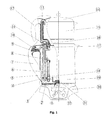
Fig. 1 demonstrates a cross-sectional view of the tea apparatus according to the present invention. -
Fig. 2a and 2b demonstrate cross-sectional views of the bidirectional valve selectively allowing water transfer to the upper receptacle according to the present invention. -
Fig. 3a and 3b demonstrate the evacuation conduit and the inlet conduit in different positions of the valve according to the present invention. -
Fig. 4 demonstrates configuration of the greater wattage resistance with respect to the lower wattage resistance according to the present invention. - Referring now to the figures outlined above, the present invention proposes an electrical household appliance for preparing tea in a traditional manner, i.e. by way of using separate boiling and brewing receptacles (respectively 19 and 15). The appliance comprises a first receptacle (19) for boiling water prior to brewing and a second receptacle (15) in which tea leaves are placed and brewed in hot water accordingly.
- Both receptacles (19, 15) are put one above another to allow thermal communication and heat energy radiated from a heat source in communication with said first receptacle (19) also reach said second receptacle (15). The base of said second receptacle (15) therefore covers the open upper end of said first receptacle (19) in a conventional manner.
- The heating arrangement of the tea preparation apparatus comprises a first electrical heating means (3) having a greater resistance with respect to a second electrical heating means (4) with a lower active power dissipation.
- As is generally practiced in the available art, effective power consumption by said heat source is lowered during brewing. Temperature in the lower receptacle may be controlled by means of a plurality of control arrangements and sensors; that is while temperature in the lower receptacle (19) may be kept in a near-boiling temperature, different control schemes to allow continuous or discontinuous powering of the heat source can be applied.
- Referring to
Fig. 1 , the lower receptacle (19) according to the present invention comprises a handle (7) joined to the lower receptacle (19) body. The machine conventionally comprises a steam switch (10) and a steam switch button (9). The apparatus can typically be set to boiling mode by said steam switch button (9). - The upper receptacle comprises a lid (14) and a handle (12) as seen in
Fig. 1 . The lower receptacle (19) according to the present invention is connected to an electrical heater base (20), said base (20) comprising an electrical connector (21) associated with an electrical adaptor (1). - The tea preparing apparatus according to the invention comprises an electronic control unit (22) allowing a user start the apparatus automatically at a specified time or manually. The boiling receptacle (19) should be filled with water prior to switching the apparatus on. Automatic transfer of boiled water will be initiated only if the fluid communication from the lower receptacle (19) to the upper receptacle (15) is established as explained below.
- The upper receptacle (15) according to the present invention comprises a pusher mechanism (16) having an axial rod slidably engaged within a spring housing in which a spring (17) biases a ball against said axial rod. Said spring loaded ball in said spring housing act as bidirectional valve (11) selectively establishing fluid communication with said upper receptacle (15) or teapot (15).
- When said upper receptacle (15) is appropriately positioned on top of said lower receptacle (19), a fluid communication is established between a boiler evacuation conduit (5) and an intake orifice equipped with said pusher mechanism (16) of a teapot (15) conduit (13). Said teapot (15) conduit (13) therefore provides that boiled water is poured out of its vent down, on top of tea leaves lying on the ground of the receptacle (15). As seen in
Fig. 2b , in the absence of the teapot (15) appropriately positioned with its pusher mechanism (16) having engaging relationship with said bidirectional valve (11), said bidirectional valve (11)'s ball joint is freely pushed up by said helical spring (17) such that boiled water rising due to siphon action in said evacuation conduit (5) is conveyed from said conduit's (5) upper end back to the lower receptacle (19) passing through said spring (17). - The initiation of the siphon action allowing transfer of boiled water to said teapot (15) as explained above is controlled as to the temperature of the water to be transferred as this is believed to be crucial in the flavor of the brewed tea.
- Hot water, flowing into an inlet conduit (6) from an inlet of said inlet conduit (6) advances down the conduit (6) and reaches an evacuation conduit (5) though a intermediary conduit (2) perimetrically lying on the ground of the lower receptacle (19). Flow of water in the reverse direction is blocked by a valve (18) downstream said inlet conduit (6).
Fig. 4 demonstrates said evacuation conduit (6) and said inlet conduit (6) extending perpendicular in the direction of said upper receptacle (15) with respect to said intermediary conduit's (2) plane parallel to the ground of said lower receptacle (19). -
Fig. 4 also demonstrate configuration of the greater wattage resistance (3) with respect to the lower wattage resistance (4). The greater wattage resistance (3) is encircled by the perimetrically extending lower wattage resistance (4), which is disposed directly on top of said intermediary conduit (2). - When water in the lower receptacle (19) is boiled, said steam switch (10) activates "keep warm" mode and power is only supplied to said lower wattage resistance (4) instead of said greater wattage resistance (3).
- Said lower wattage resistance (4) is disposed directly on top of said intermediary conduit (2), the latter perimetrically lying on the ground of the lower receptacle (19). To this end, water flowing from said inlet conduit (6) to said intermediary conduit (2) is continually heated by said greater wattage resistance (3), which is not in direct contact with said intermediary conduit (2) but in the proximity of the same. Therefore, water in said intermediary conduit (2) starts producing steam, which in turn advances said valve (18) in said inlet conduit (6), thereby blocking water inflow from said lower receptacle (19) through said inlet conduit (6).
- Steam pressure while moving up said valve (18) also forces heated water up said evacuation conduit (6). Siphoning action due to steam pressure starts at around 50 °C. Subsequent to transfer of the available water in said intermediary conduit (2), pressure drops and said valve (18) is moved down thereupon so as to reinitiate water flow from said inlet conduit (6). This process continues in cycles as water in said lower receptacle (19) is being heated.
- As temperature in said lower receptacle (19) rises, water reaching said intermediary conduit (2) becomes hotter and a faster vaporization occurs such that said valve (18) is locked in blocking position much earlier than it is locked at lower temperatures, which results in smaller amounts of water allowed into said intermediary conduit (2).
- To this end, a special calibration of said valve (18) in terms of areal density, i.e. the proportion of its largest cross-section to its weight, is necessary to provide water transfer at higher temperatures, i.e. above 80 °C. A valve (18) having a greater weight than required will be inappropriate as steam pressure will not be adequate to lock it and water will return to sad lower receptacle (19) as pressure rises. On the other hand, a valve (18) having a lower weight than required will be problematic in that it will lock too early before a sufficient amount of water fills said intermediary conduit (2), thereby resulting in a substantially slowed water transfer to said upper receptacle (15).
- When water in said lower receptacle (19) is boiled, said lower wattage resistance (4) is powered instead of said greater wattage resistance (3). When siphoning action starts, the temperature in said lower receptacle (19) is at around 50 °C and due to the fine calibration of said valve (18) in terms of areal density, water transfer to the upper receptacle (15) can continuously be effected and temperature in said upper receptacle (15) in which tea leaves are present, is adequately high, i.e. reaches as high as 90 to 94 °C.
- The areal density of said valve (18) is measured in mm2/gram as the proportion of the largest cross-section of said valve (18) in said inlet conduit (6) to its weight. To this end, it is established that an areal density of 0,018-0,021 mm2/gram is necessary for the desired effect, i.e. preventing said valve (18) from being locked before said intermediary conduit (2) is filled with water and preventing said valve (18) from being too heavy for steam pressure to be able to lock it. Said inlet conduit (6) portion around said valve (18) is in cylindrical form, i.e. has a longitudinally constant cross-section around said valve (18). A mechanical filter (8) may be arranged at the inlet of said inlet conduit (6).
- In a nutshell, the present invention proposes an electrical household appliance comprising a first receptacle (19) for boiling water and a second receptacle (15) in thermal communication with said first receptacle (19) and in which plant leaves are placed in heated water for brewing. Said second receptacle (15) is also suitable for placing on top of said first receptacle (19) such that the base of said second receptacle (15) cover the upper open end of said first receptacle (19). Said first receptacle (19) comprises a bidirectional valve (11) selectively establishing fluid communication with said second receptacle (15) in response to presence of a pusher mechanism (16) of said first receptacle (15) in engaging relationship with said bidirectional valve (11). Said first receptacle (19) further comprises an inlet conduit (6) in liquid communication with said lower receptacle (19) and is connected to an evacuation conduit (5) whose end leads to said bidirectional valve (11). Said inlet conduit (6) comprises a valve (18) having an areal density of 0,018-0,021 mm2/gram.
Claims (7)
- An electrical household appliance comprising a first receptacle (19) for boiling water and a second receptacle (15) in thermal communication with said first receptacle (19) and in which plant leaves are placed in heated water for brewing, said second receptacle (15) also being suitable for placing on top of said first receptacle (19) such that the base of said second receptacle (15) cover the upper open end of said first receptacle (19) wherein
said first receptacle (19) comprises a bidirectional valve (11) selectively establishing fluid communication with said second receptacle (15) in response to presence of a pusher mechanism (16) of said second receptacle (15) in engaging relationship with said bidirectional valve (11) and
said first receptacle (19) further comprises an inlet conduit (6) in liquid communication with said lower receptacle (19) and is connected to an evacuation conduit (5) whose end leads to said bidirectional valve (11) characterized in that,
said inlet conduit (6) comprises a valve (18) having an areal density of 0,018-0,021 mm2/gram. - An electrical household appliance as set forth in Claim 1 wherein said pusher mechanism (16) has a rod slidably engaged within a spring housing of said bidirectional valve (11) in which a spring (17) biases a ball against said rod.
- An electrical household appliance as set forth in Claim 1 or 2 wherein said bidirectional valve (11) conveys heated water back to said first receptacle (19) in response to the absence of said pusher mechanism (16) of said second receptacle (15)
- An electrical household appliance as set forth in Claim 1 wherein said inlet conduit (6) is connected to said evacuation conduit (5) though an intermediary conduit (2) perimetrically lying on the ground of said lower receptacle (19).
- An electrical household appliance as set forth in Claim 1 or 4 wherein said evacuation conduit (5) and said inlet conduit (6) extend perpendicular with respect to said intermediary conduit's (2) plane parallel to the ground of said lower receptacle (19).
- An electrical household appliance as set forth in any of previous claims wherein said appliance comprises a first electrical heating means (3) having a greater resistance with respect to a second electrical heating means (4) with a lower resistance.
- An electrical household appliance as set forth in Claim 6 wherein said greater wattage resistance (3) is encircled by the perimetrically extending lower wattage resistance below which said intermediary conduit (2) is disposed.
Priority Applications (2)
| Application Number | Priority Date | Filing Date | Title |
|---|---|---|---|
| EP11153262.8A EP2484251B1 (en) | 2011-02-03 | 2011-02-03 | Double receptacle fully automated tea machine with temperature regulation valve |
| EA201270133A EA022929B1 (en) | 2011-02-03 | 2012-02-03 | Household electrical appliance |
Applications Claiming Priority (1)
| Application Number | Priority Date | Filing Date | Title |
|---|---|---|---|
| EP11153262.8A EP2484251B1 (en) | 2011-02-03 | 2011-02-03 | Double receptacle fully automated tea machine with temperature regulation valve |
Publications (2)
| Publication Number | Publication Date |
|---|---|
| EP2484251A1 EP2484251A1 (en) | 2012-08-08 |
| EP2484251B1 true EP2484251B1 (en) | 2013-08-28 |
Family
ID=44261764
Family Applications (1)
| Application Number | Title | Priority Date | Filing Date |
|---|---|---|---|
| EP11153262.8A Not-in-force EP2484251B1 (en) | 2011-02-03 | 2011-02-03 | Double receptacle fully automated tea machine with temperature regulation valve |
Country Status (2)
| Country | Link |
|---|---|
| EP (1) | EP2484251B1 (en) |
| EA (1) | EA022929B1 (en) |
Families Citing this family (2)
| Publication number | Priority date | Publication date | Assignee | Title |
|---|---|---|---|---|
| CN104023602A (en) * | 2011-12-26 | 2014-09-03 | 阿塞里克股份有限公司 | A hot beverage preparation machine |
| WO2014101939A1 (en) * | 2012-12-27 | 2014-07-03 | Arcelik Anonim Sirketi | Fully automated tea preperation apparatus with advanced control |
Family Cites Families (3)
| Publication number | Priority date | Publication date | Assignee | Title |
|---|---|---|---|---|
| US4361750A (en) * | 1980-08-28 | 1982-11-30 | General Electric Company | Drip coffeemaker having a condenser eliminating delivery of steam to the water spreader |
| US4744291A (en) * | 1982-01-26 | 1988-05-17 | Hamilton Beach Inc. | Electric coffee maker |
| TR200800957A2 (en) * | 2008-02-14 | 2009-09-23 | Yüksel Erol | Kettle |
-
2011
- 2011-02-03 EP EP11153262.8A patent/EP2484251B1/en not_active Not-in-force
-
2012
- 2012-02-03 EA EA201270133A patent/EA022929B1/en not_active IP Right Cessation
Also Published As
| Publication number | Publication date |
|---|---|
| EA022929B1 (en) | 2016-03-31 |
| EA201270133A2 (en) | 2012-10-30 |
| EP2484251A1 (en) | 2012-08-08 |
| EA201270133A3 (en) | 2013-02-28 |
Similar Documents
| Publication | Publication Date | Title |
|---|---|---|
| CN105832121A (en) | Rice draining cooking technology | |
| WO2014076192A2 (en) | Automated turkish coffee machine with encapsulated coffee housing and comprising removable coffee preparation medium | |
| WO2010094945A2 (en) | Liquid heating appliances | |
| US4208957A (en) | Automatic filter-type coffee maker | |
| EP2484251B1 (en) | Double receptacle fully automated tea machine with temperature regulation valve | |
| WO2004110225A1 (en) | A jug, an electrothermal jug and an electrothermal jug without wire for cooking beverage | |
| CN205433366U (en) | Multifunctional coffee machine | |
| JP2019076678A (en) | Electric coffee maker | |
| EP2407067B1 (en) | Mechanical thermostat double receptacle fully automated tea machine | |
| EP2415374B1 (en) | Double container automated tea apparatus having a pump | |
| CN204813352U (en) | Rice rice steamer meal that drips evaporates rice cooker | |
| EP2543288B1 (en) | Double receptacle fully automated tea machine | |
| WO2014101954A1 (en) | A fully automated thermally efficient compact tea preperation apparatus | |
| US10555637B2 (en) | Brewer with temperature responsive control valve | |
| KR101393742B1 (en) | Coffee Machine Combined with Wireless Pot | |
| CN205671929U (en) | Rice steaming rice cooker is dripped without food steamer | |
| EP2589320A1 (en) | Fully automated tea machine with integrally disposed brewing chamber | |
| EP2938232B1 (en) | Fully automated tea preperation apparatus with advanced control | |
| CN1803076A (en) | Drink kettle convenient for changing foodstuff | |
| EP2589323A1 (en) | Fully automated tea machine | |
| CN208798976U (en) | A kind of tea set of drinking tea of temperature-adjustable | |
| CN206700019U (en) | A kind of new drip-type coffee kettle | |
| JPH0236089B2 (en) | ||
| JPH0669420B2 (en) | Electric pot | |
| JPH0532018Y2 (en) |
Legal Events
| Date | Code | Title | Description |
|---|---|---|---|
| PUAI | Public reference made under article 153(3) epc to a published international application that has entered the european phase |
Free format text: ORIGINAL CODE: 0009012 |
|
| AK | Designated contracting states |
Kind code of ref document: A1 Designated state(s): AL AT BE BG CH CY CZ DE DK EE ES FI FR GB GR HR HU IE IS IT LI LT LU LV MC MK MT NL NO PL PT RO RS SE SI SK SM TR |
|
| AX | Request for extension of the european patent |
Extension state: BA ME |
|
| REG | Reference to a national code |
Ref country code: DE Ref legal event code: R079 Ref document number: 602011002753 Country of ref document: DE Free format text: PREVIOUS MAIN CLASS: A47J0031100000 Ipc: A47J0031057000 |
|
| GRAP | Despatch of communication of intention to grant a patent |
Free format text: ORIGINAL CODE: EPIDOSNIGR1 |
|
| 17P | Request for examination filed |
Effective date: 20130204 |
|
| RIC1 | Information provided on ipc code assigned before grant |
Ipc: A47J 31/46 20060101ALI20130228BHEP Ipc: A47J 31/10 20060101AFI20130228BHEP Ipc: A47J 31/18 20060101ALI20130228BHEP |
|
| RIC1 | Information provided on ipc code assigned before grant |
Ipc: A47J 31/46 20060101ALI20130304BHEP Ipc: A47J 31/057 20060101AFI20130304BHEP Ipc: A47J 31/10 20060101ALI20130304BHEP Ipc: A47J 31/18 20060101ALI20130304BHEP |
|
| RIN1 | Information on inventor provided before grant (corrected) |
Inventor name: TAHINCIOGLU, BESIM |
|
| GRAS | Grant fee paid |
Free format text: ORIGINAL CODE: EPIDOSNIGR3 |
|
| GRAA | (expected) grant |
Free format text: ORIGINAL CODE: 0009210 |
|
| AK | Designated contracting states |
Kind code of ref document: B1 Designated state(s): AL AT BE BG CH CY CZ DE DK EE ES FI FR GB GR HR HU IE IS IT LI LT LU LV MC MK MT NL NO PL PT RO RS SE SI SK SM TR |
|
| REG | Reference to a national code |
Ref country code: GB Ref legal event code: FG4D |
|
| REG | Reference to a national code |
Ref country code: CH Ref legal event code: EP |
|
| REG | Reference to a national code |
Ref country code: AT Ref legal event code: REF Ref document number: 628824 Country of ref document: AT Kind code of ref document: T Effective date: 20130915 |
|
| REG | Reference to a national code |
Ref country code: IE Ref legal event code: FG4D |
|
| REG | Reference to a national code |
Ref country code: DE Ref legal event code: R096 Ref document number: 602011002753 Country of ref document: DE Effective date: 20131024 |
|
| REG | Reference to a national code |
Ref country code: AT Ref legal event code: MK05 Ref document number: 628824 Country of ref document: AT Kind code of ref document: T Effective date: 20130828 |
|
| REG | Reference to a national code |
Ref country code: LT Ref legal event code: MG4D |
|
| REG | Reference to a national code |
Ref country code: NL Ref legal event code: VDEP Effective date: 20130828 |
|
| PG25 | Lapsed in a contracting state [announced via postgrant information from national office to epo] |
Ref country code: HR Free format text: LAPSE BECAUSE OF FAILURE TO SUBMIT A TRANSLATION OF THE DESCRIPTION OR TO PAY THE FEE WITHIN THE PRESCRIBED TIME-LIMIT Effective date: 20130828 Ref country code: AT Free format text: LAPSE BECAUSE OF FAILURE TO SUBMIT A TRANSLATION OF THE DESCRIPTION OR TO PAY THE FEE WITHIN THE PRESCRIBED TIME-LIMIT Effective date: 20130828 Ref country code: LT Free format text: LAPSE BECAUSE OF FAILURE TO SUBMIT A TRANSLATION OF THE DESCRIPTION OR TO PAY THE FEE WITHIN THE PRESCRIBED TIME-LIMIT Effective date: 20130828 Ref country code: PT Free format text: LAPSE BECAUSE OF FAILURE TO SUBMIT A TRANSLATION OF THE DESCRIPTION OR TO PAY THE FEE WITHIN THE PRESCRIBED TIME-LIMIT Effective date: 20131230 Ref country code: IS Free format text: LAPSE BECAUSE OF FAILURE TO SUBMIT A TRANSLATION OF THE DESCRIPTION OR TO PAY THE FEE WITHIN THE PRESCRIBED TIME-LIMIT Effective date: 20131228 Ref country code: CY Free format text: LAPSE BECAUSE OF FAILURE TO SUBMIT A TRANSLATION OF THE DESCRIPTION OR TO PAY THE FEE WITHIN THE PRESCRIBED TIME-LIMIT Effective date: 20130904 Ref country code: NO Free format text: LAPSE BECAUSE OF FAILURE TO SUBMIT A TRANSLATION OF THE DESCRIPTION OR TO PAY THE FEE WITHIN THE PRESCRIBED TIME-LIMIT Effective date: 20131128 Ref country code: SE Free format text: LAPSE BECAUSE OF FAILURE TO SUBMIT A TRANSLATION OF THE DESCRIPTION OR TO PAY THE FEE WITHIN THE PRESCRIBED TIME-LIMIT Effective date: 20130828 |
|
| REG | Reference to a national code |
Ref country code: NL Ref legal event code: VDEP Effective date: 20130828 |
|
| PG25 | Lapsed in a contracting state [announced via postgrant information from national office to epo] |
Ref country code: FI Free format text: LAPSE BECAUSE OF FAILURE TO SUBMIT A TRANSLATION OF THE DESCRIPTION OR TO PAY THE FEE WITHIN THE PRESCRIBED TIME-LIMIT Effective date: 20130828 Ref country code: PL Free format text: LAPSE BECAUSE OF FAILURE TO SUBMIT A TRANSLATION OF THE DESCRIPTION OR TO PAY THE FEE WITHIN THE PRESCRIBED TIME-LIMIT Effective date: 20130828 Ref country code: BE Free format text: LAPSE BECAUSE OF FAILURE TO SUBMIT A TRANSLATION OF THE DESCRIPTION OR TO PAY THE FEE WITHIN THE PRESCRIBED TIME-LIMIT Effective date: 20130828 Ref country code: GR Free format text: LAPSE BECAUSE OF FAILURE TO SUBMIT A TRANSLATION OF THE DESCRIPTION OR TO PAY THE FEE WITHIN THE PRESCRIBED TIME-LIMIT Effective date: 20131129 Ref country code: LV Free format text: LAPSE BECAUSE OF FAILURE TO SUBMIT A TRANSLATION OF THE DESCRIPTION OR TO PAY THE FEE WITHIN THE PRESCRIBED TIME-LIMIT Effective date: 20130828 Ref country code: SI Free format text: LAPSE BECAUSE OF FAILURE TO SUBMIT A TRANSLATION OF THE DESCRIPTION OR TO PAY THE FEE WITHIN THE PRESCRIBED TIME-LIMIT Effective date: 20130828 |
|
| PG25 | Lapsed in a contracting state [announced via postgrant information from national office to epo] |
Ref country code: CY Free format text: LAPSE BECAUSE OF FAILURE TO SUBMIT A TRANSLATION OF THE DESCRIPTION OR TO PAY THE FEE WITHIN THE PRESCRIBED TIME-LIMIT Effective date: 20130828 |
|
| PG25 | Lapsed in a contracting state [announced via postgrant information from national office to epo] |
Ref country code: DK Free format text: LAPSE BECAUSE OF FAILURE TO SUBMIT A TRANSLATION OF THE DESCRIPTION OR TO PAY THE FEE WITHIN THE PRESCRIBED TIME-LIMIT Effective date: 20130828 Ref country code: NL Free format text: LAPSE BECAUSE OF FAILURE TO SUBMIT A TRANSLATION OF THE DESCRIPTION OR TO PAY THE FEE WITHIN THE PRESCRIBED TIME-LIMIT Effective date: 20130828 Ref country code: RO Free format text: LAPSE BECAUSE OF FAILURE TO SUBMIT A TRANSLATION OF THE DESCRIPTION OR TO PAY THE FEE WITHIN THE PRESCRIBED TIME-LIMIT Effective date: 20130828 Ref country code: SK Free format text: LAPSE BECAUSE OF FAILURE TO SUBMIT A TRANSLATION OF THE DESCRIPTION OR TO PAY THE FEE WITHIN THE PRESCRIBED TIME-LIMIT Effective date: 20130828 Ref country code: EE Free format text: LAPSE BECAUSE OF FAILURE TO SUBMIT A TRANSLATION OF THE DESCRIPTION OR TO PAY THE FEE WITHIN THE PRESCRIBED TIME-LIMIT Effective date: 20130828 Ref country code: CZ Free format text: LAPSE BECAUSE OF FAILURE TO SUBMIT A TRANSLATION OF THE DESCRIPTION OR TO PAY THE FEE WITHIN THE PRESCRIBED TIME-LIMIT Effective date: 20130828 |
|
| PG25 | Lapsed in a contracting state [announced via postgrant information from national office to epo] |
Ref country code: IT Free format text: LAPSE BECAUSE OF FAILURE TO SUBMIT A TRANSLATION OF THE DESCRIPTION OR TO PAY THE FEE WITHIN THE PRESCRIBED TIME-LIMIT Effective date: 20130828 Ref country code: ES Free format text: LAPSE BECAUSE OF FAILURE TO SUBMIT A TRANSLATION OF THE DESCRIPTION OR TO PAY THE FEE WITHIN THE PRESCRIBED TIME-LIMIT Effective date: 20130828 |
|
| REG | Reference to a national code |
Ref country code: DE Ref legal event code: R097 Ref document number: 602011002753 Country of ref document: DE |
|
| PLBE | No opposition filed within time limit |
Free format text: ORIGINAL CODE: 0009261 |
|
| STAA | Information on the status of an ep patent application or granted ep patent |
Free format text: STATUS: NO OPPOSITION FILED WITHIN TIME LIMIT |
|
| 26N | No opposition filed |
Effective date: 20140530 |
|
| REG | Reference to a national code |
Ref country code: DE Ref legal event code: R097 Ref document number: 602011002753 Country of ref document: DE Effective date: 20140530 |
|
| PG25 | Lapsed in a contracting state [announced via postgrant information from national office to epo] |
Ref country code: LU Free format text: LAPSE BECAUSE OF FAILURE TO SUBMIT A TRANSLATION OF THE DESCRIPTION OR TO PAY THE FEE WITHIN THE PRESCRIBED TIME-LIMIT Effective date: 20140203 Ref country code: MC Free format text: LAPSE BECAUSE OF FAILURE TO SUBMIT A TRANSLATION OF THE DESCRIPTION OR TO PAY THE FEE WITHIN THE PRESCRIBED TIME-LIMIT Effective date: 20130828 |
|
| REG | Reference to a national code |
Ref country code: CH Ref legal event code: PL |
|
| PG25 | Lapsed in a contracting state [announced via postgrant information from national office to epo] |
Ref country code: LI Free format text: LAPSE BECAUSE OF NON-PAYMENT OF DUE FEES Effective date: 20140228 Ref country code: CH Free format text: LAPSE BECAUSE OF NON-PAYMENT OF DUE FEES Effective date: 20140228 |
|
| REG | Reference to a national code |
Ref country code: FR Ref legal event code: ST Effective date: 20141031 |
|
| REG | Reference to a national code |
Ref country code: IE Ref legal event code: MM4A |
|
| PG25 | Lapsed in a contracting state [announced via postgrant information from national office to epo] |
Ref country code: FR Free format text: LAPSE BECAUSE OF NON-PAYMENT OF DUE FEES Effective date: 20140228 Ref country code: IE Free format text: LAPSE BECAUSE OF NON-PAYMENT OF DUE FEES Effective date: 20140203 |
|
| GBPC | Gb: european patent ceased through non-payment of renewal fee |
Effective date: 20150203 |
|
| PG25 | Lapsed in a contracting state [announced via postgrant information from national office to epo] |
Ref country code: GB Free format text: LAPSE BECAUSE OF NON-PAYMENT OF DUE FEES Effective date: 20150203 |
|
| PG25 | Lapsed in a contracting state [announced via postgrant information from national office to epo] |
Ref country code: MT Free format text: LAPSE BECAUSE OF FAILURE TO SUBMIT A TRANSLATION OF THE DESCRIPTION OR TO PAY THE FEE WITHIN THE PRESCRIBED TIME-LIMIT Effective date: 20130828 |
|
| PG25 | Lapsed in a contracting state [announced via postgrant information from national office to epo] |
Ref country code: SM Free format text: LAPSE BECAUSE OF FAILURE TO SUBMIT A TRANSLATION OF THE DESCRIPTION OR TO PAY THE FEE WITHIN THE PRESCRIBED TIME-LIMIT Effective date: 20130828 |
|
| PGFP | Annual fee paid to national office [announced via postgrant information from national office to epo] |
Ref country code: DE Payment date: 20160224 Year of fee payment: 6 |
|
| PG25 | Lapsed in a contracting state [announced via postgrant information from national office to epo] |
Ref country code: RS Free format text: LAPSE BECAUSE OF NON-PAYMENT OF DUE FEES Effective date: 20130828 Ref country code: BG Free format text: LAPSE BECAUSE OF FAILURE TO SUBMIT A TRANSLATION OF THE DESCRIPTION OR TO PAY THE FEE WITHIN THE PRESCRIBED TIME-LIMIT Effective date: 20130828 |
|
| PG25 | Lapsed in a contracting state [announced via postgrant information from national office to epo] |
Ref country code: HU Free format text: LAPSE BECAUSE OF FAILURE TO SUBMIT A TRANSLATION OF THE DESCRIPTION OR TO PAY THE FEE WITHIN THE PRESCRIBED TIME-LIMIT; INVALID AB INITIO Effective date: 20110203 |
|
| REG | Reference to a national code |
Ref country code: DE Ref legal event code: R119 Ref document number: 602011002753 Country of ref document: DE |
|
| PG25 | Lapsed in a contracting state [announced via postgrant information from national office to epo] |
Ref country code: DE Free format text: LAPSE BECAUSE OF NON-PAYMENT OF DUE FEES Effective date: 20170901 |
|
| PGFP | Annual fee paid to national office [announced via postgrant information from national office to epo] |
Ref country code: TR Payment date: 20180124 Year of fee payment: 8 |
|
| PG25 | Lapsed in a contracting state [announced via postgrant information from national office to epo] |
Ref country code: MK Free format text: LAPSE BECAUSE OF FAILURE TO SUBMIT A TRANSLATION OF THE DESCRIPTION OR TO PAY THE FEE WITHIN THE PRESCRIBED TIME-LIMIT Effective date: 20130828 |
|
| PG25 | Lapsed in a contracting state [announced via postgrant information from national office to epo] |
Ref country code: AL Free format text: LAPSE BECAUSE OF FAILURE TO SUBMIT A TRANSLATION OF THE DESCRIPTION OR TO PAY THE FEE WITHIN THE PRESCRIBED TIME-LIMIT Effective date: 20130828 |
|
| PG25 | Lapsed in a contracting state [announced via postgrant information from national office to epo] |
Ref country code: TR Free format text: LAPSE BECAUSE OF NON-PAYMENT OF DUE FEES Effective date: 20190203 |