EP2482881B1 - A mechanism for a drug delivery device - Google Patents
A mechanism for a drug delivery device Download PDFInfo
- Publication number
- EP2482881B1 EP2482881B1 EP10766248.8A EP10766248A EP2482881B1 EP 2482881 B1 EP2482881 B1 EP 2482881B1 EP 10766248 A EP10766248 A EP 10766248A EP 2482881 B1 EP2482881 B1 EP 2482881B1
- Authority
- EP
- European Patent Office
- Prior art keywords
- assembly
- cartridge
- assembly according
- adjustment
- bung
- Prior art date
- Legal status (The legal status is an assumption and is not a legal conclusion. Google has not performed a legal analysis and makes no representation as to the accuracy of the status listed.)
- Active
Links
- 238000012377 drug delivery Methods 0.000 title claims description 39
- 229940126601 medicinal product Drugs 0.000 claims description 24
- 239000003814 drug Substances 0.000 claims description 22
- 239000012530 fluid Substances 0.000 claims description 20
- 238000000034 method Methods 0.000 claims description 6
- 238000006073 displacement reaction Methods 0.000 claims description 3
- 230000008878 coupling Effects 0.000 claims 1
- 238000010168 coupling process Methods 0.000 claims 1
- 238000005859 coupling reaction Methods 0.000 claims 1
- JUFFVKRROAPVBI-PVOYSMBESA-N chembl1210015 Chemical compound C([C@@H](C(=O)N[C@@H]([C@@H](C)CC)C(=O)N[C@@H](CCC(O)=O)C(=O)N[C@@H](CC=1C2=CC=CC=C2NC=1)C(=O)N[C@@H](CC(C)C)C(=O)N[C@@H](CCCCN)C(=O)N[C@@H](CC(=O)N[C@H]1[C@@H]([C@@H](O)[C@H](O[C@H]2[C@@H]([C@@H](O)[C@@H](O)[C@@H](CO[C@]3(O[C@@H](C[C@H](O)[C@H](O)CO)[C@H](NC(C)=O)[C@@H](O)C3)C(O)=O)O2)O)[C@@H](CO)O1)NC(C)=O)C(=O)NCC(=O)NCC(=O)N1[C@@H](CCC1)C(=O)N[C@@H](CO)C(=O)N[C@@H](CO)C(=O)NCC(=O)N[C@@H](C)C(=O)N1[C@@H](CCC1)C(=O)N1[C@@H](CCC1)C(=O)N1[C@@H](CCC1)C(=O)N[C@@H](CO)C(N)=O)NC(=O)[C@H](CC(C)C)NC(=O)[C@H](CCCNC(N)=N)NC(=O)[C@@H](NC(=O)[C@H](C)NC(=O)[C@H](CCC(O)=O)NC(=O)[C@H](CCC(O)=O)NC(=O)[C@H](CCC(O)=O)NC(=O)[C@H](CCSC)NC(=O)[C@H](CCC(N)=O)NC(=O)[C@H](CCCCN)NC(=O)[C@H](CO)NC(=O)[C@H](CC(C)C)NC(=O)[C@H](CC(O)=O)NC(=O)[C@H](CO)NC(=O)[C@@H](NC(=O)[C@H](CC=1C=CC=CC=1)NC(=O)[C@@H](NC(=O)CNC(=O)[C@H](CCC(O)=O)NC(=O)CNC(=O)[C@@H](N)CC=1NC=NC=1)[C@@H](C)O)[C@@H](C)O)C(C)C)C1=CC=CC=C1 JUFFVKRROAPVBI-PVOYSMBESA-N 0.000 description 50
- 108010011459 Exenatide Proteins 0.000 description 47
- 229960001519 exenatide Drugs 0.000 description 47
- 101000976075 Homo sapiens Insulin Proteins 0.000 description 22
- QEFRNWWLZKMPFJ-YGVKFDHGSA-N L-methionine S-oxide Chemical compound CS(=O)CC[C@H](N)C(O)=O QEFRNWWLZKMPFJ-YGVKFDHGSA-N 0.000 description 22
- PBGKTOXHQIOBKM-FHFVDXKLSA-N insulin (human) Chemical compound C([C@@H](C(=O)N[C@@H](CC(C)C)C(=O)N[C@H]1CSSC[C@H]2C(=O)N[C@H](C(=O)N[C@@H](CO)C(=O)N[C@H](C(=O)N[C@H](C(N[C@@H](CO)C(=O)N[C@@H](CC(C)C)C(=O)N[C@@H](CC=3C=CC(O)=CC=3)C(=O)N[C@@H](CCC(N)=O)C(=O)N[C@@H](CC(C)C)C(=O)N[C@@H](CCC(O)=O)C(=O)N[C@@H](CC(N)=O)C(=O)N[C@@H](CC=3C=CC(O)=CC=3)C(=O)N[C@@H](CSSC[C@H](NC(=O)[C@H](C(C)C)NC(=O)[C@H](CC(C)C)NC(=O)[C@H](CC=3C=CC(O)=CC=3)NC(=O)[C@H](CC(C)C)NC(=O)[C@H](C)NC(=O)[C@H](CCC(O)=O)NC(=O)[C@H](C(C)C)NC(=O)[C@H](CC(C)C)NC(=O)[C@H](CC=3NC=NC=3)NC(=O)[C@H](CO)NC(=O)CNC1=O)C(=O)NCC(=O)N[C@@H](CCC(O)=O)C(=O)N[C@@H](CCCNC(N)=N)C(=O)NCC(=O)N[C@@H](CC=1C=CC=CC=1)C(=O)N[C@@H](CC=1C=CC=CC=1)C(=O)N[C@@H](CC=1C=CC(O)=CC=1)C(=O)N[C@@H]([C@@H](C)O)C(=O)N1[C@@H](CCC1)C(=O)N[C@@H](CCCCN)C(=O)N[C@@H]([C@@H](C)O)C(O)=O)C(=O)N[C@@H](CC(N)=O)C(O)=O)=O)CSSC[C@@H](C(N2)=O)NC(=O)[C@H](CCC(N)=O)NC(=O)[C@H](CCC(O)=O)NC(=O)[C@H](C(C)C)NC(=O)[C@@H](NC(=O)CN)[C@@H](C)CC)[C@@H](C)CC)[C@@H](C)O)NC(=O)[C@H](CCC(N)=O)NC(=O)[C@H](CC(N)=O)NC(=O)[C@@H](NC(=O)[C@@H](N)CC=1C=CC=CC=1)C(C)C)C1=CN=CN1 PBGKTOXHQIOBKM-FHFVDXKLSA-N 0.000 description 21
- 150000003839 salts Chemical class 0.000 description 8
- 150000001875 compounds Chemical class 0.000 description 7
- NOESYZHRGYRDHS-UHFFFAOYSA-N insulin Chemical compound N1C(=O)C(NC(=O)C(CCC(N)=O)NC(=O)C(CCC(O)=O)NC(=O)C(C(C)C)NC(=O)C(NC(=O)CN)C(C)CC)CSSCC(C(NC(CO)C(=O)NC(CC(C)C)C(=O)NC(CC=2C=CC(O)=CC=2)C(=O)NC(CCC(N)=O)C(=O)NC(CC(C)C)C(=O)NC(CCC(O)=O)C(=O)NC(CC(N)=O)C(=O)NC(CC=2C=CC(O)=CC=2)C(=O)NC(CSSCC(NC(=O)C(C(C)C)NC(=O)C(CC(C)C)NC(=O)C(CC=2C=CC(O)=CC=2)NC(=O)C(CC(C)C)NC(=O)C(C)NC(=O)C(CCC(O)=O)NC(=O)C(C(C)C)NC(=O)C(CC(C)C)NC(=O)C(CC=2NC=NC=2)NC(=O)C(CO)NC(=O)CNC2=O)C(=O)NCC(=O)NC(CCC(O)=O)C(=O)NC(CCCNC(N)=N)C(=O)NCC(=O)NC(CC=3C=CC=CC=3)C(=O)NC(CC=3C=CC=CC=3)C(=O)NC(CC=3C=CC(O)=CC=3)C(=O)NC(C(C)O)C(=O)N3C(CCC3)C(=O)NC(CCCCN)C(=O)NC(C)C(O)=O)C(=O)NC(CC(N)=O)C(O)=O)=O)NC(=O)C(C(C)CC)NC(=O)C(CO)NC(=O)C(C(C)O)NC(=O)C1CSSCC2NC(=O)C(CC(C)C)NC(=O)C(NC(=O)C(CCC(N)=O)NC(=O)C(CC(N)=O)NC(=O)C(NC(=O)C(N)CC=1C=CC=CC=1)C(C)C)CC1=CN=CN1 NOESYZHRGYRDHS-UHFFFAOYSA-N 0.000 description 5
- 206010012601 diabetes mellitus Diseases 0.000 description 4
- 108090000765 processed proteins & peptides Proteins 0.000 description 4
- 150000004676 glycans Chemical class 0.000 description 3
- 229940088597 hormone Drugs 0.000 description 3
- 239000005556 hormone Substances 0.000 description 3
- 239000003055 low molecular weight heparin Substances 0.000 description 3
- 229940127215 low-molecular weight heparin Drugs 0.000 description 3
- 229920001282 polysaccharide Polymers 0.000 description 3
- 239000005017 polysaccharide Substances 0.000 description 3
- 208000004476 Acute Coronary Syndrome Diseases 0.000 description 2
- 208000002249 Diabetes Complications Diseases 0.000 description 2
- 206010012689 Diabetic retinopathy Diseases 0.000 description 2
- 108010088406 Glucagon-Like Peptides Proteins 0.000 description 2
- HTTJABKRGRZYRN-UHFFFAOYSA-N Heparin Chemical compound OC1C(NC(=O)C)C(O)OC(COS(O)(=O)=O)C1OC1C(OS(O)(=O)=O)C(O)C(OC2C(C(OS(O)(=O)=O)C(OC3C(C(O)C(O)C(O3)C(O)=O)OS(O)(=O)=O)C(CO)O2)NS(O)(=O)=O)C(C(O)=O)O1 HTTJABKRGRZYRN-UHFFFAOYSA-N 0.000 description 2
- 108090001061 Insulin Proteins 0.000 description 2
- 102000004877 Insulin Human genes 0.000 description 2
- 239000002253 acid Substances 0.000 description 2
- 150000001447 alkali salts Chemical class 0.000 description 2
- 229940079593 drug Drugs 0.000 description 2
- 229960002897 heparin Drugs 0.000 description 2
- 229920000669 heparin Polymers 0.000 description 2
- 229940125396 insulin Drugs 0.000 description 2
- 230000036316 preload Effects 0.000 description 2
- 230000037452 priming Effects 0.000 description 2
- 238000011321 prophylaxis Methods 0.000 description 2
- 239000012453 solvate Substances 0.000 description 2
- 238000011282 treatment Methods 0.000 description 2
- KIUKXJAPPMFGSW-DNGZLQJQSA-N (2S,3S,4S,5R,6R)-6-[(2S,3R,4R,5S,6R)-3-Acetamido-2-[(2S,3S,4R,5R,6R)-6-[(2R,3R,4R,5S,6R)-3-acetamido-2,5-dihydroxy-6-(hydroxymethyl)oxan-4-yl]oxy-2-carboxy-4,5-dihydroxyoxan-3-yl]oxy-5-hydroxy-6-(hydroxymethyl)oxan-4-yl]oxy-3,4,5-trihydroxyoxane-2-carboxylic acid Chemical compound CC(=O)N[C@H]1[C@H](O)O[C@H](CO)[C@@H](O)[C@@H]1O[C@H]1[C@H](O)[C@@H](O)[C@H](O[C@H]2[C@@H]([C@@H](O[C@H]3[C@@H]([C@@H](O)[C@H](O)[C@H](O3)C(O)=O)O)[C@H](O)[C@@H](CO)O2)NC(C)=O)[C@@H](C(O)=O)O1 KIUKXJAPPMFGSW-DNGZLQJQSA-N 0.000 description 1
- 125000004169 (C1-C6) alkyl group Chemical group 0.000 description 1
- 125000001831 (C6-C10) heteroaryl group Chemical group 0.000 description 1
- 208000035285 Allergic Seasonal Rhinitis Diseases 0.000 description 1
- QGZKDVFQNNGYKY-UHFFFAOYSA-O Ammonium Chemical compound [NH4+] QGZKDVFQNNGYKY-UHFFFAOYSA-O 0.000 description 1
- 206010002383 Angina Pectoris Diseases 0.000 description 1
- 201000001320 Atherosclerosis Diseases 0.000 description 1
- 108010037003 Buserelin Proteins 0.000 description 1
- 125000000882 C2-C6 alkenyl group Chemical group 0.000 description 1
- 125000000041 C6-C10 aryl group Chemical group 0.000 description 1
- 108010000437 Deamino Arginine Vasopressin Proteins 0.000 description 1
- 208000005189 Embolism Diseases 0.000 description 1
- 102000004190 Enzymes Human genes 0.000 description 1
- 108090000790 Enzymes Proteins 0.000 description 1
- 102000012673 Follicle Stimulating Hormone Human genes 0.000 description 1
- 108010079345 Follicle Stimulating Hormone Proteins 0.000 description 1
- 102400000932 Gonadoliberin-1 Human genes 0.000 description 1
- 108010069236 Goserelin Proteins 0.000 description 1
- BLCLNMBMMGCOAS-URPVMXJPSA-N Goserelin Chemical compound C([C@@H](C(=O)N[C@H](COC(C)(C)C)C(=O)N[C@@H](CC(C)C)C(=O)N[C@@H](CCCN=C(N)N)C(=O)N1[C@@H](CCC1)C(=O)NNC(N)=O)NC(=O)[C@H](CO)NC(=O)[C@H](CC=1C2=CC=CC=C2NC=1)NC(=O)[C@H](CC=1NC=NC=1)NC(=O)[C@H]1NC(=O)CC1)C1=CC=C(O)C=C1 BLCLNMBMMGCOAS-URPVMXJPSA-N 0.000 description 1
- 101500026183 Homo sapiens Gonadoliberin-1 Proteins 0.000 description 1
- 102000002265 Human Growth Hormone Human genes 0.000 description 1
- 108010000521 Human Growth Hormone Proteins 0.000 description 1
- 239000000854 Human Growth Hormone Substances 0.000 description 1
- 206010061218 Inflammation Diseases 0.000 description 1
- 108010000817 Leuprolide Proteins 0.000 description 1
- 102000009151 Luteinizing Hormone Human genes 0.000 description 1
- 108010073521 Luteinizing Hormone Proteins 0.000 description 1
- 108010021717 Nafarelin Proteins 0.000 description 1
- 206010028980 Neoplasm Diseases 0.000 description 1
- 108091034117 Oligonucleotide Proteins 0.000 description 1
- ONIBWKKTOPOVIA-UHFFFAOYSA-N Proline Natural products OC(=O)C1CCCN1 ONIBWKKTOPOVIA-UHFFFAOYSA-N 0.000 description 1
- 208000010378 Pulmonary Embolism Diseases 0.000 description 1
- 108010010056 Terlipressin Proteins 0.000 description 1
- 208000001435 Thromboembolism Diseases 0.000 description 1
- 108010050144 Triptorelin Pamoate Proteins 0.000 description 1
- 239000003513 alkali Substances 0.000 description 1
- 239000005557 antagonist Substances 0.000 description 1
- 238000000429 assembly Methods 0.000 description 1
- 229960002719 buserelin Drugs 0.000 description 1
- CUWODFFVMXJOKD-UVLQAERKSA-N buserelin Chemical compound CCNC(=O)[C@@H]1CCCN1C(=O)[C@H](CCCN=C(N)N)NC(=O)[C@H](CC(C)C)NC(=O)[C@@H](COC(C)(C)C)NC(=O)[C@@H](NC(=O)[C@H](CO)NC(=O)[C@H](CC=1C2=CC=CC=C2NC=1)NC(=O)[C@H](CC=1NC=NC=1)NC(=O)[C@H]1NC(=O)CC1)CC1=CC=C(O)C=C1 CUWODFFVMXJOKD-UVLQAERKSA-N 0.000 description 1
- 201000011510 cancer Diseases 0.000 description 1
- 150000001768 cations Chemical class 0.000 description 1
- 229960004281 desmopressin Drugs 0.000 description 1
- NFLWUMRGJYTJIN-NXBWRCJVSA-N desmopressin Chemical compound C([C@H]1C(=O)N[C@H](C(N[C@@H](CC(N)=O)C(=O)N[C@@H](CSSCCC(=O)N[C@@H](CC=2C=CC(O)=CC=2)C(=O)N1)C(=O)N1[C@@H](CCC1)C(=O)N[C@@H](CCCNC(N)=N)C(=O)NCC(N)=O)=O)CCC(=O)N)C1=CC=CC=C1 NFLWUMRGJYTJIN-NXBWRCJVSA-N 0.000 description 1
- 208000037265 diseases, disorders, signs and symptoms Diseases 0.000 description 1
- 208000035475 disorder Diseases 0.000 description 1
- 229960005153 enoxaparin sodium Drugs 0.000 description 1
- 229960001442 gonadorelin Drugs 0.000 description 1
- XLXSAKCOAKORKW-AQJXLSMYSA-N gonadorelin Chemical compound C([C@@H](C(=O)NCC(=O)N[C@@H](CC(C)C)C(=O)N[C@@H](CCCNC(N)=N)C(=O)N1[C@@H](CCC1)C(=O)NCC(N)=O)NC(=O)[C@H](CO)NC(=O)[C@H](CC=1C2=CC=CC=C2NC=1)NC(=O)[C@H](CC=1N=CNC=1)NC(=O)[C@H]1NC(=O)CC1)C1=CC=C(O)C=C1 XLXSAKCOAKORKW-AQJXLSMYSA-N 0.000 description 1
- 229960002913 goserelin Drugs 0.000 description 1
- 229920002674 hyaluronan Polymers 0.000 description 1
- 229960003160 hyaluronic acid Drugs 0.000 description 1
- 150000004677 hydrates Chemical class 0.000 description 1
- 229910052739 hydrogen Inorganic materials 0.000 description 1
- 239000001257 hydrogen Substances 0.000 description 1
- 125000004435 hydrogen atom Chemical class [H]* 0.000 description 1
- 239000000960 hypophysis hormone Substances 0.000 description 1
- 210000003016 hypothalamus Anatomy 0.000 description 1
- 230000004054 inflammatory process Effects 0.000 description 1
- 239000004026 insulin derivative Substances 0.000 description 1
- 230000003993 interaction Effects 0.000 description 1
- GFIJNRVAKGFPGQ-LIJARHBVSA-N leuprolide Chemical compound CCNC(=O)[C@@H]1CCCN1C(=O)[C@H](CCCNC(N)=N)NC(=O)[C@H](CC(C)C)NC(=O)[C@@H](CC(C)C)NC(=O)[C@@H](NC(=O)[C@H](CO)NC(=O)[C@H](CC=1C2=CC=CC=C2NC=1)NC(=O)[C@H](CC=1N=CNC=1)NC(=O)[C@H]1NC(=O)CC1)CC1=CC=C(O)C=C1 GFIJNRVAKGFPGQ-LIJARHBVSA-N 0.000 description 1
- 229960004338 leuprorelin Drugs 0.000 description 1
- 208000002780 macular degeneration Diseases 0.000 description 1
- 239000000203 mixture Substances 0.000 description 1
- 208000010125 myocardial infarction Diseases 0.000 description 1
- RWHUEXWOYVBUCI-ITQXDASVSA-N nafarelin Chemical compound C([C@@H](C(=O)N[C@H](CC=1C=C2C=CC=CC2=CC=1)C(=O)N[C@@H](CC(C)C)C(=O)N[C@@H](CCCN=C(N)N)C(=O)N1[C@@H](CCC1)C(=O)NCC(N)=O)NC(=O)[C@H](CO)NC(=O)[C@H](CC=1C2=CC=CC=C2NC=1)NC(=O)[C@H](CC=1NC=NC=1)NC(=O)[C@H]1NC(=O)CC1)C1=CC=C(O)C=C1 RWHUEXWOYVBUCI-ITQXDASVSA-N 0.000 description 1
- 229960002333 nafarelin Drugs 0.000 description 1
- 239000008194 pharmaceutical composition Substances 0.000 description 1
- 102000004196 processed proteins & peptides Human genes 0.000 description 1
- 125000001500 prolyl group Chemical group [H]N1C([H])(C(=O)[*])C([H])([H])C([H])([H])C1([H])[H] 0.000 description 1
- 230000001105 regulatory effect Effects 0.000 description 1
- 206010039073 rheumatoid arthritis Diseases 0.000 description 1
- 229960004532 somatropin Drugs 0.000 description 1
- 229960003813 terlipressin Drugs 0.000 description 1
- BENFXAYNYRLAIU-QSVFAHTRSA-N terlipressin Chemical compound NCCCC[C@@H](C(=O)NCC(N)=O)NC(=O)[C@@H]1CCCN1C(=O)[C@H]1NC(=O)[C@H](CC(N)=O)NC(=O)[C@H](CCC(N)=O)NC(=O)[C@H](CC=2C=CC=CC=2)NC(=O)[C@H](CC=2C=CC(O)=CC=2)NC(=O)[C@@H](NC(=O)CNC(=O)CNC(=O)CN)CSSC1 BENFXAYNYRLAIU-QSVFAHTRSA-N 0.000 description 1
- CIJQTPFWFXOSEO-NDMITSJXSA-J tetrasodium;(2r,3r,4s)-2-[(2r,3s,4r,5r,6s)-5-acetamido-6-[(1r,2r,3r,4r)-4-[(2r,3s,4r,5r,6r)-5-acetamido-6-[(4r,5r,6r)-2-carboxylato-4,5-dihydroxy-6-[[(1r,3r,4r,5r)-3-hydroxy-4-(sulfonatoamino)-6,8-dioxabicyclo[3.2.1]octan-2-yl]oxy]oxan-3-yl]oxy-2-(hydroxy Chemical compound [Na+].[Na+].[Na+].[Na+].O([C@@H]1[C@@H](COS(O)(=O)=O)O[C@@H]([C@@H]([C@H]1O)NC(C)=O)O[C@@H]1C(C[C@H]([C@@H]([C@H]1O)O)O[C@@H]1[C@@H](CO)O[C@H](OC2C(O[C@@H](OC3[C@@H]([C@@H](NS([O-])(=O)=O)[C@@H]4OC[C@H]3O4)O)[C@H](O)[C@H]2O)C([O-])=O)[C@H](NC(C)=O)[C@H]1C)C([O-])=O)[C@@H]1OC(C([O-])=O)=C[C@H](O)[C@H]1O CIJQTPFWFXOSEO-NDMITSJXSA-J 0.000 description 1
- 229960004824 triptorelin Drugs 0.000 description 1
- VXKHXGOKWPXYNA-PGBVPBMZSA-N triptorelin Chemical compound C([C@@H](C(=O)N[C@H](CC=1C2=CC=CC=C2NC=1)C(=O)N[C@@H](CC(C)C)C(=O)N[C@@H](CCCNC(N)=N)C(=O)N1[C@@H](CCC1)C(=O)NCC(N)=O)NC(=O)[C@H](CO)NC(=O)[C@H](CC=1C2=CC=CC=C2NC=1)NC(=O)[C@H](CC=1N=CNC=1)NC(=O)[C@H]1NC(=O)CC1)C1=CC=C(O)C=C1 VXKHXGOKWPXYNA-PGBVPBMZSA-N 0.000 description 1
- 229960005486 vaccine Drugs 0.000 description 1
- 210000003462 vein Anatomy 0.000 description 1
Images

Classifications
-
- A—HUMAN NECESSITIES
- A61—MEDICAL OR VETERINARY SCIENCE; HYGIENE
- A61M—DEVICES FOR INTRODUCING MEDIA INTO, OR ONTO, THE BODY; DEVICES FOR TRANSDUCING BODY MEDIA OR FOR TAKING MEDIA FROM THE BODY; DEVICES FOR PRODUCING OR ENDING SLEEP OR STUPOR
- A61M5/00—Devices for bringing media into the body in a subcutaneous, intra-vascular or intramuscular way; Accessories therefor, e.g. filling or cleaning devices, arm-rests
- A61M5/178—Syringes
- A61M5/31—Details
- A61M5/315—Pistons; Piston-rods; Guiding, blocking or restricting the movement of the rod or piston; Appliances on the rod for facilitating dosing ; Dosing mechanisms
- A61M5/31565—Administration mechanisms, i.e. constructional features, modes of administering a dose
- A61M5/31576—Constructional features or modes of drive mechanisms for piston rods
- A61M5/31583—Constructional features or modes of drive mechanisms for piston rods based on rotational translation, i.e. movement of piston rod is caused by relative rotation between the user activated actuator and the piston rod
- A61M5/31585—Constructional features or modes of drive mechanisms for piston rods based on rotational translation, i.e. movement of piston rod is caused by relative rotation between the user activated actuator and the piston rod performed by axially moving actuator, e.g. an injection button
-
- A—HUMAN NECESSITIES
- A61—MEDICAL OR VETERINARY SCIENCE; HYGIENE
- A61M—DEVICES FOR INTRODUCING MEDIA INTO, OR ONTO, THE BODY; DEVICES FOR TRANSDUCING BODY MEDIA OR FOR TAKING MEDIA FROM THE BODY; DEVICES FOR PRODUCING OR ENDING SLEEP OR STUPOR
- A61M5/00—Devices for bringing media into the body in a subcutaneous, intra-vascular or intramuscular way; Accessories therefor, e.g. filling or cleaning devices, arm-rests
- A61M5/178—Syringes
- A61M5/24—Ampoule syringes, i.e. syringes with needle for use in combination with replaceable ampoules or carpules, e.g. automatic
-
- A—HUMAN NECESSITIES
- A61—MEDICAL OR VETERINARY SCIENCE; HYGIENE
- A61M—DEVICES FOR INTRODUCING MEDIA INTO, OR ONTO, THE BODY; DEVICES FOR TRANSDUCING BODY MEDIA OR FOR TAKING MEDIA FROM THE BODY; DEVICES FOR PRODUCING OR ENDING SLEEP OR STUPOR
- A61M5/00—Devices for bringing media into the body in a subcutaneous, intra-vascular or intramuscular way; Accessories therefor, e.g. filling or cleaning devices, arm-rests
- A61M5/178—Syringes
- A61M5/31—Details
- A61M5/315—Pistons; Piston-rods; Guiding, blocking or restricting the movement of the rod or piston; Appliances on the rod for facilitating dosing ; Dosing mechanisms
- A61M5/31533—Dosing mechanisms, i.e. setting a dose
- A61M5/31545—Setting modes for dosing
- A61M5/31548—Mechanically operated dose setting member
- A61M5/31555—Mechanically operated dose setting member by purely axial movement of dose setting member, e.g. during setting or filling of a syringe
-
- A—HUMAN NECESSITIES
- A61—MEDICAL OR VETERINARY SCIENCE; HYGIENE
- A61M—DEVICES FOR INTRODUCING MEDIA INTO, OR ONTO, THE BODY; DEVICES FOR TRANSDUCING BODY MEDIA OR FOR TAKING MEDIA FROM THE BODY; DEVICES FOR PRODUCING OR ENDING SLEEP OR STUPOR
- A61M5/00—Devices for bringing media into the body in a subcutaneous, intra-vascular or intramuscular way; Accessories therefor, e.g. filling or cleaning devices, arm-rests
- A61M5/178—Syringes
- A61M5/31—Details
- A61M5/315—Pistons; Piston-rods; Guiding, blocking or restricting the movement of the rod or piston; Appliances on the rod for facilitating dosing ; Dosing mechanisms
- A61M5/31565—Administration mechanisms, i.e. constructional features, modes of administering a dose
- A61M5/31576—Constructional features or modes of drive mechanisms for piston rods
- A61M5/31578—Constructional features or modes of drive mechanisms for piston rods based on axial translation, i.e. components directly operatively associated and axially moved with plunger rod
- A61M5/3158—Constructional features or modes of drive mechanisms for piston rods based on axial translation, i.e. components directly operatively associated and axially moved with plunger rod performed by axially moving actuator operated by user, e.g. an injection button
-
- A—HUMAN NECESSITIES
- A61—MEDICAL OR VETERINARY SCIENCE; HYGIENE
- A61M—DEVICES FOR INTRODUCING MEDIA INTO, OR ONTO, THE BODY; DEVICES FOR TRANSDUCING BODY MEDIA OR FOR TAKING MEDIA FROM THE BODY; DEVICES FOR PRODUCING OR ENDING SLEEP OR STUPOR
- A61M5/00—Devices for bringing media into the body in a subcutaneous, intra-vascular or intramuscular way; Accessories therefor, e.g. filling or cleaning devices, arm-rests
- A61M5/178—Syringes
- A61M5/24—Ampoule syringes, i.e. syringes with needle for use in combination with replaceable ampoules or carpules, e.g. automatic
- A61M2005/2403—Ampoule inserted into the ampoule holder
- A61M2005/2407—Ampoule inserted into the ampoule holder from the rear
-
- A—HUMAN NECESSITIES
- A61—MEDICAL OR VETERINARY SCIENCE; HYGIENE
- A61M—DEVICES FOR INTRODUCING MEDIA INTO, OR ONTO, THE BODY; DEVICES FOR TRANSDUCING BODY MEDIA OR FOR TAKING MEDIA FROM THE BODY; DEVICES FOR PRODUCING OR ENDING SLEEP OR STUPOR
- A61M2205/00—General characteristics of the apparatus
- A61M2205/60—General characteristics of the apparatus with identification means
- A61M2205/6063—Optical identification systems
- A61M2205/6081—Colour codes
-
- A—HUMAN NECESSITIES
- A61—MEDICAL OR VETERINARY SCIENCE; HYGIENE
- A61M—DEVICES FOR INTRODUCING MEDIA INTO, OR ONTO, THE BODY; DEVICES FOR TRANSDUCING BODY MEDIA OR FOR TAKING MEDIA FROM THE BODY; DEVICES FOR PRODUCING OR ENDING SLEEP OR STUPOR
- A61M2207/00—Methods of manufacture, assembly or production
-
- A—HUMAN NECESSITIES
- A61—MEDICAL OR VETERINARY SCIENCE; HYGIENE
- A61M—DEVICES FOR INTRODUCING MEDIA INTO, OR ONTO, THE BODY; DEVICES FOR TRANSDUCING BODY MEDIA OR FOR TAKING MEDIA FROM THE BODY; DEVICES FOR PRODUCING OR ENDING SLEEP OR STUPOR
- A61M5/00—Devices for bringing media into the body in a subcutaneous, intra-vascular or intramuscular way; Accessories therefor, e.g. filling or cleaning devices, arm-rests
- A61M5/178—Syringes
- A61M5/31—Details
- A61M5/3146—Priming, e.g. purging, reducing backlash or clearance
-
- Y—GENERAL TAGGING OF NEW TECHNOLOGICAL DEVELOPMENTS; GENERAL TAGGING OF CROSS-SECTIONAL TECHNOLOGIES SPANNING OVER SEVERAL SECTIONS OF THE IPC; TECHNICAL SUBJECTS COVERED BY FORMER USPC CROSS-REFERENCE ART COLLECTIONS [XRACs] AND DIGESTS
- Y10—TECHNICAL SUBJECTS COVERED BY FORMER USPC
- Y10T—TECHNICAL SUBJECTS COVERED BY FORMER US CLASSIFICATION
- Y10T29/00—Metal working
- Y10T29/49—Method of mechanical manufacture
- Y10T29/49826—Assembling or joining
Definitions
- the present invention relates to an assembly for use in a drug delivery device.
- Drug delivery devices are generally known for the administration of a medicinal product, for example insulin or heparin, but also for other medicinal products for self-administration by a patient. Most of the drug delivery devices are pen-type injectors, which dispense a pre-set dose of a fluid medicinal product.
- Document EP 0 058 536 A1 shows an example for a drug delivery device where a pre-set dose can be administered.
- a plunger is screwed with respect to a fixed sleeve, thereby advancing a plug in a fluid containing cylinder.
- the user Before the first use of the drug delivery device the user usually has to prime the drug delivery device. Users who are unfamiliar with such pen-type injectors may fail or incorrectly prime their drug delivery device before dispensing the first dose.
- an assembly which is forming a piston rod for advancing a cartridge bung in a drug delivery device.
- the assembly comprises a first member and a second member.
- the first and the second member are moveable with respect to each other to adjust the length of the piston rod.
- the first member is locked in position with respect to the second member in order to define a fixed length of the piston rod.
- the assembly may be set-up and may be used by a patient for the application of a medicament, which may comprise setting and dispensing a dose of a medicinal product.
- the operation of the device may be performed only once or also repeatedly.
- the assembly is used for preparative purposes only and is not suited for a set and dispense action.
- the drug delivery device can be used without the requirement for a priming dose to prepare the device first.
- the dose setting may include the step of loading the device whereas afterwards dispensing a predefined amount of medication is performed, whereas in the case of a variable dose device the step of setting includes the adjustment of the device to define the amount of medication to be dispensed in the subsequent dispensing operation.
- This arrangement may be used for fixed dose pens as well as for variable dose pens.
- the second member may comprise ratchet teeth or a lead screw as part of the related drive mechanism.
- the piston rod In case of a ratchet teeth based drive mechanism, the piston rod is linearly advanced and in case of a lead screw based drive mechanism, the piston rod is rotationally advanced.
- the first member is coupled to an adjustment member such that relative axial movement between the first member and the adjustment member is permitted and rotational movement relative to each other is prevented.
- the first member may comprise a part, which has a non-circular cross section.
- the adjustment member may comprise an aperture through which the part of the first member, which has a non-circular cross section, can extend.
- the shape of the non-circular cross section of the first member and the shape of the aperture of the adjustment member match such that relative axial movement between the first member and the adjustment member is permitted and relative rotational movement is prevented.
- the assembly comprises a distal end, where the medicinal product may be dispensed out of an assembled medicament cartridge and a proximal end, which indicates the end opposite to the distal end.
- the first member may be located within a bore along the longitudinal axis of the second member and extends beyond the proximal end of the second member.
- the adjustment member may control the rotational movement of the first member through the second member. Additionally, the location of the first member with respect to the second member may be locked by means of the adjustment member.
- the assembly comprises a threaded engagement between the first member and the second member.
- the first member may comprise an external thread, which engages with an internal thread of the distal end of the second member.
- the adjustment member is rotatable relative to the second member.
- the adjustment is intended to be undertaken during assembly of the device in the factory. Consequently, the rotation of the adjustment member may be performed by a machine. As a consequence of the rotational movement of the adjustment member, the first member is advanced through the second member.
- the threaded engagement is self-locking.
- the pitch of the threads at the first and at the second member may be chosen such that the threaded engagement is self-locking. This means that an axial displacement can not result in a rotational movement because of the low pitch and the dynamic friction between the engaged threads. Due to the self-locking threaded engagement, it is not necessary to lock the first member with the second member at the proximal end.
- the first member is at least partly arranged inside the second member.
- the first member may protrude from the distal end and from the proximal end of the second member.
- the adjustment member is arranged such that a rotational movement of the adjustment member relative to the second member advances the first member axially relative to the second member.
- the adjustment member is connected to the first member such that rotating the adjustment member advances the first member through the second member.
- the first member comprises a pad configured to abut an assembled cartridge bung while being advanced relative to the second member.
- the first member may comprise a pad that protrudes from the second member and may abut a proximal face of a cartridge bung.
- the pad applies a pressure onto the cartridge bung, thereby pushing the cartridge bung in distal direction. The movement of the cartridge bung expels a fluid medicinal product out of an assembled medicament cartridge.
- a bearing might be located at the distal end of the first member, which can abut a proximal face of a cartridge bung.
- the bearing might be arranged such that relative rotation between the parts is permitted but relative axial movement is not permitted.
- the bearing might be useful in the case that the piston rod rotates during the dispense of a dose of a fluid medicinal product.
- the rotational movement leads to a torque, which is absorbed by the bearing such that the bung is only axially displaced.
- the advancing movement of the first member relative to the second member is stopped when the pad contacts the cartridge bung.
- the correct volume of a medicinal product may be delivered in the first dispensed dose.
- the assembly comprises a means to detect the abutment of the pad upon the bung and to stop the movement of the first member.
- the abutment of the pad and a proximal face of the bung can be detected for example by a strain gauge to measure torque and give according feedback, which at a predetermined level indicates contact between the pad and the cartridge bung.
- Another possibility to detect the abutment of the pad and the cartridge bung is for example by using a clutch that is designed to slip at a certain torque value.
- the first member and the second member are suitable for moving the cartridge bung into an assembled medicament cartridge for dispensing a fluid medicinal product.
- a piston rod is formed.
- the piston rod may be advanced by means of a drive mechanism.
- the advancing piston rod may move a cartridge bung in an assembled medicament cartridge. Due to the advancing cartridge bung, a fluid medicinal product is dispensed from the medicament cartridge.
- the adjustment member is located at the distal end of the assembly.
- the adjustment member in the second state of the assembly is locked with the second member in order to prevent rotational and axial movement with respect to the second member.
- a set of teeth on the distal end of the adjustment member may be disposed towards another set of teeth on the proximal end of the second member.
- the adjustment member in the first state is, for example mounted on a proximal detent of the second member, such that the opposing sets of teeth are not engaged. In the second state, the sets of teeth between the two parts engage, thus locking them to prevent relative rotation.
- the adjustment member in the second state of the assembly, is connected to the first member such that relative rotation and axial displacement between the adjustment member and the first member is prevented.
- first member and the second member are forming the piston rod due to the rigid connection.
- a method for assembling a drug delivery device comprising a body, a piston rod and a cartridge holder in which a medicament cartridge is located.
- the medicament cartridge comprises a bung.
- An adjustment member and a pad located at the distal end of the first member are moved with respect to a second member until the pad is abutting the cartridge bung of the medicament cartridge.
- the first member is coupled with the second member such that further movement between the first member and the second member is prevented whereby the piston rod is formed.
- An alternative method of the final assembly could be that a medicament cartridge is placed into the cartridge holder and biased in its most distal position. The position of the cartridge bung is then measured. The position of the distal end of the first member or, if applicable, the position of the bearing within the device mechanism is also measured and the required position of the first member relative to the body is calculated, such that when the two sub-assemblies are connected together, there is no gap or excessive pre-load between the end of the first member and the cartridge bung.
- the first member is adjusted relative to the second member and locked in the position defined by the calculation during assembly of the device.
- immediate product preferably mean a pharmaceutical formulation containing at least one pharmaceutically active compound, wherein in one embodiment the pharmaceutically active compound has a molecular weight up to 1500 Da and/or is a peptide, a proteine, a polysaccharide, a vaccine, a DNA, a RNA, an enzyme, an antibody, a hormone or an oligonucleotide, or a mixture of the above-mentioned pharmaceutically active compound, wherein in a further embodiment the pharmaceutically active compound is useful for the treatment and/or prophylaxis of diabetes mellitus or complications associated with diabetes mellitus such as diabetic retinopathy, thromboembolism disorders such as deep vein or pulmonary thromboembolism, acute coronary syndrome (ACS), angina, myocardial infarction, cancer, macular degeneration, inflammation, hay fever, atherosclerosis and/or rheumatoid arthritis,
- the pharmaceutically active compound has a molecular weight up to 1500 Da and/or is
- Insulin analogues are for example Gly(A21), Arg(B31), Arg(B32) human insulin; Lys(B3), Glu(B29) human insulin; Lys(B28), Pro(B29) human insulin; Asp(B28) human insulin; human insulin, wherein proline in position B28 is replaced by Asp, Lys, Leu, Val or Ala and wherein in position B29 Lys may be replaced by Pro; Ala(B26) human insulin; Des(B28-B30) human insulin; Des(B27) human insulin and Des(B30) human insulin.
- Insulin derivates are for example B29-N-myristoyl-des(B30) human insulin; B29-N-palmitoyl-des(B30) human insulin; B29-N-myristoyl human insulin; B29-N-palmitoyl human insulin; B28-N-myristoyl LysB28ProB29 human insulin; B28-N-palmitoyl-LysB28ProB29 human insulin; B30-N-myristoyl-ThrB29LysB30 human insulin; B30-N-palmitoyl- ThrB29LysB30 human insulin; B29-N-(N-palmitoyl-Y-glutamyl)-des(B30) human insulin; B29-N-(N-lithocholyl-Y-glutamyl)-des(B30) human insulin; B29-N-( ⁇ -carboxyheptadecanoyl)-des(B30) human insulin and B29-N-( ⁇ -carbox
- Exendin-4 for example means Exendin-4(1-39), a peptide of the sequence H-His-Gly-Glu-Gly-Thr-Phe-Thr-Ser-Asp-Leu-Ser-Lys-Gln-Met-Glu-Glu-Glu-Ala-Val-Arg-Leu-Phe-Ile-Glu-Trp-Leu-Lys-Asn-Gly-Gly-Pro-Ser-Ser-Gly-Ala-Pro-Pro-Pro-Ser-NH2.
- Exendin-4 derivatives are for example selected from the following list of compounds:
- Hormones are for example hypophysis hormones or hypothalamus hormones or regulatory active peptides and their antagonists as listed in Rote Liste, ed. 2008, Chapter 50, such as Gonadotropine (Follitropin, Lutropin, Choriongonadotropin, Menotropin), Somatropine (Somatropin), Desmopressin, Terlipressin, Gonadorelin, Triptorelin, Leuprorelin, Buserelin, Nafarelin, Goserelin.
- Gonadotropine Follitropin, Lutropin, Choriongonadotropin, Menotropin
- Somatropine Somatropin
- Desmopressin Terlipressin
- Gonadorelin Triptorelin
- Leuprorelin Buserelin
- Nafarelin Goserelin.
- a polysaccharide is for example a glucosaminoglycane, a hyaluronic acid, a heparin, a low molecular weight heparin or an ultra low molecular weight heparin or a derivative thereof, or a sulphated, e.g. a poly-sulphated form of the above-mentioned polysaccharides, and/or a pharmaceutically acceptable salt thereof.
- An example of a pharmaceutically acceptable salt of a poly-sulphated low molecular weight heparin is enoxaparin sodium.
- Pharmaceutically acceptable salts are for example acid addition salts and basic salts.
- Acid addition salts are e.g. HCl or HBr salts.
- Basic salts are e.g. salts having a cation selected from alkali or alkaline, e.g. Na+, or K+, or Ca2+, or an ammonium ion N+(R1)(R2)(R3)(R4), wherein R1 to R4 independently of each other mean: hydrogen, an optionally substituted C1-C6-alkyl group, an optionally substituted C2-C6-alkenyl group, an optionally substituted C6-C10-aryl group, or an optionally substituted C6-C10-heteroaryl group.
- solvates are for example hydrates.
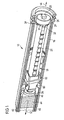
- Figure 1 shows a three-dimensional cut-away view of a first embodiment of the present disclosure.
- the drug delivery device 10 comprises a body 16 and a cartridge holder 40.
- a medicament cartridge 42 is located within the cartridge holder 40.
- the medicament cartridge 42 contains a number of doses of a fluid medicinal product.
- the cartridge holder 40 is attached to the body 16 of the drug delivery device 10.
- the assembly is located substantially within the body 16 of the drug delivery device 10.
- the second member 22 is arranged on the main axis of the drug delivery device 10 and is initially located almost entirely within the body 16.
- the second member 22 is essentially tubular in shape, having a bore that extends completely through its main axis.
- the second member 22 comprises an internal thread. At the proximal end, the second member 22 comprises a set of teeth 32.
- the first member 20 is located within the bore of the second member 22 and comprises an external thread, which engages with the internal thread at the distal end of the second member 22.
- a pad 26 is located that is disposed to abut the proximal face 46 of the cartridge bung 44, while the drug delivery device 10 is operated by a user.
- the first member 20 comprises a part at its proximal end, which has a non-circular cross section. This part of the first member 20 extends beyond the proximal end of the second member 22.
- the non-circular shaped part of the first member 20 extends through an aperture in the adjusting member 24 such that axial movement between the first member 20 and the adjustment member 24 is permitted, whilst relative rotational movement is not permitted.
- the adjustment member 24 has a set of teeth 34 on its distal face, disposed towards the teeth 32 on the proximal end of the second member 22.
- the adjustment member 24 is initially mounted on a proximal detent, which is not explicitly shown, located at the second member 22, such that opposing sets of teeth are not engaged.
- the piston rod formed by the first member 20 and the second member 22 is advanced by means of the lever 62 and carrier plate 60 to displace the cartridge bung 44 and to deliver doses of the fluid medicinal product.
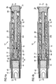
- Figure 2a shows the drug delivery device in a section view before the adjustment.
- a medicament cartridge 42 is first placed into the cartridge holder 40 and the cartridge holder 40 is then connected to the body 16.
- a gap 50 is shown between the pad 26 and the proximal face 46 of the cartridge bung 44.
- the assembly is then adjusted such that the gap 50 between the pad 26 at the extreme distal end of the first member 20 and the cartridge bung 44 is removed.
- the dose member 28 is first displaced in the distal direction 12 until it engages a stop face 19 on the fixed member 18. This step is important to ensure that all mechanism tolerances are correctly taken up and that a back off spring, which is not shown, is compressed.
- the adjustment member 24 is then rotated relative to the second member 22. This action advances the first member 20 through the internal thread of the second member 22. The first member 20 is rotated until it abuts the proximal end face 46 of the cartridge bung 44.
- a distal detent which is not explicitly shown, is located at the second member 22.
- the adjustment member 24 When the adjustment member 24 is pushed in distal direction 12, it is thereby being pushed onto the distal detent on the second member 22. This action now engages the sets of teeth between the second member 22 and the adjustment member 24, thus locking them to prevent relative rotation, thereby forming the piston rod.
- the distal detent prevents the axial disengagement of the opposing sets of teeth.
- the assembly can then be sealed by the addition of a cap, which is not shown, into the aperture at the proximal end of the dose member 28.
- This cap can be used to code the drug delivery device 10 by means of color or tactile features, to indicate the type of fluid medicinal product contained therein.
- the piston rod formed by the first member 20 and the second member 22 is advanced by means of the lever 62 and carrier plate 60 to displace the cartridge bung 44 and to deliver doses of fluid medicinal product.
- One part of the lever 62 is engaged with the fixed member 18 and another part of the lever 62 is connected to the dose member 28.
- the dose member 28 moves proximally with respect to the body 16, thereby moving the lever 62 proximally with respect to the piston rod.
- the dose member 28 For dispensing a dose of the fluid medicinal product, the dose member 28 is moved in distal direction, whereby the lever 62 and the piston rod are displaced towards the distal end of the drug delivery device. The distal movement of the piston rod displaces the cartridge bung 44 to deliver a dose of a fluid medicinal product.
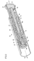
- Figure 3 shows a three-dimensional cut-away view of a second embodiment of the assembly.
- the second member 22 comprises a lead screw and the first member is split up into two parts, a distal part 201 and a proximal part 202.
- the drug delivery device comprises two parts, a body 16 and a cartridge holder 40.
- a medicament cartridge 42 is located, which contains a number of doses of fluid medicinal product.
- the cartridge holder is permanently attached to the body 16 of the drug delivery device.
- the assembly is located substantially within the body 16 of the drug delivery device.
- the second member 22 lies on the main axis of the pen-type injector and is initially located almost entirely within the body.
- the second member 22 is essentially tubular in shape with helical thread forms 23 on external surfaces and a bore 25 that extends completely through the main axis.
- the second member 22 has an internal thread 31. Adjacent to the internal thread 31 within the bore 23 of the second member 22 a set of spline features 69 is arranged circularly around the internal surface of the bore 23. Proximally behind these spline features 69, two detents are located, which are not explicitly shown.
- a first member is located within the bore 23 of the second member 22.
- the distal part 201 of the first member comprises an external thread 30, which engages with the internal thread 31 at the distal end of the second member 22.
- the first member is connected to a bearing 66 by means of a journal that allows relative rotation between the parts but not axial movement. In use, the bearing 66 is disposed to abut the proximal face of the cartridge bung.
- the distal part 201 of the first member comprises a part which has a non-circular cross section.
- This part comprising the non-circular cross section extends into a distal aperture of a proximal part 202 of the first member, such that limited relative axial movement between the two parts is permitted, whilst relative rotational movement is not.
- the proximal part 202 of the first member is initially mounted in a detent of the second member 22, which is not explicitly shown, such that the spline features 69 are not engaged with the opposing set of spline features on the second member 22.
- this detent When mounted on this detent, relative rotation between the proximal part 202 of the first member and the second member 22 is permitted.
- the adjustment member 24 is then mounted in a proximal detent 29 on the dose member 28, such that spline features 68 are not engaged with a set of opposing spline features on an internal cylindrical surface of the dose member 28.
- Figure 4a shows the drug delivery device in a section view before the adjustment similar as shown in figure 3 .
- a medicament cartridge 42 is first placed into the cartridge holder 40 and the cartridge holder 40 is then connected to the body 16. There is a gap 50 between the bearing 66 and the proximal face 46 of the cartridge bung 44. The assembly is then adjusted such that the gap 50 between the bearing 66 at the extreme distal end of the first member 201 and the cartridge bung 44 is removed.
- the assembly comprises a nut at its distal end, through which the lead screw may be screwed. It should be noted at this point that the dose member 28 and the nut 64 are fixed in rotation relative to the body 16 and the nut 64 is also fixed axially relative to the body 16. When the dose member 28 is in the position as shown in figure 4a , the relative interconnections between the components are provided such that the second member 22 is also held in fixed rotational position relative to the body 16.
- the dose member 28 is first displaced in the distal direction 12 until it engages its stop face 19 at the nut 64. Thereby, all mechanical tolerances are taken up.
- the adjustment member 24 is then rotated relative to the dose member 28. This action rotates the proximal part 202 of the first member and the distal part 201 of the first member. Thereby the distal part 201 of the first member is advanced through the thread 31 at the second member 22 until the bearing 66 contacts the cartridge bung 44.
- This abutment can be detected, for example by a strain gauge.
- the adjustment member 24 is then pushed in distal direction onto the detent 29 on the dose member 28. This action engages two sets of spline features 68 between the parts, thus locking them to prevent relative rotation.
- the distal part 201 of the first member is now locked in position relative to the second member 22.
- the first member, the second member 22 and the bearing 66 are advanced by interaction with the dose member 28 and the nut 64 to displace the cartridge bung 44 and deliver doses of a fluid medicinal product.
Description
- The present invention relates to an assembly for use in a drug delivery device.
- Drug delivery devices are generally known for the administration of a medicinal product, for example insulin or heparin, but also for other medicinal products for self-administration by a patient. Most of the drug delivery devices are pen-type injectors, which dispense a pre-set dose of a fluid medicinal product.
- Document
EP 0 058 536 A1 shows an example for a drug delivery device where a pre-set dose can be administered. For dispensing the dose, a plunger is screwed with respect to a fixed sleeve, thereby advancing a plug in a fluid containing cylinder. - Before the first use of the drug delivery device the user usually has to prime the drug delivery device. Users who are unfamiliar with such pen-type injectors may fail or incorrectly prime their drug delivery device before dispensing the first dose.
- It is an object to the present disclosure to provide an assembly for use in a drug delivery device, which helps to improve usability and ensures the accuracy of the first dispensed dose of a fluid medicinal product.
- According to a first aspect of the present disclosure, an assembly is provided, which is forming a piston rod for advancing a cartridge bung in a drug delivery device. The assembly comprises a first member and a second member. In a first state of the assembly, the first and the second member are moveable with respect to each other to adjust the length of the piston rod. In a second state of the assembly, the first member is locked in position with respect to the second member in order to define a fixed length of the piston rod. In the second state of the assembly, i. e. when the length of the piston rod is fixed, the assembly may be set-up and may be used by a patient for the application of a medicament, which may comprise setting and dispensing a dose of a medicinal product. In this state, the operation of the device may be performed only once or also repeatedly. In the first state, the assembly is used for preparative purposes only and is not suited for a set and dispense action.
- After the piston rod is formed in the second state, the drug delivery device can be used without the requirement for a priming dose to prepare the device first.
- For fixed dose devices the dose setting may include the step of loading the device whereas afterwards dispensing a predefined amount of medication is performed, whereas in the case of a variable dose device the step of setting includes the adjustment of the device to define the amount of medication to be dispensed in the subsequent dispensing operation.
- By means of the adjustment of the length of the piston rod, tolerances of the mechanical elements are removed from the assembly. Additionally, the need for a priming operation before delivering the first dose can be avoided. Thereby, one advantage is that the user will not accidentally inject prime fluid.
- This arrangement may be used for fixed dose pens as well as for variable dose pens.
- The second member may comprise ratchet teeth or a lead screw as part of the related drive mechanism. In case of a ratchet teeth based drive mechanism, the piston rod is linearly advanced and in case of a lead screw based drive mechanism, the piston rod is rotationally advanced.
- In a preferred embodiment in the first state of the assembly, the first member is coupled to an adjustment member such that relative axial movement between the first member and the adjustment member is permitted and rotational movement relative to each other is prevented.
- The first member may comprise a part, which has a non-circular cross section. The adjustment member may comprise an aperture through which the part of the first member, which has a non-circular cross section, can extend.
- The shape of the non-circular cross section of the first member and the shape of the aperture of the adjustment member match such that relative axial movement between the first member and the adjustment member is permitted and relative rotational movement is prevented.
- The assembly comprises a distal end, where the medicinal product may be dispensed out of an assembled medicament cartridge and a proximal end, which indicates the end opposite to the distal end.
- The first member may be located within a bore along the longitudinal axis of the second member and extends beyond the proximal end of the second member. The adjustment member may control the rotational movement of the first member through the second member. Additionally, the location of the first member with respect to the second member may be locked by means of the adjustment member.
- In another preferred embodiment, the assembly comprises a threaded engagement between the first member and the second member.
- The first member may comprise an external thread, which engages with an internal thread of the distal end of the second member. The adjustment member is rotatable relative to the second member. Preferably, the adjustment is intended to be undertaken during assembly of the device in the factory. Consequently, the rotation of the adjustment member may be performed by a machine. As a consequence of the rotational movement of the adjustment member, the first member is advanced through the second member.
- In a particularly preferred embodiment, the threaded engagement is self-locking.
- The pitch of the threads at the first and at the second member may be chosen such that the threaded engagement is self-locking. This means that an axial displacement can not result in a rotational movement because of the low pitch and the dynamic friction between the engaged threads. Due to the self-locking threaded engagement, it is not necessary to lock the first member with the second member at the proximal end.
- According to another preferred embodiment, the first member is at least partly arranged inside the second member.
- The first member may protrude from the distal end and from the proximal end of the second member.
- In another preferred embodiment, the adjustment member is arranged such that a rotational movement of the adjustment member relative to the second member advances the first member axially relative to the second member.
- In this case, the adjustment member is connected to the first member such that rotating the adjustment member advances the first member through the second member.
- In a particular preferred embodiment, the first member comprises a pad configured to abut an assembled cartridge bung while being advanced relative to the second member.
- At the distal end of the first member, the first member may comprise a pad that protrudes from the second member and may abut a proximal face of a cartridge bung. By advancing the piston rod, the pad applies a pressure onto the cartridge bung, thereby pushing the cartridge bung in distal direction. The movement of the cartridge bung expels a fluid medicinal product out of an assembled medicament cartridge.
- In addition, a bearing might be located at the distal end of the first member, which can abut a proximal face of a cartridge bung. The bearing might be arranged such that relative rotation between the parts is permitted but relative axial movement is not permitted.
- The bearing might be useful in the case that the piston rod rotates during the dispense of a dose of a fluid medicinal product. The rotational movement leads to a torque, which is absorbed by the bearing such that the bung is only axially displaced.
- In another particular preferred embodiment, the advancing movement of the first member relative to the second member is stopped when the pad contacts the cartridge bung.
- Before the first use of the drug delivery device, there is typically a gap between the end of the piston rod and the cartridge bung. This gap is a consequence of the tolerances associated with all the assembled parts and the requirement not to pre-load the bung axially in the assembled device. The gap is closed by the pad, which is advanced into contact with the cartridge bung through its axial motion relative to the second member.
- After closing the gap between the pad and the cartridge bung properly, the correct volume of a medicinal product may be delivered in the first dispensed dose.
- According to another particular preferred embodiment, the assembly comprises a means to detect the abutment of the pad upon the bung and to stop the movement of the first member.
- The abutment of the pad and a proximal face of the bung can be detected for example by a strain gauge to measure torque and give according feedback, which at a predetermined level indicates contact between the pad and the cartridge bung. Another possibility to detect the abutment of the pad and the cartridge bung is for example by using a clutch that is designed to slip at a certain torque value.
- In a preferred embodiment, in a second state of the assembly, the first member and the second member are suitable for moving the cartridge bung into an assembled medicament cartridge for dispensing a fluid medicinal product.
- After having connected the first member with the second member a piston rod is formed. The piston rod may be advanced by means of a drive mechanism. The advancing piston rod may move a cartridge bung in an assembled medicament cartridge. Due to the advancing cartridge bung, a fluid medicinal product is dispensed from the medicament cartridge.
- In another preferred embodiment, the adjustment member is located at the distal end of the assembly.
- In one preferred embodiment in the second state of the assembly the adjustment member is locked with the second member in order to prevent rotational and axial movement with respect to the second member.
- A set of teeth on the distal end of the adjustment member may be disposed towards another set of teeth on the proximal end of the second member. The adjustment member in the first state is, for example mounted on a proximal detent of the second member, such that the opposing sets of teeth are not engaged. In the second state, the sets of teeth between the two parts engage, thus locking them to prevent relative rotation.
- In another preferred embodiment, in the second state of the assembly, the adjustment member is connected to the first member such that relative rotation and axial displacement between the adjustment member and the first member is prevented.
- Thus, the first member and the second member are forming the piston rod due to the rigid connection.
- In a third aspect of the present disclosure, a method for assembling a drug delivery device is provided, wherein the drug delivery device comprises a body, a piston rod and a cartridge holder in which a medicament cartridge is located. The medicament cartridge comprises a bung. An adjustment member and a pad located at the distal end of the first member are moved with respect to a second member until the pad is abutting the cartridge bung of the medicament cartridge. The first member is coupled with the second member such that further movement between the first member and the second member is prevented whereby the piston rod is formed.
- An alternative method of the final assembly could be that a medicament cartridge is placed into the cartridge holder and biased in its most distal position. The position of the cartridge bung is then measured. The position of the distal end of the first member or, if applicable, the position of the bearing within the device mechanism is also measured and the required position of the first member relative to the body is calculated, such that when the two sub-assemblies are connected together, there is no gap or excessive pre-load between the end of the first member and the cartridge bung.
- The first member is adjusted relative to the second member and locked in the position defined by the calculation during assembly of the device.
- The terms "medicinal product", "fluid medicinal product" and "medicament" as used herein, preferably mean a pharmaceutical formulation containing at least one pharmaceutically active compound,
wherein in one embodiment the pharmaceutically active compound has a molecular weight up to 1500 Da and/or is a peptide, a proteine, a polysaccharide, a vaccine, a DNA, a RNA, an enzyme, an antibody, a hormone or an oligonucleotide, or a mixture of the above-mentioned pharmaceutically active compound,
wherein in a further embodiment the pharmaceutically active compound is useful for the treatment and/or prophylaxis of diabetes mellitus or complications associated with diabetes mellitus such as diabetic retinopathy, thromboembolism disorders such as deep vein or pulmonary thromboembolism, acute coronary syndrome (ACS), angina, myocardial infarction, cancer, macular degeneration, inflammation, hay fever, atherosclerosis and/or rheumatoid arthritis,
wherein in a further embodiment the pharmaceutically active compound comprises at least one peptide for the treatment and/or prophylaxis of diabetes mellitus or complications associated with diabetes mellitus such as diabetic retinopathy,
wherein in a further embodiment the pharmaceutically active compound comprises at least one human insulin or a human insulin analogue or derivative, glucagon-like peptide (GLP-1) or an analogue or derivative thereof, or exedin-3 or exedin-4 or an analogue or derivative of exedin-3 or exedin-4. - Insulin analogues are for example Gly(A21), Arg(B31), Arg(B32) human insulin; Lys(B3), Glu(B29) human insulin; Lys(B28), Pro(B29) human insulin; Asp(B28) human insulin; human insulin, wherein proline in position B28 is replaced by Asp, Lys, Leu, Val or Ala and wherein in position B29 Lys may be replaced by Pro; Ala(B26) human insulin; Des(B28-B30) human insulin; Des(B27) human insulin and Des(B30) human insulin.
- Insulin derivates are for example B29-N-myristoyl-des(B30) human insulin; B29-N-palmitoyl-des(B30) human insulin; B29-N-myristoyl human insulin; B29-N-palmitoyl human insulin; B28-N-myristoyl LysB28ProB29 human insulin; B28-N-palmitoyl-LysB28ProB29 human insulin; B30-N-myristoyl-ThrB29LysB30 human insulin; B30-N-palmitoyl- ThrB29LysB30 human insulin; B29-N-(N-palmitoyl-Y-glutamyl)-des(B30) human insulin; B29-N-(N-lithocholyl-Y-glutamyl)-des(B30) human insulin; B29-N-(ω-carboxyheptadecanoyl)-des(B30) human insulin and B29-N-(ω-carboxyheptadecanoyl) human insulin.
- Exendin-4 for example means Exendin-4(1-39), a peptide of the sequence H-His-Gly-Glu-Gly-Thr-Phe-Thr-Ser-Asp-Leu-Ser-Lys-Gln-Met-Glu-Glu-Glu-Ala-Val-Arg-Leu-Phe-Ile-Glu-Trp-Leu-Lys-Asn-Gly-Gly-Pro-Ser-Ser-Gly-Ala-Pro-Pro-Pro-Ser-NH2.
- Exendin-4 derivatives are for example selected from the following list of compounds:
- H-(Lys)4-des Pro36, des Pro37 Exendin-4(1-39)-NH2,
- H-(Lys)5-des Pro36, des Pro37 Exendin-4(1-39)-NH2,
- des Pro36 [Asp28] Exendin-4(1-39),
- des Pro36 [IsoAsp28] Exendin-4(1-39),
- des Pro36 [Met(O)14, Asp28] Exendin-4(1-39),
- des Pro36 [Met(O)14, IsoAsp28] Exendin-4(1-39),
- des Pro36 [Trp(02)25, Asp28] Exendin-4(1-39),
- des Pro36 [Trp(02)25, IsoAsp28] Exendin-4(1-39),
- des Pro36 [Met(O)14 Trp(02)25, Asp28] Exendin-4(1-39),
- des Pro36 [Met(O)14 Trp(O2)25, IsoAsp28] Exendin-4(1-39); or
- des Pro36 [Asp28] Exendin-4(1-39),
- des Pro36 [IsoAsp28] Exendin-4(1-39),
- des Pro36 [Met(O)14, Asp28] Exendin-4(1-39),
- des Pro36 [Met(O)14, IsoAsp28] Exendin-4(1-39),
- des Pro36 [Trp(02)25, Asp28] Exendin-4(1-39),
- des Pro36 [Trp(O2)25, IsoAsp28] Exendin-4(1-39),
- des Pro36 [Met(O)14 Trp(O2)25, Asp28] Exendin-4(1-39),
- des Pro36 [Met(O)14 Trp(O2)25, IsoAsp28] Exendin-4(1-39),
- wherein the group -Lys6-NH2 may be bound to the C-terminus of the Exendin-4 derivative;
- or an Exendin-4 derivative of the sequence
- H-(Lys)6-des Pro36 [Asp28] Exendin-4(1-39)-Lys6-NH2,
- des Asp28 Pro36, Pro37, Pro38Exendin-4(1-39)-NH2,
- H-(Lys)6-des Pro36, Pro38 [Asp28] Exendin-4(1-39)-NH2,
- H-Asn-(Glu)5des Pro36, Pro37, Pro38 [Asp28] Exendin-4(1-39)-NH2,
- des Pro36, Pro37, Pro38 [Asp28] Exendin-4(1-39)-(Lys)6-NH2,
- H-(Lys)6-des Pro36, Pro37, Pro38 [Asp28] Exendin-4(1-39)-(Lys)6-NH2,
- H-Asn-(Glu)5-des Pro36, Pro37, Pro38 [Asp28] Exendin-4(1-39)-(Lys)6-NH2,
- H-(Lys)6-des Pro36 [Trp(02)25, Asp28] Exendin-4(1-39)-Lys6-NH2,
- H-des Asp28 Pro36, Pro37, Pro38 [Trp(02)25] Exendin-4(1-39)-NH2,
- H-(Lys)6-des Pro36, Pro37, Pro38 [Trp(02)25, Asp28] Exendin-4(1-39)-NH2,
- H-Asn-(Glu)5-des Pro36, Pro37, Pro38 [Trp(02)25, Asp28] Exendin-4(1-39)-NH2,
- des Pro36, Pro37, Pro38 [Trp(02)25, Asp28] Exendin-4(1-39)-(Lys)6-NH2,
- H-(Lys)6-des Pro36, Pro37, Pro38 [Trp(O2)25, Asp28] Exendin-4(1-39)-(Lys)6-NH2,
- H-Asn-(Glu)5-des Pro36, Pro37, Pro38 [Trp(02)25, Asp28] Exendin-4(1-39)-(Lys)6-NH2,
- H-(Lys)6-des Pro36 [Met(O)14, Asp28] Exendin-4(1-39)-Lys6-NH2,
- des Met(O)14 Asp28 Pro36, Pro37, Pro38 Exendin-4(1-39)-NH2,
- H-(Lys)6-desPro36, Pro37, Pro38 [Met(O)14, Asp28] Exendin-4(1-39)-NH2,
- H-Asn-(Glu)5-des Pro36, Pro37, Pro38 [Met(O)14, Asp28] Exendin-4(1-39)-NH2,
- des Pro36, Pro37, Pro38 [Met(O)14, Asp28] Exendin-4(1-39)-(Lys)6-NH2,
- H-(Lys)6-des Pro36, Pro37, Pro38 [Met(O)14, Asp28] Exendin-4(1-39)-(Lys)6-NH2,
- H-Asn-(Glu)5 des Pro36, Pro37, Pro38 [Met(O)14, Asp28] Exendin-4(1-39)-(Lys)6-NH2,
- H-Lys6-des Pro36 [Met(O)14, Trp(02)25, Asp28] Exendin-4(1-39)-Lys6-NH2,
- H-des Asp28 Pro36, Pro37, Pro38 [Met(O)14, Trp(O2)25] Exendin-4(1-39)-NH2,
- H-(Lys)6-des Pro36, Pro37, Pro38 [Met(O)14, Asp28] Exendin-4(1-39)-NH2,
- H-Asn-(Glu)5-des Pro36, Pro37, Pro38 [Met(O)14, Trp(02)25, Asp28] Exendin-4(1-39)-NH2,
- des Pro36, Pro37, Pro38 [Met(O)14, Trp(O2)25, Asp28] Exendin-4(1-39)-(Lys)6-NH2,
- H-(Lys)6-des Pro36, Pro37, Pro38 [Met(O)14, Trp(O2)25, Asp28] Exendin-4(S1-39)-(Lys)6-NH2,
- H-Asn-(Glu)5-des Pro36, Pro37, Pro38 [Met(O)14, Trp(02)25, Asp28] Exendin-4(1-39)-(Lys)6-NH2;
- or a pharmaceutically acceptable salt or solvate of any one of the afore-mentioned Exedin-4 derivative.
- Hormones are for example hypophysis hormones or hypothalamus hormones or regulatory active peptides and their antagonists as listed in Rote Liste, ed. 2008, (Follitropin, Lutropin, Choriongonadotropin, Menotropin), Somatropine (Somatropin), Desmopressin, Terlipressin, Gonadorelin, Triptorelin, Leuprorelin, Buserelin, Nafarelin, Goserelin.
- A polysaccharide is for example a glucosaminoglycane, a hyaluronic acid, a heparin, a low molecular weight heparin or an ultra low molecular weight heparin or a derivative thereof, or a sulphated, e.g. a poly-sulphated form of the above-mentioned polysaccharides, and/or a pharmaceutically acceptable salt thereof. An example of a pharmaceutically acceptable salt of a poly-sulphated low molecular weight heparin is enoxaparin sodium.
- Pharmaceutically acceptable salts are for example acid addition salts and basic salts. Acid addition salts are e.g. HCl or HBr salts. Basic salts are e.g. salts having a cation selected from alkali or alkaline, e.g. Na+, or K+, or Ca2+, or an ammonium ion N+(R1)(R2)(R3)(R4), wherein R1 to R4 independently of each other mean: hydrogen, an optionally substituted C1-C6-alkyl group, an optionally substituted C2-C6-alkenyl group, an optionally substituted C6-C10-aryl group, or an optionally substituted C6-C10-heteroaryl group. Further examples of pharmaceutically acceptable salts are described in "Remington's Pharmaceutical Sciences" 17. ed. Alfonso R. Gennaro (Ed.), Mark Publishing Company, Easton, Pa., U.S.A., 1985 and in Encyclopedia of Pharmaceutical Technology.
- Pharmaceutically acceptable solvates are for example hydrates.
- In the following, the disclosed devices and methods are described in further details with reference to the drawings, wherein
- Figure 1
- shows a cut-away view of a drug delivery device comprising a second member, wherein the second member comprises ratchet teeth,
- Figure 2a
- shows a section view before adjusting the drug delivery device, wherein the drug delivery device comprises a second member and the second member comprises ratchet teeth,
- Figure 2b
- shows a section view after adjusting the drug delivery device, wherein the drug delivery device comprises a second member and the second member comprises ratchet teeth,
- Figure 3
- shows a cut-away view of a drug delivery device comprising a second member, wherein the second member comprises a lead screw,
- Figure 4a
- shows a section view before adjusting the drug delivery device, wherein the drug delivery device comprises a second member and the second member comprises a lead screw, and
- Figure 4b
- shows a section view after adjusting the drug delivery device, wherein the drug delivery device comprises a second member and the second member comprises a lead screw.
- Some preferred embodiments of the arrangement according to the present disclosure will now be discussed with reference to
figure 1 ,figures 2a and 2b ,figure 3 andfigures 4a and 4b . Identical reference signs denote identical or comparable components. -
Figure 1 shows a three-dimensional cut-away view of a first embodiment of the present disclosure. - The
drug delivery device 10 comprises abody 16 and acartridge holder 40. Amedicament cartridge 42 is located within thecartridge holder 40. Themedicament cartridge 42 contains a number of doses of a fluid medicinal product. During use, thecartridge holder 40 is attached to thebody 16 of thedrug delivery device 10. - The assembly is located substantially within the
body 16 of thedrug delivery device 10. Thesecond member 22 is arranged on the main axis of thedrug delivery device 10 and is initially located almost entirely within thebody 16. Thesecond member 22 is essentially tubular in shape, having a bore that extends completely through its main axis. - At the distal end of the bore, the
second member 22 comprises an internal thread. At the proximal end, thesecond member 22 comprises a set ofteeth 32. - The
first member 20 is located within the bore of thesecond member 22 and comprises an external thread, which engages with the internal thread at the distal end of thesecond member 22. At the extreme distal end of the first member 20 apad 26 is located that is disposed to abut theproximal face 46 of thecartridge bung 44, while thedrug delivery device 10 is operated by a user. - At the proximal end, the
first member 20 comprises a part at its proximal end, which has a non-circular cross section. This part of thefirst member 20 extends beyond the proximal end of thesecond member 22. The non-circular shaped part of thefirst member 20 extends through an aperture in the adjustingmember 24 such that axial movement between thefirst member 20 and theadjustment member 24 is permitted, whilst relative rotational movement is not permitted. - The
adjustment member 24 has a set ofteeth 34 on its distal face, disposed towards theteeth 32 on the proximal end of thesecond member 22. Theadjustment member 24 is initially mounted on a proximal detent, which is not explicitly shown, located at thesecond member 22, such that opposing sets of teeth are not engaged. - When mounted on this detent, relative rotation between the
adjustment member 24 and thesecond member 22 is permitted but accidental engagement between the opposing sets of teeth is prevented. - During use, the piston rod formed by the
first member 20 and thesecond member 22 is advanced by means of thelever 62 andcarrier plate 60 to displace thecartridge bung 44 and to deliver doses of the fluid medicinal product. -
Figure 2a shows the drug delivery device in a section view before the adjustment. - During the final assembly, a
medicament cartridge 42 is first placed into thecartridge holder 40 and thecartridge holder 40 is then connected to thebody 16. Agap 50 is shown between thepad 26 and theproximal face 46 of thecartridge bung 44. The assembly is then adjusted such that thegap 50 between thepad 26 at the extreme distal end of thefirst member 20 and thecartridge bung 44 is removed. - The
dose member 28 is first displaced in thedistal direction 12 until it engages astop face 19 on the fixedmember 18. This step is important to ensure that all mechanism tolerances are correctly taken up and that a back off spring, which is not shown, is compressed. - The
adjustment member 24 is then rotated relative to thesecond member 22. This action advances thefirst member 20 through the internal thread of thesecond member 22. Thefirst member 20 is rotated until it abuts theproximal end face 46 of thecartridge bung 44. - A distal detent, which is not explicitly shown, is located at the
second member 22. When theadjustment member 24 is pushed indistal direction 12, it is thereby being pushed onto the distal detent on thesecond member 22. This action now engages the sets of teeth between thesecond member 22 and theadjustment member 24, thus locking them to prevent relative rotation, thereby forming the piston rod. The distal detent prevents the axial disengagement of the opposing sets of teeth. - Since the aperture of the
adjustment member 24 remains engaged with the non-circular cross section of thefirst member 20, thefirst member 20 is now locked in position relative to thesecond member 22. This is shown infigure 2b . - The assembly can then be sealed by the addition of a cap, which is not shown, into the aperture at the proximal end of the
dose member 28. This cap can be used to code thedrug delivery device 10 by means of color or tactile features, to indicate the type of fluid medicinal product contained therein. - During use, the piston rod formed by the
first member 20 and thesecond member 22 is advanced by means of thelever 62 andcarrier plate 60 to displace thecartridge bung 44 and to deliver doses of fluid medicinal product. - One part of the
lever 62 is engaged with the fixedmember 18 and another part of thelever 62 is connected to thedose member 28. For setting a dose of the fluid medicinal product, thedose member 28 moves proximally with respect to thebody 16, thereby moving thelever 62 proximally with respect to the piston rod. - For dispensing a dose of the fluid medicinal product, the
dose member 28 is moved in distal direction, whereby thelever 62 and the piston rod are displaced towards the distal end of the drug delivery device. The distal movement of the piston rod displaces thecartridge bung 44 to deliver a dose of a fluid medicinal product. -
Figure 3 shows a three-dimensional cut-away view of a second embodiment of the assembly. In this embodiment, thesecond member 22 comprises a lead screw and the first member is split up into two parts, adistal part 201 and aproximal part 202. - Similar to
figure 1 , the drug delivery device comprises two parts, abody 16 and acartridge holder 40. Within the cartridge holder, amedicament cartridge 42 is located, which contains a number of doses of fluid medicinal product. During use, the cartridge holder is permanently attached to thebody 16 of the drug delivery device. - The assembly is located substantially within the
body 16 of the drug delivery device. Thesecond member 22 lies on the main axis of the pen-type injector and is initially located almost entirely within the body. Thesecond member 22 is essentially tubular in shape with helical thread forms 23 on external surfaces and abore 25 that extends completely through the main axis. - At the distal end of the
bore 23, thesecond member 22 has aninternal thread 31. Adjacent to theinternal thread 31 within thebore 23 of the second member 22 a set of spline features 69 is arranged circularly around the internal surface of thebore 23. Proximally behind these spline features 69, two detents are located, which are not explicitly shown. - A first member is located within the
bore 23 of thesecond member 22. Thedistal part 201 of the first member comprises anexternal thread 30, which engages with theinternal thread 31 at the distal end of thesecond member 22. At the extremedistal end 201 of the first member, the first member is connected to abearing 66 by means of a journal that allows relative rotation between the parts but not axial movement. In use, thebearing 66 is disposed to abut the proximal face of the cartridge bung. - At its proximal end, the
distal part 201 of the first member comprises a part which has a non-circular cross section. This part comprising the non-circular cross section extends into a distal aperture of aproximal part 202 of the first member, such that limited relative axial movement between the two parts is permitted, whilst relative rotational movement is not. - The
proximal part 202 of the first member is initially mounted in a detent of thesecond member 22, which is not explicitly shown, such that the spline features 69 are not engaged with the opposing set of spline features on thesecond member 22. When mounted on this detent, relative rotation between theproximal part 202 of the first member and thesecond member 22 is permitted. - The
adjustment member 24 is then mounted in aproximal detent 29 on thedose member 28, such that spline features 68 are not engaged with a set of opposing spline features on an internal cylindrical surface of thedose member 28. -
Figure 4a shows the drug delivery device in a section view before the adjustment similar as shown infigure 3 . - During final assembly, a
medicament cartridge 42 is first placed into thecartridge holder 40 and thecartridge holder 40 is then connected to thebody 16. There is agap 50 between the bearing 66 and theproximal face 46 of thecartridge bung 44. The assembly is then adjusted such that thegap 50 between the bearing 66 at the extreme distal end of thefirst member 201 and thecartridge bung 44 is removed. - The assembly comprises a nut at its distal end, through which the lead screw may be screwed. It should be noted at this point that the
dose member 28 and thenut 64 are fixed in rotation relative to thebody 16 and thenut 64 is also fixed axially relative to thebody 16. When thedose member 28 is in the position as shown infigure 4a , the relative interconnections between the components are provided such that thesecond member 22 is also held in fixed rotational position relative to thebody 16. - The
dose member 28 is first displaced in thedistal direction 12 until it engages itsstop face 19 at thenut 64. Thereby, all mechanical tolerances are taken up. Theadjustment member 24 is then rotated relative to thedose member 28. This action rotates theproximal part 202 of the first member and thedistal part 201 of the first member. Thereby thedistal part 201 of the first member is advanced through thethread 31 at thesecond member 22 until the bearing 66 contacts thecartridge bung 44. - This abutment can be detected, for example by a strain gauge. The
adjustment member 24 is then pushed in distal direction onto thedetent 29 on thedose member 28. This action engages two sets of spline features 68 between the parts, thus locking them to prevent relative rotation. - When the
adjustment member 24 is pushed indistal direction 12, this in turn displaces theproximal part 202 of the first member, engaging it onto a detent on thesecond member 22, which is not explicitly shown. This secondary action engages the two sets ofspline 69 features between theproximal part 201 of the first member and thesecond member 22, thus locking them to prevent relative rotation. This state is shown infigure 4b . - Because the aperture of the
proximal part 202 of the first member remains engaged with the part comprising the non-circular cross section on thedistal part 201 of the first member, thedistal part 201 of the first member is now locked in position relative to thesecond member 22. During use, the first member, thesecond member 22 and thebearing 66 are advanced by interaction with thedose member 28 and thenut 64 to displace thecartridge bung 44 and deliver doses of a fluid medicinal product. - The present examples and embodiments are to be considered as illustrative and not restrictive, and the invention is not to be limited to the details given herein, but may be modified within the scope and equivalence of the appended claims.
-
- 10
- drug delivery device
- 12
- distal direction
- 14
- proximal direction
- 16
- body
- 18
- fixed member
- 19
- stop face
- 20
- first member
- 201
- distal part of the first member
- 202
- proximal part of the first member
- 22
- second member
- 23
- helical thread
- 24
- adjustment member
- 25
- bore
- 26
- pad
- 28
- dose member
- 29
- proximal detent
- 30
- external thread
- 31
- internal thread
- 32
- teeth at the second member
- 34
- teeth at the adjustment member
- 40
- cartridge holder
- 42
- medicament cartridge
- 44
- cartridge bung
- 46
- proximal face of the cartridge bung
- 50
- gap
- 60
- carrier plate
- 62
- lever
- 64
- nut
- 66
- bearing
- 68
- spline features
- 69
- spline features
- 70
- opposing set of spline features
Claims (14)
- An assembly forming a piston rod (20,22) for advancing a cartridge bung (44) in a drug delivery device (10), the assembly comprising a first member (20) and a second member (22) wherein in a first state, the first (20) and the second member (22) are moveable with respect to each other to adjust the length of the piston rod and characterised in that in a second state the first member (20) is locked in position with respect to
the second member (22) in order to define a fixed length of the piston rod, wherein in the second state of the assembly a dose of a fluid medicinal product can be set and dispensed. - An assembly according to claim 1, wherein in the first state the first member (20) is coupled to an adjustment member (24) such that relative axial movement between the first member (20) and the adjustment member (24) is permitted and rotational movement relative to each other is prevented.
- An assembly according to claim 1 or 2, wherein the assembly comprises a threaded engagement between the first member (20) and the second member (22).
- An assembly according to claim 3, wherein the threaded engagement is self-locking.
- An assembly according to anyone of the previous claims, wherein the first member (20) is at least partly arranged inside the second member (22).
- An assembly according to claim 2 to 5, wherein the adjustment member (24) is arranged such that a rotational movement of the adjustment member (24) relative to the second member (22) advances the first member (20) relative to the second member (22).
- An assembly according to claim 6, wherein the first member (20) comprises a pad (26) configured to abut an assembled cartridge bung (44) while being advanced relative to the second member (22).
- An assembly according to claim 7, wherein the assembly comprises a means to detect the abutment of the pad (26) upon the bung (44) and to stop the movement of the first member (20).
- An assembly according to anyone of the previous claims, wherein in the second state of the assembly the first member (20) and the second member (22) are suitable for moving the cartridge bung (44) into an assembled cartridge (42) for dispensing a fluid medicinal product.
- An assembly according to claim 2 to 9, wherein the adjustment member (24) is located at a proximal end of the assembly.
- An assembly according to claim 2 to 10, wherein in the second state of the assembly the adjustment member (24) is locked with the second member (22) in order to prevent rotational and axial movement with respect to the second member (22).
- An assembly according to claim 2 to 10, wherein in the second state of the assembly the adjustment member (24) is connected to the first member (20) such that relative rotation and axial displacement between the adjustment member (24) and the first member (20) is prevented.
- A method for assembling a drug delivery device (10) which comprises a body (16), a piston rod and a cartridge holder (40) in which a medicament cartridge (42) is located and wherein the medicament cartridge (42) comprises a cartridge bung (44), the method comprising: moving of an adjustment member (24) to move a pad (26) located at a distal end of a first member (20) with respect to a second member (22) until the pad (26) is abutting the cartridge bung (44) of the medicament cartridge (42) and further characterised by coupling the first member (20) with the second member (22) such that movement between the first member (20) and the second member (22) is prevented whereby the piston rod is formed.
- The method according to claim 13 wherein the advancing movement of the first member (20) is stopped when the pad (26) abuts the cartridge bung (44).
Priority Applications (2)
| Application Number | Priority Date | Filing Date | Title |
|---|---|---|---|
| EP13185061.2A EP2676692A1 (en) | 2009-09-30 | 2010-09-29 | A mechanism for a drug delivery device |
| EP10766248.8A EP2482881B1 (en) | 2009-09-30 | 2010-09-29 | A mechanism for a drug delivery device |
Applications Claiming Priority (3)
| Application Number | Priority Date | Filing Date | Title |
|---|---|---|---|
| EP09171747 | 2009-09-30 | ||
| PCT/EP2010/064406 WO2011039215A1 (en) | 2009-09-30 | 2010-09-29 | A mechanism for a drug delivery device |
| EP10766248.8A EP2482881B1 (en) | 2009-09-30 | 2010-09-29 | A mechanism for a drug delivery device |
Related Child Applications (1)
| Application Number | Title | Priority Date | Filing Date |
|---|---|---|---|
| EP13185061.2 Division-Into | 2013-09-18 |
Publications (2)
| Publication Number | Publication Date |
|---|---|
| EP2482881A1 EP2482881A1 (en) | 2012-08-08 |
| EP2482881B1 true EP2482881B1 (en) | 2013-10-23 |
Family
ID=41683583
Family Applications (2)
| Application Number | Title | Priority Date | Filing Date |
|---|---|---|---|
| EP13185061.2A Withdrawn EP2676692A1 (en) | 2009-09-30 | 2010-09-29 | A mechanism for a drug delivery device |
| EP10766248.8A Active EP2482881B1 (en) | 2009-09-30 | 2010-09-29 | A mechanism for a drug delivery device |
Family Applications Before (1)
| Application Number | Title | Priority Date | Filing Date |
|---|---|---|---|
| EP13185061.2A Withdrawn EP2676692A1 (en) | 2009-09-30 | 2010-09-29 | A mechanism for a drug delivery device |
Country Status (6)
| Country | Link |
|---|---|
| US (1) | US9750890B2 (en) |
| EP (2) | EP2676692A1 (en) |
| JP (1) | JP5901526B2 (en) |
| CA (1) | CA2774608A1 (en) |
| DK (1) | DK2482881T3 (en) |
| WO (1) | WO2011039215A1 (en) |
Families Citing this family (14)
| Publication number | Priority date | Publication date | Assignee | Title |
|---|---|---|---|---|
| US8936578B2 (en) | 2008-09-18 | 2015-01-20 | Becton, Dickinson And Company | Medical injector with ratcheting plunger |
| EP2493531B2 (en) | 2009-10-30 | 2023-02-08 | Sanofi-Aventis Deutschland GmbH | Drug delivery devices and method of assembly |
| CN102686258B (en) * | 2009-11-06 | 2014-02-19 | Shl集团有限责任公司 | Medicament delivery device |
| JP5866385B2 (en) * | 2011-03-17 | 2016-02-17 | ベクトン・ディキンソン・アンド・カンパニーBecton, Dickinson And Company | Medical injector with rotatable ratchet plunger |
| TR201808673T4 (en) | 2012-05-30 | 2018-07-23 | Sanofi Aventis Deutschland | The drive mechanism and the drug delivery device for a drug delivery device. |
| US9227019B2 (en) * | 2012-08-29 | 2016-01-05 | Amgen Inc. | Pre-filled syringe identification tag |
| EP2934753B1 (en) * | 2012-12-18 | 2022-05-04 | BALDA Medical GmbH | Dosing pipette |
| DK2968777T3 (en) * | 2013-03-13 | 2019-07-29 | Sanofi Aventis Deutschland | DRIVE MECHANISM FOR A PHARMACEUTICAL ADMINISTRATION DEVICE |
| WO2015024873A1 (en) * | 2013-08-22 | 2015-02-26 | Sanofi-Aventis Deutschland Gmbh | Assembly for a drug delivery device and a method for assembling a drug delivery device |
| WO2015024874A1 (en) * | 2013-08-22 | 2015-02-26 | Sanofi-Aventis Deutschland Gmbh | Drive mechanism for a drug delivery device and a method for assembling a drug delivery device |
| US10675418B2 (en) * | 2015-07-08 | 2020-06-09 | Sanofi | Drug delivery device with load indicator |
| US20210283340A1 (en) * | 2016-07-08 | 2021-09-16 | Novo Nordisk A/S | Drug delivery device comprising an adjustment member |
| BR112019005533A2 (en) | 2016-09-29 | 2019-06-18 | Ascendis Pharma Bone Diseases As | dosing regimen for a controlled release pth compound |
| EP3758776A1 (en) | 2018-03-01 | 2021-01-06 | Sanofi | Injection device with dose size adjuster |
Family Cites Families (11)
| Publication number | Priority date | Publication date | Assignee | Title |
|---|---|---|---|---|
| US1997129A (en) * | 1933-10-27 | 1935-04-09 | Alfred C Taylor | Lubricating device |
| GB2109690B (en) * | 1981-02-12 | 1985-02-20 | Robert Charles Turner | Dose metering plunger devices for use with syringes |
| US4973318A (en) * | 1988-02-10 | 1990-11-27 | D.C.P. Af 1988 A/S | Disposable syringe |
| EP0762904B1 (en) | 1994-05-30 | 2002-10-02 | B D Medico S.à.r.l. | Injection device |
| WO2003099357A1 (en) * | 2002-05-24 | 2003-12-04 | Eli Lilly And Company | Medication injecting apparatus with fluid container piston-engaging drive member having internal hollow for accommodating drive member shifting mechanism |
| US9486581B2 (en) * | 2002-09-11 | 2016-11-08 | Becton, Dickinson And Company | Injector device with force lock-out and injection rate limiting mechanisms |
| US7699816B2 (en) * | 2002-10-15 | 2010-04-20 | Tecpharma Licensing Ag | Injection device with priming stroke |
| DE20317377U1 (en) | 2003-11-03 | 2005-03-17 | B D Medico S A R L | injection device |
| WO2007017051A1 (en) | 2005-07-25 | 2007-02-15 | Novo Nordisk A/S | A syringe device and a method of assembling the same |
| DE102006004563A1 (en) * | 2006-01-17 | 2007-07-19 | Tecpharma Licensing Ag | Injection device for administering medication has a casing, a delivery element moving in relation to the casing and a locking element |
| US7976510B2 (en) | 2008-02-28 | 2011-07-12 | Becton, Dickinson And Company | Syringe with adjustable two piece plunger rod |
-
2010
- 2010-09-29 US US13/496,537 patent/US9750890B2/en active Active
- 2010-09-29 EP EP13185061.2A patent/EP2676692A1/en not_active Withdrawn
- 2010-09-29 EP EP10766248.8A patent/EP2482881B1/en active Active
- 2010-09-29 JP JP2012531383A patent/JP5901526B2/en active Active
- 2010-09-29 CA CA2774608A patent/CA2774608A1/en not_active Abandoned
- 2010-09-29 DK DK10766248.8T patent/DK2482881T3/en active
- 2010-09-29 WO PCT/EP2010/064406 patent/WO2011039215A1/en active Application Filing
Also Published As
| Publication number | Publication date |
|---|---|
| JP2013506453A (en) | 2013-02-28 |
| DK2482881T3 (en) | 2014-01-27 |
| US9750890B2 (en) | 2017-09-05 |
| US20120283657A1 (en) | 2012-11-08 |
| EP2676692A1 (en) | 2013-12-25 |
| CA2774608A1 (en) | 2011-04-07 |
| JP5901526B2 (en) | 2016-04-13 |
| EP2482881A1 (en) | 2012-08-08 |
| WO2011039215A1 (en) | 2011-04-07 |
Similar Documents
| Publication | Publication Date | Title |
|---|---|---|
| EP2482881B1 (en) | A mechanism for a drug delivery device | |
| EP2512563B1 (en) | Dose setting mechanism with maximum dose limiting element | |
| EP2552519B1 (en) | Piston rod assembly for a drug delivery device | |
| EP2482899B1 (en) | Assembly for a drug delivery device | |
| AU2010311456B2 (en) | Drug delivery devices and method of assembly | |
| EP2414007B1 (en) | Drug delivery device | |
| US9486587B2 (en) | Assembly for a drug delivery device and drug delivery device | |
| EP2475410B1 (en) | Drive mechanism for a medication delivery device and medication delivery device | |
| AU2010255816B2 (en) | Spindle and bearing combination and drug delivery device | |
| EP2482891A1 (en) | Resettable drive assembly and drug delivery device | |
| WO2010139645A1 (en) | Dose setting mechanism for a drug delivery device | |
| DK2579928T3 (en) | DRIVE DEVICE, DRIVE COMPONENT AND DEVICE FOR PHARMACEUTICAL DISPENSER | |
| CA2811953C (en) | Drive mechanism for a drug delivery device and drug delivery device |
Legal Events
| Date | Code | Title | Description |
|---|---|---|---|
| PUAI | Public reference made under article 153(3) epc to a published international application that has entered the european phase |
Free format text: ORIGINAL CODE: 0009012 |
|
| 17P | Request for examination filed |
Effective date: 20120502 |
|
| AK | Designated contracting states |
Kind code of ref document: A1 Designated state(s): AL AT BE BG CH CY CZ DE DK EE ES FI FR GB GR HR HU IE IS IT LI LT LU LV MC MK MT NL NO PL PT RO SE SI SK SM TR |
|
| DAX | Request for extension of the european patent (deleted) | ||
| GRAP | Despatch of communication of intention to grant a patent |
Free format text: ORIGINAL CODE: EPIDOSNIGR1 |
|
| INTG | Intention to grant announced |
Effective date: 20130515 |
|
| GRAS | Grant fee paid |
Free format text: ORIGINAL CODE: EPIDOSNIGR3 |
|
| GRAA | (expected) grant |
Free format text: ORIGINAL CODE: 0009210 |
|
| AK | Designated contracting states |
Kind code of ref document: B1 Designated state(s): AL AT BE BG CH CY CZ DE DK EE ES FI FR GB GR HR HU IE IS IT LI LT LU LV MC MK MT NL NO PL PT RO SE SI SK SM TR |
|
| REG | Reference to a national code |
Ref country code: GB Ref legal event code: FG4D |
|
| REG | Reference to a national code |
Ref country code: CH Ref legal event code: EP |
|
| REG | Reference to a national code |
Ref country code: AT Ref legal event code: REF Ref document number: 637203 Country of ref document: AT Kind code of ref document: T Effective date: 20131115 |
|
| REG | Reference to a national code |
Ref country code: IE Ref legal event code: FG4D |
|
| REG | Reference to a national code |
Ref country code: DE Ref legal event code: R096 Ref document number: 602010011222 Country of ref document: DE Effective date: 20131224 |
|
| REG | Reference to a national code |
Ref country code: DK Ref legal event code: T3 Effective date: 20140126 |
|
| REG | Reference to a national code |
Ref country code: NL Ref legal event code: VDEP Effective date: 20131023 |
|
| REG | Reference to a national code |
Ref country code: AT Ref legal event code: MK05 Ref document number: 637203 Country of ref document: AT Kind code of ref document: T Effective date: 20131023 |
|
| REG | Reference to a national code |
Ref country code: LT Ref legal event code: MG4D |
|
| PG25 | Lapsed in a contracting state [announced via postgrant information from national office to epo] |
Ref country code: NL Free format text: LAPSE BECAUSE OF FAILURE TO SUBMIT A TRANSLATION OF THE DESCRIPTION OR TO PAY THE FEE WITHIN THE PRESCRIBED TIME-LIMIT Effective date: 20131023 Ref country code: HR Free format text: LAPSE BECAUSE OF FAILURE TO SUBMIT A TRANSLATION OF THE DESCRIPTION OR TO PAY THE FEE WITHIN THE PRESCRIBED TIME-LIMIT Effective date: 20131023 Ref country code: IS Free format text: LAPSE BECAUSE OF FAILURE TO SUBMIT A TRANSLATION OF THE DESCRIPTION OR TO PAY THE FEE WITHIN THE PRESCRIBED TIME-LIMIT Effective date: 20140223 Ref country code: NO Free format text: LAPSE BECAUSE OF FAILURE TO SUBMIT A TRANSLATION OF THE DESCRIPTION OR TO PAY THE FEE WITHIN THE PRESCRIBED TIME-LIMIT Effective date: 20140123 Ref country code: BE Free format text: LAPSE BECAUSE OF FAILURE TO SUBMIT A TRANSLATION OF THE DESCRIPTION OR TO PAY THE FEE WITHIN THE PRESCRIBED TIME-LIMIT Effective date: 20131023 Ref country code: FI Free format text: LAPSE BECAUSE OF FAILURE TO SUBMIT A TRANSLATION OF THE DESCRIPTION OR TO PAY THE FEE WITHIN THE PRESCRIBED TIME-LIMIT Effective date: 20131023 Ref country code: LT Free format text: LAPSE BECAUSE OF FAILURE TO SUBMIT A TRANSLATION OF THE DESCRIPTION OR TO PAY THE FEE WITHIN THE PRESCRIBED TIME-LIMIT Effective date: 20131023 Ref country code: SE Free format text: LAPSE BECAUSE OF FAILURE TO SUBMIT A TRANSLATION OF THE DESCRIPTION OR TO PAY THE FEE WITHIN THE PRESCRIBED TIME-LIMIT Effective date: 20131023 |
|
| PG25 | Lapsed in a contracting state [announced via postgrant information from national office to epo] |
Ref country code: ES Free format text: LAPSE BECAUSE OF FAILURE TO SUBMIT A TRANSLATION OF THE DESCRIPTION OR TO PAY THE FEE WITHIN THE PRESCRIBED TIME-LIMIT Effective date: 20131023 Ref country code: AT Free format text: LAPSE BECAUSE OF FAILURE TO SUBMIT A TRANSLATION OF THE DESCRIPTION OR TO PAY THE FEE WITHIN THE PRESCRIBED TIME-LIMIT Effective date: 20131023 Ref country code: CY Free format text: LAPSE BECAUSE OF FAILURE TO SUBMIT A TRANSLATION OF THE DESCRIPTION OR TO PAY THE FEE WITHIN THE PRESCRIBED TIME-LIMIT Effective date: 20131023 Ref country code: LV Free format text: LAPSE BECAUSE OF FAILURE TO SUBMIT A TRANSLATION OF THE DESCRIPTION OR TO PAY THE FEE WITHIN THE PRESCRIBED TIME-LIMIT Effective date: 20131023 |
|
| PG25 | Lapsed in a contracting state [announced via postgrant information from national office to epo] |
Ref country code: PT Free format text: LAPSE BECAUSE OF FAILURE TO SUBMIT A TRANSLATION OF THE DESCRIPTION OR TO PAY THE FEE WITHIN THE PRESCRIBED TIME-LIMIT Effective date: 20140224 |
|
| REG | Reference to a national code |
Ref country code: DE Ref legal event code: R097 Ref document number: 602010011222 Country of ref document: DE |
|
| PG25 | Lapsed in a contracting state [announced via postgrant information from national office to epo] |
Ref country code: EE Free format text: LAPSE BECAUSE OF FAILURE TO SUBMIT A TRANSLATION OF THE DESCRIPTION OR TO PAY THE FEE WITHIN THE PRESCRIBED TIME-LIMIT Effective date: 20131023 |
|
| PG25 | Lapsed in a contracting state [announced via postgrant information from national office to epo] |
Ref country code: CZ Free format text: LAPSE BECAUSE OF FAILURE TO SUBMIT A TRANSLATION OF THE DESCRIPTION OR TO PAY THE FEE WITHIN THE PRESCRIBED TIME-LIMIT Effective date: 20131023 Ref country code: SK Free format text: LAPSE BECAUSE OF FAILURE TO SUBMIT A TRANSLATION OF THE DESCRIPTION OR TO PAY THE FEE WITHIN THE PRESCRIBED TIME-LIMIT Effective date: 20131023 Ref country code: IT Free format text: LAPSE BECAUSE OF FAILURE TO SUBMIT A TRANSLATION OF THE DESCRIPTION OR TO PAY THE FEE WITHIN THE PRESCRIBED TIME-LIMIT Effective date: 20131023 Ref country code: RO Free format text: LAPSE BECAUSE OF FAILURE TO SUBMIT A TRANSLATION OF THE DESCRIPTION OR TO PAY THE FEE WITHIN THE PRESCRIBED TIME-LIMIT Effective date: 20131023 Ref country code: PL Free format text: LAPSE BECAUSE OF FAILURE TO SUBMIT A TRANSLATION OF THE DESCRIPTION OR TO PAY THE FEE WITHIN THE PRESCRIBED TIME-LIMIT Effective date: 20131023 |
|
| PLBE | No opposition filed within time limit |
Free format text: ORIGINAL CODE: 0009261 |
|
| STAA | Information on the status of an ep patent application or granted ep patent |
Free format text: STATUS: NO OPPOSITION FILED WITHIN TIME LIMIT |
|
| 26N | No opposition filed |
Effective date: 20140724 |
|
| REG | Reference to a national code |
Ref country code: DE Ref legal event code: R097 Ref document number: 602010011222 Country of ref document: DE Effective date: 20140724 |
|
| PG25 | Lapsed in a contracting state [announced via postgrant information from national office to epo] |
Ref country code: SI Free format text: LAPSE BECAUSE OF FAILURE TO SUBMIT A TRANSLATION OF THE DESCRIPTION OR TO PAY THE FEE WITHIN THE PRESCRIBED TIME-LIMIT Effective date: 20131023 |
|
| PG25 | Lapsed in a contracting state [announced via postgrant information from national office to epo] |
Ref country code: LU Free format text: LAPSE BECAUSE OF FAILURE TO SUBMIT A TRANSLATION OF THE DESCRIPTION OR TO PAY THE FEE WITHIN THE PRESCRIBED TIME-LIMIT Effective date: 20140929 Ref country code: MC Free format text: LAPSE BECAUSE OF FAILURE TO SUBMIT A TRANSLATION OF THE DESCRIPTION OR TO PAY THE FEE WITHIN THE PRESCRIBED TIME-LIMIT Effective date: 20131023 |
|
| REG | Reference to a national code |
Ref country code: IE Ref legal event code: MM4A |
|
| PG25 | Lapsed in a contracting state [announced via postgrant information from national office to epo] |
Ref country code: IE Free format text: LAPSE BECAUSE OF NON-PAYMENT OF DUE FEES Effective date: 20140929 |
|
| PG25 | Lapsed in a contracting state [announced via postgrant information from national office to epo] |
Ref country code: SM Free format text: LAPSE BECAUSE OF FAILURE TO SUBMIT A TRANSLATION OF THE DESCRIPTION OR TO PAY THE FEE WITHIN THE PRESCRIBED TIME-LIMIT Effective date: 20131023 |
|
| PG25 | Lapsed in a contracting state [announced via postgrant information from national office to epo] |
Ref country code: GR Free format text: LAPSE BECAUSE OF FAILURE TO SUBMIT A TRANSLATION OF THE DESCRIPTION OR TO PAY THE FEE WITHIN THE PRESCRIBED TIME-LIMIT Effective date: 20140124 Ref country code: MT Free format text: LAPSE BECAUSE OF FAILURE TO SUBMIT A TRANSLATION OF THE DESCRIPTION OR TO PAY THE FEE WITHIN THE PRESCRIBED TIME-LIMIT Effective date: 20131023 Ref country code: BG Free format text: LAPSE BECAUSE OF FAILURE TO SUBMIT A TRANSLATION OF THE DESCRIPTION OR TO PAY THE FEE WITHIN THE PRESCRIBED TIME-LIMIT Effective date: 20131023 |
|
| PG25 | Lapsed in a contracting state [announced via postgrant information from national office to epo] |
Ref country code: TR Free format text: LAPSE BECAUSE OF FAILURE TO SUBMIT A TRANSLATION OF THE DESCRIPTION OR TO PAY THE FEE WITHIN THE PRESCRIBED TIME-LIMIT Effective date: 20131023 Ref country code: HU Free format text: LAPSE BECAUSE OF FAILURE TO SUBMIT A TRANSLATION OF THE DESCRIPTION OR TO PAY THE FEE WITHIN THE PRESCRIBED TIME-LIMIT; INVALID AB INITIO Effective date: 20100929 |
|
| REG | Reference to a national code |
Ref country code: FR Ref legal event code: PLFP Year of fee payment: 7 |
|
| REG | Reference to a national code |
Ref country code: FR Ref legal event code: PLFP Year of fee payment: 8 |
|
| PG25 | Lapsed in a contracting state [announced via postgrant information from national office to epo] |
Ref country code: MK Free format text: LAPSE BECAUSE OF FAILURE TO SUBMIT A TRANSLATION OF THE DESCRIPTION OR TO PAY THE FEE WITHIN THE PRESCRIBED TIME-LIMIT Effective date: 20131023 |
|
| REG | Reference to a national code |
Ref country code: FR Ref legal event code: PLFP Year of fee payment: 9 |
|
| PG25 | Lapsed in a contracting state [announced via postgrant information from national office to epo] |
Ref country code: AL Free format text: LAPSE BECAUSE OF FAILURE TO SUBMIT A TRANSLATION OF THE DESCRIPTION OR TO PAY THE FEE WITHIN THE PRESCRIBED TIME-LIMIT Effective date: 20131023 |
|
| PGFP | Annual fee paid to national office [announced via postgrant information from national office to epo] |
Ref country code: DK Payment date: 20230627 Year of fee payment: 14 |
|
| PGFP | Annual fee paid to national office [announced via postgrant information from national office to epo] |
Ref country code: GB Payment date: 20230810 Year of fee payment: 14 |
|
| PGFP | Annual fee paid to national office [announced via postgrant information from national office to epo] |
Ref country code: FR Payment date: 20230808 Year of fee payment: 14 Ref country code: DE Payment date: 20230802 Year of fee payment: 14 |
|
| PGFP | Annual fee paid to national office [announced via postgrant information from national office to epo] |
Ref country code: CH Payment date: 20231001 Year of fee payment: 14 |