EP2482764B1 - Device for surgical displacement of vertebrae - Google Patents
Device for surgical displacement of vertebrae Download PDFInfo
- Publication number
- EP2482764B1 EP2482764B1 EP10769086.9A EP10769086A EP2482764B1 EP 2482764 B1 EP2482764 B1 EP 2482764B1 EP 10769086 A EP10769086 A EP 10769086A EP 2482764 B1 EP2482764 B1 EP 2482764B1
- Authority
- EP
- European Patent Office
- Prior art keywords
- sliding part
- drive
- anchoring elements
- head
- external surface
- Prior art date
- Legal status (The legal status is an assumption and is not a legal conclusion. Google has not performed a legal analysis and makes no representation as to the accuracy of the status listed.)
- Not-in-force
Links
Images


Classifications
-
- A—HUMAN NECESSITIES
- A61—MEDICAL OR VETERINARY SCIENCE; HYGIENE
- A61F—FILTERS IMPLANTABLE INTO BLOOD VESSELS; PROSTHESES; DEVICES PROVIDING PATENCY TO, OR PREVENTING COLLAPSING OF, TUBULAR STRUCTURES OF THE BODY, e.g. STENTS; ORTHOPAEDIC, NURSING OR CONTRACEPTIVE DEVICES; FOMENTATION; TREATMENT OR PROTECTION OF EYES OR EARS; BANDAGES, DRESSINGS OR ABSORBENT PADS; FIRST-AID KITS
- A61F2/00—Filters implantable into blood vessels; Prostheses, i.e. artificial substitutes or replacements for parts of the body; Appliances for connecting them with the body; Devices providing patency to, or preventing collapsing of, tubular structures of the body, e.g. stents
- A61F2/02—Prostheses implantable into the body
- A61F2/30—Joints
- A61F2/44—Joints for the spine, e.g. vertebrae, spinal discs
-
- A—HUMAN NECESSITIES
- A61—MEDICAL OR VETERINARY SCIENCE; HYGIENE
- A61F—FILTERS IMPLANTABLE INTO BLOOD VESSELS; PROSTHESES; DEVICES PROVIDING PATENCY TO, OR PREVENTING COLLAPSING OF, TUBULAR STRUCTURES OF THE BODY, e.g. STENTS; ORTHOPAEDIC, NURSING OR CONTRACEPTIVE DEVICES; FOMENTATION; TREATMENT OR PROTECTION OF EYES OR EARS; BANDAGES, DRESSINGS OR ABSORBENT PADS; FIRST-AID KITS
- A61F2/00—Filters implantable into blood vessels; Prostheses, i.e. artificial substitutes or replacements for parts of the body; Appliances for connecting them with the body; Devices providing patency to, or preventing collapsing of, tubular structures of the body, e.g. stents
- A61F2/02—Prostheses implantable into the body
- A61F2/30—Joints
- A61F2/44—Joints for the spine, e.g. vertebrae, spinal discs
- A61F2/4455—Joints for the spine, e.g. vertebrae, spinal discs for the fusion of spinal bodies, e.g. intervertebral fusion of adjacent spinal bodies, e.g. fusion cages
-
- A—HUMAN NECESSITIES
- A61—MEDICAL OR VETERINARY SCIENCE; HYGIENE
- A61B—DIAGNOSIS; SURGERY; IDENTIFICATION
- A61B17/00—Surgical instruments, devices or methods
- A61B17/56—Surgical instruments or methods for treatment of bones or joints; Devices specially adapted therefor
- A61B17/58—Surgical instruments or methods for treatment of bones or joints; Devices specially adapted therefor for osteosynthesis, e.g. bone plates, screws or setting implements
- A61B17/68—Internal fixation devices, including fasteners and spinal fixators, even if a part thereof projects from the skin
- A61B17/70—Spinal positioners or stabilisers, e.g. stabilisers comprising fluid filler in an implant
-
- A—HUMAN NECESSITIES
- A61—MEDICAL OR VETERINARY SCIENCE; HYGIENE
- A61B—DIAGNOSIS; SURGERY; IDENTIFICATION
- A61B17/00—Surgical instruments, devices or methods
- A61B17/56—Surgical instruments or methods for treatment of bones or joints; Devices specially adapted therefor
- A61B17/58—Surgical instruments or methods for treatment of bones or joints; Devices specially adapted therefor for osteosynthesis, e.g. bone plates, screws or setting implements
- A61B17/68—Internal fixation devices, including fasteners and spinal fixators, even if a part thereof projects from the skin
- A61B17/70—Spinal positioners or stabilisers, e.g. stabilisers comprising fluid filler in an implant
- A61B17/7074—Tools specially adapted for spinal fixation operations other than for bone removal or filler handling
- A61B17/7076—Tools specially adapted for spinal fixation operations other than for bone removal or filler handling for driving, positioning or assembling spinal clamps or bone anchors specially adapted for spinal fixation
- A61B17/7082—Tools specially adapted for spinal fixation operations other than for bone removal or filler handling for driving, positioning or assembling spinal clamps or bone anchors specially adapted for spinal fixation for driving, i.e. rotating, screws or screw parts specially adapted for spinal fixation, e.g. for driving polyaxial or tulip-headed screws
-
- A—HUMAN NECESSITIES
- A61—MEDICAL OR VETERINARY SCIENCE; HYGIENE
- A61B—DIAGNOSIS; SURGERY; IDENTIFICATION
- A61B17/00—Surgical instruments, devices or methods
- A61B17/02—Surgical instruments, devices or methods for holding wounds open, e.g. retractors; Tractors
- A61B17/025—Joint distractors
- A61B2017/0256—Joint distractors for the spine
-
- A—HUMAN NECESSITIES
- A61—MEDICAL OR VETERINARY SCIENCE; HYGIENE
- A61F—FILTERS IMPLANTABLE INTO BLOOD VESSELS; PROSTHESES; DEVICES PROVIDING PATENCY TO, OR PREVENTING COLLAPSING OF, TUBULAR STRUCTURES OF THE BODY, e.g. STENTS; ORTHOPAEDIC, NURSING OR CONTRACEPTIVE DEVICES; FOMENTATION; TREATMENT OR PROTECTION OF EYES OR EARS; BANDAGES, DRESSINGS OR ABSORBENT PADS; FIRST-AID KITS
- A61F2/00—Filters implantable into blood vessels; Prostheses, i.e. artificial substitutes or replacements for parts of the body; Appliances for connecting them with the body; Devices providing patency to, or preventing collapsing of, tubular structures of the body, e.g. stents
- A61F2/02—Prostheses implantable into the body
- A61F2/30—Joints
- A61F2002/30001—Additional features of subject-matter classified in A61F2/28, A61F2/30 and subgroups thereof
- A61F2002/30316—The prosthesis having different structural features at different locations within the same prosthesis; Connections between prosthetic parts; Special structural features of bone or joint prostheses not otherwise provided for
- A61F2002/30329—Connections or couplings between prosthetic parts, e.g. between modular parts; Connecting elements
- A61F2002/30383—Connections or couplings between prosthetic parts, e.g. between modular parts; Connecting elements made by laterally inserting a protrusion, e.g. a rib into a complementarily-shaped groove
- A61F2002/30387—Dovetail connection
-
- A—HUMAN NECESSITIES
- A61—MEDICAL OR VETERINARY SCIENCE; HYGIENE
- A61F—FILTERS IMPLANTABLE INTO BLOOD VESSELS; PROSTHESES; DEVICES PROVIDING PATENCY TO, OR PREVENTING COLLAPSING OF, TUBULAR STRUCTURES OF THE BODY, e.g. STENTS; ORTHOPAEDIC, NURSING OR CONTRACEPTIVE DEVICES; FOMENTATION; TREATMENT OR PROTECTION OF EYES OR EARS; BANDAGES, DRESSINGS OR ABSORBENT PADS; FIRST-AID KITS
- A61F2/00—Filters implantable into blood vessels; Prostheses, i.e. artificial substitutes or replacements for parts of the body; Appliances for connecting them with the body; Devices providing patency to, or preventing collapsing of, tubular structures of the body, e.g. stents
- A61F2/02—Prostheses implantable into the body
- A61F2/30—Joints
- A61F2002/30001—Additional features of subject-matter classified in A61F2/28, A61F2/30 and subgroups thereof
- A61F2002/30316—The prosthesis having different structural features at different locations within the same prosthesis; Connections between prosthetic parts; Special structural features of bone or joint prostheses not otherwise provided for
- A61F2002/30329—Connections or couplings between prosthetic parts, e.g. between modular parts; Connecting elements
- A61F2002/30383—Connections or couplings between prosthetic parts, e.g. between modular parts; Connecting elements made by laterally inserting a protrusion, e.g. a rib into a complementarily-shaped groove
- A61F2002/3039—Connections or couplings between prosthetic parts, e.g. between modular parts; Connecting elements made by laterally inserting a protrusion, e.g. a rib into a complementarily-shaped groove with possibility of relative movement of the rib within the groove
- A61F2002/30392—Rotation
- A61F2002/30393—Rotation with additional means for limiting said rotation
-
- A—HUMAN NECESSITIES
- A61—MEDICAL OR VETERINARY SCIENCE; HYGIENE
- A61F—FILTERS IMPLANTABLE INTO BLOOD VESSELS; PROSTHESES; DEVICES PROVIDING PATENCY TO, OR PREVENTING COLLAPSING OF, TUBULAR STRUCTURES OF THE BODY, e.g. STENTS; ORTHOPAEDIC, NURSING OR CONTRACEPTIVE DEVICES; FOMENTATION; TREATMENT OR PROTECTION OF EYES OR EARS; BANDAGES, DRESSINGS OR ABSORBENT PADS; FIRST-AID KITS
- A61F2/00—Filters implantable into blood vessels; Prostheses, i.e. artificial substitutes or replacements for parts of the body; Appliances for connecting them with the body; Devices providing patency to, or preventing collapsing of, tubular structures of the body, e.g. stents
- A61F2/02—Prostheses implantable into the body
- A61F2/30—Joints
- A61F2002/30001—Additional features of subject-matter classified in A61F2/28, A61F2/30 and subgroups thereof
- A61F2002/30316—The prosthesis having different structural features at different locations within the same prosthesis; Connections between prosthetic parts; Special structural features of bone or joint prostheses not otherwise provided for
- A61F2002/30329—Connections or couplings between prosthetic parts, e.g. between modular parts; Connecting elements
- A61F2002/30518—Connections or couplings between prosthetic parts, e.g. between modular parts; Connecting elements with possibility of relative movement between the prosthetic parts
- A61F2002/30523—Connections or couplings between prosthetic parts, e.g. between modular parts; Connecting elements with possibility of relative movement between the prosthetic parts by means of meshing gear teeth
-
- A—HUMAN NECESSITIES
- A61—MEDICAL OR VETERINARY SCIENCE; HYGIENE
- A61F—FILTERS IMPLANTABLE INTO BLOOD VESSELS; PROSTHESES; DEVICES PROVIDING PATENCY TO, OR PREVENTING COLLAPSING OF, TUBULAR STRUCTURES OF THE BODY, e.g. STENTS; ORTHOPAEDIC, NURSING OR CONTRACEPTIVE DEVICES; FOMENTATION; TREATMENT OR PROTECTION OF EYES OR EARS; BANDAGES, DRESSINGS OR ABSORBENT PADS; FIRST-AID KITS
- A61F2/00—Filters implantable into blood vessels; Prostheses, i.e. artificial substitutes or replacements for parts of the body; Appliances for connecting them with the body; Devices providing patency to, or preventing collapsing of, tubular structures of the body, e.g. stents
- A61F2/02—Prostheses implantable into the body
- A61F2/30—Joints
- A61F2002/30001—Additional features of subject-matter classified in A61F2/28, A61F2/30 and subgroups thereof
- A61F2002/30316—The prosthesis having different structural features at different locations within the same prosthesis; Connections between prosthetic parts; Special structural features of bone or joint prostheses not otherwise provided for
- A61F2002/30535—Special structural features of bone or joint prostheses not otherwise provided for
- A61F2002/30537—Special structural features of bone or joint prostheses not otherwise provided for adjustable
- A61F2002/3055—Special structural features of bone or joint prostheses not otherwise provided for adjustable for adjusting length
-
- A—HUMAN NECESSITIES
- A61—MEDICAL OR VETERINARY SCIENCE; HYGIENE
- A61F—FILTERS IMPLANTABLE INTO BLOOD VESSELS; PROSTHESES; DEVICES PROVIDING PATENCY TO, OR PREVENTING COLLAPSING OF, TUBULAR STRUCTURES OF THE BODY, e.g. STENTS; ORTHOPAEDIC, NURSING OR CONTRACEPTIVE DEVICES; FOMENTATION; TREATMENT OR PROTECTION OF EYES OR EARS; BANDAGES, DRESSINGS OR ABSORBENT PADS; FIRST-AID KITS
- A61F2/00—Filters implantable into blood vessels; Prostheses, i.e. artificial substitutes or replacements for parts of the body; Appliances for connecting them with the body; Devices providing patency to, or preventing collapsing of, tubular structures of the body, e.g. stents
- A61F2/02—Prostheses implantable into the body
- A61F2/30—Joints
- A61F2002/30001—Additional features of subject-matter classified in A61F2/28, A61F2/30 and subgroups thereof
- A61F2002/30316—The prosthesis having different structural features at different locations within the same prosthesis; Connections between prosthetic parts; Special structural features of bone or joint prostheses not otherwise provided for
- A61F2002/30535—Special structural features of bone or joint prostheses not otherwise provided for
- A61F2002/30537—Special structural features of bone or joint prostheses not otherwise provided for adjustable
- A61F2002/30553—Special structural features of bone or joint prostheses not otherwise provided for adjustable for adjusting a position by translation along an axis
-
- A—HUMAN NECESSITIES
- A61—MEDICAL OR VETERINARY SCIENCE; HYGIENE
- A61F—FILTERS IMPLANTABLE INTO BLOOD VESSELS; PROSTHESES; DEVICES PROVIDING PATENCY TO, OR PREVENTING COLLAPSING OF, TUBULAR STRUCTURES OF THE BODY, e.g. STENTS; ORTHOPAEDIC, NURSING OR CONTRACEPTIVE DEVICES; FOMENTATION; TREATMENT OR PROTECTION OF EYES OR EARS; BANDAGES, DRESSINGS OR ABSORBENT PADS; FIRST-AID KITS
- A61F2/00—Filters implantable into blood vessels; Prostheses, i.e. artificial substitutes or replacements for parts of the body; Appliances for connecting them with the body; Devices providing patency to, or preventing collapsing of, tubular structures of the body, e.g. stents
- A61F2/02—Prostheses implantable into the body
- A61F2/30—Joints
- A61F2/30767—Special external or bone-contacting surface, e.g. coating for improving bone ingrowth
- A61F2/30771—Special external or bone-contacting surface, e.g. coating for improving bone ingrowth applied in original prostheses, e.g. holes or grooves
- A61F2002/3082—Grooves
- A61F2002/30827—Plurality of grooves
-
- A—HUMAN NECESSITIES
- A61—MEDICAL OR VETERINARY SCIENCE; HYGIENE
- A61F—FILTERS IMPLANTABLE INTO BLOOD VESSELS; PROSTHESES; DEVICES PROVIDING PATENCY TO, OR PREVENTING COLLAPSING OF, TUBULAR STRUCTURES OF THE BODY, e.g. STENTS; ORTHOPAEDIC, NURSING OR CONTRACEPTIVE DEVICES; FOMENTATION; TREATMENT OR PROTECTION OF EYES OR EARS; BANDAGES, DRESSINGS OR ABSORBENT PADS; FIRST-AID KITS
- A61F2/00—Filters implantable into blood vessels; Prostheses, i.e. artificial substitutes or replacements for parts of the body; Appliances for connecting them with the body; Devices providing patency to, or preventing collapsing of, tubular structures of the body, e.g. stents
- A61F2/02—Prostheses implantable into the body
- A61F2/30—Joints
- A61F2/30767—Special external or bone-contacting surface, e.g. coating for improving bone ingrowth
- A61F2/30771—Special external or bone-contacting surface, e.g. coating for improving bone ingrowth applied in original prostheses, e.g. holes or grooves
- A61F2002/30841—Sharp anchoring protrusions for impaction into the bone, e.g. sharp pins, spikes
- A61F2002/30845—Sharp anchoring protrusions for impaction into the bone, e.g. sharp pins, spikes with cutting edges
-
- A—HUMAN NECESSITIES
- A61—MEDICAL OR VETERINARY SCIENCE; HYGIENE
- A61F—FILTERS IMPLANTABLE INTO BLOOD VESSELS; PROSTHESES; DEVICES PROVIDING PATENCY TO, OR PREVENTING COLLAPSING OF, TUBULAR STRUCTURES OF THE BODY, e.g. STENTS; ORTHOPAEDIC, NURSING OR CONTRACEPTIVE DEVICES; FOMENTATION; TREATMENT OR PROTECTION OF EYES OR EARS; BANDAGES, DRESSINGS OR ABSORBENT PADS; FIRST-AID KITS
- A61F2220/00—Fixations or connections for prostheses classified in groups A61F2/00 - A61F2/26 or A61F2/82 or A61F9/00 or A61F11/00 or subgroups thereof
- A61F2220/0025—Connections or couplings between prosthetic parts, e.g. between modular parts; Connecting elements
-
- A—HUMAN NECESSITIES
- A61—MEDICAL OR VETERINARY SCIENCE; HYGIENE
- A61F—FILTERS IMPLANTABLE INTO BLOOD VESSELS; PROSTHESES; DEVICES PROVIDING PATENCY TO, OR PREVENTING COLLAPSING OF, TUBULAR STRUCTURES OF THE BODY, e.g. STENTS; ORTHOPAEDIC, NURSING OR CONTRACEPTIVE DEVICES; FOMENTATION; TREATMENT OR PROTECTION OF EYES OR EARS; BANDAGES, DRESSINGS OR ABSORBENT PADS; FIRST-AID KITS
- A61F2250/00—Special features of prostheses classified in groups A61F2/00 - A61F2/26 or A61F2/82 or A61F9/00 or A61F11/00 or subgroups thereof
- A61F2250/0004—Special features of prostheses classified in groups A61F2/00 - A61F2/26 or A61F2/82 or A61F9/00 or A61F11/00 or subgroups thereof adjustable
- A61F2250/0007—Special features of prostheses classified in groups A61F2/00 - A61F2/26 or A61F2/82 or A61F9/00 or A61F11/00 or subgroups thereof adjustable for adjusting length
-
- A—HUMAN NECESSITIES
- A61—MEDICAL OR VETERINARY SCIENCE; HYGIENE
- A61F—FILTERS IMPLANTABLE INTO BLOOD VESSELS; PROSTHESES; DEVICES PROVIDING PATENCY TO, OR PREVENTING COLLAPSING OF, TUBULAR STRUCTURES OF THE BODY, e.g. STENTS; ORTHOPAEDIC, NURSING OR CONTRACEPTIVE DEVICES; FOMENTATION; TREATMENT OR PROTECTION OF EYES OR EARS; BANDAGES, DRESSINGS OR ABSORBENT PADS; FIRST-AID KITS
- A61F2250/00—Special features of prostheses classified in groups A61F2/00 - A61F2/26 or A61F2/82 or A61F9/00 or A61F11/00 or subgroups thereof
- A61F2250/0004—Special features of prostheses classified in groups A61F2/00 - A61F2/26 or A61F2/82 or A61F9/00 or A61F11/00 or subgroups thereof adjustable
- A61F2250/0008—Special features of prostheses classified in groups A61F2/00 - A61F2/26 or A61F2/82 or A61F9/00 or A61F11/00 or subgroups thereof adjustable for adjusting a position by translation along an axis or two perpendicular axes
Definitions
- This invention relates to surgical displacement of vertebrae, which is applied in surgical treatment of spondylolisthesis.
- Literature data indicate that sliding of vertebrae occurs on average in 10% of patients treated because of back pain. This pathology may cause a significant disability, both among the youth and adults.
- Surgical treatment of spondylolisthesis is provided when neurological symptoms and/or pain occur, or even increase, even though conservative treatment had been previously administered. Until now in medical practice, the most commonly used treatment has consisted in bringing the spine to spinal fixation by bone fusion on the sliding level.
- the spondylodesis itself is not always a sufficient means and does not bring positive results in the form of: restoration of proportions in the height of disc space , thereby reconstruction of the correct geometry, reduction of posture deformation, removal of pain discomfort, restoration of biomechanical balance.
- decompression of nerve structures and reposition of the displaced vertebra is essential.
- the implant is in the form of one-element cage intended for blocking the dislocation of vertebrae, whereas the correction itself is performed with a specially designed apparatus introduced into the intervertebral space, including a longitudinal body composed of two elements, which by moving along each other, align the dislocated vertebrae.
- the disadvantage of this solution is the possibility of losing reposition during replacement of the corrective apparatus with the locking cage.
- the implant has two halves which are interlocked so that they can slide horizontally with respect to each other.
- the movement of the implant halves and their respective positions are controlled by a screw set within the implant.
- the implant includes radial anchors which fit into alignment slots made in the misaligned vertebra.
- the screw set in the implant is used to advance the halves of the implant which in turn move the misaligned vertebrae back into correct positions.
- the solution provides for the correction of spondylolisthesis only by means of using the anterior surgical approach, which due to the possibility of disturbing important anatomic structures situated there, seriously hinders and sometimes prevents surgical activities and may pose considerable risk to the patient related i.a. to the prolonged duration of surgery.
- Another disadvantage of this solution is also the necessity of making an incision - with the use of a special instrument - for slots in the vertebral body for anchors.
- Yet another drawback is the complicated and difficult to control procedure of introducing the implant into the interbody space, requiring adapting its position to the slots prepared earlier.
- the screw gear employed allows movement only in one direction - in the direction of the reposition of dislocated vertebrae.
- Guiding employed in the form of a dove tail does not have any protection against locking of the shift due to the fact that the cooperating implant halves become distant from each other as a result of the elbowing action of the screw. Fixation of vertebrae position and locking of the implant itself require using additional means in the form of a nut and an additional fixing plate, and this increases the number of implant elements and moreover, irritates tissues.
- An interbody spacer is known from the patent application US 2007/0123989 intended for surgical treatment of spondylolisthesis.
- the spacer is composed of two halves and a locking screw gear, installed using the anterior approach between two vertebrae and anchored in the vertebral body with bone screws in a variant connected with a reduction plate.
- correction of spondylolisthesis is made by manipulating the adjusting mechanism in such a way that the first and the other half move along each other, thus aligning the vertebrae .
- the locking screw gear may have a central screw, which at rotation can move one of the halves forward or backward.
- the screw gear in one embodiment, it can be a central rail allowing the movement of both halves forward and backward, and the mechanism can be secured by a lateral blockage.
- the adjusting mechanism employed does not offer the possibility of moving the halves along each other in opposite directions.
- Another disadvantage of this solution is the mechanism of anchoring the interbody spacer in the vertebral body, which does not provide a secure fixation during reposition and causes spacer's elements to project from vertebral margins after reduction of pathology, thus endangering biological structures situated in this area.
- US 6,533,791 B1 describes an instrument system for the operative correction of vertebral displacements and for stabilizing of repositioned vertebral bodies.
- the system comprises correction and support devices which are formed in two parts and which are displaceable in the axial direction guided relative to one another by means of an integrated setting member.
- US 2009/0125062 A1 describes a spinal implant having a post-operative adjustable dimension.
- the spinal implant includes an upper support plate and a lower support blade, the lower support plate including a recess in which an electrical motor is mounted.
- the electrical motor turns a screw which causes the first support plate to slide with respect to the second support blade.
- a device namely an implant for surgical displacement of vertebrae, which is composed of two parts co-working in a sliding way : a sliding part with an internal thread and a carrier part, and also a driving element with an external thread which is located between the parts.
- the driving element is provided with a head
- the sliding part of the device is equipped with a threaded guideline cooperating with the driving element and a seat of a diameter corresponding with the head's diameter and length greater than the head's length
- the carrier part has a seat of a diameter and length corresponding with the head's diameter and length.
- the sliding part and the carrier part are provided with cooperating shaped elements, which form a lock preventing separation of both parts in the direction perpendicular to the device longitudinal axis during performance of corrective actions.
- the lock is formed by at least one element, which is located in the sliding part and one element in the carrier part.
- the element of the lock located in the sliding part of the device is in the form of a cylinder.
- the shaped element is in the form of a fragment of a cuboid.
- the threaded guideline in the sliding part and carrier part is in the form of a sleeve.
- this sleeve can be open longitudinally.
- the external surface of the sliding part and carrier part is provided with drive-anchoring elements, which are in the form of shelves provided with resistance surfaces and at least one shaped cutting knife.
- the drive-anchoring elements are provided with gaps.
- at least one shelf is articulated with a shaped seat on the external surface of the device.
- the movable shelf is provided with a resistance projection.
- the drive-anchoring elements, which constitute the outfit of the external part of the device's sliding part, are located at an angle of 0 up to 100°, and the drive-anchoring elements of the carrier part are situated at an angle of 0 up to 100° in relation to the external surface.
- the device for the treatment of spondylolisthesis by surgical displacement of vertebrae is characterized in that it has a simple and compact construction limiting the area of surgical intervention, thus invasiveness of the procedure is decreased. It enables surgeries to be performed both using the posterior and anterior approach, depending on medical needs and recommendations. At the same time, it ensures decompression of compressed nerve structures, restoration of correct anatomical proportions and final blocking of the whole system, preventing secondary slippage without any additional accompanying elements, and this in turn decreases the risk related to the necessity of cooperation of all the elements of the stabilizing system.
- the construction of the threaded guideline of the motion driving element according to the invention secures the drive-repositioning system against blocking, thus increasing the safety of the displacement of vertebrae being performed.
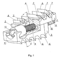
- fig. 1 illustrates the device in a section with a visible driving element and drive-anchoring elements in the form of shelves equipped with shaped cutting knives and with a lock
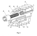
- fig. 2 shows the device in an arrangement with a threaded guideline in the shape of a sleeve and with drive-anchoring elements in the form of uniform shelves
- fig. 3 illustrates the sliding part with a threaded guideline in the form of an open sleeve and with a shelf provided with gaps
- fig. 4 shows an embodiment of the device with drive-anchoring elements in the form of movable shelves on the sliding part and the carrying part.
- the device presented in fig. 1 is composed of a sliding part 1 with a threaded guideline 2,a carrier part 3 and driving element 4 with an external thread provided with a head 5.
- Sliding part 1 and carrying part 3 of the device are provided on the external surface with drive-anchoring elements 6.
- Drive-anchoring elements 6 on device's sliding part 1 are in the form of shelves provided with resistance surfaces and shaped cutting knives 7.
- Sliding part 1 is also provided with at least two shaped elements 8 in the form of cylinder's fragments constituting together with a shaped element 9 in device's carrier part 3 a lock, preventing their separation in the perpendicular direction to the longitudinal axis of the device.
- Head 5 of the driving element 4 is provided with manipulative elements 10 assigned for cooperation with the installation instrument.
- the device shown in an arrangement in fig. 2 is provided on the external surface with drive-anchoring elements 6 in the form of uniform shelves.
- Carrier part 3 of the device is provided with a cylindrical seat 11, shaped element 9 being an element of the lock and longitudinal gap 12 corresponding by shape with the threaded guideline 2 cooperating with it.
- Cylindrical seat 11 cooperating with the head 5 of the driving element 4 has got the diameter and length corresponding with the diameter and length of head 5.
- Sliding part 1 of the device is provided with a cylindrical seat 13 with diameter corresponding with the diameter of head 5 and length longer than head's 5 length and with the shaped element 8 being an element of the lock in the form of cuboid's fragment.
- Threaded guideline 2 is in the form of a sleeve.
- threaded guideline 2 in the sliding part 1 is in the form of a longitudinally opened sleeve, shaped projection 8 in the form of cylinder's fragment, and the external surface of the sliding part 1 is provided with the drive-anchoring element 6 with gaps 14.
- the device has got two drive-anchoring elements 6 articulated with a shaped seat 15 on the external surface of the sliding part 1 and carrier part 3 of the device.
- One of drive-anchoring elements 6 is provided with a resistance projection 16 preventing uncontrolled rotation of the shelf.
Landscapes
- Health & Medical Sciences (AREA)
- Orthopedic Medicine & Surgery (AREA)
- Neurology (AREA)
- Engineering & Computer Science (AREA)
- Biomedical Technology (AREA)
- Life Sciences & Earth Sciences (AREA)
- Animal Behavior & Ethology (AREA)
- Veterinary Medicine (AREA)
- Heart & Thoracic Surgery (AREA)
- Public Health (AREA)
- General Health & Medical Sciences (AREA)
- Cardiology (AREA)
- Surgery (AREA)
- Oral & Maxillofacial Surgery (AREA)
- Transplantation (AREA)
- Vascular Medicine (AREA)
- Molecular Biology (AREA)
- Medical Informatics (AREA)
- Nuclear Medicine, Radiotherapy & Molecular Imaging (AREA)
- Prostheses (AREA)
- Surgical Instruments (AREA)
Description
- This invention relates to surgical displacement of vertebrae, which is applied in surgical treatment of spondylolisthesis. Literature data indicate that sliding of vertebrae occurs on average in 10% of patients treated because of back pain. This pathology may cause a significant disability, both among the youth and adults. Surgical treatment of spondylolisthesis is provided when neurological symptoms and/or pain occur, or even increase, even though conservative treatment had been previously administered. Until now in medical practice, the most commonly used treatment has consisted in bringing the spine to spinal fixation by bone fusion on the sliding level. The spondylodesis itself is not always a sufficient means and does not bring positive results in the form of: restoration of proportions in the height of disc space , thereby reconstruction of the correct geometry, reduction of posture deformation, removal of pain discomfort, restoration of biomechanical balance. To achieve all of the above mentioned benefits, decompression of nerve structures and reposition of the displaced vertebra is essential.
- Devices for spondylolisthesis reposition are known; most of all they are based on different kinds of pulling screws or special repositioning constructions, whose principal feature is a considerably large number of elements and surgical difficulties resulting from the complexity of the system removing this pathology.
- Their application often involves extensive surgical actions, which significantly increase patient's burden and can lead to intra- and postoperative complications.
- An implant, apparatus and a method for spondylolisthesis correction are known from the patent application
WO 96/40016 - An apparatus and a method for the realignment and stabilization of adjacent vertebrae are known from the patent application
US 2008/0319481 . The implant has two halves which are interlocked so that they can slide horizontally with respect to each other. The movement of the implant halves and their respective positions are controlled by a screw set within the implant. The implant includes radial anchors which fit into alignment slots made in the misaligned vertebra. The screw set in the implant is used to advance the halves of the implant which in turn move the misaligned vertebrae back into correct positions. The solution provides for the correction of spondylolisthesis only by means of using the anterior surgical approach, which due to the possibility of disturbing important anatomic structures situated there, seriously hinders and sometimes prevents surgical activities and may pose considerable risk to the patient related i.a. to the prolonged duration of surgery. Another disadvantage of this solution is also the necessity of making an incision - with the use of a special instrument - for slots in the vertebral body for anchors. Yet another drawback is the complicated and difficult to control procedure of introducing the implant into the interbody space, requiring adapting its position to the slots prepared earlier. The screw gear employed allows movement only in one direction - in the direction of the reposition of dislocated vertebrae. As there is no reverse mechanism, intraoperative correction and implant's removal are prevented, resulting in patient risk. Guiding employed in the form of a dove tail does not have any protection against locking of the shift due to the fact that the cooperating implant halves become distant from each other as a result of the elbowing action of the screw. Fixation of vertebrae position and locking of the implant itself require using additional means in the form of a nut and an additional fixing plate, and this increases the number of implant elements and moreover, irritates tissues. - An interbody spacer is known from the patent application
US 2007/0123989 intended for surgical treatment of spondylolisthesis. The spacer is composed of two halves and a locking screw gear, installed using the anterior approach between two vertebrae and anchored in the vertebral body with bone screws in a variant connected with a reduction plate. In the disclosed embodiment, correction of spondylolisthesis is made by manipulating the adjusting mechanism in such a way that the first and the other half move along each other, thus aligning the vertebrae . The locking screw gear may have a central screw, which at rotation can move one of the halves forward or backward. In one embodiment of the screw gear, it can be a central rail allowing the movement of both halves forward and backward, and the mechanism can be secured by a lateral blockage. The adjusting mechanism employed does not offer the possibility of moving the halves along each other in opposite directions. Another disadvantage of this solution is the mechanism of anchoring the interbody spacer in the vertebral body, which does not provide a secure fixation during reposition and causes spacer's elements to project from vertebral margins after reduction of pathology, thus endangering biological structures situated in this area. -
US 6,533,791 B1 describes an instrument system for the operative correction of vertebral displacements and for stabilizing of repositioned vertebral bodies. The system comprises correction and support devices which are formed in two parts and which are displaceable in the axial direction guided relative to one another by means of an integrated setting member. -
US 2009/0125062 A1 describes a spinal implant having a post-operative adjustable dimension. The spinal implant includes an upper support plate and a lower support blade, the lower support plate including a recess in which an electrical motor is mounted. The electrical motor turns a screw which causes the first support plate to slide with respect to the second support blade. - Free of the above mentioned inconveniences is a device, namely an implant for surgical displacement of vertebrae, which is composed of two parts co-working in a sliding way : a sliding part with an internal thread and a carrier part, and also a driving element with an external thread which is located between the parts. According to the invention, the driving element is provided with a head, whereas the sliding part of the device is equipped with a threaded guideline cooperating with the driving element and a seat of a diameter corresponding with the head's diameter and length greater than the head's length, and the carrier part has a seat of a diameter and length corresponding with the head's diameter and length. Furthermore, the sliding part and the carrier part are provided with cooperating shaped elements, which form a lock preventing separation of both parts in the direction perpendicular to the device longitudinal axis during performance of corrective actions. The lock is formed by at least one element, which is located in the sliding part and one element in the carrier part. In one embodiment of the device, the element of the lock located in the sliding part of the device is in the form of a cylinder. In another embodiment, the shaped element is in the form of a fragment of a cuboid.
- The threaded guideline in the sliding part and carrier part is in the form of a sleeve. Preferably, this sleeve can be open longitudinally.
- The external surface of the sliding part and carrier part is provided with drive-anchoring elements, which are in the form of shelves provided with resistance surfaces and at least one shaped cutting knife. In one embodiment of the device, the drive-anchoring elements are provided with gaps. In another embodiment, at least one shelf is articulated with a shaped seat on the external surface of the device. Preferably, the movable shelf is provided with a resistance projection. The drive-anchoring elements, which constitute the outfit of the external part of the device's sliding part, are located at an angle of 0 up to 100°, and the drive-anchoring elements of the carrier part are situated at an angle of 0 up to 100° in relation to the external surface.
- The device for the treatment of spondylolisthesis by surgical displacement of vertebrae according to the invention is characterized in that it has a simple and compact construction limiting the area of surgical intervention, thus invasiveness of the procedure is decreased. It enables surgeries to be performed both using the posterior and anterior approach, depending on medical needs and recommendations. At the same time, it ensures decompression of compressed nerve structures, restoration of correct anatomical proportions and final blocking of the whole system, preventing secondary slippage without any additional accompanying elements, and this in turn decreases the risk related to the necessity of cooperation of all the elements of the stabilizing system.
- The construction of the threaded guideline of the motion driving element according to the invention secures the drive-repositioning system against blocking, thus increasing the safety of the displacement of vertebrae being performed.
- A simple and safe seating of the implant in the interbody space shortens the duration of surgery and minimizes patient's burden, increasing his safety. The construction of the implant satisfies biomechanical requirements for stabilization and is adapted to the anatomical shape of the interbody space, which ensures effectiveness of treatment of patients at any age.
- The invention is disclosed in examples of implementation in the accompanying figures, where
fig. 1 illustrates the device in a section with a visible driving element and drive-anchoring elements in the form of shelves equipped with shaped cutting knives and with a lock;fig. 2 shows the device in an arrangement with a threaded guideline in the shape of a sleeve and with drive-anchoring elements in the form of uniform shelves;fig. 3 illustrates the sliding part with a threaded guideline in the form of an open sleeve and with a shelf provided with gaps;fig. 4 shows an embodiment of the device with drive-anchoring elements in the form of movable shelves on the sliding part and the carrying part. - The device presented in
fig. 1 is composed of a sliding part 1 with a threadedguideline 2,acarrier part 3 and drivingelement 4 with an external thread provided with ahead 5. Sliding part 1 and carryingpart 3 of the device are provided on the external surface with drive-anchoringelements 6. Drive-anchoring elements 6 on device's sliding part 1 are in the form of shelves provided with resistance surfaces andshaped cutting knives 7. Sliding part 1 is also provided with at least twoshaped elements 8 in the form of cylinder's fragments constituting together with ashaped element 9 in device's carrier part 3 a lock, preventing their separation in the perpendicular direction to the longitudinal axis of the device.Head 5 of thedriving element 4 is provided withmanipulative elements 10 assigned for cooperation with the installation instrument. - The device shown in an arrangement in
fig. 2 is provided on the external surface with drive-anchoringelements 6 in the form of uniform shelves.Carrier part 3 of the device is provided with acylindrical seat 11,shaped element 9 being an element of the lock andlongitudinal gap 12 corresponding by shape with the threadedguideline 2 cooperating with it.Cylindrical seat 11 cooperating with thehead 5 of thedriving element 4 has got the diameter and length corresponding with the diameter and length ofhead 5. Sliding part 1 of the device is provided with acylindrical seat 13 with diameter corresponding with the diameter ofhead 5 and length longer than head's 5 length and with theshaped element 8 being an element of the lock in the form of cuboid's fragment. Threadedguideline 2 is in the form of a sleeve. - In another embodiment presented in
fig. 3 , threadedguideline 2 in the sliding part 1 is in the form of a longitudinally opened sleeve, shapedprojection 8 in the form of cylinder's fragment, and the external surface of the sliding part 1 is provided with the drive-anchoringelement 6 withgaps 14. - In the embodiment shown in
fig. 4 , the device has got two drive-anchoringelements 6 articulated with a shapedseat 15 on the external surface of the sliding part 1 andcarrier part 3 of the device. One of drive-anchoringelements 6 is provided with aresistance projection 16 preventing uncontrolled rotation of the shelf.
Claims (10)
- A device for a surgical displacement of vertebrae, containing two parts cooperating in a sliding way:- a sliding part with an internal thread,- a carrier part, and- a driving element with an external thread located between them,where:- the sliding part (1) of the device is provided with a threaded guideline (2) cooperating with the driving element (4),- the driving element (4) is provided with a head (5),- the carrier part (3) of the device has got a cylindrical seat (11) with the diameter and length corresponding with head's (5) diameter and length, and- the sliding part (1) and carrier part (3) are provided with cooperating elements: at least one first shaped element (8) and a second shaped element (9) constituting a lock preventing separation of the parts (1, 3) in the perpendicular direction to the longitudinal axis of the device,characterised in that
the sliding part (1) of the device is provided with a seat (13) of the diameter corresponding with the diameter of head (5), and with length larger than head's (5) length. - The device according to claim 1 is characterized in that the threaded guideline (2) in the sliding part (1) of the device is in the form of a sleeve.
- The device according to claim 2 is characterized in that the threaded guideline (2) in the sliding part (1) of the device is in the form of a longitudinally open sleeve.
- The device according to claim 1 is characterized in that the shaped element (8) is in the form of a cylinder's fragment.
- The device according to claim 1 is characterized in that the shaped element (8) is in the form of a cuboid's fragment.
- The device according to claim 1 is characterized in that the carrier part (3) and sliding part (1) are provided with drive-anchoring elements (6) on the external surface.
- The device according to claim 6 is characterized in that drive-anchoring elements (6) are in the form of shelves provided with resistance areas and at least one shaped cutting knife (7)
- The device according to claim 6 is characterized in that drive-anchoring elements (6) contain gaps (14).
- The device according to claim 7 and 8 is characterized in that at least one drive-anchoring element (6) is articulated with a shaped seat (15) on the external surface of the device and moreover, it is provided with a resistance projection (16).
- The device according to claim 7 is characterized in that drive-anchoring elements (6) constituting the outfit of the external surface of the sliding part (1) of the device are located at an angle (α) of 0° up to 110°, and drive-anchoring elements (6) of the carrier part (3) of the device are arranged at an angle (β) of 0°up to 110° with relation to the external surface.
Applications Claiming Priority (2)
| Application Number | Priority Date | Filing Date | Title |
|---|---|---|---|
| PL389148A PL215752B1 (en) | 2009-09-28 | 2009-09-28 | Equipment for surgical vertebra movement |
| PCT/PL2010/000097 WO2011037484A1 (en) | 2009-09-28 | 2010-09-23 | Device for surgical displacement of vertebrae |
Publications (2)
| Publication Number | Publication Date |
|---|---|
| EP2482764A1 EP2482764A1 (en) | 2012-08-08 |
| EP2482764B1 true EP2482764B1 (en) | 2015-03-18 |
Family
ID=43416253
Family Applications (1)
| Application Number | Title | Priority Date | Filing Date |
|---|---|---|---|
| EP10769086.9A Not-in-force EP2482764B1 (en) | 2009-09-28 | 2010-09-23 | Device for surgical displacement of vertebrae |
Country Status (14)
| Country | Link |
|---|---|
| US (1) | US8556975B2 (en) |
| EP (1) | EP2482764B1 (en) |
| KR (1) | KR101717951B1 (en) |
| CN (1) | CN102573705B (en) |
| AU (1) | AU2010298820B2 (en) |
| BR (1) | BR112012007609A2 (en) |
| CA (1) | CA2775785C (en) |
| ES (1) | ES2538102T3 (en) |
| IL (1) | IL218864A (en) |
| IN (1) | IN2012DN02194A (en) |
| MX (1) | MX2012003717A (en) |
| PL (1) | PL215752B1 (en) |
| RU (1) | RU2561536C2 (en) |
| WO (1) | WO2011037484A1 (en) |
Families Citing this family (102)
| Publication number | Priority date | Publication date | Assignee | Title |
|---|---|---|---|---|
| FR2897259B1 (en) | 2006-02-15 | 2008-05-09 | Ldr Medical Soc Par Actions Si | INTERSOMATIC TRANSFORAMINAL CAGE WITH INTERBREBAL FUSION GRAFT AND CAGE IMPLANTATION INSTRUMENT |
| FR2824261B1 (en) | 2001-05-04 | 2004-05-28 | Ldr Medical | INTERVERTEBRAL DISC PROSTHESIS AND IMPLEMENTATION METHOD AND TOOLS |
| FR2827156B1 (en) | 2001-07-13 | 2003-11-14 | Ldr Medical | VERTEBRAL CAGE DEVICE WITH MODULAR FASTENING |
| FR2846550B1 (en) | 2002-11-05 | 2006-01-13 | Ldr Medical | INTERVERTEBRAL DISC PROSTHESIS |
| FR2865629B1 (en) | 2004-02-04 | 2007-01-26 | Ldr Medical | INTERVERTEBRAL DISC PROSTHESIS |
| KR101146215B1 (en) | 2004-02-04 | 2012-05-11 | 엘디알 메디칼 | Intervertebral disc prosthesis |
| FR2869528B1 (en) | 2004-04-28 | 2007-02-02 | Ldr Medical | INTERVERTEBRAL DISC PROSTHESIS |
| US7955357B2 (en) | 2004-07-02 | 2011-06-07 | Ellipse Technologies, Inc. | Expandable rod system to treat scoliosis and method of using the same |
| US8597360B2 (en) | 2004-11-03 | 2013-12-03 | Neuropro Technologies, Inc. | Bone fusion device |
| FR2879436B1 (en) * | 2004-12-22 | 2007-03-09 | Ldr Medical | INTERVERTEBRAL DISC PROSTHESIS |
| FR2891135B1 (en) | 2005-09-23 | 2008-09-12 | Ldr Medical Sarl | INTERVERTEBRAL DISC PROSTHESIS |
| FR2893838B1 (en) | 2005-11-30 | 2008-08-08 | Ldr Medical Soc Par Actions Si | PROSTHESIS OF INTERVERTEBRAL DISC AND INSTRUMENTATION OF INSERTION OF THE PROSTHESIS BETWEEN VERTEBRATES |
| US9526525B2 (en) | 2006-08-22 | 2016-12-27 | Neuropro Technologies, Inc. | Percutaneous system for dynamic spinal stabilization |
| US7862502B2 (en) | 2006-10-20 | 2011-01-04 | Ellipse Technologies, Inc. | Method and apparatus for adjusting a gastrointestinal restriction device |
| US8465546B2 (en) | 2007-02-16 | 2013-06-18 | Ldr Medical | Intervertebral disc prosthesis insertion assemblies |
| FR2916956B1 (en) | 2007-06-08 | 2012-12-14 | Ldr Medical | INTERSOMATIC CAGE, INTERVERTEBRAL PROSTHESIS, ANCHORING DEVICE AND IMPLANTATION INSTRUMENTATION |
| US20090112263A1 (en) | 2007-10-30 | 2009-04-30 | Scott Pool | Skeletal manipulation system |
| US11202707B2 (en) | 2008-03-25 | 2021-12-21 | Nuvasive Specialized Orthopedics, Inc. | Adjustable implant system |
| US11241257B2 (en) | 2008-10-13 | 2022-02-08 | Nuvasive Specialized Orthopedics, Inc. | Spinal distraction system |
| US8382756B2 (en) | 2008-11-10 | 2013-02-26 | Ellipse Technologies, Inc. | External adjustment device for distraction device |
| US8197490B2 (en) | 2009-02-23 | 2012-06-12 | Ellipse Technologies, Inc. | Non-invasive adjustable distraction system |
| US9622792B2 (en) | 2009-04-29 | 2017-04-18 | Nuvasive Specialized Orthopedics, Inc. | Interspinous process device and method |
| EP2473116B1 (en) | 2009-09-04 | 2019-12-04 | NuVasive Specialized Orthopedics, Inc. | Bone growth device |
| CA2773723C (en) | 2009-09-17 | 2017-10-31 | Synthes Usa, Llc | Intervertebral implant having extendable bone fixation members |
| US10973656B2 (en) | 2009-09-18 | 2021-04-13 | Spinal Surgical Strategies, Inc. | Bone graft delivery system and method for using same |
| US10245159B1 (en) | 2009-09-18 | 2019-04-02 | Spinal Surgical Strategies, Llc | Bone graft delivery system and method for using same |
| US8906028B2 (en) | 2009-09-18 | 2014-12-09 | Spinal Surgical Strategies, Llc | Bone graft delivery device and method of using the same |
| JP5647264B2 (en) | 2009-12-31 | 2014-12-24 | エル・デ・エール・メデイカル | Fixation devices, intervertebral implants, and implantable devices |
| US9248043B2 (en) | 2010-06-30 | 2016-02-02 | Ellipse Technologies, Inc. | External adjustment device for distraction device |
| WO2012021378A2 (en) | 2010-08-09 | 2012-02-16 | Ellipse Technologies, Inc. | Maintenance feature in magnetic implant |
| WO2012112396A2 (en) | 2011-02-14 | 2012-08-23 | Ellipse Technologies, Inc. | Device and method for treating fractured bones |
| PL218347B1 (en) * | 2011-05-12 | 2014-11-28 | Lfc Spółka Z Ograniczoną Odpowiedzialnością | Intervertebral implant for positioning of adjacent vertebrae |
| WO2013023096A1 (en) | 2011-08-09 | 2013-02-14 | Neuropro Technologies, Inc. | Bone fusion device, system and method |
| US10420654B2 (en) | 2011-08-09 | 2019-09-24 | Neuropro Technologies, Inc. | Bone fusion device, system and method |
| US9358123B2 (en) | 2011-08-09 | 2016-06-07 | Neuropro Spinal Jaxx, Inc. | Bone fusion device, apparatus and method |
| US10743794B2 (en) | 2011-10-04 | 2020-08-18 | Nuvasive Specialized Orthopedics, Inc. | Devices and methods for non-invasive implant length sensing |
| US10016220B2 (en) | 2011-11-01 | 2018-07-10 | Nuvasive Specialized Orthopedics, Inc. | Adjustable magnetic devices and methods of using same |
| FR2987256B1 (en) | 2012-02-24 | 2014-08-08 | Ldr Medical | ANCHORING DEVICE FOR INTERVERTEBRAL IMPLANT, INTERVERTEBRAL IMPLANT AND IMPLANTATION INSTRUMENTATION |
| US9532883B2 (en) | 2012-04-13 | 2017-01-03 | Neuropro Technologies, Inc. | Bone fusion device |
| US10159583B2 (en) | 2012-04-13 | 2018-12-25 | Neuropro Technologies, Inc. | Bone fusion device |
| WO2013159823A1 (en) | 2012-04-27 | 2013-10-31 | Lfc Spólka Z O.O. | Intervertebral implant, instrument for use in placing it |
| US10709482B2 (en) * | 2012-05-30 | 2020-07-14 | Globus Medical, Inc. | Laminoplasty system |
| US20130325071A1 (en) | 2012-05-30 | 2013-12-05 | Marcin Niemiec | Aligning Vertebral Bodies |
| US20130338714A1 (en) | 2012-06-15 | 2013-12-19 | Arvin Chang | Magnetic implants with improved anatomical compatibility |
| US9044281B2 (en) | 2012-10-18 | 2015-06-02 | Ellipse Technologies, Inc. | Intramedullary implants for replacing lost bone |
| CN104902854B (en) | 2012-10-29 | 2017-10-03 | 诺威适骨科专科公司 | Adjustable device for knee arthritis |
| US9585765B2 (en) * | 2013-02-14 | 2017-03-07 | Globus Medical, Inc | Devices and methods for correcting vertebral misalignment |
| FR3002135B1 (en) * | 2013-02-19 | 2016-02-05 | Neuro France Implants Nfi | POSTERO LATERAL INTERSOMATIC CAGE FOR REALIZING VERTEBRAL ARTHRODESIS |
| US9179938B2 (en) | 2013-03-08 | 2015-11-10 | Ellipse Technologies, Inc. | Distraction devices and method of assembling the same |
| US12193948B2 (en) | 2013-03-13 | 2025-01-14 | Life Spine, Inc. | Expandable implant assembly |
| US10426632B2 (en) | 2013-03-13 | 2019-10-01 | Life Spine, Inc. | Expandable spinal interbody assembly |
| US11304818B2 (en) | 2013-03-13 | 2022-04-19 | Life Spine, Inc. | Expandable spinal interbody assembly |
| US10098757B2 (en) | 2013-03-15 | 2018-10-16 | Neuropro Technologies Inc. | Bodiless bone fusion device, apparatus and method |
| US9149368B1 (en) * | 2013-03-15 | 2015-10-06 | Wade K. Jensen | Spondylolithesis reduction spinal insert fusion cage and method of reducing spondylolithesis |
| FR3005569B1 (en) | 2013-05-16 | 2021-09-03 | Ldr Medical | VERTEBRAL IMPLANT, VERTEBRAL IMPLANT FIXATION DEVICE AND IMPLANTATION INSTRUMENTATION |
| US9788971B1 (en) | 2013-05-22 | 2017-10-17 | Nuvasive, Inc. | Expandable fusion implant and related methods |
| US10226242B2 (en) | 2013-07-31 | 2019-03-12 | Nuvasive Specialized Orthopedics, Inc. | Noninvasively adjustable suture anchors |
| US9801734B1 (en) | 2013-08-09 | 2017-10-31 | Nuvasive, Inc. | Lordotic expandable interbody implant |
| US10751094B2 (en) | 2013-10-10 | 2020-08-25 | Nuvasive Specialized Orthopedics, Inc. | Adjustable spinal implant |
| US9198774B2 (en) * | 2013-11-21 | 2015-12-01 | Perumala Corporation | Intervertebral disk cage and stabilizer |
| FR3016793B1 (en) | 2014-01-30 | 2021-05-07 | Ldr Medical | ANCHORING DEVICE FOR SPINAL IMPLANT, SPINAL IMPLANT AND IMPLANTATION INSTRUMENTATION |
| CN111345867A (en) | 2014-04-28 | 2020-06-30 | 诺威适骨科专科公司 | remote control |
| FR3020756B1 (en) | 2014-05-06 | 2022-03-11 | Ldr Medical | VERTEBRAL IMPLANT, VERTEBRAL IMPLANT FIXATION DEVICE AND IMPLANT INSTRUMENTATION |
| WO2016063283A1 (en) * | 2014-10-21 | 2016-04-28 | Nlt Spine Ltd. | Adjustable implant |
| KR102588501B1 (en) | 2014-10-23 | 2023-10-11 | 누베이시브 스페셜라이즈드 오소페딕스, 인크. | Remotely adjustable interactive bone reshaping implant |
| EP4005515B1 (en) | 2014-12-26 | 2024-07-24 | NuVasive Specialized Orthopedics, Inc. | Systems for distraction |
| US10238427B2 (en) | 2015-02-19 | 2019-03-26 | Nuvasive Specialized Orthopedics, Inc. | Systems and methods for vertebral adjustment |
| US20180049754A1 (en) * | 2015-03-13 | 2018-02-22 | Redemed S.R.L. | Intervertebral prosthesis, apparatus for implanting intervertebral prostheses and surgical method for implanting intervertebral prostheses, particularly for percutaneous mini-invasive surgery procedures |
| US10123829B1 (en) | 2015-06-15 | 2018-11-13 | Nuvasive, Inc. | Reduction instruments and methods |
| WO2017009840A1 (en) | 2015-07-14 | 2017-01-19 | Nlt Spine Ltd. | Expandable implant with deflectable sequence of segments |
| WO2017066774A1 (en) | 2015-10-16 | 2017-04-20 | Nuvasive Specialized Orthopedics, Inc. | Adjustable devices for treating arthritis of the knee |
| JP6953409B2 (en) | 2015-12-10 | 2021-10-27 | ニューベイシブ スペシャライズド オーソペディックス,インコーポレイテッド | External adjustment device for extension device |
| DE102015121658A1 (en) * | 2015-12-11 | 2017-06-14 | Aesculap Ag | Artificial joint implant and hip joint endoprosthesis |
| DK3407812T3 (en) | 2016-01-28 | 2020-09-21 | Nuvasive Specialized Orthopedics Inc | Bone transport system |
| WO2017139548A1 (en) | 2016-02-10 | 2017-08-17 | Nuvasive Specialized Orthopedics, Inc. | Systems and methods for controlling multiple surgical variables |
| US10973657B2 (en) | 2017-01-18 | 2021-04-13 | Neuropro Technologies, Inc. | Bone fusion surgical system and method |
| US10729560B2 (en) | 2017-01-18 | 2020-08-04 | Neuropro Technologies, Inc. | Bone fusion system, device and method including an insertion instrument |
| US10213321B2 (en) | 2017-01-18 | 2019-02-26 | Neuropro Technologies, Inc. | Bone fusion system, device and method including delivery apparatus |
| US10111760B2 (en) | 2017-01-18 | 2018-10-30 | Neuropro Technologies, Inc. | Bone fusion system, device and method including a measuring mechanism |
| US11896494B2 (en) | 2017-07-10 | 2024-02-13 | Life Spine, Inc. | Expandable implant assembly |
| US11033403B2 (en) | 2017-07-10 | 2021-06-15 | Life Spine, Inc. | Expandable implant assembly |
| EP3922039A1 (en) | 2019-02-07 | 2021-12-15 | NuVasive Specialized Orthopedics, Inc. | Ultrasonic communication in medical devices |
| US11589901B2 (en) | 2019-02-08 | 2023-02-28 | Nuvasive Specialized Orthopedics, Inc. | External adjustment device |
| WO2020251943A1 (en) | 2019-06-10 | 2020-12-17 | Life Spine, Inc. | Expandable implant assembly with compression features |
| US12042395B2 (en) | 2019-06-11 | 2024-07-23 | Life Spine, Inc. | Expandable implant assembly |
| WO2020252040A1 (en) * | 2019-06-11 | 2020-12-17 | Life Spine, Inc. | Expandable implant assembly |
| WO2021045946A1 (en) | 2019-09-03 | 2021-03-11 | Nuvasive Specialized Orthopedics, Inc. | Acoustic reporting for dynamic implants |
| US11857432B2 (en) | 2020-04-13 | 2024-01-02 | Life Spine, Inc. | Expandable implant assembly |
| US11602439B2 (en) | 2020-04-16 | 2023-03-14 | Life Spine, Inc. | Expandable implant assembly |
| US12336917B2 (en) | 2020-05-15 | 2025-06-24 | Life Spine, Inc. | Steerable implant assembly |
| US11602440B2 (en) | 2020-06-25 | 2023-03-14 | Life Spine, Inc. | Expandable implant assembly |
| US12605192B2 (en) | 2020-07-15 | 2026-04-21 | Globus Medical, Inc. | Ultrasonic communication in adjustable implants |
| US12213708B2 (en) | 2020-09-08 | 2025-02-04 | Nuvasive Specialized Orthopedics, Inc. | Remote control module for adjustable implants |
| US11554020B2 (en) | 2020-09-08 | 2023-01-17 | Life Spine, Inc. | Expandable implant with pivoting control assembly |
| US11806054B2 (en) | 2021-02-23 | 2023-11-07 | Nuvasive Specialized Orthopedics, Inc. | Adjustable implant, system and methods |
| US11737787B1 (en) | 2021-05-27 | 2023-08-29 | Nuvasive, Inc. | Bone elongating devices and methods of use |
| AU2022325024A1 (en) | 2021-08-03 | 2024-02-22 | Nuvasive Specialized Orthopedics, Inc. | Adjustable implant |
| US12551240B2 (en) | 2022-06-13 | 2026-02-17 | Nuvasive Inc. | Distraction loss magnet on-off mechanism |
| US12458417B2 (en) | 2022-08-15 | 2025-11-04 | Nuvasive Specialized Orthopedics Inc. | Intermedullary lengthening implant with integrated load sensor |
| US12508058B2 (en) | 2022-10-07 | 2025-12-30 | Nuvasive Specialized Orthopedics, Inc. | Adjustable tether implant |
| US12558133B2 (en) | 2023-04-25 | 2026-02-24 | Nuvasive, Inc. | Flat plate mechanisms for bone lengthening |
| US12533164B2 (en) | 2023-05-03 | 2026-01-27 | Nuvasive Specialized Orthopedics, Inc. | Adjustable implant |
Family Cites Families (20)
| Publication number | Priority date | Publication date | Assignee | Title |
|---|---|---|---|---|
| US5653762A (en) | 1994-03-18 | 1997-08-05 | Pisharodi; Madhavan | Method of stabilizing adjacent vertebrae with rotating, lockable, middle-expanded intervertebral disk stabilizer |
| RU2097007C1 (en) * | 1994-05-11 | 1997-11-27 | Кедров Андрей Владимирович | Internal vertebral fixing device |
| DE19750382A1 (en) * | 1997-11-13 | 1999-05-20 | Augustin Prof Dr Med Betz | Operative correction equipment for displaced vertebrae used in minimally invasive surgery |
| ATE235863T1 (en) * | 1999-05-21 | 2003-04-15 | Link Waldemar Gmbh Co | INTERVERBARY ENDOPROSTHESIS WITH A TOOTHED CONNECTION PLATE |
| US6491695B1 (en) * | 1999-11-05 | 2002-12-10 | Carl Roggenbuck | Apparatus and method for aligning vertebrae |
| US7153303B2 (en) * | 2002-06-19 | 2006-12-26 | Sdgi Holdings, Inc. | Guide and blade for contouring vertebral bodies |
| US20040073214A1 (en) * | 2002-10-10 | 2004-04-15 | Mehdizadeh Hamid M. | Spondylolisthesis correction apparatus and method |
| WO2004037067A2 (en) * | 2002-10-21 | 2004-05-06 | 3Hbfm, Llc | Intervertebral disk prosthesis |
| RU2251996C2 (en) * | 2003-01-20 | 2005-05-20 | Кравченко Юрий Владимирович | Device for carrying out cervical vertebrae fixation |
| US7713304B2 (en) * | 2003-07-31 | 2010-05-11 | Globus Medical, Inc. | Transforaminal prosthetic spinal disc replacement |
| WO2005044152A1 (en) * | 2003-11-07 | 2005-05-19 | Impliant Ltd. | Spinal prostheses |
| US7850733B2 (en) * | 2004-02-10 | 2010-12-14 | Atlas Spine, Inc. | PLIF opposing wedge ramp |
| US7211112B2 (en) * | 2004-02-10 | 2007-05-01 | Atlas Spine | Spinal fusion device |
| CN100591305C (en) * | 2004-02-13 | 2010-02-24 | 小弗朗茨·科波夫 | Intervertebral implant and surgical method for lumbar spinal fusion |
| US7531002B2 (en) * | 2004-04-16 | 2009-05-12 | Depuy Spine, Inc. | Intervertebral disc with monitoring and adjusting capabilities |
| US7942903B2 (en) * | 2005-04-12 | 2011-05-17 | Moskowitz Ahmnon D | Bi-directional fixating transvertebral body screws and posterior cervical and lumbar interarticulating joint calibrated stapling devices for spinal fusion |
| US20070123989A1 (en) | 2005-10-21 | 2007-05-31 | Synthes (U.S.A.) | Method and instruments to treat spondylolisthesis by an anterior minimally invasive approach of the spine |
| US20080051902A1 (en) * | 2006-08-10 | 2008-02-28 | James Dwyer | Modular intervertebral disc prosthesis and method of replacing an intervertebral disc |
| US7744649B2 (en) * | 2007-06-25 | 2010-06-29 | Moore Mark R | Spondylolisthesis correction apparatus and method |
| US8241331B2 (en) * | 2007-11-08 | 2012-08-14 | Spine21 Ltd. | Spinal implant having a post-operative adjustable dimension |
-
2009
- 2009-09-28 PL PL389148A patent/PL215752B1/en unknown
-
2010
- 2010-09-23 ES ES10769086.9T patent/ES2538102T3/en active Active
- 2010-09-23 IN IN2194DEN2012 patent/IN2012DN02194A/en unknown
- 2010-09-23 US US12/889,314 patent/US8556975B2/en not_active Expired - Fee Related
- 2010-09-23 MX MX2012003717A patent/MX2012003717A/en active IP Right Grant
- 2010-09-23 BR BR112012007609A patent/BR112012007609A2/en not_active IP Right Cessation
- 2010-09-23 CA CA2775785A patent/CA2775785C/en not_active Expired - Fee Related
- 2010-09-23 RU RU2012110891/14A patent/RU2561536C2/en not_active IP Right Cessation
- 2010-09-23 CN CN201080042893.6A patent/CN102573705B/en not_active Expired - Fee Related
- 2010-09-23 EP EP10769086.9A patent/EP2482764B1/en not_active Not-in-force
- 2010-09-23 WO PCT/PL2010/000097 patent/WO2011037484A1/en not_active Ceased
- 2010-09-23 KR KR1020127006795A patent/KR101717951B1/en not_active Expired - Fee Related
- 2010-09-23 AU AU2010298820A patent/AU2010298820B2/en not_active Ceased
-
2012
- 2012-03-27 IL IL218864A patent/IL218864A/en not_active IP Right Cessation
Also Published As
| Publication number | Publication date |
|---|---|
| CA2775785A1 (en) | 2011-03-31 |
| PL215752B1 (en) | 2014-01-31 |
| KR20120093166A (en) | 2012-08-22 |
| US8556975B2 (en) | 2013-10-15 |
| ES2538102T3 (en) | 2015-06-17 |
| CN102573705A (en) | 2012-07-11 |
| RU2012110891A (en) | 2013-11-10 |
| MX2012003717A (en) | 2012-08-23 |
| WO2011037484A1 (en) | 2011-03-31 |
| CA2775785C (en) | 2014-08-12 |
| KR101717951B1 (en) | 2017-03-20 |
| RU2561536C2 (en) | 2015-08-27 |
| CN102573705B (en) | 2014-07-02 |
| IL218864A (en) | 2015-05-31 |
| AU2010298820A1 (en) | 2012-04-05 |
| BR112012007609A2 (en) | 2016-08-23 |
| EP2482764A1 (en) | 2012-08-08 |
| IL218864A0 (en) | 2012-06-28 |
| US20110077738A1 (en) | 2011-03-31 |
| AU2010298820B2 (en) | 2016-02-04 |
| IN2012DN02194A (en) | 2015-08-21 |
| PL389148A1 (en) | 2011-04-11 |
Similar Documents
| Publication | Publication Date | Title |
|---|---|---|
| CA2775785C (en) | Device for surgical displacement of vertebrae | |
| US8870920B2 (en) | Devices and methods for inter-vertebral orthopedic device placement | |
| US7896906B2 (en) | Artificial facet joint | |
| US20190314062A1 (en) | Dynamic Plate With Inserts | |
| CN108498150A (en) | spinal implant system and method | |
| WO2012024335A2 (en) | System and method for aligning vertebrae in the amelioration of aberrant spinal column deviation conditions in patients requiring the accomodation of spinal column growth or elongation | |
| US20100036434A1 (en) | Rescue reduction bone anchor | |
| WO2004108015A2 (en) | Artificial disc replacements with oblique keels | |
| CN113710174B (en) | Surgical systems and methods | |
| AU2017281696B2 (en) | Method and apparatus for spinal facet fusion | |
| CN113710175A (en) | Surgical system and method | |
| CN113710176A (en) | Surgical system and method | |
| US9968460B2 (en) | Dynamic spinal segment replacement | |
| EP3434211A1 (en) | Spinal stabilization device | |
| EP3015084B1 (en) | Spinal fixation member | |
| Chen et al. | Complications associated with posterior lumbar interbody fusion using Bagby and Kuslich method for treatment of spondylolisthesis | |
| JP2019533484A (en) | Anterior spinal transplantation and related systems and methods for reducing spinal alignment abnormalities | |
| CN109561971B (en) | Spinal implant with compression prevention | |
| EP4013321B1 (en) | Pedicle fixation system | |
| EP2939622A1 (en) | System for correction of the spine curvatures | |
| WO2023079508A1 (en) | Surgical instrument and method |
Legal Events
| Date | Code | Title | Description |
|---|---|---|---|
| PUAI | Public reference made under article 153(3) epc to a published international application that has entered the european phase |
Free format text: ORIGINAL CODE: 0009012 |
|
| 17P | Request for examination filed |
Effective date: 20120329 |
|
| AK | Designated contracting states |
Kind code of ref document: A1 Designated state(s): AL AT BE BG CH CY CZ DE DK EE ES FI FR GB GR HR HU IE IS IT LI LT LU LV MC MK MT NL NO PL PT RO SE SI SK SM TR |
|
| DAX | Request for extension of the european patent (deleted) | ||
| REG | Reference to a national code |
Ref country code: DE Ref legal event code: R079 Ref document number: 602010023232 Country of ref document: DE Free format text: PREVIOUS MAIN CLASS: A61F0002440000 Ipc: A61B0017020000 |
|
| GRAP | Despatch of communication of intention to grant a patent |
Free format text: ORIGINAL CODE: EPIDOSNIGR1 |
|
| RIC1 | Information provided on ipc code assigned before grant |
Ipc: A61F 2/30 20060101ALI20140929BHEP Ipc: A61B 17/02 20060101AFI20140929BHEP Ipc: A61F 2/44 20060101ALI20140929BHEP |
|
| INTG | Intention to grant announced |
Effective date: 20141017 |
|
| GRAS | Grant fee paid |
Free format text: ORIGINAL CODE: EPIDOSNIGR3 |
|
| GRAA | (expected) grant |
Free format text: ORIGINAL CODE: 0009210 |
|
| AK | Designated contracting states |
Kind code of ref document: B1 Designated state(s): AL AT BE BG CH CY CZ DE DK EE ES FI FR GB GR HR HU IE IS IT LI LT LU LV MC MK MT NL NO PL PT RO SE SI SK SM TR |
|
| REG | Reference to a national code |
Ref country code: GB Ref legal event code: FG4D |
|
| REG | Reference to a national code |
Ref country code: CH Ref legal event code: EP |
|
| REG | Reference to a national code |
Ref country code: IE Ref legal event code: FG4D |
|
| REG | Reference to a national code |
Ref country code: AT Ref legal event code: REF Ref document number: 716017 Country of ref document: AT Kind code of ref document: T Effective date: 20150415 |
|
| REG | Reference to a national code |
Ref country code: DE Ref legal event code: R096 Ref document number: 602010023232 Country of ref document: DE Effective date: 20150430 |
|
| REG | Reference to a national code |
Ref country code: SE Ref legal event code: TRGR |
|
| REG | Reference to a national code |
Ref country code: ES Ref legal event code: FG2A Ref document number: 2538102 Country of ref document: ES Kind code of ref document: T3 Effective date: 20150617 |
|
| REG | Reference to a national code |
Ref country code: NL Ref legal event code: VDEP Effective date: 20150318 |
|
| REG | Reference to a national code |
Ref country code: NL Ref legal event code: VDEP Effective date: 20150318 |
|
| PG25 | Lapsed in a contracting state [announced via postgrant information from national office to epo] |
Ref country code: HR Free format text: LAPSE BECAUSE OF FAILURE TO SUBMIT A TRANSLATION OF THE DESCRIPTION OR TO PAY THE FEE WITHIN THE PRESCRIBED TIME-LIMIT Effective date: 20150318 Ref country code: LT Free format text: LAPSE BECAUSE OF FAILURE TO SUBMIT A TRANSLATION OF THE DESCRIPTION OR TO PAY THE FEE WITHIN THE PRESCRIBED TIME-LIMIT Effective date: 20150318 Ref country code: FI Free format text: LAPSE BECAUSE OF FAILURE TO SUBMIT A TRANSLATION OF THE DESCRIPTION OR TO PAY THE FEE WITHIN THE PRESCRIBED TIME-LIMIT Effective date: 20150318 Ref country code: NO Free format text: LAPSE BECAUSE OF FAILURE TO SUBMIT A TRANSLATION OF THE DESCRIPTION OR TO PAY THE FEE WITHIN THE PRESCRIBED TIME-LIMIT Effective date: 20150618 |
|
| REG | Reference to a national code |
Ref country code: AT Ref legal event code: MK05 Ref document number: 716017 Country of ref document: AT Kind code of ref document: T Effective date: 20150318 |
|
| REG | Reference to a national code |
Ref country code: LT Ref legal event code: MG4D |
|
| PG25 | Lapsed in a contracting state [announced via postgrant information from national office to epo] |
Ref country code: GR Free format text: LAPSE BECAUSE OF FAILURE TO SUBMIT A TRANSLATION OF THE DESCRIPTION OR TO PAY THE FEE WITHIN THE PRESCRIBED TIME-LIMIT Effective date: 20150619 Ref country code: LV Free format text: LAPSE BECAUSE OF FAILURE TO SUBMIT A TRANSLATION OF THE DESCRIPTION OR TO PAY THE FEE WITHIN THE PRESCRIBED TIME-LIMIT Effective date: 20150318 |
|
| PG25 | Lapsed in a contracting state [announced via postgrant information from national office to epo] |
Ref country code: NL Free format text: LAPSE BECAUSE OF FAILURE TO SUBMIT A TRANSLATION OF THE DESCRIPTION OR TO PAY THE FEE WITHIN THE PRESCRIBED TIME-LIMIT Effective date: 20150318 |
|
| PG25 | Lapsed in a contracting state [announced via postgrant information from national office to epo] |
Ref country code: SK Free format text: LAPSE BECAUSE OF FAILURE TO SUBMIT A TRANSLATION OF THE DESCRIPTION OR TO PAY THE FEE WITHIN THE PRESCRIBED TIME-LIMIT Effective date: 20150318 Ref country code: PT Free format text: LAPSE BECAUSE OF FAILURE TO SUBMIT A TRANSLATION OF THE DESCRIPTION OR TO PAY THE FEE WITHIN THE PRESCRIBED TIME-LIMIT Effective date: 20150720 Ref country code: EE Free format text: LAPSE BECAUSE OF FAILURE TO SUBMIT A TRANSLATION OF THE DESCRIPTION OR TO PAY THE FEE WITHIN THE PRESCRIBED TIME-LIMIT Effective date: 20150318 Ref country code: RO Free format text: LAPSE BECAUSE OF FAILURE TO SUBMIT A TRANSLATION OF THE DESCRIPTION OR TO PAY THE FEE WITHIN THE PRESCRIBED TIME-LIMIT Effective date: 20150318 Ref country code: CZ Free format text: LAPSE BECAUSE OF FAILURE TO SUBMIT A TRANSLATION OF THE DESCRIPTION OR TO PAY THE FEE WITHIN THE PRESCRIBED TIME-LIMIT Effective date: 20150318 |
|
| PG25 | Lapsed in a contracting state [announced via postgrant information from national office to epo] |
Ref country code: PL Free format text: LAPSE BECAUSE OF FAILURE TO SUBMIT A TRANSLATION OF THE DESCRIPTION OR TO PAY THE FEE WITHIN THE PRESCRIBED TIME-LIMIT Effective date: 20150318 Ref country code: IS Free format text: LAPSE BECAUSE OF FAILURE TO SUBMIT A TRANSLATION OF THE DESCRIPTION OR TO PAY THE FEE WITHIN THE PRESCRIBED TIME-LIMIT Effective date: 20150718 Ref country code: AT Free format text: LAPSE BECAUSE OF FAILURE TO SUBMIT A TRANSLATION OF THE DESCRIPTION OR TO PAY THE FEE WITHIN THE PRESCRIBED TIME-LIMIT Effective date: 20150318 |
|
| REG | Reference to a national code |
Ref country code: DE Ref legal event code: R097 Ref document number: 602010023232 Country of ref document: DE |
|
| REG | Reference to a national code |
Ref country code: CH Ref legal event code: NV Representative=s name: SCHNEIDER FELDMANN AG PATENT- UND MARKENANWAEL, CH |
|
| PLBE | No opposition filed within time limit |
Free format text: ORIGINAL CODE: 0009261 |
|
| STAA | Information on the status of an ep patent application or granted ep patent |
Free format text: STATUS: NO OPPOSITION FILED WITHIN TIME LIMIT |
|
| PG25 | Lapsed in a contracting state [announced via postgrant information from national office to epo] |
Ref country code: DK Free format text: LAPSE BECAUSE OF FAILURE TO SUBMIT A TRANSLATION OF THE DESCRIPTION OR TO PAY THE FEE WITHIN THE PRESCRIBED TIME-LIMIT Effective date: 20150318 |
|
| 26N | No opposition filed |
Effective date: 20151221 |
|
| PG25 | Lapsed in a contracting state [announced via postgrant information from national office to epo] |
Ref country code: SI Free format text: LAPSE BECAUSE OF FAILURE TO SUBMIT A TRANSLATION OF THE DESCRIPTION OR TO PAY THE FEE WITHIN THE PRESCRIBED TIME-LIMIT Effective date: 20150318 |
|
| PG25 | Lapsed in a contracting state [announced via postgrant information from national office to epo] |
Ref country code: MC Free format text: LAPSE BECAUSE OF FAILURE TO SUBMIT A TRANSLATION OF THE DESCRIPTION OR TO PAY THE FEE WITHIN THE PRESCRIBED TIME-LIMIT Effective date: 20150318 Ref country code: LU Free format text: LAPSE BECAUSE OF FAILURE TO SUBMIT A TRANSLATION OF THE DESCRIPTION OR TO PAY THE FEE WITHIN THE PRESCRIBED TIME-LIMIT Effective date: 20150923 |
|
| REG | Reference to a national code |
Ref country code: IE Ref legal event code: MM4A |
|
| REG | Reference to a national code |
Ref country code: FR Ref legal event code: PLFP Year of fee payment: 7 |
|
| PG25 | Lapsed in a contracting state [announced via postgrant information from national office to epo] |
Ref country code: IE Free format text: LAPSE BECAUSE OF NON-PAYMENT OF DUE FEES Effective date: 20150923 |
|
| PG25 | Lapsed in a contracting state [announced via postgrant information from national office to epo] |
Ref country code: BE Free format text: LAPSE BECAUSE OF FAILURE TO SUBMIT A TRANSLATION OF THE DESCRIPTION OR TO PAY THE FEE WITHIN THE PRESCRIBED TIME-LIMIT Effective date: 20150318 |
|
| PG25 | Lapsed in a contracting state [announced via postgrant information from national office to epo] |
Ref country code: MT Free format text: LAPSE BECAUSE OF FAILURE TO SUBMIT A TRANSLATION OF THE DESCRIPTION OR TO PAY THE FEE WITHIN THE PRESCRIBED TIME-LIMIT Effective date: 20150318 |
|
| PG25 | Lapsed in a contracting state [announced via postgrant information from national office to epo] |
Ref country code: BG Free format text: LAPSE BECAUSE OF FAILURE TO SUBMIT A TRANSLATION OF THE DESCRIPTION OR TO PAY THE FEE WITHIN THE PRESCRIBED TIME-LIMIT Effective date: 20150318 Ref country code: SM Free format text: LAPSE BECAUSE OF FAILURE TO SUBMIT A TRANSLATION OF THE DESCRIPTION OR TO PAY THE FEE WITHIN THE PRESCRIBED TIME-LIMIT Effective date: 20150318 Ref country code: HU Free format text: LAPSE BECAUSE OF FAILURE TO SUBMIT A TRANSLATION OF THE DESCRIPTION OR TO PAY THE FEE WITHIN THE PRESCRIBED TIME-LIMIT; INVALID AB INITIO Effective date: 20100923 |
|
| PG25 | Lapsed in a contracting state [announced via postgrant information from national office to epo] |
Ref country code: CY Free format text: LAPSE BECAUSE OF FAILURE TO SUBMIT A TRANSLATION OF THE DESCRIPTION OR TO PAY THE FEE WITHIN THE PRESCRIBED TIME-LIMIT Effective date: 20150318 |
|
| REG | Reference to a national code |
Ref country code: FR Ref legal event code: PLFP Year of fee payment: 8 |
|
| PG25 | Lapsed in a contracting state [announced via postgrant information from national office to epo] |
Ref country code: MK Free format text: LAPSE BECAUSE OF FAILURE TO SUBMIT A TRANSLATION OF THE DESCRIPTION OR TO PAY THE FEE WITHIN THE PRESCRIBED TIME-LIMIT Effective date: 20150318 |
|
| REG | Reference to a national code |
Ref country code: FR Ref legal event code: PLFP Year of fee payment: 9 |
|
| PG25 | Lapsed in a contracting state [announced via postgrant information from national office to epo] |
Ref country code: AL Free format text: LAPSE BECAUSE OF FAILURE TO SUBMIT A TRANSLATION OF THE DESCRIPTION OR TO PAY THE FEE WITHIN THE PRESCRIBED TIME-LIMIT Effective date: 20150318 |
|
| PGFP | Annual fee paid to national office [announced via postgrant information from national office to epo] |
Ref country code: FR Payment date: 20180828 Year of fee payment: 9 Ref country code: IT Payment date: 20180827 Year of fee payment: 9 Ref country code: DE Payment date: 20180824 Year of fee payment: 9 |
|
| PGFP | Annual fee paid to national office [announced via postgrant information from national office to epo] |
Ref country code: GB Payment date: 20180828 Year of fee payment: 9 Ref country code: SE Payment date: 20180917 Year of fee payment: 9 Ref country code: TR Payment date: 20180828 Year of fee payment: 9 |
|
| PGFP | Annual fee paid to national office [announced via postgrant information from national office to epo] |
Ref country code: CH Payment date: 20181221 Year of fee payment: 9 |
|
| PGFP | Annual fee paid to national office [announced via postgrant information from national office to epo] |
Ref country code: ES Payment date: 20191128 Year of fee payment: 10 |
|
| REG | Reference to a national code |
Ref country code: DE Ref legal event code: R119 Ref document number: 602010023232 Country of ref document: DE |
|
| PG25 | Lapsed in a contracting state [announced via postgrant information from national office to epo] |
Ref country code: SE Free format text: LAPSE BECAUSE OF NON-PAYMENT OF DUE FEES Effective date: 20190924 |
|
| REG | Reference to a national code |
Ref country code: SE Ref legal event code: EUG |
|
| REG | Reference to a national code |
Ref country code: CH Ref legal event code: PL |
|
| PG25 | Lapsed in a contracting state [announced via postgrant information from national office to epo] |
Ref country code: CH Free format text: LAPSE BECAUSE OF NON-PAYMENT OF DUE FEES Effective date: 20190930 Ref country code: LI Free format text: LAPSE BECAUSE OF NON-PAYMENT OF DUE FEES Effective date: 20190930 Ref country code: DE Free format text: LAPSE BECAUSE OF NON-PAYMENT OF DUE FEES Effective date: 20200401 |
|
| PG25 | Lapsed in a contracting state [announced via postgrant information from national office to epo] |
Ref country code: IT Free format text: LAPSE BECAUSE OF NON-PAYMENT OF DUE FEES Effective date: 20190923 |
|
| GBPC | Gb: european patent ceased through non-payment of renewal fee |
Effective date: 20190923 |
|
| PG25 | Lapsed in a contracting state [announced via postgrant information from national office to epo] |
Ref country code: GB Free format text: LAPSE BECAUSE OF NON-PAYMENT OF DUE FEES Effective date: 20190923 Ref country code: FR Free format text: LAPSE BECAUSE OF NON-PAYMENT OF DUE FEES Effective date: 20190930 |
|
| REG | Reference to a national code |
Ref country code: ES Ref legal event code: FD2A Effective date: 20220118 |
|
| PG25 | Lapsed in a contracting state [announced via postgrant information from national office to epo] |
Ref country code: ES Free format text: LAPSE BECAUSE OF NON-PAYMENT OF DUE FEES Effective date: 20200924 |
|
| PG25 | Lapsed in a contracting state [announced via postgrant information from national office to epo] |
Ref country code: TR Free format text: LAPSE BECAUSE OF NON-PAYMENT OF DUE FEES Effective date: 20190923 |