EP2482610A2 - Basestation for cellular communications system - Google Patents
Basestation for cellular communications system Download PDFInfo
- Publication number
- EP2482610A2 EP2482610A2 EP12161284A EP12161284A EP2482610A2 EP 2482610 A2 EP2482610 A2 EP 2482610A2 EP 12161284 A EP12161284 A EP 12161284A EP 12161284 A EP12161284 A EP 12161284A EP 2482610 A2 EP2482610 A2 EP 2482610A2
- Authority
- EP
- European Patent Office
- Prior art keywords
- protocol
- network
- software
- messages
- fbs
- Prior art date
- Legal status (The legal status is an assumption and is not a legal conclusion. Google has not performed a legal analysis and makes no representation as to the accuracy of the status listed.)
- Granted
Links
Images


Classifications
-
- H—ELECTRICITY
- H04—ELECTRIC COMMUNICATION TECHNIQUE
- H04W—WIRELESS COMMUNICATION NETWORKS
- H04W28/00—Network traffic management; Network resource management
- H04W28/02—Traffic management, e.g. flow control or congestion control
-
- H—ELECTRICITY
- H04—ELECTRIC COMMUNICATION TECHNIQUE
- H04W—WIRELESS COMMUNICATION NETWORKS
- H04W16/00—Network planning, e.g. coverage or traffic planning tools; Network deployment, e.g. resource partitioning or cells structures
- H04W16/18—Network planning tools
- H04W16/20—Network planning tools for indoor coverage or short range network deployment
-
- H—ELECTRICITY
- H04—ELECTRIC COMMUNICATION TECHNIQUE
- H04W—WIRELESS COMMUNICATION NETWORKS
- H04W4/00—Services specially adapted for wireless communication networks; Facilities therefor
- H04W4/18—Information format or content conversion, e.g. adaptation by the network of the transmitted or received information for the purpose of wireless delivery to users or terminals
-
- H—ELECTRICITY
- H04—ELECTRIC COMMUNICATION TECHNIQUE
- H04W—WIRELESS COMMUNICATION NETWORKS
- H04W80/00—Wireless network protocols or protocol adaptations to wireless operation
-
- H—ELECTRICITY
- H04—ELECTRIC COMMUNICATION TECHNIQUE
- H04W—WIRELESS COMMUNICATION NETWORKS
- H04W92/00—Interfaces specially adapted for wireless communication networks
- H04W92/04—Interfaces between hierarchically different network devices
- H04W92/10—Interfaces between hierarchically different network devices between terminal device and access point, i.e. wireless air interface
-
- H—ELECTRICITY
- H04—ELECTRIC COMMUNICATION TECHNIQUE
- H04W—WIRELESS COMMUNICATION NETWORKS
- H04W88/00—Devices specially adapted for wireless communication networks, e.g. terminals, base stations or access point devices
- H04W88/08—Access point devices
-
- H—ELECTRICITY
- H04—ELECTRIC COMMUNICATION TECHNIQUE
- H04W—WIRELESS COMMUNICATION NETWORKS
- H04W92/00—Interfaces specially adapted for wireless communication networks
- H04W92/02—Inter-networking arrangements
Definitions
- This invention relates to a basestation for use in a cellular telecommunications system, and in particular to a basestation for use as a femtocell basestation.
- a traditional cellular telecommunications system includes a number of basestations, each serving a part of the total coverage area of the system, these areas being termed cells.
- Each basestation is connected to the core network of the system, typically over a wired connection.
- a user of a wireless communications device, located in one of these cells, is able to establish wireless communications with the relevant basestation, and the traffic is passed over the wired connection to the core network, where it can be routed as required.
- femtocell basestations can additionally be provided. It has been suggested that a femtocell basestation could be obtained by a customer of the mobile network operator, and located within that customer's premises, which may for example be a home or a relatively small office. The femtocell basestation could then be connected to the core network of the cellular telecommunications system over the customer's existing broadband internet connection.
- a user of a suitably registered wireless communications device when it is located within the relatively small coverage area of the basestation (this area being termed a femtocell), is then able to establish wireless communications with the relevant femtocell basestation, and the traffic is passed over the broadband internet connection to the core network, where it can be routed as required.
- a basestation having software that allows the basestation to terminate and/or interrogate messages sent from a mobile device that are intended for the network, and/or allows the basestation to terminate and/or interrogate messages sent from the network that are intended for the mobile device.
- the core network 10 has connections into the Public Switched Telephone Network (PSTN) (not shown) and into a packet data network, for example the internet 14.
- PSTN Public Switched Telephone Network
- the radio network 12 may include, for example, a GSM radio network and/or a UMTS radio network, which are then generally conventional.
- the radio network 12 has a basestation (BS) 16 connected thereto.
- BS basestation
- a typical radio network 12 will have many such basestations connected thereto. These basestations provide coverage over respective geographic areas, or cells, such that a service is available to subscribers.
- basestations that together provide coverage to the whole of the intended service area, while other basestations provide additional coverage to smaller areas within that intended service area, in particular to smaller areas where there is expected to be more demand for the service.
- the cells served by the basestations of the first group are then referred to as macrocells, while the smaller areas served by the additional basestations are referred to as microcells.
- FIG. 1 also shows an additional basestation 18 that can be used to provide coverage over a very small area, for example within a single home or office building.
- a femtocell basestation FBS
- the femtocell basestation 18 is connected into the mobile network operator's core network 10 over the internet 14, by means of the customer's existing broadband internet connection 20.
- a user of a conventional mobile phone 22 can establish a connection through the femtocell basestation 18 with another device, in the same way that any other mobile phone can establish a connection through one of the other basestations of the mobile network operator's network, such as the basestation 16.
- the macrocell basestations provide coverage to the whole of the intended service area including the location of the femtocell basestation 18 and the location of the mobile phone 22 while it is in the coverage area of the femtocell basestation 18.
- the network is configured such that, when a mobile device that is allowed to be registered with the femtocell basestation 18 is within the coverage area of the femtocell basestation 18, then it will preferentially establish a connection with the femtocell basestation 18 rather than with the macrolayer basestation 16.
- FIG 2 shows the functional architecture of a part of the network illustrated in Figure 1 .
- the mobile phone, or user equipment (UE), 22 is shown, having a connection into the femtocell basestation (FBS) 18 over a Uu radio interface.
- FBS femtocell basestation
- Other devices can also be used to connect to the FBS 18, such as a POTS or SIP phone 26, which can connect over a POTS or SIP interface, as appropriate, or a PC 28, which can for example connect over IP, or over USB, or over WFi, or over an Ethernet connection.
- the FBS 18 includes a USIM 30, which can take the form of a SIM card as is conventional, or can contain the required data in any removable or non-removable module.
- the USIM 30 allows the FBS 18 to identify itself to the mobile network operator's core network as if it were itself a mobile device, and provides suitable authorization and encryption functionality.
- the FBS 18 has a connection over the generic IP access network 14 to the internet 31.
- the FBS 18 uses the UMA (Unlicensed Mobile Access) protocol for backhaul, and has a Up' interface over the generic IP access network 14 to a 3G L-GANC (Generic Access Network Controller) 32.
- UMA Unlicensed Mobile Access
- 3G L-GANC Generic Access Network Controller
- the FBS 18 is also able to establish a Zz interface over the generic IP access network 14, through a security gateway 34 in the Generic Access Network Controller 32 to a management system (MS) 36.
- the management system 36 is operated by the mobile network operator, and supports the operation of the femtocell basestations, such as the FBS 18, within the network.
- the 3G L-GANC (Generic Access Network Controller) 32 is then connected to the core network 10 of the mobile network operator.
- the network may be the Home Public Land Mobile Network (HPLMN) or the Visited Public Land Mobile Network (VPLMN) defined in the 3G specifications.
- HPLMN Home Public Land Mobile Network
- VPN Visited Public Land Mobile Network
- the network includes both a Mobile Switching Center (MSC) 38 for circuit switched data, to which the GANC 32 may establish a lu-CS interface, and a Serving GPRS Support Node (SGSN) 40 for packet switched data, to which the GANC 32 may establish a lu-PS interface.
- MSC Mobile Switching Center
- SGSN Serving GPRS Support Node
- Figure 3 illustrates the circuit switched domain control plane protocol stacks that are provided in the various network nodes, namely the UE 22, the FBS 18, nodes of the IP access network 14, the 3G L-GANC 32 and the MSC 38.
- the WCDMA protocol structure is divided vertically into an Access Stratum (AS) and a Non-Access Stratum (NAS).
- the Access Stratum (AS) includes the Layer 1 (L1) protocol, the Media Access Control (MAC) protocol, the Radio Link Control (RLC) protocol, and the Radio Resource Control (RRC) protocol. It can be seen that these are terminated in the FBS 18, and interworked into the relevant UMA protocol layers for transmission over the IP access network 14 to the GANC 32, where they are terminated again, and interworked into the relevant protocols for transmission to the MSC 38.
- L1 Layer 1
- MAC Media Access Control
- RLC Radio Link Control
- RRC Radio Resource Control
- NAS Non-Access Stratum
- CC Call Control
- SS Supplementary Services
- SMS Short Message Service
- MM Mobility Management
- CM Connection Management
- the FBS 18 includes software 42 for terminating messages from the UE 22 in the protocols of the Non-Access Stratum that are intended for the MSC 38, and also includes software 44 for terminating messages from the MSC 38 in the protocols of the Non-Access Stratum that are intended for the UE 22.
- the FBS 18 also includes intelligence function (IF) software 46 for providing an interworking or relay function between the software 42 and the software 44.
- IF intelligence function
- Figure 4 illustrates the packet switched domain control plane protocol stacks that are provided in the various network nodes, namely the UE 22, the FBS 18, nodes of the IP access network 14, the 3G L-GANC 32 and the SGSN 40.
- the protocol structure is divided vertically into an Access Stratum (AS) and a Non-Access Stratum (NAS), and the Access Stratum (AS) includes the Layer 1 (L1) protocol, the Media Access Control (MAC) protocol, the Radio Link Control (RLC) protocol, and the Radio Resource Control (RRC) protocol. It can be seen that these are terminated in the FBS 18, and interworked into the relevant UMA protocol layers for transmission over the IP access network 14 to the GANC 32, where they are terminated again, and interworked into the relevant protocols for transmission to the SGSN 40.
- L1 Layer 1
- MAC Media Access Control
- RLC Radio Link Control
- RRC Radio Resource Control
- NAS Non-Access Stratum
- GMM GPRS Mobility Management
- SM Session Management
- SMS Short Message Service
- the FBS 18 includes software 48 for terminating messages from the UE 22 in the protocols of the Non-Access Stratum that are intended for the SGSN 40, and also includes software 50 for terminating messages from the SGSN 40 in the protocols of the Non-Access Stratum that are intended for the UE 22.
- the FBS 18 also includes intelligence function (IF) software 52 for providing an interworking or relay function between the software 48 and the software 50.
- IF intelligence function
- the FBS 18 supports the relevant protocols to make the UE 22 believe that it is working into a 3G UMTS network.
- the FBS 18 supports the UMA protocols to make the GANC 32 believe that it is communicating with a UMA client and to make the MSC 38 (or SGSN 40) believe that it is communicating with a 3G UE.
- the intelligence function 46, 52 can be programmed to pass information between the 3G and UMA stacks transparently e.g. relaying so that the relevant 3G UE protocols (NAS) communicate transparently through the FBS with the 3G MSC.
- the intelligence function 46, 52 can be programmed to terminate all or of some of the protocols as appropriate. The terminated protocols are then interworked. It is also possible to program the intelligence function 46, 52 to interrogate the protocols then relaying some parts and interworking other of the same protocol.
- FIG. 5 shows the functional architecture of a part of the network illustrated in Figure 1 , in an alternative embodiment.
- a mobile phone, or user equipment (UE), 122 is shown, having a connection into the femtocell basestation (FBS) 118 over a Uu radio interface.
- FBS femtocell basestation
- Other devices can also be used to connect to the FBS 118, such as a POTS or SIP phone 126, which can connect over a POTS or SIP interface, as appropriate, or a PC 128, which can connect over IP, or over USB, or over an Ethernet connection.
- the FBS 118 includes a USIM 130, which can take the form of a SIM card as is conventional, or can contain the required data in any removable or non-removable module.
- the USIM 130 allows the FBS 118 to identify itself to the mobile network operator's core network as if it were itself a mobile device, and provides suitable authorization and encryption functionality.
- the FBS 118 has a slightly modified lub interface, referred to as an lub' interface, a 3G RNC (Radio Network Controller) 132.
- a 3G RNC Radio Network Controller
- the FBS 118 is also able to establish a Zz interface over the generic IP access network 114, through a security gateway 134 in the Radio Network Controller 132 to a management system (MS) 136.
- the management system 136 is operated by the mobile network operator, and supports the operation of the femtocell basestations, such as the FBS 118, within the network.
- the Radio Network Controller 132 is then connected to the core network 110 of the mobile network operator.
- the network may be the Home Public Land Mobile Network (HPLMN) or the Visited Public Land Mobile Network (VPLMN) defined in the 3G specifications.
- HPLMN Home Public Land Mobile Network
- VPN Visited Public Land Mobile Network
- the network includes both a Mobile Switching Center (MSC) 138 for circuit switched data, to which the RNC 132 may establish a lu-CS interface, and a Serving GPRS Support Node (SGSN) 140 for packet switched data, to which the RNC 32 may establish a lu-PS interface.
- MSC Mobile Switching Center
- SGSN Serving GPRS Support Node
- Figure 6 illustrates the lub control plane protocol architecture, showing the protocol stacks that are provided in the FBS 118, nodes of the IP access network 114, and the RNC 132.
- the FBS 118 includes software 142 for terminating Radio Resource Control (RRC) messages from the UE 122 that are intended for the RNC 132, and also includes software 144 for terminating RRC messages from the RNC 132 that are intended for the UE 122.
- the FBS 118 also includes intelligence function (IF) software 146 for providing an interworking or relay function between the software 142 and the software 144.
- IF intelligence function
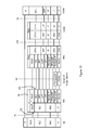
- Figure 7 illustrates the lu-CS control plane protocol architecture, showing the protocol stacks that are provided in the various network nodes, namely the UE 122, the FBS 118, nodes of the IP access network 114, the RNC 132 and the MSC 138.
- the WCDMA protocol structure is divided vertically into an Access Stratum (AS) and a Non-Access Stratum (NAS).
- the Access Stratum (AS) includes the Layer 1 (L1) protocol, the Media Access Control (MAC) protocol, the Radio Link Control (RLC) protocol, and the Radio Resource Control (RRC) protocol. It can be seen that these are terminated in the FBS 118, and transmitted over the IP access network 114 to the RNC 132, where they are terminated again, and interworked into the relevant protocols for transmission to the MSC 138.
- L1 Layer 1
- MAC Media Access Control
- RLC Radio Link Control
- RRC Radio Resource Control
- NAS Non-Access Stratum
- CC Call Control
- SS Supplementary Services
- SMS Short Message Service
- MM Mobility Management
- CM Connection Management
- the FBS 118 includes software 152 for terminating messages from the UE 122 in the protocols of the Non-Access Stratum that are intended for the MSC 138, and also includes software 154 for terminating messages from the MSC 138 in the protocols of the Non-Access Stratum that are intended for the UE 122.
- the FBS 118 also includes intelligence function (IF) software 156 for providing an interworking or relay function between the software 152 and the software 154.
- IF intelligence function
- Figure 8 illustrates the lu-CS control plane protocol architecture, showing the protocol stacks that are provided in the various network nodes, namely the UE 122, the FBS 118, nodes of the IP access network 114, the RNC 132 and the MSC 138.
- the FBS 118 includes software 162 for terminating messages from the UE 122 in the MAC and RLC protocols that are intended for the RNC 132, and also includes software 164 for terminating messages from the RNC 132 in the MAC and RLC protocols that are intended for the UE 122.
- the FBS 118 also includes intelligence function (IF) software 166 for providing an interworking or relay function between the software 162 and the software 164.
- IF intelligence function
- Figure 9 illustrates the packet switched domain control plane protocol stacks that are provided in the various network nodes, namely the UE 122, the FBS 118, nodes of the IP access network 114, the RNC 132 and the SGSN 140.
- the protocol structure is divided vertically into an Access Stratum (AS) and a Non-Access Stratum (NAS), and the Access Stratum (AS) includes the Layer 1 (L1) protocol, the Media Access Control (MAC) protocol, the Radio Link Control (RLC) protocol, and the Radio Resource Control (RRC) protocol. It can be seen that these are terminated in the FBS 118, and transmitted over the IP access network 114 to the RNC 132, where they are terminated again, and interworked into the relevant protocols for transmission to the SGSN 140.
- L1 Layer 1
- MAC Media Access Control
- RLC Radio Link Control
- RRC Radio Resource Control
- NAS Non-Access Stratum
- GMM GPRS Mobility Management
- SM Session Management
- SMS Short Message Service
- the FBS 118 includes software 172 for terminating messages from the UE 122 in the protocols of the Non-Access Stratum that are intended for the SGSN 140, and also includes software 174 for terminating messages from the SGSN 140 in the protocols of the Non-Access Stratum that are intended for the UE 122.
- the FBS 118 also includes intelligence function (IF) software 176 for providing an interworking or relay function between the software 172 and the software 174.
- IF intelligence function
- Figure 10 illustrates the lu-PS control plane protocol architecture, showing the protocol stacks that are provided in the various network nodes, namely the UE 122, the FBS 118, nodes of the IP access network 114, the RNC 132, the SGSN 140, and the GGSN (not shown in Figure 5 ), to which the SGSN 140 is connected.
- the FBS 118 includes software 182 for terminating messages from the UE 122 in the MAC, RLC and PDCP protocols that are intended for the RNC 132, and also includes software 184 for terminating messages from the RNC 132 in the MAC, RLC and PDCP protocols that are intended for the UE 122.
- the FBS 118 also includes intelligence function (IF) software 186 for providing an interworking or relay function between the software 182 and the software 184.
- IF intelligence function
- the FBS 18 may only interrogate protocol messages, without supporting call states (for example by receiving a release message that would take the state from answered to clear).
- protocol interrogation a decision can be made by the intelligence function software to change parts of the protocol message on the fly as it passes between the interfaces. No call states would be involved.
- Protocol interrogation is thus essentially an intelligent relaying function, which differs from a conventional relaying function in that, although the basestation merely passes the message on, it could potentially recognise the message, so that, if it was a release message, it could substitute another clearing cause within it.
- the FBS can, depending on the protocol message, on either side of the dual stack interface:
- Figure 12 illustrates a situation where the mapping functionality is used.
- This situation arises from the fact that the core network may for example allocate 10 Location Area Code (LAC) values (i.e. 1, 2, ..., 10) and 6000 Cell-IDs (i.e. the values 1 - 6000) to the femtocell network (that is, a total of 60,000 unique combinations of LAC value and Cell-ID).
- LAC Location Area Code
- Cell-IDs i.e. the values 1 - 6000
- the femtocell management system may for example prefer to maintain these 60,000, by using just 6 Cell-IDs (i.e. 1, 2, ..., 6), but 10,000 LAC values (i.e. the values 1-10,000).
- the LAC values 1, 2, ..., 10 in the core network domain are mapped to virtual LAC values 1-1000, 1001-2000, ..., 9001-10,000 in the femtocell network domain
- Cell-IDs 1-1000, 1001-2000, ..., 5001-6000 in the core network domain are mapped to virtual Cell-IDs 1, 2, ..., 6 in the femtocell network domain
- LAC values and Cell-IDs in messages sent from the core network to the mobile devices should be mapped to the appropriate virtual LAC values and Cell-IDs, and that, conversely, virtual LAC values and Cell-IDs in messages sent to the core network from the mobile devices should be mapped to the appropriate LAC values and Cell-IDs.
Abstract
Description
- This invention relates to a basestation for use in a cellular telecommunications system, and in particular to a basestation for use as a femtocell basestation. A traditional cellular telecommunications system includes a number of basestations, each serving a part of the total coverage area of the system, these areas being termed cells. Each basestation is connected to the core network of the system, typically over a wired connection. A user of a wireless communications device, located in one of these cells, is able to establish wireless communications with the relevant basestation, and the traffic is passed over the wired connection to the core network, where it can be routed as required.
- It has been suggested that, in order to increase the capacity of cellular telecommunications systems, femtocell basestations can additionally be provided. It has been suggested that a femtocell basestation could be obtained by a customer of the mobile network operator, and located within that customer's premises, which may for example be a home or a relatively small office. The femtocell basestation could then be connected to the core network of the cellular telecommunications system over the customer's existing broadband internet connection. In this case, a user of a suitably registered wireless communications device (which may for example be the customer's own conventional cellular wireless communications device), when it is located within the relatively small coverage area of the basestation (this area being termed a femtocell), is then able to establish wireless communications with the relevant femtocell basestation, and the traffic is passed over the broadband internet connection to the core network, where it can be routed as required.
- It is known that, in some cases, certain operations require relatively large numbers of messages to be transferred between the basestation and the core network, even in a conventional cellular communications system. In addition, in use of the femtocell basestation as described above, traffic that is intended to be uploaded from the registered wireless communications device to a device that is connected to the internet, or is intended to be downloaded to the registered wireless communications device from a device that is connected to the internet, is passed through the core network of the cellular communications system, placing an additional burden on the core network. According to a first aspect of the present invention, there is provided a basestation, having software that allows the basestation to terminate and/or interrogate messages sent from a mobile device that are intended for the network, and/or allows the basestation to terminate and/or interrogate messages sent from the network that are intended for the mobile device.
- This has the advantage that, in some situations, the number of messages transferred between the basestation and the network can be reduced. Further, the basestation operator can provide additional services to the user.
- For a better understanding of the present invention, and to show how it may be put into effect, reference will now be made, by way of example, to the accompanying drawings, in which:
-
Figure 1 is a block schematic diagram of a part of a cellular wireless communications network. -
Figure 2 shows the functional architecture of a part of the network illustrated inFigure 1 . -
Figure 3 is a protocol stack diagram, illustrating software operating on nodes in the part of the network shown inFigure 2 in an embodiment of the invention. -
Figure 4 is a further protocol stack diagram, illustrating software operating on nodes in the part of the network shown inFigure 2 in an embodiment of the invention. -
Figure 5 shows the functional architecture of a part of the network illustrated inFigure 1 , in an alternative embodiment. -
Figure 6 is a protocol stack diagram, illustrating software operating on nodes in the part of the network shown inFigure 5 in an embodiment of the invention. -
Figure 7 is a further protocol stack diagram, illustrating software operating on nodes in the part of the network shown inFigure 5 in an embodiment of the invention. -
Figure 8 is a further protocol stack diagram, illustrating software operating on nodes in the part of the network shown inFigure 5 in an embodiment of the invention. -
Figure 9 is a further protocol stack diagram, illustrating software operating on nodes in the part of the network shown inFigure 5 in an embodiment of the invention. -
Figure 10 is a further protocol stack diagram, illustrating software operating on nodes in the part of the network shown inFigure 5 in an embodiment of the invention. -
Figure 11 is a further protocol stack diagram, illustrating software operating on nodes in the part of the network shown inFigure 5 in an embodiment of the invention. -
Figure 12 illustrates a method in accordance with an aspect of the invention. -
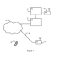
Figure 1 illustrates a part of a cellular wireless communications network in accordance with an aspect of the present invention. Specifically,Figure 1 shows a core network (CN) 10 and a radio network (RN) 12 of a cellular wireless communications network. These are generally conventional, and are illustrated and described herein only to the limited extent necessary for an understanding of the present invention. - Thus, the
core network 10 has connections into the Public Switched Telephone Network (PSTN) (not shown) and into a packet data network, for example theinternet 14. Theradio network 12 may include, for example, a GSM radio network and/or a UMTS radio network, which are then generally conventional. As shown inFigure 1 , theradio network 12 has a basestation (BS) 16 connected thereto. As will be recognized by the person skilled in the art, atypical radio network 12 will have many such basestations connected thereto. These basestations provide coverage over respective geographic areas, or cells, such that a service is available to subscribers. Often, there is a group of basestations that together provide coverage to the whole of the intended service area, while other basestations provide additional coverage to smaller areas within that intended service area, in particular to smaller areas where there is expected to be more demand for the service. The cells served by the basestations of the first group are then referred to as macrocells, while the smaller areas served by the additional basestations are referred to as microcells. -
Figure 1 also shows anadditional basestation 18 that can be used to provide coverage over a very small area, for example within a single home or office building. This is referred to as a femtocell basestation (FBS). The femtocellbasestation 18 is connected into the mobile network operator'score network 10 over theinternet 14, by means of the customer's existingbroadband internet connection 20. Thus, a user of a conventionalmobile phone 22 can establish a connection through the femtocellbasestation 18 with another device, in the same way that any other mobile phone can establish a connection through one of the other basestations of the mobile network operator's network, such as thebasestation 16. - As mentioned above, the macrocell basestations provide coverage to the whole of the intended service area including the location of the femtocell
basestation 18 and the location of themobile phone 22 while it is in the coverage area of thefemtocell basestation 18. However, the network is configured such that, when a mobile device that is allowed to be registered with thefemtocell basestation 18 is within the coverage area of thefemtocell basestation 18, then it will preferentially establish a connection with thefemtocell basestation 18 rather than with themacrolayer basestation 16. -
Figure 2 shows the functional architecture of a part of the network illustrated inFigure 1 . Specifically, the mobile phone, or user equipment (UE), 22 is shown, having a connection into the femtocell basestation (FBS) 18 over a Uu radio interface. Other devices can also be used to connect to theFBS 18, such as a POTS orSIP phone 26, which can connect over a POTS or SIP interface, as appropriate, or aPC 28, which can for example connect over IP, or over USB, or over WFi, or over an Ethernet connection. - The FBS 18 includes a USIM 30, which can take the form of a SIM card as is conventional, or can contain the required data in any removable or non-removable module. The USIM 30 allows the FBS 18 to identify itself to the mobile network operator's core network as if it were itself a mobile device, and provides suitable authorization and encryption functionality.
- The FBS 18 has a connection over the generic
IP access network 14 to theinternet 31. In this case, the FBS 18 uses the UMA (Unlicensed Mobile Access) protocol for backhaul, and has a Up' interface over the genericIP access network 14 to a 3G L-GANC (Generic Access Network Controller) 32. - The FBS 18 is also able to establish a Zz interface over the generic
IP access network 14, through asecurity gateway 34 in the Generic Access Network Controller 32 to a management system (MS) 36. Themanagement system 36 is operated by the mobile network operator, and supports the operation of the femtocell basestations, such as the FBS 18, within the network. - The 3G L-GANC (Generic Access Network Controller) 32 is then connected to the
core network 10 of the mobile network operator. The network may be the Home Public Land Mobile Network (HPLMN) or the Visited Public Land Mobile Network (VPLMN) defined in the 3G specifications. In this illustrated case, the network includes both a Mobile Switching Center (MSC) 38 for circuit switched data, to which theGANC 32 may establish a lu-CS interface, and a Serving GPRS Support Node (SGSN) 40 for packet switched data, to which theGANC 32 may establish a lu-PS interface. -
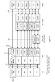
Figure 3 illustrates the circuit switched domain control plane protocol stacks that are provided in the various network nodes, namely the UE 22, theFBS 18, nodes of theIP access network 14, the 3G L-GANC 32 and theMSC 38. - As is well known, the WCDMA protocol structure is divided vertically into an Access Stratum (AS) and a Non-Access Stratum (NAS). The Access Stratum (AS) includes the Layer 1 (L1) protocol, the Media Access Control (MAC) protocol, the Radio Link Control (RLC) protocol, and the Radio Resource Control (RRC) protocol. It can be seen that these are terminated in the
FBS 18, and interworked into the relevant UMA protocol layers for transmission over theIP access network 14 to the GANC 32, where they are terminated again, and interworked into the relevant protocols for transmission to theMSC 38. - By contrast, the UE 22 and the MSC 38 would be able to communicate directly with each other using the Non-Access Stratum (NAS) protocols, which may include the Call Control (CC) protocol, the Supplementary Services (SS) protocol, the Short Message Service (SMS) protocol, the Mobility Management (MM) protocol, and the Connection Management (CM) protocol, for example.
- However, in accordance with an aspect of the present invention, the FBS 18 includes
software 42 for terminating messages from the UE 22 in the protocols of the Non-Access Stratum that are intended for the MSC 38, and also includessoftware 44 for terminating messages from the MSC 38 in the protocols of the Non-Access Stratum that are intended for the UE 22. The FBS 18 also includes intelligence function (IF)software 46 for providing an interworking or relay function between thesoftware 42 and thesoftware 44. - Thus, in this embodiment of the invention, and others, the software in the FBS 18 includes software for interworking between the wireless communications over the Uu interface on the one hand and the communications using the UMA protocol with the 3G L-GANC on the other hand.
- However, the software in the FBS 18 also includes back-to-back NAS software stacks. These stacks allow messages in the NAS protocol layers, that have been sent from the UE and would conventionally be expected to be received in the MSC, to be terminated in the FBS 18. Messages can then be recreated for onward transmission to the MSC, either in the same form or with modification of one or more parameter value, or the messages can instead be handled in a different way, for example by transmitting a message over the internet without passing through the MSC. Similarly, the software in the
FBS 18 also allows messages in the NAS protocol layers, that have been sent from the MSC and would conventionally be expected to be received in the UE, to be terminated in theFBS 18. Messages can then be recreated for onward transmission to the UE, either in the same form or with modification of one or more parameter value, or the messages can instead be handled in a different way. - The operation of the
software FBS 18 will be described in more detail below. -
Figure 4 illustrates the packet switched domain control plane protocol stacks that are provided in the various network nodes, namely theUE 22, theFBS 18, nodes of theIP access network 14, the 3G L-GANC 32 and theSGSN 40. - As before, the protocol structure is divided vertically into an Access Stratum (AS) and a Non-Access Stratum (NAS), and the Access Stratum (AS) includes the Layer 1 (L1) protocol, the Media Access Control (MAC) protocol, the Radio Link Control (RLC) protocol, and the Radio Resource Control (RRC) protocol. It can be seen that these are terminated in the
FBS 18, and interworked into the relevant UMA protocol layers for transmission over theIP access network 14 to theGANC 32, where they are terminated again, and interworked into the relevant protocols for transmission to theSGSN 40. - By contrast, the
UE 22 and theSGSN 40 would be able to communicate directly with each other using the Non-Access Stratum (NAS) protocols, which may include the GPRS Mobility Management (GMM) protocol, the Session Management (SM) protocol, and the Short Message Service (SMS) protocol, for example. - However, in accordance with an aspect of the present invention, the
FBS 18 includessoftware 48 for terminating messages from theUE 22 in the protocols of the Non-Access Stratum that are intended for theSGSN 40, and also includessoftware 50 for terminating messages from theSGSN 40 in the protocols of the Non-Access Stratum that are intended for theUE 22. TheFBS 18 also includes intelligence function (IF)software 52 for providing an interworking or relay function between thesoftware 48 and thesoftware 50. - Thus, in these embodiments, the
FBS 18 supports the relevant protocols to make theUE 22 believe that it is working into a 3G UMTS network. Towards the network, theFBS 18 supports the UMA protocols to make theGANC 32 believe that it is communicating with a UMA client and to make the MSC 38 (or SGSN 40) believe that it is communicating with a 3G UE. Theintelligence function intelligence function intelligence function -
Figure 5 shows the functional architecture of a part of the network illustrated inFigure 1 , in an alternative embodiment. Specifically, a mobile phone, or user equipment (UE), 122 is shown, having a connection into the femtocell basestation (FBS) 118 over a Uu radio interface. Other devices can also be used to connect to theFBS 118, such as a POTS orSIP phone 126, which can connect over a POTS or SIP interface, as appropriate, or aPC 128, which can connect over IP, or over USB, or over an Ethernet connection. - The
FBS 118 includes aUSIM 130, which can take the form of a SIM card as is conventional, or can contain the required data in any removable or non-removable module. TheUSIM 130 allows theFBS 118 to identify itself to the mobile network operator's core network as if it were itself a mobile device, and provides suitable authorization and encryption functionality. - The
FBS 118 has a connection over the genericIP access network 114 to theinternet 131. - In this case, the
FBS 118 has a slightly modified lub interface, referred to as an lub' interface, a 3G RNC (Radio Network Controller) 132. - The
FBS 118 is also able to establish a Zz interface over the genericIP access network 114, through asecurity gateway 134 in theRadio Network Controller 132 to a management system (MS) 136. Themanagement system 136 is operated by the mobile network operator, and supports the operation of the femtocell basestations, such as theFBS 118, within the network. - The
Radio Network Controller 132 is then connected to thecore network 110 of the mobile network operator. The network may be the Home Public Land Mobile Network (HPLMN) or the Visited Public Land Mobile Network (VPLMN) defined in the 3G specifications. In this illustrated case, the network includes both a Mobile Switching Center (MSC) 138 for circuit switched data, to which theRNC 132 may establish a lu-CS interface, and a Serving GPRS Support Node (SGSN) 140 for packet switched data, to which theRNC 32 may establish a lu-PS interface. -
Figure 6 illustrates the lub control plane protocol architecture, showing the protocol stacks that are provided in theFBS 118, nodes of theIP access network 114, and theRNC 132. Specifically, theFBS 118 includessoftware 142 for terminating Radio Resource Control (RRC) messages from theUE 122 that are intended for theRNC 132, and also includessoftware 144 for terminating RRC messages from theRNC 132 that are intended for theUE 122. TheFBS 118 also includes intelligence function (IF)software 146 for providing an interworking or relay function between thesoftware 142 and thesoftware 144. -
Figure 7 illustrates the lu-CS control plane protocol architecture, showing the protocol stacks that are provided in the various network nodes, namely theUE 122, theFBS 118, nodes of theIP access network 114, theRNC 132 and theMSC 138. - As discussed above, the WCDMA protocol structure is divided vertically into an Access Stratum (AS) and a Non-Access Stratum (NAS). The Access Stratum (AS) includes the Layer 1 (L1) protocol, the Media Access Control (MAC) protocol, the Radio Link Control (RLC) protocol, and the Radio Resource Control (RRC) protocol. It can be seen that these are terminated in the
FBS 118, and transmitted over theIP access network 114 to theRNC 132, where they are terminated again, and interworked into the relevant protocols for transmission to theMSC 138. - By contrast, the
UE 122 and theMSC 138 would be able to communicate directly with each other using the Non-Access Stratum (NAS) protocols, which may include the Call Control (CC) protocol, the Supplementary Services (SS) protocol, the Short Message Service (SMS) protocol, the Mobility Management (MM) protocol, and the Connection Management (CM) protocol, for example. - However, in accordance with an aspect of the present invention, the
FBS 118 includessoftware 152 for terminating messages from theUE 122 in the protocols of the Non-Access Stratum that are intended for theMSC 138, and also includessoftware 154 for terminating messages from theMSC 138 in the protocols of the Non-Access Stratum that are intended for theUE 122. TheFBS 118 also includes intelligence function (IF)software 156 for providing an interworking or relay function between thesoftware 152 and thesoftware 154. - The operation of the
software FBS 118 will be described in more detail below. -
Figure 8 illustrates the lu-CS control plane protocol architecture, showing the protocol stacks that are provided in the various network nodes, namely theUE 122, theFBS 118, nodes of theIP access network 114, theRNC 132 and theMSC 138. - The
UE 122 and theRNC 132 would be able to communicate directly with each other using the Media Access Control (MAC) protocol and the Radio Link Control (RLC) protocol. However, in accordance with an aspect of the present invention, theFBS 118 includessoftware 162 for terminating messages from theUE 122 in the MAC and RLC protocols that are intended for theRNC 132, and also includessoftware 164 for terminating messages from theRNC 132 in the MAC and RLC protocols that are intended for theUE 122. TheFBS 118 also includes intelligence function (IF)software 166 for providing an interworking or relay function between thesoftware 162 and thesoftware 164. -
Figure 9 illustrates the packet switched domain control plane protocol stacks that are provided in the various network nodes, namely theUE 122, theFBS 118, nodes of theIP access network 114, theRNC 132 and theSGSN 140. - As before, the protocol structure is divided vertically into an Access Stratum (AS) and a Non-Access Stratum (NAS), and the Access Stratum (AS) includes the Layer 1 (L1) protocol, the Media Access Control (MAC) protocol, the Radio Link Control (RLC) protocol, and the Radio Resource Control (RRC) protocol. It can be seen that these are terminated in the
FBS 118, and transmitted over theIP access network 114 to theRNC 132, where they are terminated again, and interworked into the relevant protocols for transmission to theSGSN 140. - By contrast, the
UE 122 and theSGSN 140 would be able to communicate directly with each other using the Non-Access Stratum (NAS) protocols, which may include the GPRS Mobility Management (GMM) protocol, the Session Management (SM) protocol, and the Short Message Service (SMS) protocol, for example. - However, in accordance with an aspect of the present invention, the
FBS 118 includessoftware 172 for terminating messages from theUE 122 in the protocols of the Non-Access Stratum that are intended for theSGSN 140, and also includessoftware 174 for terminating messages from theSGSN 140 in the protocols of the Non-Access Stratum that are intended for theUE 122. TheFBS 118 also includes intelligence function (IF)software 176 for providing an interworking or relay function between thesoftware 172 and thesoftware 174. -
Figure 10 illustrates the lu-PS control plane protocol architecture, showing the protocol stacks that are provided in the various network nodes, namely theUE 122, theFBS 118, nodes of theIP access network 114, theRNC 132, theSGSN 140, and the GGSN (not shown inFigure 5 ), to which theSGSN 140 is connected. - The
UE 122 and theRNC 132 would be able to communicate directly with each other using the Media Access Control (MAC) protocol, the Radio Link Control (RLC) protocol, and the Packet Data Convergence Protocol (PDCP). However, in accordance with an aspect of the present invention, theFBS 118 includessoftware 182 for terminating messages from theUE 122 in the MAC, RLC and PDCP protocols that are intended for theRNC 132, and also includessoftware 184 for terminating messages from theRNC 132 in the MAC, RLC and PDCP protocols that are intended for theUE 122. TheFBS 118 also includes intelligence function (IF)software 186 for providing an interworking or relay function between thesoftware 182 and thesoftware 184. - There are thus described various embodiments of the invention, in which the topmost protocol layers are terminated in the femtocell basestation. However, in other embodiments of the invention, less of the protocols are terminated in the femtocell basestation, while still allowing the basestation to perform useful functions.
- For an example of this,
Figure 11 is similar toFigure 7 , but illustrates an alternative form of the lu-CS control plane protocol architecture, showing the protocol stacks that are provided in the various network nodes, namely theUE 122, theFBS 118, nodes of theIP access network 114, theRNC 132 and theMSC 138. - As discussed above, the WCDMA protocol structure is divided vertically into an Access Stratum (AS) and a Non-Access Stratum (NAS). The Access Stratum (AS) includes the Layer 1 (L1) protocol, the Media Access Control (MAC) protocol, the Radio Link Control (RLC) protocol, and the Radio Resource Control (RRC) protocol. It can be seen that these are terminated in the
FBS 118, and transmitted over theIP access network 114 to theRNC 132, where they are terminated again, and interworked into the relevant protocols for transmission to theMSC 138. - In addition, the
UE 122 and theMSC 138 communicate directly with each other using some of the Non-Access Stratum (NAS) protocols, including the Call Control (CC) protocol, the Supplementary Services (SS) protocol, the Short Message Service (SMS) protocol, and parts of the Mobility Management (MM) protocol. - However, in accordance with an aspect of the present invention, the
FBS 118 includessoftware 192 for terminating messages from theUE 122 in a part of the Mobility Management (MM) protocol that are intended for theMSC 138, and also includessoftware 194 for terminating messages from theMSC 138 in that part of the Mobility Management (MM) protocol that are intended for theUE 122. TheFBS 118 also includes intelligence function (IF)software 196 for providing an interworking or relay function between thesoftware 192 and thesoftware 194. - Terminating these messages in the part of the Mobility Management (MM) protocol allows the
FBS 118 to obtain the IMSI of theUE 122. For example, this allows the FBS to determine which UE is attempting to register with theFBS 118, so that registration requests by non-allowed UEs can be terminated without core network involvement. Also, this allows for data from theUE 122 to be transferred over theinternet 131 rather than over the core network, if this is more convenient. - Thus, in these embodiments, the
FBS 118 supports the relevant protocols to make theUE 122 believe that it is working into a 3G UMTS network. Towards the network, theFBS 118 supports the relevant protocols to make theRNC 132 and the MSC 138 (or SGSN 140) believe that they are communicating with a 3G UE. Theintelligence function - It will be apparent that the same principle can be applied in other situations. For example, the femtocell basestation can be connected into a 2G core network (for example based on GPRS), rather than a 3G core network, as described here. In this case, the software in the femtocell basestation also provides interworking between a 2G core network and a 3G air-interface.
- The operation of the intelligence function (IF) software and the illustrated protocol stacks in the
FBS 18 will be described in more detail below. In the following description, reference will be made to the embodiment ofFigure 3 above, and thus reference will be made to theUE 22, theFBS 18, and itssoftware - As described above,
software 42 is provided in theFBS 18 for terminating messages from theUE 22 in the protocols of the Non-Access Stratum that are intended for the relevant node of thecore network 10. A signalling connection is therefore established between theUE 22 and theFBS 18. This allows theUE 22 to communicate through theFBS 18 without needing to adapt its transmissions in any way, compared to the situation in which it communicates through any other basestation. - Similarly,
software 44 is provided in theFBS 18 for terminating messages from the relevant node of thecore network 10 in the protocols of the Non-Access Stratum that are intended for theUE 22. A signalling connection is therefore established between the node of thecore network 10 and theFBS 18. This allows the core network node to communicate through theFBS 18 without needing to adapt its transmissions in any way, compared to the situation in which it communicates with a UE through any other basestation. - As described above, the
FBS 18 also includessoftware 46 for providing an interworking or relay function between thesoftware 42 and thesoftware 44. This software can determine how to handle the received messages, terminated by thesoftware 42 or thesoftware 44, based on the message type and/or the message content. - For example, the
software 46 can be such that some messages are effectively simply retransmitted in the same form. - In other cases, the
software 46 can be such that certain messages need not be retransmitted. For example, wireless communication protocols typically allow the UE to request retransmission of messages that it was not able to receive correctly. In a conventional network, such messages are transmitted from the UE to the core network node and cause the message to be retransmitted from the core network node, and therefore use core network resources. In this case, such messages can be terminated by thesoftware 42 and read by thesoftware 46, and the retransmission can take place from theFBS 18, without requiring any traffic to be sent to the core network and without any use of core network resources. - As another example, use of the
software 46 enables Layer 3 (and above) control in theFBS 18 of all CS and PS calls. - As another example, use of the
software 46 enables local registration and call attempts to be accepted or rejected locally without having to go over to the core network. That is, local registration and call attempt messages can be terminated by thesoftware 42, and read by thesoftware 46, which can also make a decision without requiring core network involvement. - As another example, use of the
software 46 enables local services without core network involvement. - As another example, use of the
software 46 enables local internet offload. That is, a message sent from theUE 22, and intended for a recipient accessible over the internet, can be terminated by thesoftware 42 and read by thesoftware 46. Thesoftware 46 can then decide to route this message over theinternet 30 directly, as illustrated inFigure 2 , without requiring core network involvement. - More generally, the
software 46 may allow theFBS 18 to operate in a termination mode, in which it may terminate any layer of the protocol on either side of the double stack interface, that is, in thesoftware 42 or thesoftware 44, as appropriate. - To explain this, it needs to be understood that each layer of the protocol stack has messages associated with it. These messages are only understood within the layer. Usually, the messages are point to point, which requires the protocol to be terminated in the receiving node. Termination means for instance that the node has call states, e.g. a null state waiting for an incoming SETUP message. Once received, the node moves to a call present state. This state can notice that the traffic channel requested in the setup message is not available. If this is the case, it sends a RELEASE COMPLETE message and enters the null state. Otherwise it sends a CALL PROCEEDING message to the network indicating the call has been accepted. Thus, when a protocol is terminated it can interact with its peer layer. Also, when the protocol is terminated, it can then interwork with other protocols. For example, a node may be provided with 3G UE CS signalling on one interface towards one network entity, with SIP on another interface towards a different network entity. The CS protocol uses information elements IE whilst the other is text based.
- In embodiments of the invention, the
basestation 18 is provided with software that allows it to terminate various protocol layers, as illustrated above, even where the sending node intends the messages to be sent transparently through the basestation (for example from the mobile device to the network, or from the network to the mobile device). Terminating the protocol provides more scope to add features and services. - The basestation may then:
- support relevant call states;
- relay the protocol messages;
- map messages to the same protocol messages;
- map (interwork) protocol messages to other protocols (e.g CS-SIP);
- subsume/discard protocol messages (location updates);
- convert information (e.g. converting between the cell-id and the geographical coordinates of the cell);
- provide local services (without passing on the messages, for example, to the core nefinork);
- make decisions based on the protocol message;
- initiate messages without instruction from the core network;
- map between different codecs (eg AMR - G.711 PCM).
- Additionally, the
FBS 18 may only interrogate protocol messages, without supporting call states (for example by receiving a release message that would take the state from answered to clear). In the case of protocol interrogation, a decision can be made by the intelligence function software to change parts of the protocol message on the fly as it passes between the interfaces. No call states would be involved. Protocol interrogation is thus essentially an intelligent relaying function, which differs from a conventional relaying function in that, although the basestation merely passes the message on, it could potentially recognise the message, so that, if it was a release message, it could substitute another clearing cause within it. - In the interrogation mode the FBS can, depending on the protocol message, on either side of the dual stack interface:
- relay the protocol messages;
- map messages to the same protocol messages;
- subsume/discard protocol messages (such as location updates);
- alter information in a message (e.g. between cell-id and geographical coordinates).
-
Figure 12 illustrates a situation where the mapping functionality is used. This situation arises from the fact that the core network may for example allocate 10 Location Area Code (LAC) values (i.e. 1, 2, ..., 10) and 6000 Cell-IDs (i.e. the values 1 - 6000) to the femtocell network (that is, a total of 60,000 unique combinations of LAC value and Cell-ID). However, to provide additional flexibility in its resource allocation, the femtocell management system may for example prefer to maintain these 60,000, by using just 6 Cell-IDs (i.e. 1, 2, ..., 6), but 10,000 LAC values (i.e. the values 1-10,000). - This can be achieved by mapping the LAC values and Cell-IDs in the core network domain to virtual LAC values and Cell-IDs in the femtocell network domain. As shown in
Figure 12 , the LAC values 1, 2, ..., 10 in the core network domain are mapped to virtual LAC values 1-1000, 1001-2000, ..., 9001-10,000 in the femtocell network domain, while Cell-IDs 1-1000, 1001-2000, ..., 5001-6000 in the core network domain are mapped to virtual Cell-IDs - For this scheme to work, it is necessary that LAC values and Cell-IDs in messages sent from the core network to the mobile devices should be mapped to the appropriate virtual LAC values and Cell-IDs, and that, conversely, virtual LAC values and Cell-IDs in messages sent to the core network from the mobile devices should be mapped to the appropriate LAC values and Cell-IDs.
- This is achieved in the intelligence function software by termination of the relevant messages, removal of the values from the sending domain, and insertion of the values from the receiving domain, followed by retransmitting the messages in the appropriate protocol.
- This therefore allows the messages to be sent, and correctly received, without the sending entity needing to know that the message has been terminated in the basestation.
- Other aspects of the invention are defined in the following numbered paragraphs:
- 1. A basestation, for use in a cellular mobile communications system, the basestation having a wireless interface for connection with a mobile communications device, and having an interface for connection with a network of said cellular mobile communications system, wherein, in said cellular mobile communications system, the mobile communications device sends messages intended for the network and the network sends messages intended for the mobile communications device according to a standardized communications protocol, wherein the basestation comprises:
- software for terminating said messages sent from the mobile communications device intended for the network, and for sending messages according to the standardized communications protocol to the network in response to at least some of said terminated messages; and
- software for terminating said messages sent from the network intended for the mobile communications device, and for sending messages according to the standardized communications protocol to the network in response to at least some of said terminated messages.
- 2. A basestation as defined in numbered
paragraph 1, comprising:- software for terminating said messages sent from the mobile communications device intended for the network in accordance with a non-access stratum of the standardized communications protocol; and
- software for terminating said messages sent from the network intended for the mobile communications device in accordance with a non-access stratum of the standardized communications protocol.
- 3. A basestation, for use in a mobile communications system, the basestation comprising back-to-back software stacks, for terminating protocol messages from a UE and recreating messages for onward transmission to the mobile network, and for terminating protocol messages from the mobile network and recreating messages for onward transmission to the UE.
- 4. A basestation as defined in numbered paragraph 3, wherein the software is adapted to recreate messages either in the same form or with modification of one or more parameter value.
- 5. A basestation as defined in numbered paragraph 3 or 4, wherein the back-to-back software stacks comprises NAS software layers.
- 6. A basestation, for use in a mobile communications system, the basestation comprising back-to-back software stacks, for interrogating protocol messages sent from a UE and intended for onward transmission to the mobile network, and for interrogating protocol messages sent from the mobile network and intended for onward transmission to the UE.
- 7. A basestation as defined in numbered
paragraph 6, wherein the software is adapted to modify said protocol messages before said onward transmission. - 8. A basestation as defined in numbered
paragraph 6 or 7, wherein the back-to-back software stacks comprises NAS software layers.
Claims (8)
- A method of handling a circuit-switched or packet-switched call, the method comprising:receiving a message from a user equipment device in a protocol of the Non-Access Stratum, intended for a Mobile Switching Centre or a SGSN or GGSN in a core network of a telecommunications network;terminating the message in the protocol of the Non-Access Stratum; andperforming local call control based on the message.
- A method as claimed in claim 1, wherein the step of performing local call control comprises performing Layer 3 control.
- A method as claimed in claim 1 or claim 2, wherein the call is a circuit-switched call intended for the Mobile Switching Centre in the core network of the telecommunications network and the message is a message in the Call Control protocol of the Non-Access Stratum.
- A method as claimed in claim 1 or claim 2, wherein the call is a packet-switched call intended for the SGSN or GGSN in the core network of a telecommunications network and the message is a message in the Session Management protocol of the Non-Access Stratum.
- A method as claimed in claim 1, 2, 3 or 4, comprising performing the method in a femtocell basestation.
- A method as claimed in claim 5, comprising:having terminated the message in the protocol of the Non-Access Stratum, obtaining an IMSI of the user equipment device;determining whether the user equipment device is allowed to register with the femtocell basestation; andif the user equipment device is not allowed to register with the femtocell basestation, terminating a registration attempt.
- A computer readable product, comprising software for performing a method as claimed in any of claims 1 to 6.
- A femtocell basestation, configured to perform a method as claimed in any of claims 1-4 or 6.
Applications Claiming Priority (3)
| Application Number | Priority Date | Filing Date | Title |
|---|---|---|---|
| GB0703603A GB2447442A (en) | 2007-02-23 | 2007-02-23 | Base station for cellular communication system |
| EP08702013.7A EP2123100B1 (en) | 2007-02-23 | 2008-02-01 | Basestation for cellular communications system |
| PCT/GB2008/000346 WO2008102099A1 (en) | 2007-02-23 | 2008-02-01 | Basestation for cellular communications system |
Related Parent Applications (2)
| Application Number | Title | Priority Date | Filing Date |
|---|---|---|---|
| EP08702013.7A Division EP2123100B1 (en) | 2007-02-23 | 2008-02-01 | Basestation for cellular communications system |
| EP08702013.7 Division | 2008-02-01 |
Publications (3)
| Publication Number | Publication Date |
|---|---|
| EP2482610A2 true EP2482610A2 (en) | 2012-08-01 |
| EP2482610A3 EP2482610A3 (en) | 2017-11-08 |
| EP2482610B1 EP2482610B1 (en) | 2020-12-09 |
Family
ID=37945659
Family Applications (3)
| Application Number | Title | Priority Date | Filing Date |
|---|---|---|---|
| EP12161284.0A Active EP2482610B1 (en) | 2007-02-23 | 2008-02-01 | Basestation for cellular communications system |
| EP08702013.7A Active EP2123100B1 (en) | 2007-02-23 | 2008-02-01 | Basestation for cellular communications system |
| EP12161245.1A Active EP2482580B1 (en) | 2007-02-23 | 2008-02-01 | Basestation for cellular communications system |
Family Applications After (2)
| Application Number | Title | Priority Date | Filing Date |
|---|---|---|---|
| EP08702013.7A Active EP2123100B1 (en) | 2007-02-23 | 2008-02-01 | Basestation for cellular communications system |
| EP12161245.1A Active EP2482580B1 (en) | 2007-02-23 | 2008-02-01 | Basestation for cellular communications system |
Country Status (7)
| Country | Link |
|---|---|
| US (2) | US8483760B2 (en) |
| EP (3) | EP2482610B1 (en) |
| JP (2) | JP5544171B2 (en) |
| CN (1) | CN101690274B (en) |
| ES (1) | ES2424974T3 (en) |
| GB (3) | GB2447442A (en) |
| WO (1) | WO2008102099A1 (en) |
Families Citing this family (19)
| Publication number | Priority date | Publication date | Assignee | Title |
|---|---|---|---|---|
| DE202005021930U1 (en) * | 2005-08-01 | 2011-08-08 | Corning Cable Systems Llc | Fiber optic decoupling cables and pre-connected assemblies with toning parts |
| GB2447442A (en) | 2007-02-23 | 2008-09-17 | Ubiquisys Ltd | Base station for cellular communication system |
| EP2273846A1 (en) * | 2008-04-22 | 2011-01-12 | Fujitsu Limited | Communication device and communication method |
| RU2507715C2 (en) * | 2008-06-16 | 2014-02-20 | Самсунг Электроникс Ко., Лтд. | Method and system for controlling transmission in radio access networks |
| US20100159895A1 (en) * | 2008-07-30 | 2010-06-24 | Mavenir Systems, Inc. | Providing enhanced edge services to devices in femtozones |
| US8032164B2 (en) * | 2008-09-22 | 2011-10-04 | Interdigital Patent Holdings, Inc. | Method and apparatus for communicating short message service and supplementary services messages |
| JP5327437B2 (en) * | 2008-09-26 | 2013-10-30 | 住友電気工業株式会社 | Communication control device, communication system, and small base station |
| JP2010093329A (en) * | 2008-10-03 | 2010-04-22 | Sumitomo Electric Ind Ltd | Communication control device |
| JP2010136166A (en) * | 2008-12-05 | 2010-06-17 | Sumitomo Electric Ind Ltd | Compact base station |
| JP2010136165A (en) * | 2008-12-05 | 2010-06-17 | Sumitomo Electric Ind Ltd | Compact base station |
| CN101772130A (en) * | 2009-01-07 | 2010-07-07 | 中兴通讯股份有限公司 | Auxiliary detection signaling sending method |
| US8275400B2 (en) * | 2009-06-15 | 2012-09-25 | Argela-Usa | Method and system for SMS based ticket number service over femtocell access point |
| US20110034182A1 (en) * | 2009-08-05 | 2011-02-10 | Oto Technologies, Llc | Geographic messaging using location-identified access points |
| EP2482567B1 (en) | 2009-09-27 | 2016-05-04 | ZTE Corporation | Method and apparatus for status transition |
| GB2474504B (en) | 2009-10-19 | 2015-12-02 | Ubiquisys Ltd | Wireless access point |
| US20140066018A1 (en) * | 2012-09-06 | 2014-03-06 | Telecommunication Systems, Inc. | Location Based Privacy for Proximity Services |
| WO2018035177A2 (en) | 2016-08-15 | 2018-02-22 | Parallel Wireless, Inc. | Convergence proxy for core network virtualization |
| US10531356B2 (en) | 2016-08-15 | 2020-01-07 | Parallel Wireless, Inc. | VoIP and native carrier call integration |
| CN107566476B (en) * | 2017-08-25 | 2020-03-03 | 中国联合网络通信集团有限公司 | Access method, SDN controller, forwarding equipment and user access system |
Family Cites Families (71)
| Publication number | Priority date | Publication date | Assignee | Title |
|---|---|---|---|---|
| JP2653000B2 (en) | 1991-04-24 | 1997-09-10 | 日本電気株式会社 | Mobile wireless communication system |
| US5915219A (en) | 1992-09-10 | 1999-06-22 | Nokia Telecommunications Oy | Cellular radio network divided into a primary network covering a selected operating area and at least one subsystem covering possibly overlapping area, with possibility of handoff and registration between primary network and subsystem |
| JP3461831B2 (en) | 1993-07-16 | 2003-10-27 | エリクソン インコーポレイテッド | Method and apparatus for controlling transceiver operation in a wireless communication system |
| SE514018C2 (en) | 1993-09-23 | 2000-12-11 | Ericsson Telefon Ab L M | Method of registration in a cellular cellular radio system |
| DE4442410A1 (en) | 1994-11-29 | 1996-05-30 | Alcatel Mobile Comm Deutsch | Radio system for a closed user group |
| FI103556B (en) | 1996-06-26 | 1999-07-15 | Nokia Telecommunications Oy | Procedure for position management and searching in a cellular row io system |
| DE19633925C2 (en) | 1996-08-22 | 2000-11-23 | Siemens Ag | Mobile radio system and base transceiver station with integrated telephone device |
| US5794157A (en) | 1996-08-28 | 1998-08-11 | Telefonaktiebolaget Lm Ericsson | Method and system for autonomously allocating transmit power levels for communication between a cellular terminal and a telephone base station |
| CN1100469C (en) | 1996-10-23 | 2003-01-29 | 西门子公司 | Location dependent mobile communication terminal log on method |
| JP3585333B2 (en) | 1996-12-26 | 2004-11-04 | 松下電器産業株式会社 | CDMA base station device |
| JPH10271223A (en) | 1997-02-18 | 1998-10-09 | Lucent Technol Inc | Access supply device/method for web information |
| US6101388A (en) | 1997-07-24 | 2000-08-08 | Intel Corporation | Method for reducing registration traffic in a GSM system |
| US6414952B2 (en) * | 1997-08-28 | 2002-07-02 | Broadcom Homenetworking, Inc. | Virtual gateway system and method |
| FR2771585B1 (en) | 1997-11-24 | 2000-01-28 | Nortel Matra Cellular | PRIVATE BASE STATION FOR MOBILE RADIOTELEPHONE |
| US7596378B1 (en) | 1999-09-30 | 2009-09-29 | Qualcomm Incorporated | Idle mode handling in a hybrid GSM/CDMA network |
| US6842462B1 (en) * | 1998-12-18 | 2005-01-11 | Lucent Technologies Inc. | Wireless access of packet based networks |
| SE519347C2 (en) | 1999-02-18 | 2003-02-18 | Ericsson Telefon Ab L M | Procedure and node for updating information of a subscriber belonging to a localized service area |
| EP1032236A1 (en) | 1999-02-24 | 2000-08-30 | ICO Services Ltd. | Improved congestion control using access classes |
| US7003297B2 (en) | 1999-04-06 | 2006-02-21 | Telefonaktiebolaget Lm Ericsson (Publ) | Partial support of mobility between radio access networks |
| GB2355885A (en) | 1999-07-30 | 2001-05-02 | Nokia Telecommunications Oy | Network access control |
| EP1238551B1 (en) | 1999-12-01 | 2006-02-08 | Robert Bosch Gmbh | Method for allocating transmission channels in a telecommunications network and subscriber station |
| FI19992593A (en) * | 1999-12-02 | 2001-06-03 | Nokia Networks Oy | Call routing in a telecommunications system |
| US6907017B2 (en) | 2000-05-22 | 2005-06-14 | The Regents Of The University Of California | Mobility management in wireless internet protocol networks |
| ITTS20000003A1 (en) | 2000-05-31 | 2001-12-01 | Telit Networks Spa | SELF PLANNER: AUTOMATIC FREQUENTIAL PLANNING FOR RADIO MOBILE SYSTEMS |
| US6901061B1 (en) | 2000-09-05 | 2005-05-31 | Cisco Technology, Inc. | Handoff control in an enterprise division multiple access wireless system |
| EP1207708B1 (en) | 2000-11-17 | 2004-10-27 | Telefonaktiebolaget LM Ericsson (publ) | A mobile communication network |
| US20050239453A1 (en) * | 2000-11-22 | 2005-10-27 | Vikberg Jari T | Mobile communication network |
| US7039027B2 (en) | 2000-12-28 | 2006-05-02 | Symbol Technologies, Inc. | Automatic and seamless vertical roaming between wireless local area network (WLAN) and wireless wide area network (WWAN) while maintaining an active voice or streaming data connection: systems, methods and program products |
| JP2002218528A (en) | 2001-01-15 | 2002-08-02 | Matsushita Electric Ind Co Ltd | Base station unit and base station unit synchronization method |
| US20030119480A1 (en) | 2001-02-26 | 2003-06-26 | Jahangir Mohammed | Apparatus and method for provisioning an unlicensed wireless communications base station for operation within a licensed wireless communications system |
| US6947405B2 (en) | 2001-03-19 | 2005-09-20 | Telefonaktiebolaget Lm Ericsson (Publ) | Cellular system with cybercells |
| US7039028B2 (en) | 2001-04-04 | 2006-05-02 | Telcordia Technologies, Inc. | Packet distribution and selection in soft handoff for IP-based base stations among multiple subnets |
| US8086855B2 (en) | 2001-05-16 | 2011-12-27 | Flash Networks Ltd. | Access to PLMN networks for non-PLMN devices, and to issues arising in interfaces in general between PLMN and non-PLMN networks |
| US20040148279A1 (en) * | 2001-06-20 | 2004-07-29 | Nir Peleg | Scalable distributed hierarchical cache |
| US7181212B2 (en) | 2001-08-21 | 2007-02-20 | Telefonaktiebolaget Lm Ericsson (Publ) | Method and apparatus for location area updating in cellular communications |
| US7117015B2 (en) | 2002-10-25 | 2006-10-03 | Intel Corporation, Inc | Internet base station |
| US7103040B2 (en) | 2001-11-19 | 2006-09-05 | Telefonaktieboaget Lm Ericsson (Publ) | Method and apparatus for identifying a node for data communications using its geographical location |
| CN1613268A (en) | 2002-01-02 | 2005-05-04 | 温福瑞阿网络有限公司 | Method, system and apparatus for providing WWAN services to a mobile station serviced by a WLAN |
| US8432893B2 (en) | 2002-03-26 | 2013-04-30 | Interdigital Technology Corporation | RLAN wireless telecommunication system with RAN IP gateway and methods |
| AU2003217416A1 (en) | 2002-04-02 | 2003-10-20 | Kineto Wireless, Inc. | Method for extending the coverage area of a wireless communication |
| BR0309326A (en) | 2002-04-17 | 2005-02-01 | Thomson Licensing Sa | Wireless Local Area Network (WLAN) as a public mobile network for telecom / wlan system interworking |
| US7936710B2 (en) | 2002-05-01 | 2011-05-03 | Telefonaktiebolaget Lm Ericsson (Publ) | System, apparatus and method for sim-based authentication and encryption in wireless local area network access |
| US20040017786A1 (en) | 2002-07-24 | 2004-01-29 | Shively David Grant | System and method for providing dual mode communication to a wireless device |
| US7953423B2 (en) | 2002-10-18 | 2011-05-31 | Kineto Wireless, Inc. | Messaging in an unlicensed mobile access telecommunications system |
| US7606190B2 (en) | 2002-10-18 | 2009-10-20 | Kineto Wireless, Inc. | Apparatus and messages for interworking between unlicensed access network and GPRS network for data services |
| US7471655B2 (en) | 2003-10-17 | 2008-12-30 | Kineto Wireless, Inc. | Channel activation messaging in an unlicensed mobile access telecommunications system |
| US7729697B2 (en) | 2002-10-25 | 2010-06-01 | Intel Corporation | Private base station with exclusivity |
| US7477920B2 (en) | 2002-10-25 | 2009-01-13 | Intel Corporation | System and method for automatically configuring and integrating a radio base station into an existing wireless cellular communication network with full bi-directional roaming and handover capability |
| US7167707B1 (en) | 2003-02-12 | 2007-01-23 | Cingular Wireless Ii, L.L.C. | Systems and methods for GSM selection |
| DE10314144B4 (en) | 2003-03-25 | 2005-06-09 | Teles Ag Informationstechnologien | Method and telecommunication device for providing plug-in cards provided with an identification |
| US20040224684A1 (en) | 2003-05-07 | 2004-11-11 | Dorsey Donald A. | Method for a radiotelephone to search for higher priority networks |
| US20050005174A1 (en) * | 2003-06-18 | 2005-01-06 | Xerox Corporation | Configurable password authentication policies |
| WO2005015917A2 (en) | 2003-08-06 | 2005-02-17 | Ibis Telecom, Inc. | System and method for automatically configuring and integrating a radio base station into an existing wireless cellular communication network with full bi-directional roaming and handover capability |
| JP4318520B2 (en) | 2003-09-26 | 2009-08-26 | 富士通株式会社 | Terminal status control system |
| US7920869B2 (en) | 2003-11-19 | 2011-04-05 | Motorola Mobility, Inc. | Home network searching when roaming in wireless communications networks |
| US20050114853A1 (en) * | 2003-11-26 | 2005-05-26 | Glider Joseph S. | Software upgrade and downgrade in systems with persistent data |
| WO2005057968A1 (en) | 2003-12-05 | 2005-06-23 | Kineto Wireless, Inc. | Apparatus and method for extending the coverage area of a wireless communication system using another wireless communication system |
| EP3462765B1 (en) | 2004-02-18 | 2021-06-23 | Telefonaktiebolaget LM Ericsson (publ) | Method and apparatus for unlicensed-radio access in a mobile radio communications system |
| WO2005112410A2 (en) | 2004-05-07 | 2005-11-24 | Alcatel Wireless, Inc. | Providing voice and data service for wireless cellular subscribers operating in a wireless local area network |
| US20060019635A1 (en) | 2004-06-29 | 2006-01-26 | Nokia Corporation | Enhanced use of a network access identifier in wlan |
| US9876670B2 (en) * | 2004-07-30 | 2018-01-23 | Commscope Technologies Llc | Local network node |
| GB2416965A (en) * | 2004-07-30 | 2006-02-08 | Andrew Richardson | Local network node |
| US7463887B2 (en) | 2004-08-18 | 2008-12-09 | M-Stack Limited | Apparatus and method for making measurements in mobile telecommunications system user equipment |
| US7483702B2 (en) | 2004-10-20 | 2009-01-27 | Nokia Corporation | Cell reselection for improving network interconnection |
| DE602005006227T2 (en) | 2005-01-14 | 2009-07-16 | Research In Motion Ltd., Waterloo | Network selection in a multiple system environment in a visited PLMN |
| WO2007015067A2 (en) * | 2005-08-01 | 2007-02-08 | Ubiquisys Limited | Local area cellular basestation |
| DE202005021930U1 (en) | 2005-08-01 | 2011-08-08 | Corning Cable Systems Llc | Fiber optic decoupling cables and pre-connected assemblies with toning parts |
| WO2008047041A2 (en) | 2006-10-17 | 2008-04-24 | France Telecom | System for controlling access to a service, and corresponding method, control device, and computer programme |
| JP4410236B2 (en) * | 2006-11-28 | 2010-02-03 | 株式会社東芝 | Telephone system and call control method thereof |
| GB2447442A (en) | 2007-02-23 | 2008-09-17 | Ubiquisys Ltd | Base station for cellular communication system |
| JP2010271223A (en) | 2009-05-22 | 2010-12-02 | Toyota Motor Corp | Information management server, and information communication device for loading moving body |
-
2007
- 2007-02-23 GB GB0703603A patent/GB2447442A/en not_active Withdrawn
- 2007-02-23 GB GB0807822A patent/GB2449533B/en active Active
- 2007-02-23 GB GB0807820A patent/GB2449532B/en active Active
- 2007-05-08 US US11/801,419 patent/US8483760B2/en active Active
-
2008
- 2008-02-01 ES ES08702013T patent/ES2424974T3/en active Active
- 2008-02-01 WO PCT/GB2008/000346 patent/WO2008102099A1/en active Application Filing
- 2008-02-01 EP EP12161284.0A patent/EP2482610B1/en active Active
- 2008-02-01 JP JP2009550747A patent/JP5544171B2/en not_active Expired - Fee Related
- 2008-02-01 CN CN200880012619.7A patent/CN101690274B/en active Active
- 2008-02-01 EP EP08702013.7A patent/EP2123100B1/en active Active
- 2008-02-01 EP EP12161245.1A patent/EP2482580B1/en active Active
-
2013
- 2013-03-18 JP JP2013055325A patent/JP5568152B2/en not_active Expired - Fee Related
- 2013-06-07 US US13/912,592 patent/US8849279B2/en active Active
Non-Patent Citations (1)
| Title |
|---|
| None |
Also Published As
| Publication number | Publication date |
|---|---|
| EP2482610B1 (en) | 2020-12-09 |
| GB2449533A (en) | 2008-11-26 |
| EP2123100A1 (en) | 2009-11-25 |
| JP5544171B2 (en) | 2014-07-09 |
| ES2424974T3 (en) | 2013-10-10 |
| GB2449532B (en) | 2009-05-27 |
| WO2008102099A1 (en) | 2008-08-28 |
| EP2482580A2 (en) | 2012-08-01 |
| EP2482610A3 (en) | 2017-11-08 |
| CN101690274B (en) | 2014-05-07 |
| GB2449533B (en) | 2009-06-03 |
| EP2482580A3 (en) | 2017-11-08 |
| EP2123100B1 (en) | 2013-05-08 |
| EP2482580B1 (en) | 2020-09-02 |
| CN101690274A (en) | 2010-03-31 |
| US20080207269A1 (en) | 2008-08-28 |
| GB0807822D0 (en) | 2008-06-04 |
| US8483760B2 (en) | 2013-07-09 |
| JP2010519840A (en) | 2010-06-03 |
| GB2449532A (en) | 2008-11-26 |
| GB0807820D0 (en) | 2008-06-04 |
| US8849279B2 (en) | 2014-09-30 |
| GB0703603D0 (en) | 2007-04-04 |
| US20130337807A1 (en) | 2013-12-19 |
| GB2447442A (en) | 2008-09-17 |
| JP5568152B2 (en) | 2014-08-06 |
| JP2013158009A (en) | 2013-08-15 |
Similar Documents
| Publication | Publication Date | Title |
|---|---|---|
| US8849279B2 (en) | Basestation for cellular communications system | |
| EP1692818B1 (en) | Access to cdma/umts services over a wlan access point, using a gateway node between the wlan access point and the service providing network | |
| US9144111B2 (en) | Self-configuring cellular basestation | |
| EP1916803B1 (en) | Radio communication system, radio access method, access point and gateway | |
| EP3416441B1 (en) | User equipment and method for paging | |
| US20100184421A1 (en) | A method and apparatuses for allocating service area identifiers in a wireless system | |
| CN101822076A (en) | General access to the IU interface | |
| KR101123068B1 (en) | Access to cdma/umts services over a wlan access point, using a gateway node between the wlan access point and the service providing network | |
| CN101513108A (en) | Generic access to the Iu interface | |
| WO2020255261A1 (en) | Relay device and relay method | |
| KR101665934B1 (en) | data routing method for wireless backhaul system | |
| KR20150029975A (en) | Method for reducing network load at the same data transfer and mobile telecommunication system for the same | |
| KR20120074833A (en) | Method for direct communication between user equipments connected to home enodeb and home enodeb for the same |
Legal Events
| Date | Code | Title | Description |
|---|---|---|---|
| PUAI | Public reference made under article 153(3) epc to a published international application that has entered the european phase |
Free format text: ORIGINAL CODE: 0009012 |
|
| AC | Divisional application: reference to earlier application |
Ref document number: 2123100 Country of ref document: EP Kind code of ref document: P |
|
| AK | Designated contracting states |
Kind code of ref document: A2 Designated state(s): AT BE BG CH CY CZ DE DK EE ES FI FR GB GR HR HU IE IS IT LI LT LU LV MC MT NL NO PL PT RO SE SI SK TR |
|
| RAP1 | Party data changed (applicant data changed or rights of an application transferred) |
Owner name: UBIQUISYS LIMITED |
|
| PUAL | Search report despatched |
Free format text: ORIGINAL CODE: 0009013 |
|
| AK | Designated contracting states |
Kind code of ref document: A3 Designated state(s): AT BE BG CH CY CZ DE DK EE ES FI FR GB GR HR HU IE IS IT LI LT LU LV MC MT NL NO PL PT RO SE SI SK TR |
|
| RIC1 | Information provided on ipc code assigned before grant |
Ipc: H04W 88/00 20090101AFI20171005BHEP Ipc: H04W 16/20 20090101ALI20171005BHEP |
|
| STAA | Information on the status of an ep patent application or granted ep patent |
Free format text: STATUS: REQUEST FOR EXAMINATION WAS MADE |
|
| 17P | Request for examination filed |
Effective date: 20180504 |
|
| RBV | Designated contracting states (corrected) |
Designated state(s): AT BE BG CH CY CZ DE DK EE ES FI FR GB GR HR HU IE IS IT LI LT LU LV MC MT NL NO PL PT RO SE SI SK TR |
|
| STAA | Information on the status of an ep patent application or granted ep patent |
Free format text: STATUS: EXAMINATION IS IN PROGRESS |
|
| 17Q | First examination report despatched |
Effective date: 20190226 |
|
| RAP1 | Party data changed (applicant data changed or rights of an application transferred) |
Owner name: CISCO TECHNOLOGY, INC. |
|
| RIC1 | Information provided on ipc code assigned before grant |
Ipc: H04W 16/20 20090101ALI20200518BHEP Ipc: H04W 88/00 20090101AFI20200518BHEP |
|
| GRAP | Despatch of communication of intention to grant a patent |
Free format text: ORIGINAL CODE: EPIDOSNIGR1 |
|
| STAA | Information on the status of an ep patent application or granted ep patent |
Free format text: STATUS: GRANT OF PATENT IS INTENDED |
|
| INTG | Intention to grant announced |
Effective date: 20200713 |
|
| GRAS | Grant fee paid |
Free format text: ORIGINAL CODE: EPIDOSNIGR3 |
|
| GRAA | (expected) grant |
Free format text: ORIGINAL CODE: 0009210 |
|
| STAA | Information on the status of an ep patent application or granted ep patent |
Free format text: STATUS: THE PATENT HAS BEEN GRANTED |
|
| AC | Divisional application: reference to earlier application |
Ref document number: 2123100 Country of ref document: EP Kind code of ref document: P |
|
| AK | Designated contracting states |
Kind code of ref document: B1 Designated state(s): AT BE BG CH CY CZ DE DK EE ES FI FR GB GR HR HU IE IS IT LI LT LU LV MC MT NL NO PL PT RO SE SI SK TR |
|
| REG | Reference to a national code |
Ref country code: GB Ref legal event code: FG4D |
|
| REG | Reference to a national code |
Ref country code: AT Ref legal event code: REF Ref document number: 1344672 Country of ref document: AT Kind code of ref document: T Effective date: 20201215 Ref country code: CH Ref legal event code: EP |
|
| REG | Reference to a national code |
Ref country code: DE Ref legal event code: R096 Ref document number: 602008063561 Country of ref document: DE |
|
| REG | Reference to a national code |
Ref country code: IE Ref legal event code: FG4D |
|
| PG25 | Lapsed in a contracting state [announced via postgrant information from national office to epo] |
Ref country code: NO Free format text: LAPSE BECAUSE OF FAILURE TO SUBMIT A TRANSLATION OF THE DESCRIPTION OR TO PAY THE FEE WITHIN THE PRESCRIBED TIME-LIMIT Effective date: 20210309 Ref country code: FI Free format text: LAPSE BECAUSE OF FAILURE TO SUBMIT A TRANSLATION OF THE DESCRIPTION OR TO PAY THE FEE WITHIN THE PRESCRIBED TIME-LIMIT Effective date: 20201209 Ref country code: GR Free format text: LAPSE BECAUSE OF FAILURE TO SUBMIT A TRANSLATION OF THE DESCRIPTION OR TO PAY THE FEE WITHIN THE PRESCRIBED TIME-LIMIT Effective date: 20210310 |
|
| REG | Reference to a national code |
Ref country code: AT Ref legal event code: MK05 Ref document number: 1344672 Country of ref document: AT Kind code of ref document: T Effective date: 20201209 |
|
| PG25 | Lapsed in a contracting state [announced via postgrant information from national office to epo] |
Ref country code: LV Free format text: LAPSE BECAUSE OF FAILURE TO SUBMIT A TRANSLATION OF THE DESCRIPTION OR TO PAY THE FEE WITHIN THE PRESCRIBED TIME-LIMIT Effective date: 20201209 Ref country code: SE Free format text: LAPSE BECAUSE OF FAILURE TO SUBMIT A TRANSLATION OF THE DESCRIPTION OR TO PAY THE FEE WITHIN THE PRESCRIBED TIME-LIMIT Effective date: 20201209 Ref country code: BG Free format text: LAPSE BECAUSE OF FAILURE TO SUBMIT A TRANSLATION OF THE DESCRIPTION OR TO PAY THE FEE WITHIN THE PRESCRIBED TIME-LIMIT Effective date: 20210309 |
|
| REG | Reference to a national code |
Ref country code: NL Ref legal event code: MP Effective date: 20201209 |
|
| PG25 | Lapsed in a contracting state [announced via postgrant information from national office to epo] |
Ref country code: HR Free format text: LAPSE BECAUSE OF FAILURE TO SUBMIT A TRANSLATION OF THE DESCRIPTION OR TO PAY THE FEE WITHIN THE PRESCRIBED TIME-LIMIT Effective date: 20201209 Ref country code: NL Free format text: LAPSE BECAUSE OF FAILURE TO SUBMIT A TRANSLATION OF THE DESCRIPTION OR TO PAY THE FEE WITHIN THE PRESCRIBED TIME-LIMIT Effective date: 20201209 |
|
| REG | Reference to a national code |
Ref country code: LT Ref legal event code: MG9D |
|
| PG25 | Lapsed in a contracting state [announced via postgrant information from national office to epo] |
Ref country code: SK Free format text: LAPSE BECAUSE OF FAILURE TO SUBMIT A TRANSLATION OF THE DESCRIPTION OR TO PAY THE FEE WITHIN THE PRESCRIBED TIME-LIMIT Effective date: 20201209 Ref country code: PT Free format text: LAPSE BECAUSE OF FAILURE TO SUBMIT A TRANSLATION OF THE DESCRIPTION OR TO PAY THE FEE WITHIN THE PRESCRIBED TIME-LIMIT Effective date: 20210409 Ref country code: RO Free format text: LAPSE BECAUSE OF FAILURE TO SUBMIT A TRANSLATION OF THE DESCRIPTION OR TO PAY THE FEE WITHIN THE PRESCRIBED TIME-LIMIT Effective date: 20201209 Ref country code: LT Free format text: LAPSE BECAUSE OF FAILURE TO SUBMIT A TRANSLATION OF THE DESCRIPTION OR TO PAY THE FEE WITHIN THE PRESCRIBED TIME-LIMIT Effective date: 20201209 Ref country code: CZ Free format text: LAPSE BECAUSE OF FAILURE TO SUBMIT A TRANSLATION OF THE DESCRIPTION OR TO PAY THE FEE WITHIN THE PRESCRIBED TIME-LIMIT Effective date: 20201209 Ref country code: EE Free format text: LAPSE BECAUSE OF FAILURE TO SUBMIT A TRANSLATION OF THE DESCRIPTION OR TO PAY THE FEE WITHIN THE PRESCRIBED TIME-LIMIT Effective date: 20201209 |
|
| PG25 | Lapsed in a contracting state [announced via postgrant information from national office to epo] |
Ref country code: AT Free format text: LAPSE BECAUSE OF FAILURE TO SUBMIT A TRANSLATION OF THE DESCRIPTION OR TO PAY THE FEE WITHIN THE PRESCRIBED TIME-LIMIT Effective date: 20201209 Ref country code: PL Free format text: LAPSE BECAUSE OF FAILURE TO SUBMIT A TRANSLATION OF THE DESCRIPTION OR TO PAY THE FEE WITHIN THE PRESCRIBED TIME-LIMIT Effective date: 20201209 |
|
| REG | Reference to a national code |
Ref country code: DE Ref legal event code: R097 Ref document number: 602008063561 Country of ref document: DE |
|
| PG25 | Lapsed in a contracting state [announced via postgrant information from national office to epo] |
Ref country code: IS Free format text: LAPSE BECAUSE OF FAILURE TO SUBMIT A TRANSLATION OF THE DESCRIPTION OR TO PAY THE FEE WITHIN THE PRESCRIBED TIME-LIMIT Effective date: 20210409 Ref country code: MC Free format text: LAPSE BECAUSE OF FAILURE TO SUBMIT A TRANSLATION OF THE DESCRIPTION OR TO PAY THE FEE WITHIN THE PRESCRIBED TIME-LIMIT Effective date: 20201209 |
|
| PLBE | No opposition filed within time limit |
Free format text: ORIGINAL CODE: 0009261 |
|
| STAA | Information on the status of an ep patent application or granted ep patent |
Free format text: STATUS: NO OPPOSITION FILED WITHIN TIME LIMIT |
|
| REG | Reference to a national code |
Ref country code: BE Ref legal event code: MM Effective date: 20210228 |
|
| PG25 | Lapsed in a contracting state [announced via postgrant information from national office to epo] |
Ref country code: CH Free format text: LAPSE BECAUSE OF NON-PAYMENT OF DUE FEES Effective date: 20210228 Ref country code: IT Free format text: LAPSE BECAUSE OF FAILURE TO SUBMIT A TRANSLATION OF THE DESCRIPTION OR TO PAY THE FEE WITHIN THE PRESCRIBED TIME-LIMIT Effective date: 20201209 Ref country code: LU Free format text: LAPSE BECAUSE OF NON-PAYMENT OF DUE FEES Effective date: 20210201 Ref country code: LI Free format text: LAPSE BECAUSE OF NON-PAYMENT OF DUE FEES Effective date: 20210228 |
|
| 26N | No opposition filed |
Effective date: 20210910 |
|
| PG25 | Lapsed in a contracting state [announced via postgrant information from national office to epo] |
Ref country code: SI Free format text: LAPSE BECAUSE OF FAILURE TO SUBMIT A TRANSLATION OF THE DESCRIPTION OR TO PAY THE FEE WITHIN THE PRESCRIBED TIME-LIMIT Effective date: 20201209 Ref country code: DK Free format text: LAPSE BECAUSE OF FAILURE TO SUBMIT A TRANSLATION OF THE DESCRIPTION OR TO PAY THE FEE WITHIN THE PRESCRIBED TIME-LIMIT Effective date: 20201209 Ref country code: ES Free format text: LAPSE BECAUSE OF FAILURE TO SUBMIT A TRANSLATION OF THE DESCRIPTION OR TO PAY THE FEE WITHIN THE PRESCRIBED TIME-LIMIT Effective date: 20201209 |
|
| PG25 | Lapsed in a contracting state [announced via postgrant information from national office to epo] |
Ref country code: IE Free format text: LAPSE BECAUSE OF NON-PAYMENT OF DUE FEES Effective date: 20210201 |
|
| PG25 | Lapsed in a contracting state [announced via postgrant information from national office to epo] |
Ref country code: IS Free format text: LAPSE BECAUSE OF FAILURE TO SUBMIT A TRANSLATION OF THE DESCRIPTION OR TO PAY THE FEE WITHIN THE PRESCRIBED TIME-LIMIT Effective date: 20210409 |
|
| PG25 | Lapsed in a contracting state [announced via postgrant information from national office to epo] |
Ref country code: BE Free format text: LAPSE BECAUSE OF NON-PAYMENT OF DUE FEES Effective date: 20210228 |
|
| PGFP | Annual fee paid to national office [announced via postgrant information from national office to epo] |
Ref country code: FR Payment date: 20230224 Year of fee payment: 16 |
|
| PG25 | Lapsed in a contracting state [announced via postgrant information from national office to epo] |
Ref country code: HU Free format text: LAPSE BECAUSE OF FAILURE TO SUBMIT A TRANSLATION OF THE DESCRIPTION OR TO PAY THE FEE WITHIN THE PRESCRIBED TIME-LIMIT; INVALID AB INITIO Effective date: 20080201 Ref country code: CY Free format text: LAPSE BECAUSE OF FAILURE TO SUBMIT A TRANSLATION OF THE DESCRIPTION OR TO PAY THE FEE WITHIN THE PRESCRIBED TIME-LIMIT Effective date: 20201209 |
|
| PGFP | Annual fee paid to national office [announced via postgrant information from national office to epo] |
Ref country code: GB Payment date: 20230221 Year of fee payment: 16 Ref country code: DE Payment date: 20230215 Year of fee payment: 16 |
|
| P01 | Opt-out of the competence of the unified patent court (upc) registered |
Effective date: 20230525 |