EP2482490A1 - Device and method for improving home network infrastructure - Google Patents
Device and method for improving home network infrastructure Download PDFInfo
- Publication number
- EP2482490A1 EP2482490A1 EP11305095A EP11305095A EP2482490A1 EP 2482490 A1 EP2482490 A1 EP 2482490A1 EP 11305095 A EP11305095 A EP 11305095A EP 11305095 A EP11305095 A EP 11305095A EP 2482490 A1 EP2482490 A1 EP 2482490A1
- Authority
- EP
- European Patent Office
- Prior art keywords
- home network
- physical layer
- information
- analysis platform
- network physical
- Prior art date
- Legal status (The legal status is an assumption and is not a legal conclusion. Google has not performed a legal analysis and makes no representation as to the accuracy of the status listed.)
- Granted
Links
Images


Classifications
-
- H—ELECTRICITY
- H04—ELECTRIC COMMUNICATION TECHNIQUE
- H04L—TRANSMISSION OF DIGITAL INFORMATION, e.g. TELEGRAPHIC COMMUNICATION
- H04L41/00—Arrangements for maintenance, administration or management of data switching networks, e.g. of packet switching networks
- H04L41/22—Arrangements for maintenance, administration or management of data switching networks, e.g. of packet switching networks comprising specially adapted graphical user interfaces [GUI]
-
- H—ELECTRICITY
- H04—ELECTRIC COMMUNICATION TECHNIQUE
- H04L—TRANSMISSION OF DIGITAL INFORMATION, e.g. TELEGRAPHIC COMMUNICATION
- H04L12/00—Data switching networks
- H04L12/28—Data switching networks characterised by path configuration, e.g. LAN [Local Area Networks] or WAN [Wide Area Networks]
- H04L12/2803—Home automation networks
-
- H—ELECTRICITY
- H04—ELECTRIC COMMUNICATION TECHNIQUE
- H04L—TRANSMISSION OF DIGITAL INFORMATION, e.g. TELEGRAPHIC COMMUNICATION
- H04L12/00—Data switching networks
- H04L12/66—Arrangements for connecting between networks having differing types of switching systems, e.g. gateways
-
- H—ELECTRICITY
- H04—ELECTRIC COMMUNICATION TECHNIQUE
- H04L—TRANSMISSION OF DIGITAL INFORMATION, e.g. TELEGRAPHIC COMMUNICATION
- H04L41/00—Arrangements for maintenance, administration or management of data switching networks, e.g. of packet switching networks
- H04L41/14—Network analysis or design
-
- H—ELECTRICITY
- H04—ELECTRIC COMMUNICATION TECHNIQUE
- H04L—TRANSMISSION OF DIGITAL INFORMATION, e.g. TELEGRAPHIC COMMUNICATION
- H04L43/00—Arrangements for monitoring or testing data switching networks
- H04L43/08—Monitoring or testing based on specific metrics, e.g. QoS, energy consumption or environmental parameters
- H04L43/0805—Monitoring or testing based on specific metrics, e.g. QoS, energy consumption or environmental parameters by checking availability
- H04L43/0811—Monitoring or testing based on specific metrics, e.g. QoS, energy consumption or environmental parameters by checking availability by checking connectivity
Definitions
- the present invention relates to the field of methods and devices for improving the quality (stability and performance) of home network infrastructure.
- Residential internet connectivity traditionally consists of single voice-band modem, a Digital Subscriber Line or DSL modem, or a coax-cable modem, connected to a computer in the house.
- DSL modem Digital Subscriber Line
- coax-cable modem a modem that uses digital signals to communicate with a computer in the house.
- home devices such as a set-top box, a game console, a home automation system, plural desktops or laptops, etc. All those home devices are then typically interconnected by means of a home network, which need to be set up and configured.
- a home network typically accesses the Internet via a home network gateway or residential gateway, which is connected to an access network via a traditional DSL modem or coax-cable modem.
- the interconnectivity between two devices is typically based on, typically already existing, in-house media such as twisted pair phone wires, electrical power wires and/or coax-cables. Also, wireless technologies like WiFi may be used in a home network.
- Twisted pair phone wires are usually slightly twisted.
- Electrical power wires typically consist of low category cable that is not twisted at all.
- these existing media are usually very sensitive to various kinds of noise. This is also the case at least to a certain extent for most of the existing in-house networking technologies.
- the communication links between two in-house devices may be impacted to such an extent that the usable bandwidth between the two nodes is drastically reduced, such that the intended service cannot be provided.
- An objective of the present invention is to disclose a home network physical layer diagnosis platform and method that will overcome at least one of the above mentioned problems. More particularly, it is an objective to disclose such a platform and method that enables the user to improve the quality of in-house data links between two devices.
- a home network physical layer analysis platform comprising a collection engine adapted for receiving information indicative for stability and performance (or quality) of an existing home network physical layer configuration from one or more home network devices, each of the network devices being connected in the home network by means of respective network technology; an analysis engine, adapted for analyzing the information to identify whether substantial network connectivity problems exist in the home network, and for associating the information with a problem out of a set of predetermined problems, if this is the case; a communication means for communicating the problem (or problem information) to a user interface, such that the respective user is informed about the problem.
- a home network physical layer analysis platform wherein the analysis engine is adapted for identifying whether substantial network connectivity problems exist in the home network by comparing the information with reference information accessible by the platform.
- the reference information can be, completely or at least in part, network technology dependent.
- a home network physical layer analysis platform wherein the analysis engine is adapted for associating the information with a problem out of a set of predetermined problems by comparing the information with a predetermined set of criteria, the criteria being associated with the set of predetermined problems.
- a home network physical layer analysis platform further comprising a solution instruction engine adapted for retrieving solution information for the problem, and wherein the communication means is adapted for communicating the solution information together with the problem to the user interface.
- a home network physical layer analysis platform wherein information indicative for stability and performance of an existing home network physical layer comprises noise information.
- a home network physical layer analysis platform wherein information indicative for stability and performance of an existing home network physical layer comprises at least one of channel frequency response information, channel asymmetry information or information relating to channel non-linearity or transceiver non-linearity.
- a home network physical layer analysis platform wherein the collection engine, the analysis engine, and the communication engine are controlled to iteratively receive information indicative for stability and performance of an existing home network physical layer configuration from one or more home network devices, to analyze the information, determine a possible problem, and communicate the problem, optionally with solution information, to a user interface.
- a home network physical layer analysis platform is disclosed, wherein the home network comprises a home network gateway and wherein the home network physical layer analysis platform is integrated in the home network gateway.
- the home network physical layer analysis platform is being integrated in a remote server which is connected to the home network over the internet.
- the home network physical layer analysis platform is being integrated in at least one home network device.
- the home network physical layer analysis platform is being adapted for use in a G.hn home network.
- a home network physical layer analysis platform wherein the user interface is located at a remote server which is connected to the home network over the internet.
- a home network physical layer analysis platform wherein the user interface is located at a home network gateway of the home network.
- a home network physical layer analysis platform is disclosed, wherein the user interface is integrated in at least one home network device.
- a method for improving a home network physical layer comprising; receiving information indicative for stability and performance of an existing home network physical layer configuration from one or more home network devices, each of the network devices being connected in the home network by means of respective network technology; analyzing the information to identify whether substantial network connectivity problems exist in the home network, and for associating the information with a problem out of a set of predetermined problems, if this is the case; communicating the problem to a user interface, such that the respective user is informed about the problem.
- the method comprises identifying whether substantial network connectivity problems exist in the home network by comparing the information with reference information accessible by the platform.
- the method comprises associating the information with a problem out of a set of predetermined problems by comparing the information with a predetermined set of criteria, the criteria being associated with the set of predetermined problems.
- the method further comprises retrieving solution information for the problem, and communicating the solution information together with the problem to the user interface.
- the solution information comprises information which allows the user associated with the user interface to solve an existing connectivity problem in the home network.
- information indicative for stability and performance of an existing home network physical layer comprises noise information.
- information indicative for stability and performance of an existing home network physical layer comprises at least one of channel frequency response information, channel asymmetry information or information relating to channel non-linearity or transceiver non-linearity.
- a method is disclosed, wherein the collection engine, the analysis engine, and the communication engine are controlled to iteratively receive information indicative for stability and performance of an existing home network physical layer configuration from one or more home network devices, to analyze the information, determine a possible problem, and communicate the problem with the solution information to a user interface.
- a method is disclosed, wherein analyzing is performed in a home network gateway.
- a method is disclosed, wherein analyzing is performed in a remote server which is connected to a home network over the internet.
- a method is disclosed, wherein analyzing is performed in at least one home network device.
- a method is disclosed, used for a home network which is a G.hn home network.
- a method is disclosed, wherein the communication occurs to a user interface located at a remote server which is connected to the home network over the internet.
- a method is disclosed, wherein the communication occurs to a user interface located at a home network gateway of a home network.
- a method is disclosed, wherein the communication occurs to a user interface located at a one home network device.
- a computer program comprising computer program code means adapted to perform all the steps of claims 12 to 25 when the program is run on a computer.
- a main aspect of the present disclosure is to develop a generic diagnosis engine for the home network, providing to the end customer information about the problems impacting the performances of its home network and recommendations on how to solve those problems.
- This invention is particularly valuable with the upcoming technologies like G.hn. offering a common interface for home networks running on different media.
- the G.hn or ITU-T 9660 Recommendation is a standard specification for wired home networks that covers twisted pair phone lines, electrical power wires and coax cables as possible media for in-house data transmission.
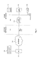
- Fig. 1 shows a home network 100 with a computer 101, game console 102 and digital television set-top box 103 connected to the Internet 120 via a residential gateway 104 and access network 110.
- the home devices 101, 102 and 103 are supposed to be ITU-T G.hn compliant.
- Fig. 1 further shows an analysis platform according to the present invention, i.e. an analysis application 130 running on a remote server to analyse parameter values of the home network's physical layer. The results of the analysis are associated with a database listing possible problems and which are associated with respective instruction information for an user in the home. Then the information is provided to the user, or to any other location where this information may be useful.
- Different types of problems can for instance be diagnosed: abnormal noise, abnormal channel frequency response, channel asymmetry, channel or transceivers non-linearity.
- Corrective actions can be for instance moving the home network device away from the noise source, or installing a noise filter between the noise source and the home network device.
- the noise level can be measured directly by the home network device.
- typically wireless devices as for instance WiFi devices report the noise level for each frequency channels in which they are authorized to emit.
- the noise level can be derived from the standardized parameters. These parameters can for instance comprise Signal-to-Noise Ratio (SNR), and Channel Frequency Response (CFR).
- SNR Signal-to-Noise Ratio
- CFR Channel Frequency Response
- Noise Level dBm / Hz TxPSD dBm / Hz + CFR dB - SNR dB ; where TxPSD is the transmitted signal PSD, which is a known parameter, and which is different for each home networking technology standard.
- Impulse noise can be monitored by means of for instance error counters (BER counter) or retransmission counters for the technologies for which an automatic retransmission mechanism is foreseen.
- BER counter error counters
- retransmission counters for the technologies for which an automatic retransmission mechanism is foreseen.
- the channel frequency response (or insertion loss) from a node A to a node B should be the same as the insertion loss from node B to node A (provided that both nodes have the same impedance).
- a typical example where this is not the case is a coaxial cable network, where an unidirectional CATV amplifier has been inserted between the two nodes. Because of that unidirectional amplifier, there can be a strong attenuation difference between the two directions, up to the point that the bitrates needed to offer the target service is not reachable anymore. Tracking the difference between the channel frequency responses measured between the two same nodes but in opposite directions can be done to diagnose such kind of problem.
- an asymmetry in communications performances can be found if a node acts as a communication relay between two other nodes, located in different areas, and if a disturber impacts specifically one of these areas. In that case, the throughput from node A to B will be different from the throughput from node B to A. When this asymmetry is detected, it can be used to diagnose the presence of a disturber specific to a given location.
- OFDM Orthogonal-Frequency-Division-Multiplexing
- POTS Plain Old Telephony System
- non-linearity may be the consequence of broken or poor quality transceivers, and therefore impact not only phone wires but any other medium.
- the analysis platform can be located at different locations in the network. Similarly, the associated method can be performed at different locations. The communication of respective information is possible towards different locations in the network. Although preferred, the location of the analysis platform does not have to correspond to the location of the user interface. Below, some preferred embodiments are described.
- An analysis platform can be implemented directly in the home networking nodes. Once established, communications to the user interface of the problem information and possibly solution information can be performed in different ways.
- the respective information is displayed on the home network node itself.
- power line adapters with an LCD screen are already available on the market today. Such a screen could be used to display analysis information.
- the main advantage of that solution is that the end customer, associated with the user interface, immediately sees the analysis result (problem information, optionally solution information). If this analysis reports a bad link quality, due to channel impairment or abnormal noise, the adapter can be moved to another position (e.g. in another wall plug in the case of a power line adapter) to see of the link quality is improved.
- a node's web management interface could be used. Even if the home network nodes act as a bridge at layer 2 (according to ISO model), a web server accessible via a dedicated IP address is usually embedded in each home networking node, at least for management purpose. Various analysis information (problem information and optionally solution information) could be provided via that web server as well.
- the home gateway is actually acting as a gateway between the access network and the home network.
- This home gateway can communicate with all the home network nodes, whatever the network technology (wired or wireless).
- a web server is always implemented in that gateway for management purpose. This server can be used to provide analysis information (problem information and optionally solution information)to the end-customers.
- Implementing the analysis engine in the home gateway provides the additional advantage that the analysis can be based on the correlation of parameters measured by all the home network nodes of the house, for all the home networking technologies used in that house, and not only limited to a given medium (given physical layer technology).
- the analysis engine can be implemented in a remote server, accessing the parameters measured by the home network nodes via the internet.
- a web server can be implemented in that remote application, where the service provider and the end-customers can log in to access the analysis information (problem information and optionally solution information).
Landscapes
- Engineering & Computer Science (AREA)
- Computer Networks & Wireless Communication (AREA)
- Signal Processing (AREA)
- Human Computer Interaction (AREA)
- Environmental & Geological Engineering (AREA)
- Automation & Control Theory (AREA)
- Monitoring And Testing Of Transmission In General (AREA)
- Maintenance And Management Of Digital Transmission (AREA)
- Small-Scale Networks (AREA)
- Telephonic Communication Services (AREA)
Abstract
Description
- The present invention relates to the field of methods and devices for improving the quality (stability and performance) of home network infrastructure.
- Residential internet connectivity traditionally consists of single voice-band modem, a Digital Subscriber Line or DSL modem, or a coax-cable modem, connected to a computer in the house. With the arrival of new applications and technologies, such as digital television, on-line gaming and home automation, the Internet access needs to be extended to various types of home devices, such as a set-top box, a game console, a home automation system, plural desktops or laptops, etc. All those home devices are then typically interconnected by means of a home network, which need to be set up and configured. A home network typically accesses the Internet via a home network gateway or residential gateway, which is connected to an access network via a traditional DSL modem or coax-cable modem.
- The interconnectivity between two devices is typically based on, typically already existing, in-house media such as twisted pair phone wires, electrical power wires and/or coax-cables. Also, wireless technologies like WiFi may be used in a home network.
- Most of the time, the in-house available media typically suffers from a low quality physical layer offering poor immunity for interference in-house. Twisted pair phone wires are usually slightly twisted. Electrical power wires typically consist of low category cable that is not twisted at all. As a result, these existing media are usually very sensitive to various kinds of noise. This is also the case at least to a certain extent for most of the existing in-house networking technologies.
- The communication links between two in-house devices may be impacted to such an extent that the usable bandwidth between the two nodes is drastically reduced, such that the intended service cannot be provided.
- If a communication problem occurs between two different home networking devices, it is in practice left to the end user to diagnose the problem and to solve it usually without any assistance. Only a few advices may be given via the operator helpdesk, but the responsibility of the operator is usually limited to the access network only, and any problem occurring in a home network area is responsibility of the end user.
- An objective of the present invention is to disclose a home network physical layer diagnosis platform and method that will overcome at least one of the above mentioned problems. More particularly, it is an objective to disclose such a platform and method that enables the user to improve the quality of in-house data links between two devices.
- This is achieved by the characterizing features of
claim 1. According to a first aspect of the present invention a home network physical layer analysis platform is disclosed comprising a collection engine adapted for receiving information indicative for stability and performance (or quality) of an existing home network physical layer configuration from one or more home network devices, each of the network devices being connected in the home network by means of respective network technology; an analysis engine, adapted for analyzing the information to identify whether substantial network connectivity problems exist in the home network, and for associating the information with a problem out of a set of predetermined problems, if this is the case; a communication means for communicating the problem (or problem information) to a user interface, such that the respective user is informed about the problem. - According to preferred embodiments of the present invention a home network physical layer analysis platform is disclosed, wherein the analysis engine is adapted for identifying whether substantial network connectivity problems exist in the home network by comparing the information with reference information accessible by the platform.
- The reference information can be, completely or at least in part, network technology dependent.
- According to preferred embodiments of the present invention a home network physical layer analysis platform is disclosed, wherein the analysis engine is adapted for associating the information with a problem out of a set of predetermined problems by comparing the information with a predetermined set of criteria, the criteria being associated with the set of predetermined problems.
- According to preferred embodiments of the present invention a home network physical layer analysis platform is disclosed, further comprising a solution instruction engine adapted for retrieving solution information for the problem, and wherein the communication means is adapted for communicating the solution information together with the problem to the user interface.
- According to preferred embodiments of the present invention a home network physical layer analysis platform is disclosed, wherein information indicative for stability and performance of an existing home network physical layer comprises noise information.
- According to preferred embodiments of the present invention a home network physical layer analysis platform is disclosed, wherein information indicative for stability and performance of an existing home network physical layer comprises at least one of channel frequency response information, channel asymmetry information or information relating to channel non-linearity or transceiver non-linearity.
- According to preferred embodiments of the present invention a home network physical layer analysis platform is disclosed, wherein the collection engine, the analysis engine, and the communication engine are controlled to iteratively receive information indicative for stability and performance of an existing home network physical layer configuration from one or more home network devices, to analyze the information, determine a possible problem, and communicate the problem, optionally with solution information, to a user interface.
- According to preferred embodiments of the present invention a home network physical layer analysis platform is disclosed, wherein the home network comprises a home network gateway and wherein the home network physical layer analysis platform is integrated in the home network gateway.
- According to preferred embodiments of the present invention the home network physical layer analysis platform is being integrated in a remote server which is connected to the home network over the internet.
- According to preferred embodiments of the present invention the home network physical layer analysis platform is being integrated in at least one home network device.
- According to preferred embodiments of the present invention the home network physical layer analysis platform is being adapted for use in a G.hn home network.
- According to preferred embodiments of the present invention a home network physical layer analysis platform is disclosed, wherein the user interface is located at a remote server which is connected to the home network over the internet.
- According to preferred embodiments of the present invention a home network physical layer analysis platform is disclosed, wherein the user interface is located at a home network gateway of the home network.
- According to preferred embodiments of the present invention a home network physical layer analysis platform is disclosed, wherein the user interface is integrated in at least one home network device.
- According to a second aspect of the present invention a method is disclosed for improving a home network physical layer, comprising; receiving information indicative for stability and performance of an existing home network physical layer configuration from one or more home network devices, each of the network devices being connected in the home network by means of respective network technology; analyzing the information to identify whether substantial network connectivity problems exist in the home network, and for associating the information with a problem out of a set of predetermined problems, if this is the case; communicating the problem to a user interface, such that the respective user is informed about the problem.
- According to preferred embodiments of the present invention, the method comprises identifying whether substantial network connectivity problems exist in the home network by comparing the information with reference information accessible by the platform.
- According to preferred embodiments of the present invention, the method comprises associating the information with a problem out of a set of predetermined problems by comparing the information with a predetermined set of criteria, the criteria being associated with the set of predetermined problems.
- According to preferred embodiments of the present invention the method further comprises retrieving solution information for the problem, and communicating the solution information together with the problem to the user interface. The solution information comprises information which allows the user associated with the user interface to solve an existing connectivity problem in the home network.
- According to preferred embodiments of the present invention a method is disclosed wherein information indicative for stability and performance of an existing home network physical layer comprises noise information.
- According to preferred embodiments of the present invention a method is disclosed, wherein information indicative for stability and performance of an existing home network physical layer comprises at least one of channel frequency response information, channel asymmetry information or information relating to channel non-linearity or transceiver non-linearity.
- According to preferred embodiments of the present invention a method is disclosed, wherein the collection engine, the analysis engine, and the communication engine are controlled to iteratively receive information indicative for stability and performance of an existing home network physical layer configuration from one or more home network devices, to analyze the information, determine a possible problem, and communicate the problem with the solution information to a user interface.
- According to preferred embodiments of the present invention a method is disclosed, wherein analyzing is performed in a home network gateway.
- According to preferred embodiments of the present invention a method is disclosed, wherein analyzing is performed in a remote server which is connected to a home network over the internet.
- According to preferred embodiments of the present invention a method is disclosed, wherein analyzing is performed in at least one home network device.
- According to preferred embodiments of the present invention a method is disclosed, used for a home network which is a G.hn home network.
- According to preferred embodiments of the present invention a method is disclosed, wherein the communication occurs to a user interface located at a remote server which is connected to the home network over the internet.
- According to preferred embodiments of the present invention a method is disclosed, wherein the communication occurs to a user interface located at a home network gateway of a home network.
- According to preferred embodiments of the present invention a method is disclosed, wherein the communication occurs to a user interface located at a one home network device.
- According to a third aspect of the present invention a computer program is disclosed comprising computer program code means adapted to perform all the steps of claims 12 to 25 when the program is run on a computer.
- Further aspects of the present invention are described by the dependent claims. The features from the dependent claims, features of any of the independent claims and any features of other dependent claims may be combined as considered appropriate to the person of ordinary skill, and not only in the particular combinations as defined by the claims.
- The accompanying drawings are used to illustrate embodiments of the present invention.
-
Fig. 1 illustrates a typical diagram showing the different network domains (internet/access network/home network), wherein a home network physical layer analysis platform is embodied as a software application on a remote server. -
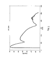
Fig. 2 illustrates the effect of a 100m bridge tap on the channel frequency response of a longer loop. -
Fig. 3 illustrates the impact of a capacitive device on the power line channel frequency response, in the graph. The drawing above the graph illustrates the topology of the capacitive device. The capacitive device is characterised by a capacitor of 100nF having a self-resonant frequency of 5Mhz and a quality factor of 10. -
Fig. 4 illustrates the results of a Monte-Carlo simulation of channel frequency response (dB) versus frequency (Hz) of various power lines networks. The upper, black curves are non-impaired cases, the lower, dark grey curves are the same cases as the upper curves but impaired by a capacitive devices (Monte-Carlo simulation ranges: between 3 and 20 branches in the home network topology, each branch between 5m and 30m, impairment located anywhere on the first branch, capacitor between 10 and 100nF, with self-resonant frequency between 1 and 10MHz and quality factor between 1 and 100.) - Reference signs are chosen such that they are the same for similar or equal elements or features in different figures or drawings.
- The description of aspects of the present invention is performed by means of particular embodiments and with reference to certain drawings but the invention is not limited thereto. Depicted figures are only schematic and should not be considered as limiting.
- In the description of certain embodiments according to the present invention, various features are sometimes grouped together in a single embodiment, figure, or description thereof for the purpose of aiding in the understanding of one or more of the various inventive aspects. This is not to be interpreted as if all features of the group are necessarily present to solve a particular problem. Inventive aspects may lie in less than all features of such a group of features present in the description of a particular embodiment.
- A main aspect of the present disclosure is to develop a generic diagnosis engine for the home network, providing to the end customer information about the problems impacting the performances of its home network and recommendations on how to solve those problems.
- This invention is particularly valuable with the upcoming technologies like G.hn. offering a common interface for home networks running on different media.
- The G.hn or ITU-T 9660 Recommendation is a standard specification for wired home networks that covers twisted pair phone lines, electrical power wires and coax cables as possible media for in-house data transmission.
-
Fig. 1 shows ahome network 100 with acomputer 101,game console 102 and digital television set-top box 103 connected to theInternet 120 via aresidential gateway 104 andaccess network 110. Thehome devices Fig. 1 further shows an analysis platform according to the present invention, i.e. ananalysis application 130 running on a remote server to analyse parameter values of the home network's physical layer. The results of the analysis are associated with a database listing possible problems and which are associated with respective instruction information for an user in the home. Then the information is provided to the user, or to any other location where this information may be useful. - Different types of problems can for instance be diagnosed: abnormal noise, abnormal channel frequency response, channel asymmetry, channel or transceivers non-linearity.
-
- With the exception of coaxial cable, which is very well protected against external noise source due to the cable shield, all the potential media used for the home networking (phone lines, power lines, wireless) show a very high susceptibility to pick up radiated noise from all kind of house hold appliances (well-known noise sources are i.e. neon and economic light, dc/dc converters, motors from vacuum cleaners and washing machines, ...). The in-house appliances can generate also a significant level of impulse noise that may degrade the transmission performance in terms of Bit Error Rate (BER) and throughput.
- It is very valuable to know for the end-customer whether an abnormal noise level is affecting his home network, as corrective actions are often possible. Corrective actions can be for instance moving the home network device away from the noise source, or installing a noise filter between the noise source and the home network device.
- Depending on the home networking technology, often the noise level can be measured directly by the home network device. For instance, typically wireless devices as for instance WiFi devices report the noise level for each frequency channels in which they are authorized to emit.
- For other technologies, like HPNA, Moca, HomePlug, that usually comply to a standard like TR-098, the noise level can be derived from the standardized parameters. These parameters can for instance comprise Signal-to-Noise Ratio (SNR), and Channel Frequency Response (CFR). The following relationship can be used :

where TxPSD is the transmitted signal PSD, which is a known parameter, and which is different for each home networking technology standard. - Impulse noise can be monitored by means of for instance error counters (BER counter) or retransmission counters for the technologies for which an automatic retransmission mechanism is foreseen.
- Different levels of analysis (can also be called diagnosis) are possible:
- Determining whether the noise level is normal or not, or in other words, detecting that the home network is impacting by an abnormal noise disturber or not. This can be done by comparing the measured noise level to an expected noise level, derived from standard, for instance EMC regulations or from experience.
- Identifying the disturber type (neon light, dc/dc converter, motor ...). This is very valuable for the end-customer as it will facilitate the identification of the disturber and therefore help the customer to take corrective actions. This can be achieved by comparing the measured noise level to a database of well-known disturbers "signatures" (typical noise emission spectrum specific to each particular disturber type).
- Many home networking technologies, at least all the ones compliant to technical report TR-098, report the channel frequency response as a standardized parameter. This corresponds to the channel attenuation (or insertion loss) as function of the frequency, in the bandwidth range that is allowed for that technology. The expected values are dependent on the specific medium, but in many cases, the expected values (or value ranges) are known due to conformity with a standard, mathematical simulation models or experience. A deviation with regard to those expected values can be detected and conclusions can be derived on the presence of channel impairment. Those impairments are also specific to each medium or home network technology. Some examples of known types of impairment that can be detected in the channel frequency response are the following, for different type of network technology:
- Phone wires :
- Phone wires models exist, especially in the case of DSL communication. It is known that the attenuation in function of frequency should follow a 1/sqrt (f) curve for a straight loop. A typical deviation to this law is very often a consequence of a "bridged-tap" (being an additional wire segment connected to the main loop). This can be detected in the channel frequency response detecting regularly-spaced dips in the curve, as illustrated on
Figure 2 .
- Phone wires models exist, especially in the case of DSL communication. It is known that the attenuation in function of frequency should follow a 1/sqrt (f) curve for a straight loop. A typical deviation to this law is very often a consequence of a "bridged-tap" (being an additional wire segment connected to the main loop). This can be detected in the channel frequency response detecting regularly-spaced dips in the curve, as illustrated on
- Coax cable:
- Coaxial cable technology usually exhibits very low losses, which makes the channel frequency response quite flat.
- Nevertheless, it is very often the case when the channel is not made of a single straight cable, but is made of several branches interconnected via passive power splitters. If all the branches are not properly terminated by matched impedance, reflections will occur and the same phenomena as the "bridge-tap" affecting phone lines will happen. This will result in a similar "signature" in the channel frequency response (regularly-spaced dips) that can be detected.
- Another type of impairment can be caused by too many passive power splitters being used in cascade. As those splitters are usually low-cost resistive splitters, each of them introduces an extra attenuation. If too many splitters are used in cascade, the attenuations will sum up and can become too high and not compatible anymore with the bitrates needed to offer the target service.
- Power lines:
- Power line networks are, by design, made of many branches.
- Therefore, "bridge-tap" effects as described above occur all the time and can be seen as inherent impairment of the network. Other factors are also known to impair the power line channel. Especially all kinds of capacitive devices that may be connected to the power line are known to act as a short circuit at high frequencies used by home networking communications. Those capacitive devices may be found for instance in the EMI filter of many house hold appliances (so-called X2 capacitor). Very common lightning protection devices made of Metal-Oxide Varistor (MOV) also exhibit a capacitive behavior that impairs the power line communication channel.
- This effect is illustrated on
Figure 3 . As one can see, the channel frequency shows a lot of variation because of the "bridge-tap" effect due to the branches present in the network topology. This effect is already responsible for a 10 to 20dB of average signal attenuation. When the capacitive device is inserted, the curve is even more shifted down, resulting is a much higher attenuation. - The results of a Monte Carlo simulation (resulting of many cases generated randomly within some boundaries) are shown on
Figure 4 . This shows that, independently of the home network topology, when the power line channel is impacted, the average attenuation is always higher than without the presence of a capacitive impairment (the lower dark grey curves are always below the upper black curves in average). This proves that it is statistically possible to determine the presence of the capacitive impairment from the channel frequency response level. This element can be used to diagnose an abnormal, impaired, power line channel. For example, the simulation results tend to prove that if the attenuation at 10MHz is higher than 50dB, the probability to have an impaired case is very high.
- Wireless :
- In-house wireless propagation environments are composed of a large number of multipaths. This is due to the reflections of the transmitted signals. As for the "bridged-tap" effect for wired communications, this multipath environment will cause the rise of the channel frequency-selectivity which is illustrated in
Fig. 3 . This is expected to be the major impairment for wireless communication systems.
- In-house wireless propagation environments are composed of a large number of multipaths. This is due to the reflections of the transmitted signals. As for the "bridged-tap" effect for wired communications, this multipath environment will cause the rise of the channel frequency-selectivity which is illustrated in
- As long as the propagation medium is made of passive and reciprocal material elements (like wires), the channel frequency response (or insertion loss) from a node A to a node B should be the same as the insertion loss from node B to node A (provided that both nodes have the same impedance).
- A typical example where this is not the case is a coaxial cable network, where an unidirectional CATV amplifier has been inserted between the two nodes. Because of that unidirectional amplifier, there can be a strong attenuation difference between the two directions, up to the point that the bitrates needed to offer the target service is not reachable anymore. Tracking the difference between the channel frequency responses measured between the two same nodes but in opposite directions can be done to diagnose such kind of problem.
- For wireless networks, an asymmetry in communications performances can be found if a node acts as a communication relay between two other nodes, located in different areas, and if a disturber impacts specifically one of these areas. In that case, the throughput from node A to B will be different from the throughput from node B to A. When this asymmetry is detected, it can be used to diagnose the presence of a disturber specific to a given location.
- Most home networking technologies are based on multi-carriers, Orthogonal-Frequency-Division-Multiplexing (OFDM) techniques. It is well-known that every transmission technique based on an OFDM is very sensitive to channel non-linearity. Indeed, non-linearity of the channel induces intermodulation distortion (a signal emitted on a given frequency 'leaks' to other frequencies, impacting neighboring carriers), which has a strong impact on the transmission performance.
- A well-known example of this phenomenon in the DSL domain is the interference with Plain Old Telephony System(POTS) equipment (phones, faxes, ...). This type of equipment usually exhibits non-linear impedance in the DSL frequency band.
- When connected to a twisted pair carrying DSL signal, this non-linear impedance induces intermodulation distortion of the DSL signal which results in a severe degradation of the performance. So-called 'DSL splitter' or 'in-line filters' have to be installed on those equipments to isolate them from the DSL signals.
- The same problem will impact home networking technologies such as HomePNA or G.hn running over phone wires.
- Note that non-linearity may be the consequence of broken or poor quality transceivers, and therefore impact not only phone wires but any other medium.
- The diagnosis of such kind of problems may be achieved by various ways, some of which are explained below:
- the interference due to non-linearity increases with the transmitted signal power. It can be detected by the fact that an increase of the transmitted signal power by x dB does not result in an increase of SNR by x dB (that should be the case for a purely linear system). Therefore, non-linearity can be detected by comparing 2 SNR measurements performed with 2 different transmitted signal powers.
- Other tests, specific to OFDM, may also be performed, like the MTPR (Multi-Tone Power Ratio) that is often used to characterize the end-to-end system linearity.
- The analysis platform can be located at different locations in the network. Similarly, the associated method can be performed at different locations. The communication of respective information is possible towards different locations in the network. Although preferred, the location of the analysis platform does not have to correspond to the location of the user interface. Below, some preferred embodiments are described.
- An analysis platform can be implemented directly in the home networking nodes. Once established, communications to the user interface of the problem information and possibly solution information can be performed in different ways.
- According to preferred embodiments, the respective information is displayed on the home network node itself. For instance, power line adapters with an LCD screen are already available on the market today. Such a screen could be used to display analysis information. The main advantage of that solution is that the end customer, associated with the user interface, immediately sees the analysis result (problem information, optionally solution information). If this analysis reports a bad link quality, due to channel impairment or abnormal noise, the adapter can be moved to another position (e.g. in another wall plug in the case of a power line adapter) to see of the link quality is improved.
- According to other embodiments, a node's web management interface could be used. Even if the home network nodes act as a bridge at layer 2 (according to ISO model), a web server accessible via a dedicated IP address is usually embedded in each home networking node, at least for management purpose. Various analysis information (problem information and optionally solution information) could be provided via that web server as well.
- Implementing the analysis engine directly in the home networking nodes allows analysis which is based on the correlation of parameters measured by all the nodes connected on the same physical medium, as a common physical medium is usually seen as a broadcast domain where all nodes connected to it can communicate with each other.
- As illustrated on
Figure 4 , the home gateway is actually acting as a gateway between the access network and the home network. This home gateway can communicate with all the home network nodes, whatever the network technology (wired or wireless). A web server is always implemented in that gateway for management purpose. This server can be used to provide analysis information (problem information and optionally solution information)to the end-customers. - Implementing the analysis engine in the home gateway provides the additional advantage that the analysis can be based on the correlation of parameters measured by all the home network nodes of the house, for all the home networking technologies used in that house, and not only limited to a given medium (given physical layer technology).
- Because all the parameters needed for analysis are usually accessible remotely (typically via SNMP or TR-069 protocols), the analysis engine can be implemented in a remote server, accessing the parameters measured by the home network nodes via the internet. A web server can be implemented in that remote application, where the service provider and the end-customers can log in to access the analysis information (problem information and optionally solution information).
- Implementing the analysis in a remote application allows some analysis based on the correlation of the parameters between all the customers monitored by the remote application (typically all the customers of the service provider).
- It should be noted that according to embodiments of the present invention, different locations where the analysis engine can be implemented are described. Also different options exist as to where the problem information, and optionally solution information, is communicated to the user. These locations do not necessarily have to correspond. The present invention can for instance be implemented in such a way that the analysis platform is implemented (and thus performed) in a remote application, whereby the analysis result (problem information, optionally solution information) is forwarded to the home gateway or directly to the home networking nodes to be displayed to the end customer by means of an associated user interface as for instance a display.
- While some embodiments described herein include some but not other features included in other embodiments, combinations of features of different embodiments are meant to be within the scope of the invention, and form different embodiments, as would be understood by the skilled person.
Claims (15)
- A home network physical layer analysis platform comprising:- a collection engine adapted for receiving information indicative for stability and performance of an existing home network physical layer configuration from one or more home network devices, each of said network devices being connected in the home network by means of respective network technology;- an analysis engine, adapted for analysing said information to identify whether substantial network connectivity problems exist in the home network, and for associating said information with a problem out of a set of predetermined problems, if this is the case;- a communication means for communicating said problem to a user interface, such that the respective user is informed about said problem.
- A home network physical layer analysis platform according to claim 1, wherein said analysis engine is adapted for identifying whether substantial network connectivity problems exist in the home network by comparing said information with reference information accessible by said platform.
- A home network physical layer analysis platform according to any of the previous claims, wherein said analysis engine is adapted for associating said information with a problem out of a set of predetermined problems by comparing said information with a predetermined set of criteria, said criteria being associated with said set of predetermined problems.
- A home network physical layer analysis platform according to any of the previous applications, further comprising a solution instruction engine adapted for retrieving solution information for said problem, and wherein said communication means is adapted for communicating said solution information together with said problem to said user interface.
- A home network physical layer analysis platform according to any of the previous claims, wherein information indicative for stability and performance of an existing home network physical layer comprises noise information.
- A home network physical layer analysis platform according to any of the previous claims, wherein information indicative for stability and performance of an existing home network physical layer comprises at least one of channel frequency response information, channel asymmetry information or information relating to channel non-linearity or transceiver non-linearity.
- A home network physical layer analysis platform according to any of the previous claims, wherein said collection engine, said analysis engine, and said communication engine are controlled to iteratively receive information indicative for stability and performance of an existing home network physical layer configuration from one or more home network devices, to analyse said information, determine a possible problem, and communicate said problem to a user interface.
- A home network physical layer analysis platform according to claim 1, wherein said home network comprises a home network gateway and wherein said home network physical layer analysis platform is integrated in said home network gateway.
- A home network physical layer analysis platform according to claim 1, said home network physical layer analysis platform being integrated in a remote server which is connected to the home network over the internet.
- A home network physical layer analysis platform according to claim 1, said home network physical layer analysis platform being integrated in at least one home network device.
- A home network physical layer analysis platform according to any of the previous claims, wherein said user interface is located at a remote server which is connected to the home network over the internet.
- A home network physical layer analysis platform according to any of the previous claims, wherein said user interface is located at a home network gateway of said home network.
- A home network physical layer analysis platform according to any of the previous claims, wherein said user interface is integrated in at least one home network device.
- A method for improving a home network physical layer, comprising;- receiving information indicative for stability and performance of an existing home network physical layer configuration from one or more home network devices, each of said network devices being connected in the home network by means of respective network technology;- analysing said information to identify whether substantial network connectivity problems exist in the home network, and for associating said information with a problem out of a set of predetermined problems, if this is the case;- communicating said problem to a user interface, such that the respective user is informed about said problem.
- A computer program comprising comprising computer program code means adapted to perform all the steps of claim 14 when the program is run on a computer.
Priority Applications (7)
| Application Number | Priority Date | Filing Date | Title |
|---|---|---|---|
| EP11305095.9A EP2482490B1 (en) | 2011-01-31 | 2011-01-31 | Device and method for improving home network infrastructure |
| KR1020137022731A KR101603522B1 (en) | 2011-01-31 | 2012-01-24 | Device and method for improving home network infrastructure |
| US13/977,998 US9450832B2 (en) | 2011-01-31 | 2012-01-24 | Device and method for improving home network infrastructure |
| JP2013550852A JP6148624B2 (en) | 2011-01-31 | 2012-01-24 | Devices and methods for improving home network infrastructure |
| PCT/EP2012/051002 WO2012104165A1 (en) | 2011-01-31 | 2012-01-24 | Device and method for improving home network infrastructure |
| CN201280007089.3A CN103339900B (en) | 2011-01-31 | 2012-01-24 | Apparatus and method for improving home network infrastructure |
| JP2015150331A JP2016001898A (en) | 2011-01-31 | 2015-07-30 | Device and method for improving home network infrastructure |
Applications Claiming Priority (1)
| Application Number | Priority Date | Filing Date | Title |
|---|---|---|---|
| EP11305095.9A EP2482490B1 (en) | 2011-01-31 | 2011-01-31 | Device and method for improving home network infrastructure |
Publications (2)
| Publication Number | Publication Date |
|---|---|
| EP2482490A1 true EP2482490A1 (en) | 2012-08-01 |
| EP2482490B1 EP2482490B1 (en) | 2016-07-20 |
Family
ID=43827451
Family Applications (1)
| Application Number | Title | Priority Date | Filing Date |
|---|---|---|---|
| EP11305095.9A Active EP2482490B1 (en) | 2011-01-31 | 2011-01-31 | Device and method for improving home network infrastructure |
Country Status (6)
| Country | Link |
|---|---|
| US (1) | US9450832B2 (en) |
| EP (1) | EP2482490B1 (en) |
| JP (2) | JP6148624B2 (en) |
| KR (1) | KR101603522B1 (en) |
| CN (1) | CN103339900B (en) |
| WO (1) | WO2012104165A1 (en) |
Cited By (6)
| Publication number | Priority date | Publication date | Assignee | Title |
|---|---|---|---|---|
| EP2728801A1 (en) * | 2012-11-06 | 2014-05-07 | Alcatel-Lucent | Device and method for home network analysis |
| WO2015150745A1 (en) * | 2014-03-31 | 2015-10-08 | British Telecommunications Public Limited Company | Home network monitor |
| US10063433B2 (en) | 2014-08-11 | 2018-08-28 | Honeywell International Inc. | Remotely monitoring network diagnostics |
| US10531363B2 (en) | 2014-03-28 | 2020-01-07 | British Telecommunications Public Limited Company | Wireless internet access |
| US11337077B2 (en) | 2018-03-29 | 2022-05-17 | British Telecommunications Public Limited Company | Method of channel selection in a wireless network |
| US12137383B2 (en) | 2018-10-16 | 2024-11-05 | British Telecommunications Public Limited Company | Measuring channel performance in wireless local area networks |
Families Citing this family (7)
| Publication number | Priority date | Publication date | Assignee | Title |
|---|---|---|---|---|
| US9385780B2 (en) * | 2012-10-15 | 2016-07-05 | Ikanos Communications, Inc. | Method and apparatus for detecting and analyzing noise and other events affecting a communication system |
| CN103139028A (en) * | 2013-01-15 | 2013-06-05 | 中国电力科学研究院 | Intelligent home energy management system based on G.hn |
| CN104144090B (en) * | 2013-05-10 | 2018-04-27 | 中国电信股份有限公司 | The wired covering system of high speed building |
| CN103812702A (en) * | 2014-02-19 | 2014-05-21 | 深圳市海亿康科技有限公司 | Method for dynamically indicating network state of broadband power line |
| US9680843B2 (en) | 2014-07-22 | 2017-06-13 | At&T Intellectual Property I, L.P. | Cloud-based communication account security |
| US10425285B2 (en) * | 2015-05-21 | 2019-09-24 | Centurylink Intellectual Property Llc | Automatic noise profile generation |
| EP3739764B1 (en) * | 2019-05-17 | 2024-07-31 | Nokia Solutions and Networks Oy | Method and apparatus for determining a bridged tap length |
Citations (2)
| Publication number | Priority date | Publication date | Assignee | Title |
|---|---|---|---|---|
| EP1936875A1 (en) * | 2006-12-19 | 2008-06-25 | Broadcom Corporation | System and method for diagnosing a cabling infrastructure using a PHY |
| US20090316707A1 (en) * | 2008-06-18 | 2009-12-24 | Telect, Inc. | Services Switch Form Factor |
Family Cites Families (22)
| Publication number | Priority date | Publication date | Assignee | Title |
|---|---|---|---|---|
| JP2531826B2 (en) * | 1990-04-06 | 1996-09-04 | 日本電信電話株式会社 | Fault isolation method for communication system and fault detector used therefor |
| JPH03289735A (en) | 1990-04-06 | 1991-12-19 | Nippon Telegr & Teleph Corp <Ntt> | Home bus testing device |
| JP3289740B2 (en) | 1993-01-26 | 2002-06-10 | 船井電機株式会社 | Disc tray structure for disc players |
| JP3318289B2 (en) | 1999-08-10 | 2002-08-26 | 松下電送システム株式会社 | Home network gateway equipment |
| JP2002243591A (en) | 2001-02-22 | 2002-08-28 | Mitsubishi Electric Corp | Vehicle failure diagnosis device |
| US7603468B2 (en) | 2002-01-14 | 2009-10-13 | Agere Systems, Inc. | Home adaptive transceiver for home networking communication system |
| JP3794343B2 (en) | 2002-04-15 | 2006-07-05 | 松下電工株式会社 | Center server for monitoring and control system for housing complex |
| US20040049714A1 (en) * | 2002-09-05 | 2004-03-11 | Marples David J. | Detecting errant conditions affecting home networks |
| JP2004336235A (en) | 2003-05-02 | 2004-11-25 | Sony Corp | Remote diagnostic device and remote diagnostic system |
| JP2005032192A (en) | 2003-07-11 | 2005-02-03 | Sony Corp | Home network device support system, information registration and distribution device, and information distribution method |
| US20050114496A1 (en) * | 2003-10-31 | 2005-05-26 | Zheng Fang | Method and apparatus for monitoring network connectivity between a home network device and a network |
| US7809116B2 (en) | 2003-12-07 | 2010-10-05 | Adaptive Spectrum And Signal Alignment, Inc. | DSL system estimation including known DSL line scanning and bad splice detection capability |
| WO2008016585A2 (en) * | 2006-07-31 | 2008-02-07 | Adaptive Spectrum And Signal Alignment, Inc. | Method and apparatus for analyzing and mitigating noise in a digital subscriber line |
| US7885222B2 (en) * | 2006-09-29 | 2011-02-08 | Advanced Micro Devices, Inc. | Task scheduler responsive to connectivity prerequisites |
| TWI339964B (en) * | 2007-07-31 | 2011-04-01 | Ind Tech Res Inst | Management architecture and diagnostic method for remote configuration of heterogeneous local networks |
| US8473325B2 (en) * | 2007-10-12 | 2013-06-25 | Pie Digital, Inc. | System and method for automatic configuration and management of home network devices using a hierarchical index model |
| JP4859067B2 (en) | 2008-02-12 | 2012-01-18 | Kddi株式会社 | Remote failure response method and system for failure occurring in terminal |
| JP5230311B2 (en) | 2008-09-09 | 2013-07-10 | 沖電気工業株式会社 | Failure analysis system and failure analysis method |
| EP2394394B1 (en) * | 2009-02-06 | 2016-12-07 | Broadcom Corporation | Network measurements and diagnostics |
| US8214494B1 (en) * | 2009-05-18 | 2012-07-03 | Alarm.Com Incorporated | Network device management technology |
| US8515014B2 (en) * | 2009-11-30 | 2013-08-20 | At&T Intellectual Property I, L.P. | Methods, apparatus and articles of manufacture to characterize customer-premises networks |
| US20110137772A1 (en) * | 2009-12-07 | 2011-06-09 | At&T Mobility Ii Llc | Devices, Systems and Methods for SLA-Based Billing |
-
2011
- 2011-01-31 EP EP11305095.9A patent/EP2482490B1/en active Active
-
2012
- 2012-01-24 CN CN201280007089.3A patent/CN103339900B/en not_active Expired - Fee Related
- 2012-01-24 US US13/977,998 patent/US9450832B2/en active Active
- 2012-01-24 WO PCT/EP2012/051002 patent/WO2012104165A1/en not_active Ceased
- 2012-01-24 JP JP2013550852A patent/JP6148624B2/en not_active Expired - Fee Related
- 2012-01-24 KR KR1020137022731A patent/KR101603522B1/en not_active Expired - Fee Related
-
2015
- 2015-07-30 JP JP2015150331A patent/JP2016001898A/en active Pending
Patent Citations (2)
| Publication number | Priority date | Publication date | Assignee | Title |
|---|---|---|---|---|
| EP1936875A1 (en) * | 2006-12-19 | 2008-06-25 | Broadcom Corporation | System and method for diagnosing a cabling infrastructure using a PHY |
| US20090316707A1 (en) * | 2008-06-18 | 2009-12-24 | Telect, Inc. | Services Switch Form Factor |
Non-Patent Citations (2)
| Title |
|---|
| C-Y YANG C ET AL: "Method and System of Performance Monitoring to Detect VDSL Service Degradation", CYBER-ENABLED DISTRIBUTED COMPUTING AND KNOWLEDGE DISCOVERY (CYBERC), 2010 INTERNATIONAL CONFERENCE ON, IEEE, PISCATAWAY, NJ, USA, 10 October 2010 (2010-10-10), pages 468 - 475, XP031786429, ISBN: 978-1-4244-8434-8 * |
| NDO G ET AL: "An Adaptive Procedure for Impulsive Noise Mitigation over Power Line Channels", GLOBAL TELECOMMUNICATIONS CONFERENCE, 2009. GLOBECOM 2009. IEEE, IEEE, PISCATAWAY, NJ, USA, 30 November 2009 (2009-11-30), pages 1 - 6, XP031645709, ISBN: 978-1-4244-4148-8 * |
Cited By (8)
| Publication number | Priority date | Publication date | Assignee | Title |
|---|---|---|---|---|
| EP2728801A1 (en) * | 2012-11-06 | 2014-05-07 | Alcatel-Lucent | Device and method for home network analysis |
| US10531363B2 (en) | 2014-03-28 | 2020-01-07 | British Telecommunications Public Limited Company | Wireless internet access |
| WO2015150745A1 (en) * | 2014-03-31 | 2015-10-08 | British Telecommunications Public Limited Company | Home network monitor |
| US10015686B2 (en) | 2014-03-31 | 2018-07-03 | British Telecommunications Public Limited Company | Access point grouping based on performance and location |
| US11265740B2 (en) | 2014-03-31 | 2022-03-01 | British Telecommunications Public Limited Company | Home network monitor |
| US10063433B2 (en) | 2014-08-11 | 2018-08-28 | Honeywell International Inc. | Remotely monitoring network diagnostics |
| US11337077B2 (en) | 2018-03-29 | 2022-05-17 | British Telecommunications Public Limited Company | Method of channel selection in a wireless network |
| US12137383B2 (en) | 2018-10-16 | 2024-11-05 | British Telecommunications Public Limited Company | Measuring channel performance in wireless local area networks |
Also Published As
| Publication number | Publication date |
|---|---|
| US20130290507A1 (en) | 2013-10-31 |
| JP2014506750A (en) | 2014-03-17 |
| CN103339900B (en) | 2017-06-16 |
| EP2482490B1 (en) | 2016-07-20 |
| KR101603522B1 (en) | 2016-03-15 |
| CN103339900A (en) | 2013-10-02 |
| KR20130129432A (en) | 2013-11-28 |
| JP6148624B2 (en) | 2017-06-14 |
| JP2016001898A (en) | 2016-01-07 |
| US9450832B2 (en) | 2016-09-20 |
| WO2012104165A1 (en) | 2012-08-09 |
Similar Documents
| Publication | Publication Date | Title |
|---|---|---|
| EP2482490B1 (en) | Device and method for improving home network infrastructure | |
| US9042245B2 (en) | Network measurements and diagnostics | |
| US8687506B2 (en) | Identifying network performance alert conditions | |
| EP1728357B1 (en) | A system and method for the quality status analysis of an access network supporting broadband telecommunication services | |
| EP2680494A1 (en) | Home network trouble shooting | |
| EP2712160B1 (en) | Method and device for testing subscriber premises equipment | |
| US9526019B2 (en) | Method and system for diagnostics and troubleshooting in home network deployments | |
| EP2712096B1 (en) | Method and system for detecting a disturber in a PLC network | |
| US9641247B2 (en) | System and method for monitoring unknown resources | |
| EP2819269B1 (en) | Method and system for localizing a disturber in a PLC network | |
| EP3014861B1 (en) | Method for detecting a noise induced by a powerline system on a twisted pair cable | |
| EP2854299B1 (en) | Method and device for analyzing a communication line | |
| EP2733891A1 (en) | A device and method for quantifying network infrastructure degradation | |
| EP2728801B1 (en) | Device and method for home network analysis |
Legal Events
| Date | Code | Title | Description |
|---|---|---|---|
| PUAI | Public reference made under article 153(3) epc to a published international application that has entered the european phase |
Free format text: ORIGINAL CODE: 0009012 |
|
| AK | Designated contracting states |
Kind code of ref document: A1 Designated state(s): AL AT BE BG CH CY CZ DE DK EE ES FI FR GB GR HR HU IE IS IT LI LT LU LV MC MK MT NL NO PL PT RO RS SE SI SK SM TR |
|
| AX | Request for extension of the european patent |
Extension state: BA ME |
|
| 17P | Request for examination filed |
Effective date: 20130201 |
|
| 17Q | First examination report despatched |
Effective date: 20130419 |
|
| 111Z | Information provided on other rights and legal means of execution |
Free format text: AL AT BE BG CH CY CZ DE DK EE ES FI FR GB GR HR HU IE IS IT LI LT LU LV MC MK MT NL NO PL PT RO RS SE SI SK SM TR Effective date: 20130410 |
|
| RAP1 | Party data changed (applicant data changed or rights of an application transferred) |
Owner name: ALCATEL LUCENT |
|
| D11X | Information provided on other rights and legal means of execution (deleted) | ||
| GRAP | Despatch of communication of intention to grant a patent |
Free format text: ORIGINAL CODE: EPIDOSNIGR1 |
|
| INTG | Intention to grant announced |
Effective date: 20160308 |
|
| GRAS | Grant fee paid |
Free format text: ORIGINAL CODE: EPIDOSNIGR3 |
|
| GRAA | (expected) grant |
Free format text: ORIGINAL CODE: 0009210 |
|
| AK | Designated contracting states |
Kind code of ref document: B1 Designated state(s): AL AT BE BG CH CY CZ DE DK EE ES FI FR GB GR HR HU IE IS IT LI LT LU LV MC MK MT NL NO PL PT RO RS SE SI SK SM TR |
|
| REG | Reference to a national code |
Ref country code: GB Ref legal event code: FG4D |
|
| RIN1 | Information on inventor provided before grant (corrected) |
Inventor name: DROOGHAAG, BENOIT Inventor name: GACANIN, HARIS |
|
| REG | Reference to a national code |
Ref country code: CH Ref legal event code: EP |
|
| REG | Reference to a national code |
Ref country code: IE Ref legal event code: FG4D |
|
| REG | Reference to a national code |
Ref country code: AT Ref legal event code: REF Ref document number: 814850 Country of ref document: AT Kind code of ref document: T Effective date: 20160815 |
|
| REG | Reference to a national code |
Ref country code: DE Ref legal event code: R096 Ref document number: 602011028297 Country of ref document: DE |
|
| REG | Reference to a national code |
Ref country code: LT Ref legal event code: MG4D |
|
| REG | Reference to a national code |
Ref country code: NL Ref legal event code: MP Effective date: 20160720 |
|
| REG | Reference to a national code |
Ref country code: AT Ref legal event code: MK05 Ref document number: 814850 Country of ref document: AT Kind code of ref document: T Effective date: 20160720 |
|
| REG | Reference to a national code |
Ref country code: FR Ref legal event code: PLFP Year of fee payment: 7 |
|
| PG25 | Lapsed in a contracting state [announced via postgrant information from national office to epo] |
Ref country code: LT Free format text: LAPSE BECAUSE OF FAILURE TO SUBMIT A TRANSLATION OF THE DESCRIPTION OR TO PAY THE FEE WITHIN THE PRESCRIBED TIME-LIMIT Effective date: 20160720 Ref country code: RS Free format text: LAPSE BECAUSE OF FAILURE TO SUBMIT A TRANSLATION OF THE DESCRIPTION OR TO PAY THE FEE WITHIN THE PRESCRIBED TIME-LIMIT Effective date: 20160720 Ref country code: FI Free format text: LAPSE BECAUSE OF FAILURE TO SUBMIT A TRANSLATION OF THE DESCRIPTION OR TO PAY THE FEE WITHIN THE PRESCRIBED TIME-LIMIT Effective date: 20160720 Ref country code: IS Free format text: LAPSE BECAUSE OF FAILURE TO SUBMIT A TRANSLATION OF THE DESCRIPTION OR TO PAY THE FEE WITHIN THE PRESCRIBED TIME-LIMIT Effective date: 20161120 Ref country code: HR Free format text: LAPSE BECAUSE OF FAILURE TO SUBMIT A TRANSLATION OF THE DESCRIPTION OR TO PAY THE FEE WITHIN THE PRESCRIBED TIME-LIMIT Effective date: 20160720 Ref country code: IT Free format text: LAPSE BECAUSE OF FAILURE TO SUBMIT A TRANSLATION OF THE DESCRIPTION OR TO PAY THE FEE WITHIN THE PRESCRIBED TIME-LIMIT Effective date: 20160720 Ref country code: NO Free format text: LAPSE BECAUSE OF FAILURE TO SUBMIT A TRANSLATION OF THE DESCRIPTION OR TO PAY THE FEE WITHIN THE PRESCRIBED TIME-LIMIT Effective date: 20161020 Ref country code: NL Free format text: LAPSE BECAUSE OF FAILURE TO SUBMIT A TRANSLATION OF THE DESCRIPTION OR TO PAY THE FEE WITHIN THE PRESCRIBED TIME-LIMIT Effective date: 20160720 |
|
| PG25 | Lapsed in a contracting state [announced via postgrant information from national office to epo] |
Ref country code: SE Free format text: LAPSE BECAUSE OF FAILURE TO SUBMIT A TRANSLATION OF THE DESCRIPTION OR TO PAY THE FEE WITHIN THE PRESCRIBED TIME-LIMIT Effective date: 20160720 Ref country code: ES Free format text: LAPSE BECAUSE OF FAILURE TO SUBMIT A TRANSLATION OF THE DESCRIPTION OR TO PAY THE FEE WITHIN THE PRESCRIBED TIME-LIMIT Effective date: 20160720 Ref country code: PL Free format text: LAPSE BECAUSE OF FAILURE TO SUBMIT A TRANSLATION OF THE DESCRIPTION OR TO PAY THE FEE WITHIN THE PRESCRIBED TIME-LIMIT Effective date: 20160720 Ref country code: GR Free format text: LAPSE BECAUSE OF FAILURE TO SUBMIT A TRANSLATION OF THE DESCRIPTION OR TO PAY THE FEE WITHIN THE PRESCRIBED TIME-LIMIT Effective date: 20161021 Ref country code: LV Free format text: LAPSE BECAUSE OF FAILURE TO SUBMIT A TRANSLATION OF THE DESCRIPTION OR TO PAY THE FEE WITHIN THE PRESCRIBED TIME-LIMIT Effective date: 20160720 Ref country code: PT Free format text: LAPSE BECAUSE OF FAILURE TO SUBMIT A TRANSLATION OF THE DESCRIPTION OR TO PAY THE FEE WITHIN THE PRESCRIBED TIME-LIMIT Effective date: 20161121 Ref country code: BE Free format text: LAPSE BECAUSE OF FAILURE TO SUBMIT A TRANSLATION OF THE DESCRIPTION OR TO PAY THE FEE WITHIN THE PRESCRIBED TIME-LIMIT Effective date: 20160720 Ref country code: AT Free format text: LAPSE BECAUSE OF FAILURE TO SUBMIT A TRANSLATION OF THE DESCRIPTION OR TO PAY THE FEE WITHIN THE PRESCRIBED TIME-LIMIT Effective date: 20160720 |
|
| REG | Reference to a national code |
Ref country code: DE Ref legal event code: R097 Ref document number: 602011028297 Country of ref document: DE |
|
| PG25 | Lapsed in a contracting state [announced via postgrant information from national office to epo] |
Ref country code: RO Free format text: LAPSE BECAUSE OF FAILURE TO SUBMIT A TRANSLATION OF THE DESCRIPTION OR TO PAY THE FEE WITHIN THE PRESCRIBED TIME-LIMIT Effective date: 20160720 Ref country code: EE Free format text: LAPSE BECAUSE OF FAILURE TO SUBMIT A TRANSLATION OF THE DESCRIPTION OR TO PAY THE FEE WITHIN THE PRESCRIBED TIME-LIMIT Effective date: 20160720 |
|
| PLBE | No opposition filed within time limit |
Free format text: ORIGINAL CODE: 0009261 |
|
| STAA | Information on the status of an ep patent application or granted ep patent |
Free format text: STATUS: NO OPPOSITION FILED WITHIN TIME LIMIT |
|
| PG25 | Lapsed in a contracting state [announced via postgrant information from national office to epo] |
Ref country code: BG Free format text: LAPSE BECAUSE OF FAILURE TO SUBMIT A TRANSLATION OF THE DESCRIPTION OR TO PAY THE FEE WITHIN THE PRESCRIBED TIME-LIMIT Effective date: 20161020 Ref country code: SM Free format text: LAPSE BECAUSE OF FAILURE TO SUBMIT A TRANSLATION OF THE DESCRIPTION OR TO PAY THE FEE WITHIN THE PRESCRIBED TIME-LIMIT Effective date: 20160720 Ref country code: SK Free format text: LAPSE BECAUSE OF FAILURE TO SUBMIT A TRANSLATION OF THE DESCRIPTION OR TO PAY THE FEE WITHIN THE PRESCRIBED TIME-LIMIT Effective date: 20160720 Ref country code: DK Free format text: LAPSE BECAUSE OF FAILURE TO SUBMIT A TRANSLATION OF THE DESCRIPTION OR TO PAY THE FEE WITHIN THE PRESCRIBED TIME-LIMIT Effective date: 20160720 Ref country code: CZ Free format text: LAPSE BECAUSE OF FAILURE TO SUBMIT A TRANSLATION OF THE DESCRIPTION OR TO PAY THE FEE WITHIN THE PRESCRIBED TIME-LIMIT Effective date: 20160720 |
|
| 26N | No opposition filed |
Effective date: 20170421 |
|
| PG25 | Lapsed in a contracting state [announced via postgrant information from national office to epo] |
Ref country code: SI Free format text: LAPSE BECAUSE OF FAILURE TO SUBMIT A TRANSLATION OF THE DESCRIPTION OR TO PAY THE FEE WITHIN THE PRESCRIBED TIME-LIMIT Effective date: 20160720 |
|
| REG | Reference to a national code |
Ref country code: CH Ref legal event code: PL |
|
| PG25 | Lapsed in a contracting state [announced via postgrant information from national office to epo] |
Ref country code: MC Free format text: LAPSE BECAUSE OF FAILURE TO SUBMIT A TRANSLATION OF THE DESCRIPTION OR TO PAY THE FEE WITHIN THE PRESCRIBED TIME-LIMIT Effective date: 20160720 |
|
| PG25 | Lapsed in a contracting state [announced via postgrant information from national office to epo] |
Ref country code: CH Free format text: LAPSE BECAUSE OF NON-PAYMENT OF DUE FEES Effective date: 20170131 Ref country code: LI Free format text: LAPSE BECAUSE OF NON-PAYMENT OF DUE FEES Effective date: 20170131 |
|
| REG | Reference to a national code |
Ref country code: IE Ref legal event code: MM4A |
|
| PG25 | Lapsed in a contracting state [announced via postgrant information from national office to epo] |
Ref country code: LU Free format text: LAPSE BECAUSE OF NON-PAYMENT OF DUE FEES Effective date: 20170131 |
|
| REG | Reference to a national code |
Ref country code: FR Ref legal event code: PLFP Year of fee payment: 8 |
|
| PG25 | Lapsed in a contracting state [announced via postgrant information from national office to epo] |
Ref country code: IE Free format text: LAPSE BECAUSE OF NON-PAYMENT OF DUE FEES Effective date: 20170131 |
|
| PG25 | Lapsed in a contracting state [announced via postgrant information from national office to epo] |
Ref country code: MT Free format text: LAPSE BECAUSE OF NON-PAYMENT OF DUE FEES Effective date: 20170131 |
|
| PG25 | Lapsed in a contracting state [announced via postgrant information from national office to epo] |
Ref country code: AL Free format text: LAPSE BECAUSE OF FAILURE TO SUBMIT A TRANSLATION OF THE DESCRIPTION OR TO PAY THE FEE WITHIN THE PRESCRIBED TIME-LIMIT Effective date: 20160720 |
|
| PG25 | Lapsed in a contracting state [announced via postgrant information from national office to epo] |
Ref country code: HU Free format text: LAPSE BECAUSE OF FAILURE TO SUBMIT A TRANSLATION OF THE DESCRIPTION OR TO PAY THE FEE WITHIN THE PRESCRIBED TIME-LIMIT; INVALID AB INITIO Effective date: 20110131 |
|
| PG25 | Lapsed in a contracting state [announced via postgrant information from national office to epo] |
Ref country code: CY Free format text: LAPSE BECAUSE OF NON-PAYMENT OF DUE FEES Effective date: 20160720 |
|
| PG25 | Lapsed in a contracting state [announced via postgrant information from national office to epo] |
Ref country code: MK Free format text: LAPSE BECAUSE OF FAILURE TO SUBMIT A TRANSLATION OF THE DESCRIPTION OR TO PAY THE FEE WITHIN THE PRESCRIBED TIME-LIMIT Effective date: 20160720 |
|
| PG25 | Lapsed in a contracting state [announced via postgrant information from national office to epo] |
Ref country code: TR Free format text: LAPSE BECAUSE OF FAILURE TO SUBMIT A TRANSLATION OF THE DESCRIPTION OR TO PAY THE FEE WITHIN THE PRESCRIBED TIME-LIMIT Effective date: 20160720 |
|
| REG | Reference to a national code |
Ref country code: DE Ref legal event code: R079 Ref document number: 602011028297 Country of ref document: DE Free format text: PREVIOUS MAIN CLASS: H04L0012240000 Ipc: H04L0041000000 |
|
| PGFP | Annual fee paid to national office [announced via postgrant information from national office to epo] |
Ref country code: FR Payment date: 20211217 Year of fee payment: 12 |
|
| PG25 | Lapsed in a contracting state [announced via postgrant information from national office to epo] |
Ref country code: FR Free format text: LAPSE BECAUSE OF NON-PAYMENT OF DUE FEES Effective date: 20230131 |
|
| PGFP | Annual fee paid to national office [announced via postgrant information from national office to epo] |
Ref country code: GB Payment date: 20251211 Year of fee payment: 16 |
|
| PGFP | Annual fee paid to national office [announced via postgrant information from national office to epo] |
Ref country code: DE Payment date: 20251210 Year of fee payment: 16 |