EP2482410A1 - Relay and method for protecting transformer, transformer protecting system having the same - Google Patents
Relay and method for protecting transformer, transformer protecting system having the same Download PDFInfo
- Publication number
- EP2482410A1 EP2482410A1 EP20120152400 EP12152400A EP2482410A1 EP 2482410 A1 EP2482410 A1 EP 2482410A1 EP 20120152400 EP20120152400 EP 20120152400 EP 12152400 A EP12152400 A EP 12152400A EP 2482410 A1 EP2482410 A1 EP 2482410A1
- Authority
- EP
- European Patent Office
- Prior art keywords
- transformer
- current
- relay
- ratio
- voltage
- Prior art date
- Legal status (The legal status is an assumption and is not a legal conclusion. Google has not performed a legal analysis and makes no representation as to the accuracy of the status listed.)
- Granted
Links
Images


Classifications
-
- H—ELECTRICITY
- H02—GENERATION; CONVERSION OR DISTRIBUTION OF ELECTRIC POWER
- H02H—EMERGENCY PROTECTIVE CIRCUIT ARRANGEMENTS
- H02H7/00—Emergency protective circuit arrangements specially adapted for specific types of electric machines or apparatus or for sectionalised protection of cable or line systems, and effecting automatic switching in the event of an undesired change from normal working conditions
- H02H7/04—Emergency protective circuit arrangements specially adapted for specific types of electric machines or apparatus or for sectionalised protection of cable or line systems, and effecting automatic switching in the event of an undesired change from normal working conditions for transformers
-
- H—ELECTRICITY
- H01—ELECTRIC ELEMENTS
- H01F—MAGNETS; INDUCTANCES; TRANSFORMERS; SELECTION OF MATERIALS FOR THEIR MAGNETIC PROPERTIES
- H01F27/00—Details of transformers or inductances, in general
- H01F27/40—Structural association with built-in electric component, e.g. fuse
- H01F27/402—Association of measuring or protective means
-
- H—ELECTRICITY
- H01—ELECTRIC ELEMENTS
- H01H—ELECTRIC SWITCHES; RELAYS; SELECTORS; EMERGENCY PROTECTIVE DEVICES
- H01H47/00—Circuit arrangements not adapted to a particular application of the relay and designed to obtain desired operating characteristics or to provide energising current
- H01H47/02—Circuit arrangements not adapted to a particular application of the relay and designed to obtain desired operating characteristics or to provide energising current for modifying the operation of the relay
-
- H—ELECTRICITY
- H02—GENERATION; CONVERSION OR DISTRIBUTION OF ELECTRIC POWER
- H02H—EMERGENCY PROTECTIVE CIRCUIT ARRANGEMENTS
- H02H3/00—Emergency protective circuit arrangements for automatic disconnection directly responsive to an undesired change from normal electric working condition with or without subsequent reconnection ; integrated protection
- H02H3/26—Emergency protective circuit arrangements for automatic disconnection directly responsive to an undesired change from normal electric working condition with or without subsequent reconnection ; integrated protection responsive to difference between voltages or between currents; responsive to phase angle between voltages or between currents
- H02H3/28—Emergency protective circuit arrangements for automatic disconnection directly responsive to an undesired change from normal electric working condition with or without subsequent reconnection ; integrated protection responsive to difference between voltages or between currents; responsive to phase angle between voltages or between currents involving comparison of the voltage or current values at two spaced portions of a single system, e.g. at opposite ends of one line, at input and output of apparatus
-
- H—ELECTRICITY
- H02—GENERATION; CONVERSION OR DISTRIBUTION OF ELECTRIC POWER
- H02H—EMERGENCY PROTECTIVE CIRCUIT ARRANGEMENTS
- H02H7/00—Emergency protective circuit arrangements specially adapted for specific types of electric machines or apparatus or for sectionalised protection of cable or line systems, and effecting automatic switching in the event of an undesired change from normal working conditions
- H02H7/04—Emergency protective circuit arrangements specially adapted for specific types of electric machines or apparatus or for sectionalised protection of cable or line systems, and effecting automatic switching in the event of an undesired change from normal working conditions for transformers
- H02H7/055—Emergency protective circuit arrangements specially adapted for specific types of electric machines or apparatus or for sectionalised protection of cable or line systems, and effecting automatic switching in the event of an undesired change from normal working conditions for transformers for tapped transformers or tap-changing means thereof
-
- H—ELECTRICITY
- H02—GENERATION; CONVERSION OR DISTRIBUTION OF ELECTRIC POWER
- H02H—EMERGENCY PROTECTIVE CIRCUIT ARRANGEMENTS
- H02H3/00—Emergency protective circuit arrangements for automatic disconnection directly responsive to an undesired change from normal electric working condition with or without subsequent reconnection ; integrated protection
- H02H3/006—Calibration or setting of parameters
Definitions
- the present invention relates to a relay and method for protecting a transformer, and more particularly, to a relay and method for protecting a transformer capable of preventing a malfunction occurring when a transformation ratio of a transformer has been incorrectly set, and a transformer protecting system having the same.
- the conventional transformer protecting relay is configured to allow a user to set a transformation ratio of a transformer. That is, a user sets a voltage ratio of the transformer, and a current ratio between a primary current transformer and a secondary current transformer.
- the transformer protecting relay determines whether an accident has occurred or not.
- the conventional transformer protecting relay may have the following problem.
- the relay may malfunction.
- an aspect of the detailed description is to provide a relay and method for protecting a transformer capable of preventing a malfunction of a transformer by determining whether a transformation ratio of the transformer has been correctly set or not based on an inner algorithm, and a transformer protecting system having the same.
- Another aspect of the detailed description is to provide a relay and method for protecting a transformer capable of re-setting a transformation ratio by determining whether a transformation ratio of a transformer has been correctly set or not based on an inner algorithm and by informing a result of the determination to a user, and a transformer protecting system having the same.
- a transformer protecting relay comprising: an input module configured to input a voltage ratio of a transformer and a current ratio between a primary current transformer and a secondary current transformer connected to the transformer; and a control module configured to determine whether the transformer has been correctly set or not based on the voltage ratio and the current ratio.
- the transformer protecting relay may further comprise an output module configured to output a result of the determination to the outside.
- the control module may be configured to determine that the transformer has been incorrectly set if a value obtained by multiplying the voltage ratio by the current ratio is out of a predetermined range.
- a transformer protecting method using a transformer protecting relay comprising: receiving a voltage ratio of a transformer, and a current ratio between a primary current transformer and a secondary current transformer connected to the transformer; and determining whether the transformer has been correctly set or not based on the voltage ratio and the current ratio.
- the method may further comprise outputting a result of the determination to the outside.
- the step of determining whether the transformer has been correctly set or not may include comparing a value obtained by multiplying the voltage ratio by the current ratio with a predetermined range; determining that the transformer has been correctly set if the value is within the predetermined range as a result of the comparison; and determining that the transformer has been incorrectly set if the value is out of the predetermined range as a result of the comparison.
- a transformer protecting system comprising: a transformer having a predetermined voltage ratio, and configured to convert a voltage of an input side power unit and to supply the converted voltage to an output side power unit; a primary current transformer and a secondary current transformer connected to an input side and an output side of the transformer, respectively; a user's setting receiving unit configured to receive the voltage ratio of the transformer and the current ratio between the primary current transformer and the secondary current transformer; and a relay configured to determine whether the transformer has been correctly set or not by a user based on the voltage ratio and the current ratio.
- the transformer protecting system may further comprise an input side switch provided at the transformer and the primary current transformer, and configured to disconnect the transformer and the primary current transformer from each other according to a disconnection signal; and an output side switch provided at the transformer and the secondary current transformer, and configured to disconnect the transformer and the secondary current transformer from each other according to a disconnection signal.
- the relay may be configured to inform a result of the determination to the outside, and to generate the disconnection signal.
- a system accident due to a user's mistake may be prevented. This may enhance a system stability.
- whether a transformation ratio of the transformer has been correctly set or not by a user, etc. may be determined in advance, based on an inner algorithm. This may prevent a malfunction of the relay when the system is operated.
- a transformer protecting system comprises a transformer 10 having a predetermined voltage ratio, and configured to convert a voltage of an input side power unit and to supply the converted voltage to an output side power unit; a primary current transformer 20 and a secondary current transformer 30 connected to an input side and an output side of the transformer, respectively; a user's setting receiving unit (not shown) configured to receive the voltage ratio of the transformer and the current ratio between the primary current transformer and the secondary current transformer; and a relay 60 configured to determine whether the transformer has been correctly set or not by a user, based on the voltage ratio and the current ratio.
- the transformer protecting system may further comprise an input side switch 40 provided at the transformer 10 and the primary current transformer 20, and configured to disconnect the transformer 10 and the primary current transformer 20 from each other according to a disconnection signal.
- the transformer protecting system may further comprise an output side switch 50 provided at the transformer 10 and the secondary current transformer 30, and configured to disconnect the transformer 10 and the secondary current transformer 30 from each other according to a disconnection signal.
- the relay 60 may be configured to inform a result of the determination to the outside, and to generate the disconnection signal.
- the relay 60 In the occurrence of an error of the transformer 10, the relay 60 generates a disconnection signal to the input side switch 40 and the output side switch 50. For instance, if a ground fault has occurred on the transformer, current values of two ends of the transformer become greatly different from each other. This may cause a differential current between an input current and an output current of the relay 60, or a phase difference between an input current and an output current of the relay 60. Once the differential current or phase difference occurs, the relay 60 determines that an error has occurred, and transmits a disconnection signal to the input side switch 40 and the output side switch 50.
- the transformer protecting relay 60 comprises an input module 61 configured to input a voltage ratio of a transformer and a current ratio between a primary current transformer and a secondary current transformer connected to the transformer, and a control module 63 configured to determine whether the transformer has been correctly set or not based on the voltage ratio and the current ratio.
- the transformer protecting relay 60 may further comprise an output module 65 configured to output a result of the determination to the outside.
- the input module 61 may be configured to allow a user to directly input the voltage ratio and the current ratio, or configured to read a transformation ratio set by a user by being connected to the transformer 10, the primary current transformer 20 and the secondary current transformer 30.
- the control module 63 is configured to store therein an inner algorithm, and to verify a transformation ratio set by a user, etc. based on the inner algorithm. More concretely, the control module 63 may be configured to determine that the transformer has been incorrectly set if a value obtained by multiplying the voltage ratio by the current ratio is out of a predetermined range based on the inner algorithm.
- An electricity amount (power) of the transformer 10 may be preferably expressed by the following formula 1 with respect to the primary and secondary sides.
- V 1 ⁇ I 1 V 2 ⁇ I 2
- V 1 is a primary voltage
- V 2 is a secondary voltage
- I 1 is a primary current
- I 2 is a secondary current.
- the primary current and the secondary current are inversely proportional to each other. More concretely, in case of a step-down transformer where a secondary voltage is lower than a primary voltage, a secondary current becomes high to cause a current ratio to become great. On the other hand, in case of a step-up transformer where a secondary voltage is higher than a primary voltage, a secondary current becomes low to cause a current ratio to become small.
- the control module 63 calculates a value of 'K' based on the following formula 2, and determines that the transformer has been incorrectly set if the value of 'K' is out of a predetermined range based on '1'.
- V 1 ⁇ I 1 V 2 ⁇ I 2 K
- K is a constant, V 1 is a primary voltage, V 2 is a secondary voltage, I 1 is a primary current, and I 2 is a secondary current.
- the formula 2 may be derived from the formula 1, and the value of 'K' may have a value of '1', theoretically. Whether the transformer has been correctly set or not may be determined based on the value of 'K' calculated by the voltage ratio and the current ratio set by a user.
- FIGS. 2 and 3 will be explained an operation of the transformer protecting relay according to the present disclosure.
- a primary current transformer has 22.9 [kV]
- a secondary current transformer has 3.3 [kV]
- a primary current transformer has 400 [A]
- a secondary current transformer has 3000 [A].
- a primary current transformer has 22.9 [kV]
- a secondary current transformer has 3.3 [kV]
- a primary current transformer has 3000 [A]
- a secondary current transformer has 400 [A].
- the control module 61 presets a predetermined range of the value of 'K', e.g., 0.8 - 1.2, and determines whether the calculated value of 'K' is within the predetermined range. If the value of 'K' is out of the predetermined range, the output module 65 informs, through an external device, that the transformer has been incorrectly set, and requires a user to re-set the predetermined range of the value of 'K'.
- the external device may be a video device such as an LED or an LCD, or a display device, or an audio device such as an alarm and a beep.
- the output module 65 outputs, to the external device, a message indicating that the transformer has been incorrectly set, in the form of a signal.
- a transformer protecting method using a transformer protecting relay comprises a step of receiving a voltage ratio of a transformer, and a current ratio between a primary current transformer and a secondary current transformer connected to the transformer (S10), and a step of determining whether the transformer has been correctly set or not based on the voltage ratio and the current ratio (S20).
- the method further comprises a step of outputting a result of the determination to the outside (S30).
- the step of determining whether the transformer has been correctly set or not includes comparing a value obtained by multiplying the voltage ratio by the current ratio with a predetermined range (S23), determining that the transformer has been correctly set if the value is within the predetermined range as a result of the comparison (S25), and determining that the transformer has been incorrectly set if the value is out of the predetermined range as a result of the comparison (S27).
- S23 a value obtained by multiplying the voltage ratio by the current ratio with a predetermined range
- S25 determining that the transformer has been correctly set if the value is within the predetermined range as a result of the comparison
- S27 determining that the transformer has been incorrectly set if the value is out of the predetermined range as a result of the comparison
- An electricity amount (power) of the transformer may be preferably expressed by the formula 1 with respect to the primary and secondary sides. As can be seen from the formula 1, if the primary voltage and the secondary voltage are proportional to each other, the primary current and the secondary current are inversely proportional to each other.
- the transformer protecting relay 60 calculates a value of 'K' based on the formula 2, and determines that the transformer has been incorrectly set if the calculated value of 'K' is out of a predetermined range based on '1'.
- the formula 2 may be derived from the formula 1, and the value of 'K' may have a value of '1', theoretically. Whether the transformer has been correctly set or not may be determined based on the value of 'K' calculated by the voltage ratio and the current ratio set by a user.
- the transformer protecting relay 60 presets a predetermined range of the value of 'K', e.g., 0.8(K1) ⁇ 1.2(K2), and determines whether the calculated value of 'K' is within the predetermined range. If the value of 'K' is out of the predetermined range, the transformer protecting relay 60 informs a user through a warning message outputted to an output screen. More concretely, as shown in FIG. 3 , it is assumed, by a user's setting, that a primary current transformer has 22.9 [kV], a secondary current transformer has 3.3 [kV], a primary current transformer has 3000 [A], and a secondary current transformer has 400 [A].
- the transformer protecting relay 60 may output a warning message to an LED or an LCD, or may generate a warning sound through an alarm or a beep.
- whether a transformation ratio of the transformer has been correctly set or not may be determined based on an inner algorithm. If it is determined that the transformation ratio has been incorrectly set, a user may be informed to reset the transformation ratio. This may prevent a malfunction of the relay when the system is operated, and may enhance a system stability.
Landscapes
- Engineering & Computer Science (AREA)
- Power Engineering (AREA)
- Protection Of Transformers (AREA)
- Emergency Protection Circuit Devices (AREA)
Abstract
Description
- The present invention relates to a relay and method for protecting a transformer, and more particularly, to a relay and method for protecting a transformer capable of preventing a malfunction occurring when a transformation ratio of a transformer has been incorrectly set, and a transformer protecting system having the same.
- The conventional transformer protecting relay is configured to allow a user to set a transformation ratio of a transformer. That is, a user sets a voltage ratio of the transformer, and a current ratio between a primary current transformer and a secondary current transformer.
- This is implemented so as to make different electricity amounts input to the primary current transformer and the secondary current transformer equal. Based on the electricity amount of the same level, the transformer protecting relay determines whether an accident has occurred or not.
- However, the conventional transformer protecting relay may have the following problem. When the voltage ratio and the current ratio (transformation ratio) have been incorrectly set due to a user's mistake, etc., the relay may malfunction.
- Therefore, an aspect of the detailed description is to provide a relay and method for protecting a transformer capable of preventing a malfunction of a transformer by determining whether a transformation ratio of the transformer has been correctly set or not based on an inner algorithm, and a transformer protecting system having the same.
- Another aspect of the detailed description is to provide a relay and method for protecting a transformer capable of re-setting a transformation ratio by determining whether a transformation ratio of a transformer has been correctly set or not based on an inner algorithm and by informing a result of the determination to a user, and a transformer protecting system having the same.
- To achieve these and other advantages and in accordance with the purpose of this specification, as embodied and broadly described herein, there is provided a transformer protecting relay, the relay comprising: an input module configured to input a voltage ratio of a transformer and a current ratio between a primary current transformer and a secondary current transformer connected to the transformer; and a control module configured to determine whether the transformer has been correctly set or not based on the voltage ratio and the current ratio.
- The transformer protecting relay may further comprise an output module configured to output a result of the determination to the outside.
- The control module may be configured to determine that the transformer has been incorrectly set if a value obtained by multiplying the voltage ratio by the current ratio is out of a predetermined range.
- To achieve these and other advantages and in accordance with the purpose of this specification, as embodied and broadly described herein, there is also provided a transformer protecting method using a transformer protecting relay, the method comprising: receiving a voltage ratio of a transformer, and a current ratio between a primary current transformer and a secondary current transformer connected to the transformer; and determining whether the transformer has been correctly set or not based on the voltage ratio and the current ratio.
- The method may further comprise outputting a result of the determination to the outside.
- The step of determining whether the transformer has been correctly set or not may include comparing a value obtained by multiplying the voltage ratio by the current ratio with a predetermined range; determining that the transformer has been correctly set if the value is within the predetermined range as a result of the comparison; and determining that the transformer has been incorrectly set if the value is out of the predetermined range as a result of the comparison.
- To achieve these and other advantages and in accordance with the purpose of this specification, as embodied and broadly described herein, there is still also provided a transformer protecting system, comprising: a transformer having a predetermined voltage ratio, and configured to convert a voltage of an input side power unit and to supply the converted voltage to an output side power unit; a primary current transformer and a secondary current transformer connected to an input side and an output side of the transformer, respectively; a user's setting receiving unit configured to receive the voltage ratio of the transformer and the current ratio between the primary current transformer and the secondary current transformer; and a relay configured to determine whether the transformer has been correctly set or not by a user based on the voltage ratio and the current ratio.
- The transformer protecting system may further comprise an input side switch provided at the transformer and the primary current transformer, and configured to disconnect the transformer and the primary current transformer from each other according to a disconnection signal; and an output side switch provided at the transformer and the secondary current transformer, and configured to disconnect the transformer and the secondary current transformer from each other according to a disconnection signal. The relay may be configured to inform a result of the determination to the outside, and to generate the disconnection signal.
- In the present disclosure, a system accident due to a user's mistake may be prevented. This may enhance a system stability.
- In the present disclosure, whether a transformation ratio of the transformer has been correctly set or not by a user, etc. may be determined in advance, based on an inner algorithm. This may prevent a malfunction of the relay when the system is operated.
- Further scope of applicability of the present application will become more apparent from the detailed description given hereinafter. However, it should be understood that the detailed description and specific examples, while indicating preferred embodiments of the invention, are given by way of illustration only, since various changes and modifications within the spirit and scope of the invention will become apparent to those skilled in the art from the detailed description.
- The accompanying drawings, which are included to provide a further understanding of the invention and are incorporated in and constitute a part of this specification, illustrate exemplary embodiments and together with the description serve to explain the principles of the invention.
- In the drawings:
-
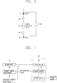
FIG. 1 is a view for explaining a transformer protecting system according to the present disclosure; -
FIGS. 2 and3 are views for explaining an operation of a transformer protecting relay according to the present disclosure; -
FIG. 4 is a block diagram schematically showing a configuration of a transformer protecting system according to the present disclosure; and -
FIGS. 5 and 6 are views schematically showing a transformer protecting method according to the present disclosure. - Description will now be given in detail of the exemplary embodiments, with reference to the accompanying drawings. For the sake of brief description with reference to the drawings, the same or equivalent components will be provided with the same reference numbers, and description thereof will not be repeated.
- Hereinafter, a relay and method for protecting a transformer, and a transformer protecting system having the same will be explained in more details with reference to the attached drawings.
- Referring to
FIG. 1 , a transformer protecting system according to the present disclosure comprises atransformer 10 having a predetermined voltage ratio, and configured to convert a voltage of an input side power unit and to supply the converted voltage to an output side power unit; aprimary current transformer 20 and asecondary current transformer 30 connected to an input side and an output side of the transformer, respectively; a user's setting receiving unit (not shown) configured to receive the voltage ratio of the transformer and the current ratio between the primary current transformer and the secondary current transformer; and arelay 60 configured to determine whether the transformer has been correctly set or not by a user, based on the voltage ratio and the current ratio. - The transformer protecting system may further comprise an
input side switch 40 provided at thetransformer 10 and the primarycurrent transformer 20, and configured to disconnect thetransformer 10 and the primarycurrent transformer 20 from each other according to a disconnection signal. - The transformer protecting system may further comprise an
output side switch 50 provided at thetransformer 10 and thesecondary current transformer 30, and configured to disconnect thetransformer 10 and thesecondary current transformer 30 from each other according to a disconnection signal. - The
relay 60 may be configured to inform a result of the determination to the outside, and to generate the disconnection signal. - In the occurrence of an error of the
transformer 10, therelay 60 generates a disconnection signal to theinput side switch 40 and theoutput side switch 50. For instance, if a ground fault has occurred on the transformer, current values of two ends of the transformer become greatly different from each other. This may cause a differential current between an input current and an output current of therelay 60, or a phase difference between an input current and an output current of therelay 60. Once the differential current or phase difference occurs, therelay 60 determines that an error has occurred, and transmits a disconnection signal to theinput side switch 40 and theoutput side switch 50. - Referring to
FIG. 4 , thetransformer protecting relay 60 comprises aninput module 61 configured to input a voltage ratio of a transformer and a current ratio between a primary current transformer and a secondary current transformer connected to the transformer, and acontrol module 63 configured to determine whether the transformer has been correctly set or not based on the voltage ratio and the current ratio. - The
transformer protecting relay 60 may further comprise anoutput module 65 configured to output a result of the determination to the outside. - The
input module 61 may be configured to allow a user to directly input the voltage ratio and the current ratio, or configured to read a transformation ratio set by a user by being connected to thetransformer 10, the primarycurrent transformer 20 and thesecondary current transformer 30. - The
control module 63 is configured to store therein an inner algorithm, and to verify a transformation ratio set by a user, etc. based on the inner algorithm. More concretely, thecontrol module 63 may be configured to determine that the transformer has been incorrectly set if a value obtained by multiplying the voltage ratio by the current ratio is out of a predetermined range based on the inner algorithm. - An electricity amount (power) of the
transformer 10 may be preferably expressed by the following formula 1 with respect to the primary and secondary sides.
- (V 1 is a primary voltage, V 2 is a secondary voltage, I 1 is a primary current, and I 2 is a secondary current.)
- As can be seen from the formula 1, if the primary voltage and the secondary voltage are proportional to each other, the primary current and the secondary current are inversely proportional to each other. More concretely, in case of a step-down transformer where a secondary voltage is lower than a primary voltage, a secondary current becomes high to cause a current ratio to become great. On the other hand, in case of a step-up transformer where a secondary voltage is higher than a primary voltage, a secondary current becomes low to cause a current ratio to become small.
- The
control module 63 calculates a value of 'K' based on the following formula 2, and determines that the transformer has been incorrectly set if the value of 'K' is out of a predetermined range based on '1'.
- (K is a constant, V 1 is a primary voltage, V 2 is a secondary voltage, I 1 is a primary current, and I 2 is a secondary current.)
- The formula 2 may be derived from the formula 1, and the value of 'K' may have a value of '1', theoretically. Whether the transformer has been correctly set or not may be determined based on the value of 'K' calculated by the voltage ratio and the current ratio set by a user.
- Referring to
FIGS. 2 and3 , will be explained an operation of the transformer protecting relay according to the present disclosure. - Referring to
FIG. 2 , it is assumed, by a user's setting, that a primary current transformer has 22.9 [kV], a secondary current transformer has 3.3 [kV], a primary current transformer has 400 [A], and a secondary current transformer has 3000 [A]. - In this case, the value of 'K' obtained based on the formula 2 is (22900×400)/(3300×3000) = 0.925.
- Referring to
FIG. 3 , it is assumed, by a user's setting, that a primary current transformer has 22.9 [kV], a secondary current transformer has 3.3 [kV], a primary current transformer has 3000 [A], and a secondary current transformer has 400 [A]. - In this case, the value of 'K' obtained based on the formula 2 is very great as (22900×3000)/(3300×400) = 52.045.
- The
control module 61 presets a predetermined range of the value of 'K', e.g., 0.8 - 1.2, and determines whether the calculated value of 'K' is within the predetermined range. If the value of 'K' is out of the predetermined range, theoutput module 65 informs, through an external device, that the transformer has been incorrectly set, and requires a user to re-set the predetermined range of the value of 'K'. Here, the external device may be a video device such as an LED or an LCD, or a display device, or an audio device such as an alarm and a beep. Theoutput module 65 outputs, to the external device, a message indicating that the transformer has been incorrectly set, in the form of a signal. - Referring to
FIG. 5 , a transformer protecting method using a transformer protecting relay according to the present disclosure comprises a step of receiving a voltage ratio of a transformer, and a current ratio between a primary current transformer and a secondary current transformer connected to the transformer (S10), and a step of determining whether the transformer has been correctly set or not based on the voltage ratio and the current ratio (S20). - The method further comprises a step of outputting a result of the determination to the outside (S30).
- Referring to
FIG. 6 , the step of determining whether the transformer has been correctly set or not (S20) includes comparing a value obtained by multiplying the voltage ratio by the current ratio with a predetermined range (S23), determining that the transformer has been correctly set if the value is within the predetermined range as a result of the comparison (S25), and determining that the transformer has been incorrectly set if the value is out of the predetermined range as a result of the comparison (S27). A configuration of an apparatus will be understood with reference toFIGS. 1 to 4 . - An electricity amount (power) of the transformer may be preferably expressed by the formula 1 with respect to the primary and secondary sides. As can be seen from the formula 1, if the primary voltage and the secondary voltage are proportional to each other, the primary current and the secondary current are inversely proportional to each other.
- The
transformer protecting relay 60 calculates a value of 'K' based on the formula 2, and determines that the transformer has been incorrectly set if the calculated value of 'K' is out of a predetermined range based on '1'. The formula 2 may be derived from the formula 1, and the value of 'K' may have a value of '1', theoretically. Whether the transformer has been correctly set or not may be determined based on the value of 'K' calculated by the voltage ratio and the current ratio set by a user. - The
transformer protecting relay 60 presets a predetermined range of the value of 'K', e.g., 0.8(K1) ∼ 1.2(K2), and determines whether the calculated value of 'K' is within the predetermined range. If the value of 'K' is out of the predetermined range, thetransformer protecting relay 60 informs a user through a warning message outputted to an output screen. More concretely, as shown inFIG. 3 , it is assumed, by a user's setting, that a primary current transformer has 22.9 [kV], a secondary current transformer has 3.3 [kV], a primary current transformer has 3000 [A], and a secondary current transformer has 400 [A]. In this case, the value of 'K' obtained based on the formula 2 is very great as (22900×3000)/(3300×400) = 52.045. Thetransformer protecting relay 60 may output a warning message to an LED or an LCD, or may generate a warning sound through an alarm or a beep. - As aforementioned, in the present disclosure, whether a transformation ratio of the transformer has been correctly set or not may be determined based on an inner algorithm. If it is determined that the transformation ratio has been incorrectly set, a user may be informed to reset the transformation ratio. This may prevent a malfunction of the relay when the system is operated, and may enhance a system stability.
Claims (14)
- A transformer protecting relay, the relay comprising:an input module configured to input a voltage ratio of a transformer and a current ratio between a primary current transformer and a secondary current transformer connected to the transformer; anda control module configured to determine whether the transformer has been correctly set or not based on the voltage ratio and the current ratio.
- The relay of claim 1, wherein the control module is configured to determine that the transformer has been incorrectly set if a value obtained by multiplying the voltage ratio by the current ratio is out of a predetermined range.
- The relay of claim 1 or 2, wherein the control module is configured to calculate 'K' based on a following formula,
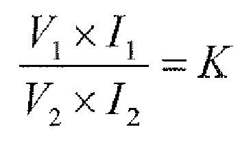
wherein the control module is configured to determine that the transformer has been incorrectly set if the value of 'K' is out of a predetermined range based on '1'. - The relay of one of claims 1 to 3, further comprising an output module configured to output a result of the determination to the outside.
- A transformer protecting method using a transformer protecting relay, the method comprising:receiving a voltage ratio of a transformer, and a current ratio between a primary current transformer and a secondary current transformer connected to the transformer; anddetermining whether the transformer has been correctly set or not based on the voltage ratio and the current ratio.
- The method of claim 5, wherein the step of determining whether the transformer has been correctly set or not includes:comparing a value obtained by multiplying the voltage ratio by the current ratio with a predetermined range;determining that the transformer has been correctly set if the value is within the predetermined range as a result of the comparison; anddetermining that the transformer has been incorrectly set if the value is out of the predetermined range as a result of the comparison.
- The method of claim 5 or 6, wherein the step of determining whether the transformer has been correctly set or not includes:calculating a value of 'K' based on a following formula,
 comparing the value of 'K' with a predetermined range;determining that the transformer has been correctly set if the value of 'K' is within the predetermined range; anddetermining that the transformer has been incorrectly set if the value of 'K' is out of the predetermined range.
 - The method of one of claims 5 to 7, further comprising outputting a result of the determination to the outside.
- A transformer protecting system, comprising:a transformer having a predetermined voltage ratio, and configured to convert a voltage of an input side power unit and to supply the converted voltage to an output side power unit;a primary current transformer and a secondary current transformer connected to an input side and an output side of the transformer, respectively;a user's setting receiving unit configured to receive the voltage ratio of the transformer and the current ratio between the primary current transformer and the secondary current transformer; anda relay configured to determine whether the transformer has been correctly set or not by a user, based on the voltage ratio and the current ratio.
- The transformer protecting system of claim 9, wherein the relay calculates a value of 'K' based on a following formula,

secondary voltage, I 1 is a primary current, and I 2 is a secondary current.), and
wherein the relay determines that the transformer has been incorrectly set if the value of 'K' is out of the predetermined range based on '1'. - The transformer protecting system of claim 9 or 10 further comprising an input side switch provided at the transformer and the primary current transformer, and configured to disconnect the transformer and the primary current transformer from each other according to a disconnection signal.
- The transformer protecting system of one of claims 9 to 11, further comprising an output side switch provided at the transformer and the secondary current transformer, and configured to disconnect the transformer and the secondary current transformer from each other according to a disconnection signal.
- The transformer protecting system of claim 11 or 12, wherein the relay is configured to generate the disconnection signal.
- The transformer protecting system of one of claims 9 to 13, wherein the relay is configured to inform a result of the determination to the outside.
Applications Claiming Priority (1)
| Application Number | Priority Date | Filing Date | Title |
|---|---|---|---|
| KR1020110008436A KR20120087013A (en) | 2011-01-27 | 2011-01-27 | Transformer protecting apparatus, protecting method thereof, and transformer protecting system including the same |
Publications (2)
| Publication Number | Publication Date |
|---|---|
| EP2482410A1 true EP2482410A1 (en) | 2012-08-01 |
| EP2482410B1 EP2482410B1 (en) | 2016-06-22 |
Family
ID=45655230
Family Applications (1)
| Application Number | Title | Priority Date | Filing Date |
|---|---|---|---|
| EP12152400.3A Not-in-force EP2482410B1 (en) | 2011-01-27 | 2012-01-25 | Relay and method for protecting transformer, and transformer protecting system having the same |
Country Status (6)
| Country | Link |
|---|---|
| US (1) | US8854776B2 (en) |
| EP (1) | EP2482410B1 (en) |
| JP (1) | JP2012157241A (en) |
| KR (1) | KR20120087013A (en) |
| CN (1) | CN102623958A (en) |
| ES (1) | ES2590707T3 (en) |
Families Citing this family (4)
| Publication number | Priority date | Publication date | Assignee | Title |
|---|---|---|---|---|
| RU2593380C1 (en) * | 2015-05-22 | 2016-08-10 | Роман Александрович Шестак | Device for offset from magnetisation current rush during connection under voltage for transformer differential protection |
| KR101770926B1 (en) | 2016-12-30 | 2017-08-23 | 엘에스산전 주식회사 | Method for detecting electrical disturbances by DC component |
| RU2639314C1 (en) * | 2017-02-27 | 2017-12-21 | Общество с ограниченной ответственностью Научно-производственное предприятие "ЭКРА" | Device of relay protection for local backup of auto-type transformer protections |
| JP7665273B2 (en) * | 2023-09-13 | 2025-04-21 | 大崎電気工業株式会社 | Computer program for detecting errors in transformer-related setting information stored in electronic watt-hour meters |
Citations (2)
| Publication number | Priority date | Publication date | Assignee | Title |
|---|---|---|---|---|
| JPH09284989A (en) * | 1996-04-12 | 1997-10-31 | Fuji Electric Co Ltd | Protective relay, method of predicting timing of zero residual magnetic flux, and protective relay system |
| JPH11308759A (en) * | 1998-04-24 | 1999-11-05 | Mitsubishi Electric Corp | Distance relay device |
Family Cites Families (12)
| Publication number | Priority date | Publication date | Assignee | Title |
|---|---|---|---|---|
| US2456541A (en) * | 1944-10-28 | 1948-12-14 | Bbc Brown Boveri & Cie | Differential relay |
| GB1400054A (en) * | 1971-09-24 | 1975-07-16 | Unisearch Ltd | Protection of transformers |
| JPS63265518A (en) | 1987-04-23 | 1988-11-02 | Fuji Electric Co Ltd | Ratio differential relay |
| JPH01157214A (en) | 1987-12-14 | 1989-06-20 | Toshiba Corp | Setting system for digital type protective relay |
| JPH01157215A (en) | 1987-12-14 | 1989-06-20 | Toshiba Corp | Setting system for digital type protective relay |
| FR2714771B1 (en) | 1994-01-06 | 1996-02-02 | Merlin Gerin | Differential protection device for a power transformer. |
| WO2002093710A1 (en) * | 2001-05-17 | 2002-11-21 | Yong-Cheol Kang | Relaying method for protecting a transformer using a difference of current |
| JP2004125688A (en) | 2002-10-04 | 2004-04-22 | Nippon Steel Corp | Field test method of differential relay using inrush current |
| JP2005269870A (en) | 2004-03-22 | 2005-09-29 | Mitsubishi Electric Corp | Ratio differential protector |
| US7738221B2 (en) * | 2007-12-07 | 2010-06-15 | Cooper Technologies Company | Transformer inrush current detector |
| US20110161468A1 (en) * | 2009-12-31 | 2011-06-30 | Schneider Electric USA, Inc. | Method and system for cascading peer-to-peer configuration of large systems of ieds |
| CN201682326U (en) * | 2010-03-10 | 2010-12-22 | 常州托特电子有限公司 | Intelligent power quality monitor terminal device |
-
2011
- 2011-01-27 KR KR1020110008436A patent/KR20120087013A/en not_active Ceased
-
2012
- 2012-01-19 US US13/354,253 patent/US8854776B2/en active Active
- 2012-01-25 EP EP12152400.3A patent/EP2482410B1/en not_active Not-in-force
- 2012-01-25 ES ES12152400.3T patent/ES2590707T3/en active Active
- 2012-01-26 JP JP2012014088A patent/JP2012157241A/en active Pending
- 2012-01-29 CN CN2012100427296A patent/CN102623958A/en active Pending
Patent Citations (2)
| Publication number | Priority date | Publication date | Assignee | Title |
|---|---|---|---|---|
| JPH09284989A (en) * | 1996-04-12 | 1997-10-31 | Fuji Electric Co Ltd | Protective relay, method of predicting timing of zero residual magnetic flux, and protective relay system |
| JPH11308759A (en) * | 1998-04-24 | 1999-11-05 | Mitsubishi Electric Corp | Distance relay device |
Non-Patent Citations (1)
| Title |
|---|
| "Differential Protection for Power Transformers with RET 670", PRODUKTÜBERBLICK TRANSFORMATORSCHUTZ RET670, 22 November 2006 (2006-11-22), Artikel Application Example, pages 1 - 14, XP055029996, Retrieved from the Internet <URL:http://www05.abb.com/global/scot/scot313.nsf/veritydisplay/37a6cf84ac1bca02c12572600034d00f/$file/SA2007-000029_-_en_Differential_protection_for_power_transformers_with_RET_670.pdf> [retrieved on 20120615] * |
Also Published As
| Publication number | Publication date |
|---|---|
| US20120194949A1 (en) | 2012-08-02 |
| KR20120087013A (en) | 2012-08-06 |
| JP2012157241A (en) | 2012-08-16 |
| US8854776B2 (en) | 2014-10-07 |
| ES2590707T3 (en) | 2016-11-23 |
| EP2482410B1 (en) | 2016-06-22 |
| CN102623958A (en) | 2012-08-01 |
Similar Documents
| Publication | Publication Date | Title |
|---|---|---|
| EP3232209B1 (en) | Insulation resistance measuring device and method | |
| US7924019B2 (en) | System and method for fault isolation and leakage current detection | |
| US7747879B2 (en) | Power distribution system using solid state power controllers | |
| US8854776B2 (en) | Relay and method for protecting transformer, and transformer protecting system having the same | |
| KR101273144B1 (en) | Over current relay for diagnosing open condition of current transformer secondary circuit and method thereof | |
| KR101365398B1 (en) | Earthquake disaster prevention system built-in switchgear and control method thereof | |
| JP6004514B2 (en) | Earth leakage detector | |
| US20200180463A1 (en) | Apparatus for controlling isolation charging of vehicle, system having the same, and method thereof | |
| CA2950737A1 (en) | Device and method for calculating stability and predicting error of power system network | |
| CN107110904B (en) | Grounding detection device for vehicle | |
| US9606169B2 (en) | Protection apparatus and method of verifying operation thereof | |
| KR20130141091A (en) | Electric leakage circuit breaker and method for controlling the same | |
| CN101420114A (en) | Multifunctional three phase power source protector | |
| EP2110917A2 (en) | Method of setting a ground fault trip function for a trip unit and a trip unit having a defined trip function for ground fault protection | |
| KR102612927B1 (en) | Failure diagnosis method of digital relay and apparatus performing the same | |
| JP6509029B2 (en) | Distribution board | |
| CN101950950A (en) | Self-checking protective device of motor before starting | |
| KR20220091058A (en) | Electric leakage detector with complex function | |
| KR101208468B1 (en) | Device for prevention disaster in cabinet panel | |
| JP7354358B2 (en) | adapter | |
| JP2015035865A (en) | Power converter | |
| JP2013110936A (en) | Transmission line automatic restoration system | |
| KR20140106240A (en) | System and method for measuring efficiency of voltage/current in power module | |
| JP6840426B2 (en) | Power monitoring system | |
| CN111416324A (en) | Residual current circuit breaker of type capable of outputting leakage current and control method thereof |
Legal Events
| Date | Code | Title | Description |
|---|---|---|---|
| PUAI | Public reference made under article 153(3) epc to a published international application that has entered the european phase |
Free format text: ORIGINAL CODE: 0009012 |
|
| AK | Designated contracting states |
Kind code of ref document: A1 Designated state(s): AL AT BE BG CH CY CZ DE DK EE ES FI FR GB GR HR HU IE IS IT LI LT LU LV MC MK MT NL NO PL PT RO RS SE SI SK SM TR |
|
| AX | Request for extension of the european patent |
Extension state: BA ME |
|
| 17P | Request for examination filed |
Effective date: 20130125 |
|
| 17Q | First examination report despatched |
Effective date: 20130716 |
|
| GRAP | Despatch of communication of intention to grant a patent |
Free format text: ORIGINAL CODE: EPIDOSNIGR1 |
|
| INTG | Intention to grant announced |
Effective date: 20160315 |
|
| GRAS | Grant fee paid |
Free format text: ORIGINAL CODE: EPIDOSNIGR3 |
|
| GRAA | (expected) grant |
Free format text: ORIGINAL CODE: 0009210 |
|
| AK | Designated contracting states |
Kind code of ref document: B1 Designated state(s): AL AT BE BG CH CY CZ DE DK EE ES FI FR GB GR HR HU IE IS IT LI LT LU LV MC MK MT NL NO PL PT RO RS SE SI SK SM TR |
|
| REG | Reference to a national code |
Ref country code: GB Ref legal event code: FG4D |
|
| REG | Reference to a national code |
Ref country code: CH Ref legal event code: EP |
|
| REG | Reference to a national code |
Ref country code: IE Ref legal event code: FG4D |
|
| REG | Reference to a national code |
Ref country code: AT Ref legal event code: REF Ref document number: 808161 Country of ref document: AT Kind code of ref document: T Effective date: 20160715 |
|
| REG | Reference to a national code |
Ref country code: DE Ref legal event code: R096 Ref document number: 602012019666 Country of ref document: DE |
|
| REG | Reference to a national code |
Ref country code: LT Ref legal event code: MG4D |
|
| REG | Reference to a national code |
Ref country code: NL Ref legal event code: MP Effective date: 20160622 |
|
| PG25 | Lapsed in a contracting state [announced via postgrant information from national office to epo] |
Ref country code: NO Free format text: LAPSE BECAUSE OF FAILURE TO SUBMIT A TRANSLATION OF THE DESCRIPTION OR TO PAY THE FEE WITHIN THE PRESCRIBED TIME-LIMIT Effective date: 20160922 Ref country code: FI Free format text: LAPSE BECAUSE OF FAILURE TO SUBMIT A TRANSLATION OF THE DESCRIPTION OR TO PAY THE FEE WITHIN THE PRESCRIBED TIME-LIMIT Effective date: 20160622 Ref country code: LT Free format text: LAPSE BECAUSE OF FAILURE TO SUBMIT A TRANSLATION OF THE DESCRIPTION OR TO PAY THE FEE WITHIN THE PRESCRIBED TIME-LIMIT Effective date: 20160622 |
|
| REG | Reference to a national code |
Ref country code: AT Ref legal event code: MK05 Ref document number: 808161 Country of ref document: AT Kind code of ref document: T Effective date: 20160622 |
|
| REG | Reference to a national code |
Ref country code: ES Ref legal event code: FG2A Ref document number: 2590707 Country of ref document: ES Kind code of ref document: T3 Effective date: 20161123 |
|
| PG25 | Lapsed in a contracting state [announced via postgrant information from national office to epo] |
Ref country code: GR Free format text: LAPSE BECAUSE OF FAILURE TO SUBMIT A TRANSLATION OF THE DESCRIPTION OR TO PAY THE FEE WITHIN THE PRESCRIBED TIME-LIMIT Effective date: 20160923 Ref country code: SE Free format text: LAPSE BECAUSE OF FAILURE TO SUBMIT A TRANSLATION OF THE DESCRIPTION OR TO PAY THE FEE WITHIN THE PRESCRIBED TIME-LIMIT Effective date: 20160622 Ref country code: HR Free format text: LAPSE BECAUSE OF FAILURE TO SUBMIT A TRANSLATION OF THE DESCRIPTION OR TO PAY THE FEE WITHIN THE PRESCRIBED TIME-LIMIT Effective date: 20160622 Ref country code: LV Free format text: LAPSE BECAUSE OF FAILURE TO SUBMIT A TRANSLATION OF THE DESCRIPTION OR TO PAY THE FEE WITHIN THE PRESCRIBED TIME-LIMIT Effective date: 20160622 Ref country code: NL Free format text: LAPSE BECAUSE OF FAILURE TO SUBMIT A TRANSLATION OF THE DESCRIPTION OR TO PAY THE FEE WITHIN THE PRESCRIBED TIME-LIMIT Effective date: 20160622 Ref country code: RS Free format text: LAPSE BECAUSE OF FAILURE TO SUBMIT A TRANSLATION OF THE DESCRIPTION OR TO PAY THE FEE WITHIN THE PRESCRIBED TIME-LIMIT Effective date: 20160622 |
|
| REG | Reference to a national code |
Ref country code: FR Ref legal event code: PLFP Year of fee payment: 6 |
|
| PG25 | Lapsed in a contracting state [announced via postgrant information from national office to epo] |
Ref country code: SK Free format text: LAPSE BECAUSE OF FAILURE TO SUBMIT A TRANSLATION OF THE DESCRIPTION OR TO PAY THE FEE WITHIN THE PRESCRIBED TIME-LIMIT Effective date: 20160622 Ref country code: IS Free format text: LAPSE BECAUSE OF FAILURE TO SUBMIT A TRANSLATION OF THE DESCRIPTION OR TO PAY THE FEE WITHIN THE PRESCRIBED TIME-LIMIT Effective date: 20161022 Ref country code: RO Free format text: LAPSE BECAUSE OF FAILURE TO SUBMIT A TRANSLATION OF THE DESCRIPTION OR TO PAY THE FEE WITHIN THE PRESCRIBED TIME-LIMIT Effective date: 20160622 Ref country code: CZ Free format text: LAPSE BECAUSE OF FAILURE TO SUBMIT A TRANSLATION OF THE DESCRIPTION OR TO PAY THE FEE WITHIN THE PRESCRIBED TIME-LIMIT Effective date: 20160622 Ref country code: EE Free format text: LAPSE BECAUSE OF FAILURE TO SUBMIT A TRANSLATION OF THE DESCRIPTION OR TO PAY THE FEE WITHIN THE PRESCRIBED TIME-LIMIT Effective date: 20160622 |
|
| PG25 | Lapsed in a contracting state [announced via postgrant information from national office to epo] |
Ref country code: SM Free format text: LAPSE BECAUSE OF FAILURE TO SUBMIT A TRANSLATION OF THE DESCRIPTION OR TO PAY THE FEE WITHIN THE PRESCRIBED TIME-LIMIT Effective date: 20160622 Ref country code: AT Free format text: LAPSE BECAUSE OF FAILURE TO SUBMIT A TRANSLATION OF THE DESCRIPTION OR TO PAY THE FEE WITHIN THE PRESCRIBED TIME-LIMIT Effective date: 20160622 Ref country code: PT Free format text: LAPSE BECAUSE OF FAILURE TO SUBMIT A TRANSLATION OF THE DESCRIPTION OR TO PAY THE FEE WITHIN THE PRESCRIBED TIME-LIMIT Effective date: 20161024 Ref country code: PL Free format text: LAPSE BECAUSE OF FAILURE TO SUBMIT A TRANSLATION OF THE DESCRIPTION OR TO PAY THE FEE WITHIN THE PRESCRIBED TIME-LIMIT Effective date: 20160622 Ref country code: BE Free format text: LAPSE BECAUSE OF FAILURE TO SUBMIT A TRANSLATION OF THE DESCRIPTION OR TO PAY THE FEE WITHIN THE PRESCRIBED TIME-LIMIT Effective date: 20160622 |
|
| REG | Reference to a national code |
Ref country code: DE Ref legal event code: R097 Ref document number: 602012019666 Country of ref document: DE |
|
| PLBE | No opposition filed within time limit |
Free format text: ORIGINAL CODE: 0009261 |
|
| STAA | Information on the status of an ep patent application or granted ep patent |
Free format text: STATUS: NO OPPOSITION FILED WITHIN TIME LIMIT |
|
| 26N | No opposition filed |
Effective date: 20170323 |
|
| PG25 | Lapsed in a contracting state [announced via postgrant information from national office to epo] |
Ref country code: DK Free format text: LAPSE BECAUSE OF FAILURE TO SUBMIT A TRANSLATION OF THE DESCRIPTION OR TO PAY THE FEE WITHIN THE PRESCRIBED TIME-LIMIT Effective date: 20160622 |
|
| PG25 | Lapsed in a contracting state [announced via postgrant information from national office to epo] |
Ref country code: SI Free format text: LAPSE BECAUSE OF FAILURE TO SUBMIT A TRANSLATION OF THE DESCRIPTION OR TO PAY THE FEE WITHIN THE PRESCRIBED TIME-LIMIT Effective date: 20160622 |
|
| REG | Reference to a national code |
Ref country code: CH Ref legal event code: PL |
|
| PG25 | Lapsed in a contracting state [announced via postgrant information from national office to epo] |
Ref country code: MC Free format text: LAPSE BECAUSE OF FAILURE TO SUBMIT A TRANSLATION OF THE DESCRIPTION OR TO PAY THE FEE WITHIN THE PRESCRIBED TIME-LIMIT Effective date: 20160622 |
|
| PG25 | Lapsed in a contracting state [announced via postgrant information from national office to epo] |
Ref country code: CH Free format text: LAPSE BECAUSE OF NON-PAYMENT OF DUE FEES Effective date: 20170131 Ref country code: LI Free format text: LAPSE BECAUSE OF NON-PAYMENT OF DUE FEES Effective date: 20170131 |
|
| REG | Reference to a national code |
Ref country code: IE Ref legal event code: MM4A |
|
| PG25 | Lapsed in a contracting state [announced via postgrant information from national office to epo] |
Ref country code: LU Free format text: LAPSE BECAUSE OF NON-PAYMENT OF DUE FEES Effective date: 20170125 |
|
| REG | Reference to a national code |
Ref country code: FR Ref legal event code: PLFP Year of fee payment: 7 |
|
| PG25 | Lapsed in a contracting state [announced via postgrant information from national office to epo] |
Ref country code: IE Free format text: LAPSE BECAUSE OF NON-PAYMENT OF DUE FEES Effective date: 20170125 |
|
| PG25 | Lapsed in a contracting state [announced via postgrant information from national office to epo] |
Ref country code: MT Free format text: LAPSE BECAUSE OF NON-PAYMENT OF DUE FEES Effective date: 20170125 |
|
| PG25 | Lapsed in a contracting state [announced via postgrant information from national office to epo] |
Ref country code: AL Free format text: LAPSE BECAUSE OF FAILURE TO SUBMIT A TRANSLATION OF THE DESCRIPTION OR TO PAY THE FEE WITHIN THE PRESCRIBED TIME-LIMIT Effective date: 20160622 |
|
| PG25 | Lapsed in a contracting state [announced via postgrant information from national office to epo] |
Ref country code: HU Free format text: LAPSE BECAUSE OF FAILURE TO SUBMIT A TRANSLATION OF THE DESCRIPTION OR TO PAY THE FEE WITHIN THE PRESCRIBED TIME-LIMIT; INVALID AB INITIO Effective date: 20120125 |
|
| PG25 | Lapsed in a contracting state [announced via postgrant information from national office to epo] |
Ref country code: BG Free format text: LAPSE BECAUSE OF FAILURE TO SUBMIT A TRANSLATION OF THE DESCRIPTION OR TO PAY THE FEE WITHIN THE PRESCRIBED TIME-LIMIT Effective date: 20160622 |
|
| PG25 | Lapsed in a contracting state [announced via postgrant information from national office to epo] |
Ref country code: CY Free format text: LAPSE BECAUSE OF NON-PAYMENT OF DUE FEES Effective date: 20160622 |
|
| PG25 | Lapsed in a contracting state [announced via postgrant information from national office to epo] |
Ref country code: MK Free format text: LAPSE BECAUSE OF FAILURE TO SUBMIT A TRANSLATION OF THE DESCRIPTION OR TO PAY THE FEE WITHIN THE PRESCRIBED TIME-LIMIT Effective date: 20160622 |
|
| PGFP | Annual fee paid to national office [announced via postgrant information from national office to epo] |
Ref country code: FR Payment date: 20191223 Year of fee payment: 9 |
|
| PG25 | Lapsed in a contracting state [announced via postgrant information from national office to epo] |
Ref country code: TR Free format text: LAPSE BECAUSE OF FAILURE TO SUBMIT A TRANSLATION OF THE DESCRIPTION OR TO PAY THE FEE WITHIN THE PRESCRIBED TIME-LIMIT Effective date: 20160622 |
|
| PGFP | Annual fee paid to national office [announced via postgrant information from national office to epo] |
Ref country code: ES Payment date: 20200207 Year of fee payment: 9 Ref country code: IT Payment date: 20200114 Year of fee payment: 9 Ref country code: DE Payment date: 20191220 Year of fee payment: 9 Ref country code: GB Payment date: 20191223 Year of fee payment: 9 |
|
| REG | Reference to a national code |
Ref country code: DE Ref legal event code: R119 Ref document number: 602012019666 Country of ref document: DE |
|
| GBPC | Gb: european patent ceased through non-payment of renewal fee |
Effective date: 20210125 |
|
| PG25 | Lapsed in a contracting state [announced via postgrant information from national office to epo] |
Ref country code: FR Free format text: LAPSE BECAUSE OF NON-PAYMENT OF DUE FEES Effective date: 20210131 |
|
| PG25 | Lapsed in a contracting state [announced via postgrant information from national office to epo] |
Ref country code: DE Free format text: LAPSE BECAUSE OF NON-PAYMENT OF DUE FEES Effective date: 20210803 Ref country code: GB Free format text: LAPSE BECAUSE OF NON-PAYMENT OF DUE FEES Effective date: 20210125 |
|
| REG | Reference to a national code |
Ref country code: ES Ref legal event code: FD2A Effective date: 20220427 |
|
| PG25 | Lapsed in a contracting state [announced via postgrant information from national office to epo] |
Ref country code: IT Free format text: LAPSE BECAUSE OF NON-PAYMENT OF DUE FEES Effective date: 20210125 |
|
| PG25 | Lapsed in a contracting state [announced via postgrant information from national office to epo] |
Ref country code: ES Free format text: LAPSE BECAUSE OF NON-PAYMENT OF DUE FEES Effective date: 20210126 |