EP2482378A1 - Deployable antenna - Google Patents
Deployable antenna Download PDFInfo
- Publication number
- EP2482378A1 EP2482378A1 EP20120152827 EP12152827A EP2482378A1 EP 2482378 A1 EP2482378 A1 EP 2482378A1 EP 20120152827 EP20120152827 EP 20120152827 EP 12152827 A EP12152827 A EP 12152827A EP 2482378 A1 EP2482378 A1 EP 2482378A1
- Authority
- EP
- European Patent Office
- Prior art keywords
- link
- side link
- deployment
- slider
- deployable antenna
- Prior art date
- Legal status (The legal status is an assumption and is not a legal conclusion. Google has not performed a legal analysis and makes no representation as to the accuracy of the status listed.)
- Granted
Links
Images




Classifications
-
- H—ELECTRICITY
- H01—ELECTRIC ELEMENTS
- H01Q—ANTENNAS, i.e. RADIO AERIALS
- H01Q15/00—Devices for reflection, refraction, diffraction or polarisation of waves radiated from an antenna, e.g. quasi-optical devices
- H01Q15/14—Reflecting surfaces; Equivalent structures
- H01Q15/16—Reflecting surfaces; Equivalent structures curved in two dimensions [2D], e.g. paraboloidal
- H01Q15/161—Collapsible reflectors
-
- H—ELECTRICITY
- H01—ELECTRIC ELEMENTS
- H01Q—ANTENNAS, i.e. RADIO AERIALS
- H01Q1/00—Details of, or arrangements associated with, antennas
- H01Q1/27—Adaptation for use in or on movable bodies
- H01Q1/28—Adaptation for use in or on aircraft, missiles, satellites, or balloons
- H01Q1/288—Satellite antennas
Definitions
- This invention relates to a deployable antenna.
- the deployable antenna is transported in a folded state because of its limited stowage capacity during the transportation from ground to orbit. After transported to the orbit, the deployable antenna in the folded state is deployed as an antenna in the orbit.
- FIGS. 1 , 2 , and 3 are illustrations of a deployable antenna A0 according to the related art.
- FIG. 1 is a view of the deployable antenna A0 as obliquely viewed to its front surface.
- FIG. 2 is a view of the deployable antenna A0 as obliquely viewed to its back surface.
- FIG. 3 is a view illustrating the back surface of the deployable antenna A0.
- the deployable antenna A0 is a large deployable antenna having an aperture diameter size exceeding 10 m.
- a plurality of deployable antenna modules A1 FIG. 1
- joint members 40 FIG. 3
- deployment driving mechanisms 30 FIGS. 2 and 3
- FIGS. 2 and 3 deployment driving mechanisms 30 are provided to the respective deployable antenna modules A1, resulting in an increase in number of the deployment driving mechanisms 30 to be used, which are hard to reduce in weight. Consequently, there is a disadvantage that the mass of the deployable antenna A0 increases.
- each deployable antenna module A1 is smaller than the aperture diameter size of the deployable antenna A0. Therefore, in order to obtain the deployable antenna A0 having a large aperture diameter, a plurality of deployable antenna modules A1 need to be jointed to one another to increase the area of the antenna.
- the number of the deployment driving mechanisms 30 to be used for the deployable antenna A0 increases, which leads to the disadvantage that the mass of the entire antenna increases.
- JP-A No. 2006-80577 discloses, in FIG. 3 and paragraphs [0024] and [0025], that each frame 2 is constructed of five planar links 3, and that the adjacent planar links 3 are jointed to each other in a mirror-image relationship.
- JP-A No. 2006-80577 discloses, in FIG. 4 and paragraphs [0026], [0028] to [0031], and [0033], that the slide hinge 7 of each planar link 3 is moved by the wire driving device (extending means) 11 (corresponding to the deployment driving mechanism described above) to fold and unfold the frame 2.
- each planar link 3 is provided with the slide hinge 7, but the linkmember 4a opposed to the link member 4c is not provided with any slider for synchronized unfolding between the two adjacent planar links.
- each planar link 3 is provided with the slide hinge 7, but the linkmember 4a opposed to the linkmember 4c is not provided with any slider for synchronized unfolding between the two adjacent planar links.
- JP-A Japanese Unexamined Patent Application Publication
- Hei 11-112228 discloses, in FIGS. 1 and 2 and paragraph [0025], the planar truss 1 in a state of being unfolded into a rectangular shape.
- Japanese Unexamined Patent Application Publication (JP-A) No. 2003-95199 discloses, in FIGS. 1 (a) and 1 (b), FIG. 2 , and paragraph [0019], the deployable antenna in which the bone members 14 each having two four-node links 12 and 13 continuously connected together are disposed around the central vertical beam member 11.
- the synchronization mechanism 19 serving as unfolding synchronization means is provided to the central vertical beam member 11 so as to be movable in the axial direction thereof.
- One end of the synchronization cable 20 is fixed to the synchronization mechanism 19, and the other end of the synchronization cable 20 is fixed in the vicinity of the hinge of the inclined member 123 of the four-node link 12 of the bone member 14 under a state in which the synchronization cable 20 is looped around the guide pulley 201.
- both the vertical beam member 122 opposed to the central vertical beammember 11 and the vertical beam member 132 opposed to the vertical beam member 122 are not provided with any slider similarly to Japanese Unexamined Patent Application Publication (JP-A) No. 2006-80577 and International Patent W02005/027186A .
- a deployable antenna including:
- a deployable antenna including:
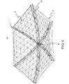
- FIG. 4 is an illustration of a deployable antenna A1' according to a first embodiment of this invention.
- the deployable antenna A1' alone may serve as a large deployable antenna corresponding to the large deployable antenna A0 illustrated in FIGS. 1 to 3 .
- the deployable antenna A1' is stowed in a folded state inside a fairing of a launch vehicle, and is deployed in orbit to form an antenna reflector mirror surface (flexible reflector mirror surface 4), which is formed of a flexible film surface, into a predetermined parabolic shape.
- the deployable antenna A1' includes the flexible reflector mirror surface 4, an antenna deploying mechanism 1 that supports an outer edge portion of the flexible reflector mirror surface 4, and bands 3.
- the flexible reflector mirror surface 4 serves as a front surface of the deployable antenna A1'.
- FIG. 5 is an illustration of the antenna deploying mechanism 1 of the deployable antenna A1' illustrated in FIG. 4 .
- the antenna deploying mechanism 1 includes six deployment link mechanisms 20 arranged radially from a central shaft of the antenna deploying mechanism 1 so as to support the outer edge portion of the flexible reflector mirror surface 4 at six points, and one deployment driving mechanism 30 arranged at a lower portion of the center of arrangement of the six deployment link mechanisms 20.
- the deployment driving mechanism 30 is an actuator mechanism part for unfolding the six deployment link mechanisms 20.
- the bands 3 illustrated in FIG. 4 are provided so as to adjust a phase angle of each deployment linkmechanism 20.
- FIG. 6 is an illustration of a single deployment link mechanism 20 that is a component of the six deployment link mechanisms 20 of the antenna deploying mechanism 1 illustrated in FIG. 5 .
- the single deployment linkmechanism20 includes three four-side links 5, 6, and 7 arranged in an order from the position of the central shaft, around which the six deployment link mechanisms 20 are arranged, toward an outer side of the deployment link mechanism 20.
- the deployment linkmechanism20 is structuredtobe foldable in three stages.
- black spots represent hinge mechanisms.
- Each deployable antenna module A1 of the deployable antenna A0 illustrated as the related art in FIGS. 1 to 3 has an antenna deploying mechanism similar to the antenna deploying mechanism 1 illustrated in FIG. 5 .
- the antenna deploying mechanism of the deployable antenna module A1 also includes six radially arranged deployment link mechanisms 20 and one deployment driving mechanism 30.
- the deployment link mechanisms 20 of the deployable antenna module A1 are each constructed of the four-side link 7 alone (single stage).
- the deployment link mechanism 20 is constructed of the four-side links 5, 6, and 7 (three stages: foldable in three stages).
- the four-side link 6 is jointed to the four-side link 5 serving as a support structure for the deployable antenna A1', the four-side link 6 having a shape line-symmetric to that of the four-side link 5.
- the four-side link 7 is jointed to the four-side link 6, the four-side link 7 having a shape line-symmetric to that of the four-side link 6.
- the three-fold structure is employed to increase an aperture diameter size of the single deployable antenna A1'.
- the single deployable antenna A1' is structured to have an aperture diameter size that is substantially three times as large as the module aperture diameter size of the single deployable antenna module A1 ( FIGS. 1 to 3 ).
- the deployable antenna A1' alone may serve as a large deployable antenna corresponding to the large deployable antenna A0 illustrated in FIGS. 1 to 3 .
- FIG. 7 is an illustration of the four-side link 5 situated at the left end of the deployment link mechanism 20 illustrated in FIG. 6 .
- the four-side link 5 is constructed of the link member 8 and link members 13, 14, and 15. To the four-side link 5, the slider 9, link members 10, 11, and 12, the slider 16, and a link member 17 are jointed through hinge mechanisms hg.
- the deployment driving mechanism 30 causes the slider 9 to slide upwardly along the central vertical link member 8 serving as the central shaft. Accordingly, the linkmember 10 brings the linkmembers 11 and 12 into an extended state, to thereby unfold the four-side link 5.
- the unfolded four-side link 5 causes the slider 16 to slide upwardly along the common vertical link member 15, and accordingly the four-side link 6 is unfolded by the link member 17. In this manner, the unfolded shape of the four-side link 6 is synchronized with the unfolded shape of the four-side link 5.
- the unfolded four-side link 6 causes the slider 9 to slide upwardly along the another common vertical link member 8. Accordingly, the link member 10 brings the link members 11 and 12 into an extended state, to thereby unfold the four-side link 7. In this manner, the unfolded shape of the four-side link 7 is synchronized with the unfolded shape of the four-side link 6.
- FIG. 8 is an illustration of a right end portion of the four-side link 5 situated at the left end of FIG. 6 and a left end portion of the four-side link 6 situated at the center of FIG. 6 .
- the slider 16 moves vertically along the common vertical link member 15.
- One end of the link member 17 is rotatably fixed to the link member 14, and the other end of the link member 17 is rotatably fixed to the slider 16.
- FIG. 9 is an illustration of a left end portion of the four-side link 5 situated at the left end of FIGS. 6 and 7 .
- FIG. 10 is an illustration of a right end portion of the four-side link 7 situated at the right end of FIG. 6 .
- FIG. 11 is an illustration of the deployment driving mechanism 30 of FIG. 6 .
- the deployment driving mechanism 30 includes an actuator 31 (for example, a spring) for pushing the slider 9 up in the unfolding direction (that is, upwardly along the central vertical link member 8), and a damping device 32 (for example, a wire to be driven by a motor) for controlling the unfolding motion of the slider 9. Further, the four-side link may be folded when the damping device 32 is moved in a reverse direction.
- an actuator 31 for example, a spring
- a damping device 32 for example, a wire to be driven by a motor
- the deployment driving mechanism 30 causes the slider 9 to slide upwardly along the central vertical link member 8. Accordingly, the linkmember 10 brings the link members 11 and 12 into an extended state, to thereby unfold the four-side link 5 constructed of the link members 8, 13, 14, and 15.
- the link members 11 and 12 in the extended state serve as a structure for stably maintaining the shape of the four-side link 5 in the unfolded state.
- the unfolding force to be imparted by the slider 16 promotes the unfolding force to be imparted by the slider 9, and accordingly promotes the unfolding force of the entire deployment link mechanism 20.
- the four-side link 6 is line-symmetric to the four-side link 5, and hence unfolded line-symmetrically to the four-side link 5.
- the four-side link 7 is unfolded line-symmetrically to the four-side link 6.
- the deployment link mechanism 20 constructed of the four-side links 5, 6, and 7 is unfolded and folded in accordance with the slidingmotion of the sliders 9 and 16.
- the deployment link mechanisms 20 foldable in three stages are used to provide a mechanism capable of folding and unfolding the deployable antenna A1' having a large aperture diameter.
- the first embodiment enables the single deployable antenna A1' to serve as a large deployable antenna, to thereby reduce the weight of the large deployable antenna.
- the outermost peripheral portions of a plurality of deployable antennas A1' (outermost peripheral portions of four-side links 7) only need to be jointed to one another by a plurality of joint members 40 ( FIG. 3 ) to construct a jointed-type deployable antenna having a large aperture diameter size.
- FIG. 12 is an illustration of a deployment link mechanism 20' to be used in a deployable antenna according to a second embodiment of this invention.
- the deployment link mechanism 20' is constructed of five four-side links 5, 6, 5, 6, and 7, to thereby provide a deployment link mechanism foldable in five stages.
- the deployment link mechanism 20' is obtained by adding two four-side links 5 and 6 between the four-side links 6 and 7 of the deployment link mechanism 20 of FIG. 6 .
- the two added four-side links 5 and 6 have substantially the same structures as the four-side links 5 and 6 of the deployment link mechanism 20 of FIG. 6 .
- the five-fold structure is employed to increase the aperture diameter size of the deployable antenna.
- the deployable antenna is structured to have an aperture diameter size that is substantially five times as large as the module aperture diameter size of the deployable antenna module A1 ( FIGS. 1 to 3 ).
- the deployable antenna alone may also serve as a large deployable antenna corresponding to the large deployable antenna A0 illustrated in FIGS. 1 to 3 .
- the outermost peripheral portions of a plurality of deployable antennas (outermost peripheral portions of four-side links 7) only need to be jointed to one another by a plurality of joint members 40 ( FIG. 3 ) to construct a jointed-type deployable antenna having a large aperture diameter size.
- FIGS. 4 to 7 and 12 various structures of the deployable antenna according to the first and second embodiments are summarized in the following items (1) to (7):
- This invention is applicable to a folding mechanism of a deployable antenna, of the parabolic antennas to be mounted onto an artificial satellite or the like.
Landscapes
- Physics & Mathematics (AREA)
- Engineering & Computer Science (AREA)
- Astronomy & Astrophysics (AREA)
- General Physics & Mathematics (AREA)
- Remote Sensing (AREA)
- Aviation & Aerospace Engineering (AREA)
- Electromagnetism (AREA)
- Aerials With Secondary Devices (AREA)
- Details Of Aerials (AREA)
Abstract
Description
- This application is based upon and claims the benefit of priority from Japanese patent application No.
2011-017529, filed on January 31, 2011 - This invention relates to a deployable antenna.
- The deployable antenna is transported in a folded state because of its limited stowage capacity during the transportation from ground to orbit. After transported to the orbit, the deployable antenna in the folded state is deployed as an antenna in the orbit.
-
FIGS. 1 ,2 , and3 are illustrations of a deployable antenna A0 according to the related art.FIG. 1 is a view of the deployable antenna A0 as obliquely viewed to its front surface.FIG. 2 is a view of the deployable antenna A0 as obliquely viewed to its back surface.FIG. 3 is a view illustrating the back surface of the deployable antenna A0. - The deployable antenna A0 is a large deployable antenna having an aperture diameter size exceeding 10 m. In the deployable antenna A0 illustrated in the figures, a plurality of deployable antenna modules A1 (
FIG. 1 ) are jointed to and driven in association with one another by joint members 40 (FIG. 3 ), to thereby attain the deployable antenna having a large aperture diameter. In the deployable antenna A0 illustrated in the figures, deployment driving mechanisms 30 (FIGS. 2 and3 ) are provided to the respective deployable antenna modules A1, resulting in an increase in number of thedeployment driving mechanisms 30 to be used, which are hard to reduce in weight. Consequently, there is a disadvantage that the mass of the deployable antenna A0 increases. - As described above, the module diameter size of each deployable antenna module A1 is smaller than the aperture diameter size of the deployable antenna A0. Therefore, in order to obtain the deployable antenna A0 having a large aperture diameter, a plurality of deployable antenna modules A1 need to be jointed to one another to increase the area of the antenna. However, in the method of jointing a plurality of deployable antenna modules A1 to one another to attain the deployable antenna A0, the number of the
deployment driving mechanisms 30 to be used for the deployable antenna A0 increases, which leads to the disadvantage that the mass of the entire antenna increases. - Japanese Unexamined Patent Application Publication (JP-A) No.
2006-80577 FIG. 3 and paragraphs [0024] and [0025], that each frame 2 is constructed of fiveplanar links 3, and that the adjacentplanar links 3 are jointed to each other in a mirror-image relationship. - Further, Japanese Unexamined Patent Application Publication (JP-A) No.
2006-80577 FIG. 4 and paragraphs [0026], [0028] to [0031], and [0033], that theslide hinge 7 of eachplanar link 3 is moved by the wire driving device (extending means) 11 (corresponding to the deployment driving mechanism described above) to fold and unfold the frame 2. - However, as illustrated in
FIG. 4 of Japanese Unexamined Patent Application Publication (JP-A) No.2006-80577 planar link 3 is provided with theslide hinge 7, but the linkmember 4a opposed to the link member 4c is not provided with any slider for synchronized unfolding between the two adjacent planar links. - International Patent
W02005/027186A discloses, inFIG. 2 and lines 21 to 24 ofpage 7, that each frame 2 is constructed of fiveplanar links 3, and that the adjacentplanar links 3 are jointed to each other in a mirror-image relationship. - Further, International Patent
W02005/027186A discloses, inFIG. 3 ,lines 31 to 42 ofpage 7, and lines 48 to 50 ofpage 7, that theslide hinge 7 of eachplanar link 3 is moved by the wire driving device (extending means) 11 (corresponding to the deployment driving mechanism described above) to fold and unfold the frame 2. - However, as illustrated in
FIG. 3 of International PatentW02005/027186A , the link member 4c of eachplanar link 3 is provided with theslide hinge 7, but the linkmember 4a opposed to the linkmember 4c is not provided with any slider for synchronized unfolding between the two adjacent planar links. - Japanese Unexamined Patent Application Publication (JP-A) No.
Hei 11-112228 FIGS. 1 and2 and paragraph [0025], theplanar truss 1 in a state of being unfolded into a rectangular shape. - However, as illustrated in
FIG. 2 of Japanese Unexamined Patent Application Publication (JP-A) No.Hei 11-112228 planar truss 1 is provided with the slider 27, but the peripheral member 22 opposed to the central member 21 is not provided with any slider similarly to Japanese Unexamined Patent Application Publication (JP-A) No.2006-80577 W02005/027186A . - Japanese Unexamined Patent Application Publication (JP-A) No.
2003-95199 FIG. 2 , and paragraph [0019], the deployable antenna in which thebone members 14 each having two four-node links vertical beam member 11. As illustrated inFIG. 4 of Japanese Unexamined Patent Application Publication (JP-A) No.2003-95199 vertical beam member 11 so as to be movable in the axial direction thereof. One end of thesynchronization cable 20 is fixed to the synchronization mechanism 19, and the other end of thesynchronization cable 20 is fixed in the vicinity of the hinge of the inclined member 123 of the four-node link 12 of thebone member 14 under a state in which thesynchronization cable 20 is looped around the guide pulley 201. - However, both the vertical beam member 122 opposed to the central
vertical beammember 11 and the vertical beam member 132 opposed to the vertical beam member 122 are not provided with any slider similarly to Japanese Unexamined Patent Application Publication (JP-A) No.2006-80577 W02005/027186A . - It is an object of this invention to provide a deployable antenna having a larger aperture diameter by four-side links provided in a plurality of stages.
- According to this invention, it is possible to obtain a deployable antenna, including:
- six deployment link mechanisms arranged radially from a central shaft of the deployable antenna so as to support an outer edge portion of a flexible reflector mirror surface of the deployable antenna; and
- one deployment driving mechanism arranged at a lower portion of a center of arrangement of the six deployment link mechanisms, for unfolding the six deployment link mechanisms,
- in which each of the six deployment link mechanisms includes a first four-side link, a second four-side link, and a third four-side link arranged in an order from a position of the central shaft, around which the six deployment link mechanisms are arranged, toward an outer side of the each of the six deployment link mechanisms so that the each of the six deployment link mechanisms is structured to be foldable in three stages,
- in which a central vertical link member of the first four-side link, which serves as the central shaft, includes a first slider,
- in which a common vertical link member between the first four-side link and the second four-side link includes a second slider,
- in which another common vertical link member between the second four-side link and the third four-side link includes a third slider,
- in which the one deployment driving mechanism causes the first slider to slide upwardly along the central vertical link member, to thereby unfold the first four-side link,
- in which the unfolded first four-side link causes the second slider to slide upwardly along the common vertical link member, to thereby unfold the second four-side link, and
- in which the unfolded second four-side link causes the third slider to slide upwardly along the another common vertical link member, to thereby unfold the third four-side link.
- Further, according to this invention, it is possible to obtain a deployable antenna, including:
- eight deployment link mechanisms arranged radially from a central shaft of the deployable antenna so as to support an outer edge portion of a flexible reflector mirror surface of the deployable antenna; and
- one deployment driving mechanism arranged at a lower portion of a center of arrangement of the eight deployment link mechanisms, for unfolding the eight deployment link mechanisms,
- in which each of the eight deployment link mechanisms includes a first four-side link, a second four-side link, and a third four-side link arranged in an order from a position of the central shaft, around which the eight deployment link mechanisms are arranged, toward an outer side of the each of the eight deployment link mechanisms so that the each of the eight deployment link mechanisms is structured to be foldable in three stages,
- in which a central vertical link member of the first four-side link, which serves as the central shaft, includes a first slider,
- in which a common vertical link member between the first four-side link and the second four-side link includes a second slider,
- in which another common vertical link member between the second four-side link and the third four-side link includes a third slider,
- in which the one deployment driving mechanism causes the first slider to slide upwardly along the central vertical link member, to thereby unfold the first four-side link,
- in which the unfolded first four-side link causes the second slider to slide upwardly along the common vertical link member, to thereby unfold the second four-side link, and
- in which the unfolded second four-side link causes the third slider to slide upwardly along the another common vertical link member, to thereby unfold the third four-side link.
- According to this invention, it is possible to obtain the deployable antenna having a larger aperture diameter by the four-side links provided in the plurality of stages.
- In the accompanying drawings:
-
FIG. 1 is a view of a deployable antenna according to the related art as obliquely viewed to its front surface; -
FIG. 2 is a view of the deployable antenna illustrated inFIG. 1 as obliquely viewed to its back surface; -
FIG. 3 is a view illustrating the back surface of the deployable antenna illustrated inFIG. 1 ; -
FIG. 4 is a perspective view of a deployable antenna according to a first embodiment of this invention; -
FIG. 5 is a perspective view of an antenna deploying mechanism of the deployable antenna illustrated inFIG. 4 ; -
FIG. 6 is a view illustrating a deployment link mechanism of the antenna deploying mechanism illustrated inFIG. 5 ; -
FIG. 7 is a view illustrating a four-side link situated at a left end of the deployment link mechanism illustrated inFIG. 6 ; -
FIG. 8 is a view illustrating a right end portion of the four-side link situated at the left end of the deployment link mechanism illustrated inFIG. 6 , and a left end portion of a four-side link situated at a center of the deployment link mechanism; -
FIG. 9 is a view illustrating a left end portion of the four-side link situated at the left end of the deployment link mechanism illustrated inFIG. 6 ; -
FIG. 10 is a view illustrating a right endportion of a four-side link situated at a right end of the deployment link mechanism illustrated inFIG. 6 ; -
FIG. 11 is a view illustrating a deployment driving mechanism of the deployment link mechanism illustrated inFIG. 6 ; -
FIG. 12 is a view illustrating a deployment link mechanism to be used in a deployable antenna according to a second embodiment of this invention; and -
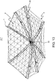
FIG. 13 is a perspective view of a deployable antenna according to a third embodiment of this invention. - Now, embodiments of this invention are described in detail.
-
FIG. 4 is an illustration of a deployable antenna A1' according to a first embodiment of this invention. The deployable antenna A1' alone may serve as a large deployable antenna corresponding to the large deployable antenna A0 illustrated inFIGS. 1 to 3 . - The deployable antenna A1' is stowed in a folded state inside a fairing of a launch vehicle, and is deployed in orbit to form an antenna reflector mirror surface (flexible reflector mirror surface 4), which is formed of a flexible film surface, into a predetermined parabolic shape.
- The deployable antenna A1' includes the flexible
reflector mirror surface 4, anantenna deploying mechanism 1 that supports an outer edge portion of the flexiblereflector mirror surface 4, andbands 3. The flexiblereflector mirror surface 4 serves as a front surface of the deployable antenna A1'. -
FIG. 5 is an illustration of theantenna deploying mechanism 1 of the deployable antenna A1' illustrated inFIG. 4 . - The
antenna deploying mechanism 1 includes sixdeployment link mechanisms 20 arranged radially from a central shaft of theantenna deploying mechanism 1 so as to support the outer edge portion of the flexiblereflector mirror surface 4 at six points, and onedeployment driving mechanism 30 arranged at a lower portion of the center of arrangement of the sixdeployment link mechanisms 20. Thedeployment driving mechanism 30 is an actuator mechanism part for unfolding the sixdeployment link mechanisms 20. - The
bands 3 illustrated inFIG. 4 are provided so as to adjust a phase angle of eachdeployment linkmechanism 20. -
FIG. 6 is an illustration of a singledeployment link mechanism 20 that is a component of the sixdeployment link mechanisms 20 of theantenna deploying mechanism 1 illustrated inFIG. 5 . - The single deployment linkmechanism20 includes three four-
side links deployment link mechanisms 20 are arranged, toward an outer side of thedeployment link mechanism 20. Thus, the deployment linkmechanism20 is structuredtobe foldable in three stages. InFIG. 6 , black spots represent hinge mechanisms. - Each deployable antenna module A1 of the deployable antenna A0 illustrated as the related art in
FIGS. 1 to 3 has an antenna deploying mechanism similar to theantenna deploying mechanism 1 illustrated inFIG. 5 . Specifically, the antenna deploying mechanism of the deployable antenna module A1 (FIGS. 1 to 3 ) also includes six radially arrangeddeployment link mechanisms 20 and onedeployment driving mechanism 30. However, thedeployment link mechanisms 20 of the deployable antenna module A1 (FIGS. 1 to 3 ) are each constructed of the four-side link 7 alone (single stage). - In contrast, according to the first embodiment, as illustrated in
FIG. 6 , thedeployment link mechanism 20 is constructed of the four-side links - In
FIG. 6 , a link member (central vertical link member) 8 of the four-side link 5, which serves as the central shaft, includes aslider 9. A link member (common vertical link member) 15 between the four-side links slider 16. Another link member (another common vertical link member) 8 between the four-side links slider 9. - In the single
deployment link mechanism 20 illustrated inFIG. 6 , the four-side link 6 is jointed to the four-side link 5 serving as a support structure for the deployable antenna A1', the four-side link 6 having a shape line-symmetric to that of the four-side link 5. Further, the four-side link 7 is jointed to the four-side link 6, the four-side link 7 having a shape line-symmetric to that of the four-side link 6. As described above, the three-fold structure is employed to increase an aperture diameter size of the single deployable antenna A1'. Specifically, the single deployable antenna A1' is structured to have an aperture diameter size that is substantially three times as large as the module aperture diameter size of the single deployable antenna module A1 (FIGS. 1 to 3 ). The deployable antenna A1' alone may serve as a large deployable antenna corresponding to the large deployable antenna A0 illustrated inFIGS. 1 to 3 . - In a case where the large deployable antenna A0 illustrated in
FIGS. 1 to 3 is constructed using the single deployable antenna A1' illustrated inFIG. 4 , only onedeployment driving mechanism 30 is necessary for the large deployable antenna A0, with the result that a lightweight, large deployable antenna is attained. -
FIG. 7 is an illustration of the four-side link 5 situated at the left end of thedeployment link mechanism 20 illustrated inFIG. 6 . - The four-
side link 5 is constructed of thelink member 8 andlink members side link 5, theslider 9, linkmembers slider 16, and alink member 17 are jointed through hinge mechanisms hg. - In
FIGS. 6 and7 , thedeployment driving mechanism 30 causes theslider 9 to slide upwardly along the centralvertical link member 8 serving as the central shaft. Accordingly, thelinkmember 10 brings the linkmembers 11 and 12 into an extended state, to thereby unfold the four-side link 5. The unfolded four-side link 5 causes theslider 16 to slide upwardly along the commonvertical link member 15, and accordingly the four-side link 6 is unfolded by thelink member 17. In this manner, the unfolded shape of the four-side link 6 is synchronized with the unfolded shape of the four-side link 5. As for the structure between the four-side link 6 and the four-side link 7, the unfolded four-side link 6 causes theslider 9 to slide upwardly along the another commonvertical link member 8. Accordingly, thelink member 10 brings thelink members side link 7. In this manner, the unfolded shape of the four-side link 7 is synchronized with the unfolded shape of the four-side link 6. -
FIG. 8 is an illustration of a right end portion of the four-side link 5 situated at the left end ofFIG. 6 and a left end portion of the four-side link 6 situated at the center ofFIG. 6 . Theslider 16 moves vertically along the commonvertical link member 15. One end of thelink member 17 is rotatably fixed to thelink member 14, and the other end of thelink member 17 is rotatably fixed to theslider 16. -
FIG. 9 is an illustration of a left end portion of the four-side link 5 situated at the left end ofFIGS. 6 and7 . -
FIG. 10 is an illustration of a right end portion of the four-side link 7 situated at the right end ofFIG. 6 . -
FIG. 11 is an illustration of thedeployment driving mechanism 30 ofFIG. 6 . Thedeployment driving mechanism 30 includes an actuator 31 (for example, a spring) for pushing theslider 9 up in the unfolding direction (that is, upwardly along the central vertical link member 8), and a damping device 32 (for example, a wire to be driven by a motor) for controlling the unfolding motion of theslider 9. Further, the four-side link may be folded when the dampingdevice 32 is moved in a reverse direction. - Now, an operation of the above-mentioned first embodiment is described.
- In
FIG. 7 , thedeployment driving mechanism 30 causes theslider 9 to slide upwardly along the centralvertical link member 8. Accordingly, thelinkmember 10 brings thelink members side link 5 constructed of thelink members - The
link members side link 5 in the unfolded state. - In
FIG. 7 , the unfolding force to be imparted by theslider 16 promotes the unfolding force to be imparted by theslider 9, and accordingly promotes the unfolding force of the entiredeployment link mechanism 20. - In
FIG. 6 , the four-side link 6 is line-symmetric to the four-side link 5, and hence unfolded line-symmetrically to the four-side link 5. Similarly, the four-side link 7 is unfolded line-symmetrically to the four-side link 6. Thus, thedeployment link mechanism 20 constructed of the four-side links sliders - In the first embodiment, the
deployment link mechanisms 20 foldable in three stages are used to provide a mechanism capable of folding and unfolding the deployable antenna A1' having a large aperture diameter. - The first embodiment enables the single deployable antenna A1' to serve as a large deployable antenna, to thereby reduce the weight of the large deployable antenna.
- Note that, in order to obtain a deployable antenna having such a large aperture diameter size that cannot be attained by the single deployable antenna A1' according to the first embodiment, similarly to the deployable antenna A0 of
FIGS. 1 to 3 , the outermost peripheral portions of a plurality of deployable antennas A1' (outermost peripheral portions of four-side links 7) only need to be jointed to one another by a plurality of joint members 40 (FIG. 3 ) to construct a jointed-type deployable antenna having a large aperture diameter size. -
FIG. 12 is an illustration of a deployment link mechanism 20' to be used in a deployable antenna according to a second embodiment of this invention. The deployment link mechanism 20' is constructed of five four-side links side links side links deployment link mechanism 20 ofFIG. 6 . The two added four-side links side links deployment link mechanism 20 ofFIG. 6 . - As described above, the five-fold structure is employed to increase the aperture diameter size of the deployable antenna. Specifically, the deployable antenna is structured to have an aperture diameter size that is substantially five times as large as the module aperture diameter size of the deployable antenna module A1 (
FIGS. 1 to 3 ). The deployable antenna alone may also serve as a large deployable antenna corresponding to the large deployable antenna A0 illustrated inFIGS. 1 to 3 . - Note that, in order to obtain a deployable antenna having such a large aperture diameter size that cannot be attained by the single deployable antenna according to the second embodiment, similarly to the deployable antenna A0 of
FIGS. 1 to 3 , the outermost peripheral portions of a plurality of deployable antennas (outermost peripheral portions of four-side links 7) only need to be jointed to one another by a plurality of joint members 40 (FIG. 3 ) to construct a jointed-type deployable antenna having a large aperture diameter size. - Now, referring to
FIGS. 4 to 7 and12 , various structures of the deployable antenna according to the first and second embodiments are summarized in the following items (1) to (7): - (1) A deployable antenna, including:
- six
deployment link mechanisms 20 arranged radially from a central shaft of the deployable antenna so as to support an outer edge portion of a flexiblereflector mirror surface 4 of the deployable antenna; and - one
deployment driving mechanism 30 arranged at a lower portion of a center of arrangement of the sixdeployment link mechanisms 20, for unfolding the sixdeployment link mechanisms 20, - in which each of the six
deployment link mechanisms 20 includes a first four-side link 5, a second four-side link 6, and a third four-side link 7 arranged in an order from a position of the central shaft, around which the sixdeployment link mechanisms 20 are arranged, toward an outer side of the each of the sixdeployment link mechanisms 20 so that the each of the sixdeployment link mechanisms 20 is structured to be foldable in three stages, - in which a central
vertical link member 8 of the first four-side link 5, which serves as the central shaft, includes afirst slider 9, - in which a common
vertical link member 15 between the first four-side link 5 and the second four-side link 6 includes asecond slider 16, - in which another common
vertical link member 8 between the second four-side link 6 and the third four-side link 7 includes athird slider 9, - in which the one
deployment driving mechanism 30 causes thefirst slider 9 to slide upwardly along the centralvertical link member 8, to thereby unfold the first four-side link 5, - in which the unfolded first four-
side link 5 causes thesecond slider 16 to slide upwardly along the commonvertical link member 15, to thereby unfold the second four-side link 6, and - in which the unfolded second four-
side link 6 causes thethird slider 9 to slide upwardly along the another commonvertical link member 8, to thereby unfold the third four-side link 7.
- six
- (2) A deployable antenna according to the above-mentioned item (1), in which the first four-
side link 5 includeslink mechanisms deployment driving mechanism 30 causes thefirst slider 9 to slide upwardly along the centralvertical link member 8, to thereby unfold the first four-side link 5. - (3) A deployable antenna according to the above-mentioned item (1) or (2),
in which the first four-side link 5 further includes a first promotinglink member 17 for promoting unfolding of the first four-side link 5 when the unfolded first four-side link 5 causes thesecond slider 16 to slide upwardly along the commonvertical link member 15, and
in which the second four-side link 6 includes a second promotinglink member 17 for promoting unfolding of the second four-side link 6 when the unfolded first four-side link 5 causes thesecond slider 16 to slide upwardly along the commonvertical link member 15. - (4) A deployable antenna according to any one of the above-mentioned items (1) to (3), in which the third four-
side link 7 includeslink mechanisms side link 6 causes thethird slider 9 to slide upwardly along the another commonvertical link member 8, to thereby unfold the third four-side link 7. - (5) A jointed-type deployable antenna, including:
- a plurality of the deployable antennas A1' according to any one of the above-mentioned items (1) to (4); and
- a plurality of joint members 40 (
FIG. 3 ) for jointing outermost peripheral portions of the plurality of the deployable antennas to one another.
- (6) A deployable antenna according to the above-mentioned item (1),
in which the each of the six deployment link mechanisms 20' further includes a fourth four-side link 5 and a fifth four-side link 6 arranged between the second four-side link 6 and the third four-side link 7 so that the each of the six deployment link mechanisms 20' is structured to be foldable in five stages, and
in which the fourth four-side link 5 and the fifth four-side link 6 have substantially the same structures as the first four-side link 5 and the second four-side link 6. - (7) A jointed-type deployable antenna, including:
- apluralityof the deployable antennas according to the above-mentioned item (6); and
- a plurality of joint members 40 (
FIG. 3 ) for jointing outermost peripheral portions of the plurality of the deployable antennas to one another. -
FIG. 13 is an illustration of a deployable antenna A1" according to a third embodiment of this invention. The deployable antenna A1" is an octagonal deployable antenna obtained by radially providing thedeployment link mechanisms 20 at eight points so as to support the outer peripheral edge portion of the flexiblereflector mirror surface 4 at eight points. The octagonal deployable antenna A1" has such an elliptical aperture shape that an axial projection shape of the parabola of the flexiblereflector mirror surface 4 is formed into a circular aperture. Each of thedeployment link mechanisms 20 provided at eight points has a similar structure as that ofFIGS. 6 and7 . - Note that, in the deployable antenna A1" illustrated in
FIG. 13 , the deployment link mechanism 20' illustrated inFIG. 12 may be used as each of the eightdeployment link mechanisms 20. As described above, the deployment link mechanism 20' is constructed of five four-side links side links side links deployment link mechanism 20 ofFIG. 6 . The two added four-side links side links deployment link mechanism 20 ofFIG. 6 . - Now, referring to
FIGS. 13 ,6 ,7 , and12 , various structures of the deployable antenna A1" according to the third embodiment are summarized in the following items (8) and (9):
- (8) A deployable antenna A1", including:
- eight
deployment link mechanisms 20 arranged radially from a central shaft of the deployable antenna so as to support an outer edge portion of a flexiblereflector mirror surface 4 of the deployable antenna; and - one
deployment driving mechanism 30 arranged at a lower portion of a center of arrangement of the eightdeployment link mechanisms 20, for unfolding the eightdeployment link mechanisms 20, - in which each of the eight
deployment link mechanisms 20 includes a first four-side link 5, a second four-side link 6, and a third four-side link 7 arranged in an order from a position of the central shaft, around which the eightdeployment link mechanisms 20 are arranged, toward an outer side of the each of the eightdeployment link mechanisms 20 so that the each of the eightdeployment link mechanisms 20 is structured to be foldable in three stages, - in which a central
vertical link member 8 of the first four-side link 5, which serves as the central shaft, includes afirst slider 9, - in which a common
vertical link member 15 between the first four-side link 5 and the second four-side link 6 includes asecond slider 16, - in which another common
vertical link member 8 between the second four-side link 6 and the third four-side link 7 includes athird slider 9, - in which the one
deployment driving mechanism 30 causes thefirst slider 9 to slide upwardly along the centralvertical link member 8, to thereby unfold the first four-side link 5, - in which the unfolded first four-
side link 5 causes thesecond slider 16 to slide upwardly along the commonvertical link member 15, to thereby unfold the second four-side link 6, and - in which the unfolded second four-
side link 6 causes thethird slider 9 to slide upwardly along the another commonvertical link member 8, to thereby unfold the third four-side link 7.
- eight
- (9) A deployable antenna according to the above-mentioned item (8),
in which the each of the eightdeployment link mechanisms 20 further includes a fourth four-side link 5 and a fifth four-side link 6 arranged between the second four-side link 6 and the third four-side link 7 so that the each of the eightdeployment link mechanisms 20 is structured to be foldable in five stages, and
in which the fourth four-side link 5 and the fifth four-side link 6 have substantially the same structures as the first four-side link 5 and the second four-side link 6. - This invention is applicable to a folding mechanism of a deployable antenna, of the parabolic antennas to be mounted onto an artificial satellite or the like.
- This invention has been described above in detail with reference to the embodiments, but this invention is not limited to the embodiments described above. Various modifications understandable for a person having ordinary skill in the art may be made to the structures and details of this invention within the scope of this invention.
Claims (9)
- A deployable antenna, comprising:six deployment link mechanisms (20) arranged radially from a central shaft of the deployable antenna so as to support an outer edge portion of a flexible reflector mirror surface of the deployable antenna; andone deployment driving mechanism (30) arranged at a lower portion of a center of arrangement of the six deployment link mechanisms, for unfolding the six deployment link mechanisms,wherein each of the six deployment link mechanisms comprises a first four-side link (5), a second four-side link (6), and a third four-side link (7) arranged in an order from a position of the central shaft, around which the six deployment linkmechanisms are arranged, toward an outer side of the each of the six deployment linkmechanisms so that the each of the six deployment link mechanisms is structured to be foldable in three stages,wherein a central vertical link member (8) of the first four-side link (5), which serves as the central shaft, comprises a first slider (9),wherein a common vertical link member (15) between the first four-side link (5) and the second four-side link (6)comprises a second slider (16),wherein another common vertical link member (8) between the second four-side link (6) and the third four-side link (7) comprises a third slider,wherein the one deployment driving mechanism (30) causes the first slider (9) to slide upwardly along the central vertical link member (8), to thereby unfold the first four-side link (5),wherein the unfolded first four-side link (5) causes the second slider (6) to slide upwardly along the common vertical linkmember (15), to there by unfold the second four-side link, andwherein the unfolded second four-side link (6) causes the third slider (9) to slide upwardly along the another common vertical link member (8), to thereby unfold the third four-side link (7).
- A deployable antenna according to claim 1, wherein the first four-side link (5) comprises a link mechanism (10, 11, 12) to be brought into an extended state when the one deployment driving mechanism (30) causes the first slider (9) to slide upwardly along the central vertical link member (8), to thereby unfold the first four-side link (5).
- A deployable antenna according to claim 1 or 2,
wherein the first four-side link (5) further comprises a first promoting link member (17) for promoting unfolding of the first four-side link (5) when the unfolded first four-side link (5) causes the second slider (16) to slide upwardly along the common vertical link member, and
wherein the second four-side link (6) comprises a second promoting link member for promoting unfolding of the second four-side link when the unfolded first four-side link causes the second slider to slide upwardly along the common vertical link member (15). - A deployable antenna according to any one of claims 1 to 3, wherein the third four-side link (7) comprises a link mechanism (10, 11, 12) to be brought into an extended state when the unfolded second four-side link (6) causes the third slider (9) to slide upwardly along the another common vertical link member (8), to thereby unfold the third four-side link.
- A jointed-type deployable antenna, comprising:a plurality of the deployable antennas (A1') according to any one of claims 1 to 4; anda plurality of joint members (40) for jointing outermost peripheral portions of the plurality of the deployable antennas to one another.
- A deployable antenna according to claim 1,
wherein the each of the six deployment link mechanisms further comprises a fourth four-side link (5) and a fifth four-side link (6) arranged between the second four-side link (6) and the third four-side link (7) so that the each of the six deployment link mechanisms is structured to be foldable in five stages, and
wherein the fourth four-side link (5) and the fifth four-side link have substantially the same structures as the first four-side link and the second four-side link. - A jointed-type deployable antenna, comprising:apluralityof the deployable antennas according to claim 6; anda plurality of joint members (40) for jointing outermost peripheral portions of the plurality of the deployable antennas to one another.
- A deployable antenna, comprising:eight deployment link mechanisms (20) arranged radially from a central shaft of the deployable antenna so as to support an outer edge portion of a flexible reflector mirror surface (4) of the deployable antenna; andone deployment driving mechanism (30) arranged at a lower portion of a center of arrangement of the eight deployment link mechanisms (20), for unfolding the eight deployment link mechanisms (20),wherein each of the eight deployment link mechanisms comprises a first four-side link (5), a second four-side link (6), and a third four-side link (7) arranged in an order from a position of the central shaft, around which the eight deployment linkmechanisms (20) are arranged, toward an outer side of the each of the eight deployment link mechanisms so that the each of the eight deployment link mechanisms is structured to be foldable in three stages,wherein a central vertical link member (8) of the first four-side link (5), which serves as the central shaft, comprises a first slider (9),wherein a common vertical link member (15) between the first four-side link (5) and the second four-side link (6) comprises a second slider (16),wherein another common vertical link member (8) between the second four-side link (5) and the third four-side link (7) comprises a third slider (9),wherein the one deployment driving mechanism (30) causes the first slider (9) to slide upwardly along the central vertical link member (8), to thereby unfold the first four-side link,wherein the unfolded first four-side link (5) causes the second slider (16) to slide upwardly along the common vertical linkmember (15), to thereby unfold the second four-side link, andwherein the unfolded second four-side link (6) causes the third slider (9) to slide upwardly along the another common vertical link member (8), to thereby unfold the third four-side link (7).
- A deployable antenna according to claim 8,
wherein the each of the eight deployment link mechanisms (20) further comprises a fourth four-side link (5) and a fifth four-side link (6) arrangedbetween the second four-side link (6) and the third four-side link (7) so that the each of the eight deployment link mechanisms (20) is structured to be foldable in five stages, and
wherein the fourth four-side link (5) and the fifth four-side link (6) have substantially the same structures as the first four-side link (5) and the second four-side link (6).
Applications Claiming Priority (1)
| Application Number | Priority Date | Filing Date | Title |
|---|---|---|---|
| JP2011017529A JP5732656B2 (en) | 2011-01-31 | 2011-01-31 | Deployable antenna |
Publications (2)
| Publication Number | Publication Date |
|---|---|
| EP2482378A1 true EP2482378A1 (en) | 2012-08-01 |
| EP2482378B1 EP2482378B1 (en) | 2017-11-15 |
Family
ID=45524444
Family Applications (1)
| Application Number | Title | Priority Date | Filing Date |
|---|---|---|---|
| EP12152827.7A Not-in-force EP2482378B1 (en) | 2011-01-31 | 2012-01-27 | Deployable antenna |
Country Status (4)
| Country | Link |
|---|---|
| US (1) | US8922456B2 (en) |
| EP (1) | EP2482378B1 (en) |
| JP (1) | JP5732656B2 (en) |
| CN (1) | CN102623787B (en) |
Cited By (5)
| Publication number | Priority date | Publication date | Assignee | Title |
|---|---|---|---|---|
| WO2021000137A1 (en) * | 2019-06-30 | 2021-01-07 | 瑞声声学科技(深圳)有限公司 | Antenna oscillator |
| WO2021058838A1 (en) | 2019-09-24 | 2021-04-01 | Airbus Defence And Space, S.A. | Deployable assembly for antennas |
| US11608632B2 (en) | 2019-01-28 | 2023-03-21 | William E. Smith | Pre-stressed sinusoidal member in assembly and applications |
| US11959277B1 (en) | 2019-01-28 | 2024-04-16 | William E. Smith | Pre-stressed sinusoidal member in assembly and applications |
| EP4593196A1 (en) | 2024-01-25 | 2025-07-30 | Airbus Defence and Space S.A. | Deployable reflector |
Families Citing this family (13)
| Publication number | Priority date | Publication date | Assignee | Title |
|---|---|---|---|---|
| EP2643882B1 (en) | 2010-12-15 | 2014-04-16 | Skybox Imaging, Inc. | Integrated antenna system for imaging microsatellites |
| CN102832438B (en) * | 2012-08-28 | 2014-07-16 | 西北工业大学 | Regular-triangle-unit planar array deployable mechanism |
| PL2915213T3 (en) * | 2012-11-05 | 2017-02-28 | Thales Alenia Space Italia S.P.A. Con Unico Socio | Large deployable reflector for a satellite antenna |
| CN103825098A (en) * | 2014-02-18 | 2014-05-28 | 哈尔滨工业大学深圳研究生院 | Framework type spatial foldable antenna unfolding mechanism |
| CN106450649B (en) * | 2016-12-07 | 2019-02-01 | 上海宇航系统工程研究所 | A kind of H configuration satellite antenna development agency |
| CN106864772B (en) * | 2017-01-24 | 2021-06-01 | 航天东方红卫星有限公司 | Spacecraft prestressed thin-walled conical multi-rod parallel parallel space deployment mechanism |
| GB201701568D0 (en) * | 2017-01-31 | 2017-03-15 | Oxford Space Systems Ltd | Actuating support member |
| KR101989113B1 (en) * | 2017-09-19 | 2019-07-02 | (주)사이버텔브릿지 | Terminal including pen-shaped external directional antenna and operation method of the terminal |
| WO2020036623A2 (en) * | 2018-01-08 | 2020-02-20 | Umbra Lab, Inc. | Articulated folding rib reflector for concentrating radiation |
| CN109935951B (en) * | 2019-04-12 | 2021-04-02 | 福建星海通信科技有限公司 | Antenna capable of being unfolded and folded |
| CN111129695B (en) * | 2019-12-10 | 2021-01-08 | 西安电子科技大学 | Frame-type deployment antenna center pole device based on movable joint |
| CN112259949B (en) * | 2020-09-16 | 2023-08-29 | 航天东方红卫星有限公司 | High storage ratio modular folding support truss |
| CN113241513B (en) * | 2021-05-11 | 2022-07-26 | 北京航空航天大学 | Folding and unfolding assembly and antenna supporting mechanism with same |
Citations (8)
| Publication number | Priority date | Publication date | Assignee | Title |
|---|---|---|---|---|
| DE2941170A1 (en) * | 1979-10-11 | 1981-06-19 | Messerschmitt-Bölkow-Blohm GmbH, 8000 München | Expanding dish aerial for orbiting transmitters - consists of interlinked pantograph elements which when closed give compact unit for transport |
| EP0290729A2 (en) * | 1987-05-14 | 1988-11-17 | Mitsubishi Denki Kabushiki Kaisha | Module for expandable truss structure and expandable truss structure employing said module |
| JPH11112228A (en) | 1997-09-29 | 1999-04-23 | Nippon Telegr & Teleph Corp <Ntt> | Deployable antenna |
| JP2000183640A (en) * | 1998-12-10 | 2000-06-30 | Japan Science & Technology Corp | Deployable frame structure |
| JP2003095199A (en) | 2001-09-19 | 2003-04-03 | Nec Toshiba Space System Kk | Deployable antenna |
| WO2005027186A2 (en) | 2003-09-10 | 2005-03-24 | Nippon Telegraph & Telephone | Expansion-type reflection mirror |
| JP2006080577A (en) | 2003-09-10 | 2006-03-23 | Nippon Telegr & Teleph Corp <Ntt> | Deployment antenna |
| JP2011017529A (en) | 2010-08-25 | 2011-01-27 | Tokyo Yogyo Co Ltd | Lance pipe |
Family Cites Families (15)
| Publication number | Priority date | Publication date | Assignee | Title |
|---|---|---|---|---|
| US4845511A (en) * | 1987-01-27 | 1989-07-04 | Harris Corp. | Space deployable domed solar concentrator with foldable panels and hinge therefor |
| JPH02241208A (en) * | 1989-03-15 | 1990-09-25 | Mitsubishi Electric Corp | Expansion truss antenna |
| JPH06156396A (en) * | 1992-11-25 | 1994-06-03 | Mitsubishi Electric Corp | Truss deployment structure |
| FR2746365B1 (en) * | 1996-03-20 | 1998-06-12 | Centre Nat Etd Spatiales | IMPROVEMENTS TO OBSERVATION OR TELECOMMUNICATION SATELLITES |
| US6219009B1 (en) * | 1997-06-30 | 2001-04-17 | Harris Corporation | Tensioned cord/tie attachment of antenna reflector to inflatable radial truss support structure |
| JP4247755B2 (en) * | 1998-02-24 | 2009-04-02 | 独立行政法人 宇宙航空研究開発機構 | Expanded truss structure and antenna reflector |
| JPH11247290A (en) * | 1998-02-27 | 1999-09-14 | Mitsubishi Electric Corp | Deployable frame structure |
| US6618025B2 (en) * | 1999-06-11 | 2003-09-09 | Harris Corporation | Lightweight, compactly deployable support structure with telescoping members |
| US6826225B1 (en) * | 1999-07-23 | 2004-11-30 | Silicon Laboratories, Inc. | Integrated modem and line-isolation circuitry with selective raw data or modem data communication and associated method |
| JP4273281B2 (en) * | 2000-02-25 | 2009-06-03 | 独立行政法人 宇宙航空研究開発機構 | Space expansion structure |
| US6836215B1 (en) * | 2002-01-22 | 2004-12-28 | The Standard Register Company | Printable identification band with top strip for RFID chip attachment |
| US6828949B2 (en) * | 2002-04-29 | 2004-12-07 | Harris Corporation | Solid surface implementation for deployable reflectors |
| JP2004146898A (en) * | 2002-10-22 | 2004-05-20 | Nec Toshiba Space Systems Ltd | Deployable mesh antenna |
| US7595769B2 (en) * | 2006-02-28 | 2009-09-29 | The Boeing Company | Arbitrarily shaped deployable mesh reflectors |
| US20130107889A1 (en) * | 2011-11-02 | 2013-05-02 | International Business Machines Corporation | Distributed Address Resolution Service for Virtualized Networks |
-
2011
- 2011-01-31 JP JP2011017529A patent/JP5732656B2/en not_active Expired - Fee Related
-
2012
- 2012-01-27 EP EP12152827.7A patent/EP2482378B1/en not_active Not-in-force
- 2012-01-29 CN CN201210021574.8A patent/CN102623787B/en not_active Expired - Fee Related
- 2012-01-30 US US13/361,234 patent/US8922456B2/en not_active Expired - Fee Related
Patent Citations (9)
| Publication number | Priority date | Publication date | Assignee | Title |
|---|---|---|---|---|
| DE2941170A1 (en) * | 1979-10-11 | 1981-06-19 | Messerschmitt-Bölkow-Blohm GmbH, 8000 München | Expanding dish aerial for orbiting transmitters - consists of interlinked pantograph elements which when closed give compact unit for transport |
| EP0290729A2 (en) * | 1987-05-14 | 1988-11-17 | Mitsubishi Denki Kabushiki Kaisha | Module for expandable truss structure and expandable truss structure employing said module |
| JPH11112228A (en) | 1997-09-29 | 1999-04-23 | Nippon Telegr & Teleph Corp <Ntt> | Deployable antenna |
| JP2000183640A (en) * | 1998-12-10 | 2000-06-30 | Japan Science & Technology Corp | Deployable frame structure |
| JP2003095199A (en) | 2001-09-19 | 2003-04-03 | Nec Toshiba Space System Kk | Deployable antenna |
| WO2005027186A2 (en) | 2003-09-10 | 2005-03-24 | Nippon Telegraph & Telephone | Expansion-type reflection mirror |
| JP2006080577A (en) | 2003-09-10 | 2006-03-23 | Nippon Telegr & Teleph Corp <Ntt> | Deployment antenna |
| US20060181788A1 (en) * | 2003-09-10 | 2006-08-17 | Nippon Telegraph And Telephone Corporation | Expansion-type reflection mirror |
| JP2011017529A (en) | 2010-08-25 | 2011-01-27 | Tokyo Yogyo Co Ltd | Lance pipe |
Cited By (6)
| Publication number | Priority date | Publication date | Assignee | Title |
|---|---|---|---|---|
| US11608632B2 (en) | 2019-01-28 | 2023-03-21 | William E. Smith | Pre-stressed sinusoidal member in assembly and applications |
| US11959277B1 (en) | 2019-01-28 | 2024-04-16 | William E. Smith | Pre-stressed sinusoidal member in assembly and applications |
| WO2021000137A1 (en) * | 2019-06-30 | 2021-01-07 | 瑞声声学科技(深圳)有限公司 | Antenna oscillator |
| WO2021058838A1 (en) | 2019-09-24 | 2021-04-01 | Airbus Defence And Space, S.A. | Deployable assembly for antennas |
| US11784415B2 (en) | 2019-09-24 | 2023-10-10 | Airbus Defence and Space S.A. | Deployable assembly for antennas |
| EP4593196A1 (en) | 2024-01-25 | 2025-07-30 | Airbus Defence and Space S.A. | Deployable reflector |
Also Published As
| Publication number | Publication date |
|---|---|
| US8922456B2 (en) | 2014-12-30 |
| CN102623787B (en) | 2016-02-17 |
| JP5732656B2 (en) | 2015-06-10 |
| CN102623787A (en) | 2012-08-01 |
| US20120193498A1 (en) | 2012-08-02 |
| JP2012160809A (en) | 2012-08-23 |
| EP2482378B1 (en) | 2017-11-15 |
Similar Documents
| Publication | Publication Date | Title |
|---|---|---|
| US8922456B2 (en) | Deployable antenna | |
| US9608333B1 (en) | Scalable high compaction ratio mesh hoop column deployable reflector system | |
| EP3614487B1 (en) | Folded rip truss structure for reflector antenna with zero over stretch | |
| EP3598576B1 (en) | Reflecting systems, such as reflector antenna systems, with tension-stabilized reflector positional apparatus | |
| JP7459237B2 (en) | Deployable assembly for antenna | |
| JP4876941B2 (en) | Deployable antenna | |
| WO2002025767A1 (en) | Deployment of an electronically scanned reflector | |
| EP3923412B1 (en) | Systems and methods for providing antennas with mechanically coupled offset posititons | |
| EP3709436B1 (en) | High compaction ratio reflector antenna with offset optics | |
| US11319093B2 (en) | Deployment mechanism for reflector antenna system | |
| US7180470B1 (en) | Enhanced antenna stowage and deployment system | |
| JP2642591B2 (en) | Deployable antenna reflector | |
| RU2795105C1 (en) | Deployable antenna assembly | |
| JP3133056B2 (en) | Synchronous drive mechanism for deployable antenna and ring | |
| KR20260012412A (en) | Self-locking hinge device with oblique rotation axis for deployable wrapped rib antenna and manufacturing method thereof | |
| JPS6249706A (en) | Expansion type antenna reflector | |
| JP3848057B2 (en) | Deployable antenna reflector structure | |
| JP2000096715A (en) | Deployable truss structure |
Legal Events
| Date | Code | Title | Description |
|---|---|---|---|
| PUAI | Public reference made under article 153(3) epc to a published international application that has entered the european phase |
Free format text: ORIGINAL CODE: 0009012 |
|
| AK | Designated contracting states |
Kind code of ref document: A1 Designated state(s): AL AT BE BG CH CY CZ DE DK EE ES FI FR GB GR HR HU IE IS IT LI LT LU LV MC MK MT NL NO PL PT RO RS SE SI SK SM TR |
|
| AX | Request for extension of the european patent |
Extension state: BA ME |
|
| 17P | Request for examination filed |
Effective date: 20130115 |
|
| 17Q | First examination report despatched |
Effective date: 20150505 |
|
| RAP1 | Party data changed (applicant data changed or rights of an application transferred) |
Owner name: NEC SPACE TECHNOLOGIES, LTD. Owner name: JAPAN AEROSPACE EXPLORATION AGENCY |
|
| STAA | Information on the status of an ep patent application or granted ep patent |
Free format text: STATUS: EXAMINATION IS IN PROGRESS |
|
| GRAP | Despatch of communication of intention to grant a patent |
Free format text: ORIGINAL CODE: EPIDOSNIGR1 |
|
| STAA | Information on the status of an ep patent application or granted ep patent |
Free format text: STATUS: GRANT OF PATENT IS INTENDED |
|
| INTG | Intention to grant announced |
Effective date: 20170608 |
|
| GRAS | Grant fee paid |
Free format text: ORIGINAL CODE: EPIDOSNIGR3 |
|
| GRAA | (expected) grant |
Free format text: ORIGINAL CODE: 0009210 |
|
| STAA | Information on the status of an ep patent application or granted ep patent |
Free format text: STATUS: THE PATENT HAS BEEN GRANTED |
|
| AK | Designated contracting states |
Kind code of ref document: B1 Designated state(s): AL AT BE BG CH CY CZ DE DK EE ES FI FR GB GR HR HU IE IS IT LI LT LU LV MC MK MT NL NO PL PT RO RS SE SI SK SM TR |
|
| REG | Reference to a national code |
Ref country code: CH Ref legal event code: EP Ref country code: GB Ref legal event code: FG4D Ref country code: AT Ref legal event code: REF Ref document number: 947126 Country of ref document: AT Kind code of ref document: T Effective date: 20171115 |
|
| REG | Reference to a national code |
Ref country code: FR Ref legal event code: PLFP Year of fee payment: 7 |
|
| REG | Reference to a national code |
Ref country code: IE Ref legal event code: FG4D |
|
| REG | Reference to a national code |
Ref country code: DE Ref legal event code: R096 Ref document number: 602012039679 Country of ref document: DE |
|
| REG | Reference to a national code |
Ref country code: NL Ref legal event code: MP Effective date: 20171115 |
|
| REG | Reference to a national code |
Ref country code: LT Ref legal event code: MG4D |
|
| REG | Reference to a national code |
Ref country code: AT Ref legal event code: MK05 Ref document number: 947126 Country of ref document: AT Kind code of ref document: T Effective date: 20171115 |
|
| PG25 | Lapsed in a contracting state [announced via postgrant information from national office to epo] |
Ref country code: NO Free format text: LAPSE BECAUSE OF FAILURE TO SUBMIT A TRANSLATION OF THE DESCRIPTION OR TO PAY THE FEE WITHIN THE PRESCRIBED TIME-LIMIT Effective date: 20180215 Ref country code: FI Free format text: LAPSE BECAUSE OF FAILURE TO SUBMIT A TRANSLATION OF THE DESCRIPTION OR TO PAY THE FEE WITHIN THE PRESCRIBED TIME-LIMIT Effective date: 20171115 Ref country code: SE Free format text: LAPSE BECAUSE OF FAILURE TO SUBMIT A TRANSLATION OF THE DESCRIPTION OR TO PAY THE FEE WITHIN THE PRESCRIBED TIME-LIMIT Effective date: 20171115 Ref country code: NL Free format text: LAPSE BECAUSE OF FAILURE TO SUBMIT A TRANSLATION OF THE DESCRIPTION OR TO PAY THE FEE WITHIN THE PRESCRIBED TIME-LIMIT Effective date: 20171115 Ref country code: LT Free format text: LAPSE BECAUSE OF FAILURE TO SUBMIT A TRANSLATION OF THE DESCRIPTION OR TO PAY THE FEE WITHIN THE PRESCRIBED TIME-LIMIT Effective date: 20171115 Ref country code: ES Free format text: LAPSE BECAUSE OF FAILURE TO SUBMIT A TRANSLATION OF THE DESCRIPTION OR TO PAY THE FEE WITHIN THE PRESCRIBED TIME-LIMIT Effective date: 20171115 |
|
| PG25 | Lapsed in a contracting state [announced via postgrant information from national office to epo] |
Ref country code: GR Free format text: LAPSE BECAUSE OF FAILURE TO SUBMIT A TRANSLATION OF THE DESCRIPTION OR TO PAY THE FEE WITHIN THE PRESCRIBED TIME-LIMIT Effective date: 20180216 Ref country code: HR Free format text: LAPSE BECAUSE OF FAILURE TO SUBMIT A TRANSLATION OF THE DESCRIPTION OR TO PAY THE FEE WITHIN THE PRESCRIBED TIME-LIMIT Effective date: 20171115 Ref country code: BG Free format text: LAPSE BECAUSE OF FAILURE TO SUBMIT A TRANSLATION OF THE DESCRIPTION OR TO PAY THE FEE WITHIN THE PRESCRIBED TIME-LIMIT Effective date: 20180215 Ref country code: LV Free format text: LAPSE BECAUSE OF FAILURE TO SUBMIT A TRANSLATION OF THE DESCRIPTION OR TO PAY THE FEE WITHIN THE PRESCRIBED TIME-LIMIT Effective date: 20171115 Ref country code: AT Free format text: LAPSE BECAUSE OF FAILURE TO SUBMIT A TRANSLATION OF THE DESCRIPTION OR TO PAY THE FEE WITHIN THE PRESCRIBED TIME-LIMIT Effective date: 20171115 Ref country code: RS Free format text: LAPSE BECAUSE OF FAILURE TO SUBMIT A TRANSLATION OF THE DESCRIPTION OR TO PAY THE FEE WITHIN THE PRESCRIBED TIME-LIMIT Effective date: 20171115 |
|
| PG25 | Lapsed in a contracting state [announced via postgrant information from national office to epo] |
Ref country code: DK Free format text: LAPSE BECAUSE OF FAILURE TO SUBMIT A TRANSLATION OF THE DESCRIPTION OR TO PAY THE FEE WITHIN THE PRESCRIBED TIME-LIMIT Effective date: 20171115 Ref country code: EE Free format text: LAPSE BECAUSE OF FAILURE TO SUBMIT A TRANSLATION OF THE DESCRIPTION OR TO PAY THE FEE WITHIN THE PRESCRIBED TIME-LIMIT Effective date: 20171115 Ref country code: CY Free format text: LAPSE BECAUSE OF FAILURE TO SUBMIT A TRANSLATION OF THE DESCRIPTION OR TO PAY THE FEE WITHIN THE PRESCRIBED TIME-LIMIT Effective date: 20171115 Ref country code: CZ Free format text: LAPSE BECAUSE OF FAILURE TO SUBMIT A TRANSLATION OF THE DESCRIPTION OR TO PAY THE FEE WITHIN THE PRESCRIBED TIME-LIMIT Effective date: 20171115 Ref country code: SK Free format text: LAPSE BECAUSE OF FAILURE TO SUBMIT A TRANSLATION OF THE DESCRIPTION OR TO PAY THE FEE WITHIN THE PRESCRIBED TIME-LIMIT Effective date: 20171115 |
|
| REG | Reference to a national code |
Ref country code: DE Ref legal event code: R119 Ref document number: 602012039679 Country of ref document: DE |
|
| PG25 | Lapsed in a contracting state [announced via postgrant information from national office to epo] |
Ref country code: PL Free format text: LAPSE BECAUSE OF FAILURE TO SUBMIT A TRANSLATION OF THE DESCRIPTION OR TO PAY THE FEE WITHIN THE PRESCRIBED TIME-LIMIT Effective date: 20171115 Ref country code: RO Free format text: LAPSE BECAUSE OF FAILURE TO SUBMIT A TRANSLATION OF THE DESCRIPTION OR TO PAY THE FEE WITHIN THE PRESCRIBED TIME-LIMIT Effective date: 20171115 Ref country code: SM Free format text: LAPSE BECAUSE OF FAILURE TO SUBMIT A TRANSLATION OF THE DESCRIPTION OR TO PAY THE FEE WITHIN THE PRESCRIBED TIME-LIMIT Effective date: 20171115 |
|
| REG | Reference to a national code |
Ref country code: CH Ref legal event code: PL |
|
| PLBE | No opposition filed within time limit |
Free format text: ORIGINAL CODE: 0009261 |
|
| STAA | Information on the status of an ep patent application or granted ep patent |
Free format text: STATUS: NO OPPOSITION FILED WITHIN TIME LIMIT |
|
| 26N | No opposition filed |
Effective date: 20180817 |
|
| GBPC | Gb: european patent ceased through non-payment of renewal fee |
Effective date: 20180215 |
|
| PG25 | Lapsed in a contracting state [announced via postgrant information from national office to epo] |
Ref country code: LU Free format text: LAPSE BECAUSE OF NON-PAYMENT OF DUE FEES Effective date: 20180127 Ref country code: DE Free format text: LAPSE BECAUSE OF NON-PAYMENT OF DUE FEES Effective date: 20180801 |
|
| REG | Reference to a national code |
Ref country code: IE Ref legal event code: MM4A |
|
| REG | Reference to a national code |
Ref country code: BE Ref legal event code: MM Effective date: 20180131 |
|
| PG25 | Lapsed in a contracting state [announced via postgrant information from national office to epo] |
Ref country code: SI Free format text: LAPSE BECAUSE OF FAILURE TO SUBMIT A TRANSLATION OF THE DESCRIPTION OR TO PAY THE FEE WITHIN THE PRESCRIBED TIME-LIMIT Effective date: 20171115 Ref country code: BE Free format text: LAPSE BECAUSE OF NON-PAYMENT OF DUE FEES Effective date: 20180131 Ref country code: CH Free format text: LAPSE BECAUSE OF NON-PAYMENT OF DUE FEES Effective date: 20180131 Ref country code: LI Free format text: LAPSE BECAUSE OF NON-PAYMENT OF DUE FEES Effective date: 20180131 |
|
| PG25 | Lapsed in a contracting state [announced via postgrant information from national office to epo] |
Ref country code: IE Free format text: LAPSE BECAUSE OF NON-PAYMENT OF DUE FEES Effective date: 20180127 |
|
| PG25 | Lapsed in a contracting state [announced via postgrant information from national office to epo] |
Ref country code: GB Free format text: LAPSE BECAUSE OF NON-PAYMENT OF DUE FEES Effective date: 20180215 |
|
| PG25 | Lapsed in a contracting state [announced via postgrant information from national office to epo] |
Ref country code: MC Free format text: LAPSE BECAUSE OF FAILURE TO SUBMIT A TRANSLATION OF THE DESCRIPTION OR TO PAY THE FEE WITHIN THE PRESCRIBED TIME-LIMIT Effective date: 20171115 |
|
| PG25 | Lapsed in a contracting state [announced via postgrant information from national office to epo] |
Ref country code: MT Free format text: LAPSE BECAUSE OF NON-PAYMENT OF DUE FEES Effective date: 20180127 |
|
| PGFP | Annual fee paid to national office [announced via postgrant information from national office to epo] |
Ref country code: FR Payment date: 20191216 Year of fee payment: 9 |
|
| PG25 | Lapsed in a contracting state [announced via postgrant information from national office to epo] |
Ref country code: TR Free format text: LAPSE BECAUSE OF FAILURE TO SUBMIT A TRANSLATION OF THE DESCRIPTION OR TO PAY THE FEE WITHIN THE PRESCRIBED TIME-LIMIT Effective date: 20171115 |
|
| PGFP | Annual fee paid to national office [announced via postgrant information from national office to epo] |
Ref country code: IT Payment date: 20200114 Year of fee payment: 9 |
|
| PG25 | Lapsed in a contracting state [announced via postgrant information from national office to epo] |
Ref country code: HU Free format text: LAPSE BECAUSE OF FAILURE TO SUBMIT A TRANSLATION OF THE DESCRIPTION OR TO PAY THE FEE WITHIN THE PRESCRIBED TIME-LIMIT; INVALID AB INITIO Effective date: 20120127 Ref country code: PT Free format text: LAPSE BECAUSE OF FAILURE TO SUBMIT A TRANSLATION OF THE DESCRIPTION OR TO PAY THE FEE WITHIN THE PRESCRIBED TIME-LIMIT Effective date: 20171115 |
|
| PG25 | Lapsed in a contracting state [announced via postgrant information from national office to epo] |
Ref country code: MK Free format text: LAPSE BECAUSE OF NON-PAYMENT OF DUE FEES Effective date: 20171115 |
|
| PG25 | Lapsed in a contracting state [announced via postgrant information from national office to epo] |
Ref country code: AL Free format text: LAPSE BECAUSE OF FAILURE TO SUBMIT A TRANSLATION OF THE DESCRIPTION OR TO PAY THE FEE WITHIN THE PRESCRIBED TIME-LIMIT Effective date: 20171115 Ref country code: IS Free format text: LAPSE BECAUSE OF FAILURE TO SUBMIT A TRANSLATION OF THE DESCRIPTION OR TO PAY THE FEE WITHIN THE PRESCRIBED TIME-LIMIT Effective date: 20180315 |
|
| PG25 | Lapsed in a contracting state [announced via postgrant information from national office to epo] |
Ref country code: FR Free format text: LAPSE BECAUSE OF NON-PAYMENT OF DUE FEES Effective date: 20210131 |
|
| PG25 | Lapsed in a contracting state [announced via postgrant information from national office to epo] |
Ref country code: IT Free format text: LAPSE BECAUSE OF NON-PAYMENT OF DUE FEES Effective date: 20210127 |