EP2482306A1 - Multi-filament bulb for bending beam headlamp - Google Patents
Multi-filament bulb for bending beam headlamp Download PDFInfo
- Publication number
- EP2482306A1 EP2482306A1 EP12002400A EP12002400A EP2482306A1 EP 2482306 A1 EP2482306 A1 EP 2482306A1 EP 12002400 A EP12002400 A EP 12002400A EP 12002400 A EP12002400 A EP 12002400A EP 2482306 A1 EP2482306 A1 EP 2482306A1
- Authority
- EP
- European Patent Office
- Prior art keywords
- filament
- axis
- incandescent
- lamp capsule
- lamp
- Prior art date
- Legal status (The legal status is an assumption and is not a legal conclusion. Google has not performed a legal analysis and makes no representation as to the accuracy of the status listed.)
- Granted
Links
- 238000005452 bending Methods 0.000 title description 11
- 239000002775 capsule Substances 0.000 claims description 23
- 230000003416 augmentation Effects 0.000 abstract description 7
- 230000003190 augmentative effect Effects 0.000 abstract description 6
- 230000008878 coupling Effects 0.000 description 2
- 238000010168 coupling process Methods 0.000 description 2
- 238000005859 coupling reaction Methods 0.000 description 2
- 239000011521 glass Substances 0.000 description 2
- 238000005286 illumination Methods 0.000 description 2
- 230000001143 conditioned effect Effects 0.000 description 1
- 239000000463 material Substances 0.000 description 1
- 230000004048 modification Effects 0.000 description 1
- 238000012986 modification Methods 0.000 description 1
- 238000007493 shaping process Methods 0.000 description 1
Images




Classifications
-
- H—ELECTRICITY
- H01—ELECTRIC ELEMENTS
- H01K—ELECTRIC INCANDESCENT LAMPS
- H01K1/00—Details
-
- H—ELECTRICITY
- H01—ELECTRIC ELEMENTS
- H01K—ELECTRIC INCANDESCENT LAMPS
- H01K1/00—Details
- H01K1/02—Incandescent bodies
- H01K1/14—Incandescent bodies characterised by the shape
-
- F—MECHANICAL ENGINEERING; LIGHTING; HEATING; WEAPONS; BLASTING
- F21—LIGHTING
- F21S—NON-PORTABLE LIGHTING DEVICES; SYSTEMS THEREOF; VEHICLE LIGHTING DEVICES SPECIALLY ADAPTED FOR VEHICLE EXTERIORS
- F21S41/00—Illuminating devices specially adapted for vehicle exteriors, e.g. headlamps
-
- H—ELECTRICITY
- H01—ELECTRIC ELEMENTS
- H01K—ELECTRIC INCANDESCENT LAMPS
- H01K9/00—Lamps having two or more incandescent bodies separately heated
- H01K9/08—Lamps having two or more incandescent bodies separately heated to provide selectively different light effects, e.g. for automobile headlamp
-
- F—MECHANICAL ENGINEERING; LIGHTING; HEATING; WEAPONS; BLASTING
- F21—LIGHTING
- F21S—NON-PORTABLE LIGHTING DEVICES; SYSTEMS THEREOF; VEHICLE LIGHTING DEVICES SPECIALLY ADAPTED FOR VEHICLE EXTERIORS
- F21S41/00—Illuminating devices specially adapted for vehicle exteriors, e.g. headlamps
- F21S41/10—Illuminating devices specially adapted for vehicle exteriors, e.g. headlamps characterised by the light source
- F21S41/14—Illuminating devices specially adapted for vehicle exteriors, e.g. headlamps characterised by the light source characterised by the type of light source
- F21S41/162—Incandescent light sources, e.g. filament or halogen lamps
- F21S41/164—Incandescent light sources, e.g. filament or halogen lamps having two or more filaments
Definitions
- the invention relates to electric lamps with a plurality of enclosed filaments.
- AFS Advanced forward lighting headlamp systems
- the first AFS headlamp systems used one lamp and one reflector or projector lens.
- the beam control was achieved by rotating the entire lamp to the right or left with a stepper motor. This is a mechanically complex and expensive system.
- Alternative systems were devised using a first lamp to generate a forward beam and a second lamp to generate an augmenting side beam in response to a turning signal. By tuning between the two sources one can aim the beam.
- the two lamp AFS systems may use either or both two light sources, and two reflectors. The cost of the extra material for the lamps and the reflectors, the space and volume for the second lamp, and the additional labor in mounting, and aiming the duplicative systems makes the enhanced lighting system expensive.
- An incandescent lamp capsule may be made with an envelope having a light transmissive wall defining an enclosed volume, and a lamp axis.
- a first filament is positioned in the enclosed volume having a first filament axis. The first filament is oriented so the first filament axis is in an axial plane parallel with the lamp axis.
- a second filament is also positioned in the enclosed volume, defining a second filament axis. The second filament is oriented so the second filament axis is in the axial plane; and the second filament axis is not parallel to the first filament axis.
- a third filament is positioned in the enclosed volume, defining a third filament axis.
- the third filament is oriented so the third filament axis is in the axial plane with the first filament axis and the second filament axis.
- the third filament axis is not parallel to the first filament axis, and the third filament axis is not parallel to the second filament axis.
- FIG. 1 shows a schematic view of an advanced forward lighting system.
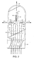
- FIG. 2 shows a schematic view of a preferred embodiment of a bending beam headlamp with a multi-filament bulb.
- FIG. 3 shows a schematic view of a preferred embodiment of an alternative multi-filament arrangement for a bending beam headlamp.
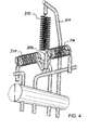
- FIG. 4 shows a detailed schematic view of an alternative embodiment of a multi-filament arrangement for a bending beam headlamp.
- FIG. 5 shows a perspective view of an alternative automotive headlamp bulb with a multi-filament arrangement for a bending beam headlamp.
- FIG. 6 shows a schematic view of an alternative embodiment of a multi-filament arrangement for a bending beam headlamp.
- FIG. 1 shows a schematic view of an advanced forward lighting system 10.
- FIG. 2 shows a schematic view of a preferred embodiment of a bending beam headlamp with a multi-filament bulb.
- a steering device 12 provides a signal 14 indicating desired movement of a vehicle relative to the road.
- the steering signal 14 is used by a controller 16 to alter the power supplied 18 to an improved lamp capsule 20 held in a reflector 22 directing light into a beam pattern 24.
- the lamp capsule 20 has a first filament 50 to generate a forward beam pattern 28.
- the lamp capsule 20 also has a second filament 60 to generate augmenting a first (right) side illumination 32.
- the lamp capsule 20 may also have a third filament 70 to generate augmenting second (left) side illumination 30.
- FIG. 2 shows a perspective view of a preferred embodiment of a bending beam headlamp with multi-filament capsule.
- the lamp includes an envelope with a light transmissive wall, defining an enclosed volume. In the enclosed volume is a plurality of filaments.
- the lamp is generally used with a reflector.
- the reflector 22 may be any of numerous headlamp reflectors. In particular, the reflector 22 may be a hollow, plastic shell with an aluminized interior surface shaping the light from the lamp into a vehicle headlamp beam.
- the first filament 50 extending along a first axis 52.
- the first filament 50 may be a straight wire extending as the axis 52; a wire coiled around the axis 52, a coiled coil extending along the axis 52, or similarly formed linearly extending filament structure.
- the first filament 50 is linearly extended along the first axis 52, and is symmetrically disposed about the first axis 52, to form an approximately cylindrical filament structure.
- the first filament has a first electrical connection 54 and a second electrical connection 56.
- the first filament is mechanically and electrically supported between a first support 58 and a second support 59.
- a second filament 60 extending along a second axis 62.
- the second filament 60 may also be a straight wire extending as the second axis 62, a wire coiled around the second axis 62, a coiled coil extending along the second axis 62, and so on in the same pattern.
- the second filament 60 is linearly extended along the second axis 62, and is symmetrically disposed about the second axis 62.
- the first axis 52 and the second axis 62 are in a common plane, but are not parallel.
- the second filament 60 then extends in a common plane (Actually the filaments are in a common parallel planar slice that is co-planar with their respective axes.
- the slice has a width equal to the filament diameter, but for convenience the filaments will be said to be in a common plane.) with the first filament 50, but in a direction with at least a component direction that is perpendicular to the first axis 52.
- the second filament has a first electrical connection 64 and a second electrical connection 66.
- the second filament 60 is coupled mechanically and electrically between the third support 68 and a fourth support 69.
- the second filament 60 forms a right angle with the first filament 50 at the rear end of the first filament 50.
- the second filament 60 is then substantially behind the first filament 50 (closer to the base 82), minimizing interference with the function of the first filament 50.
- a third filament 70 extending along a third axis 72.
- the third filament 70 may also be a straight wire extending as the third axis 72, a wire coiled around the third axis 72, a coiled coil extending along the third axis 72, and so on in the same pattern.
- the third filament 70 is linearly extended along the third axis 72, and is symmetrically disposed about the third axis 72.
- the first axis 52 and the third axis 72 are in a common plane but are not parallel.
- the third filament 70 then extends in a common plane (actually in a planar slice with a width of the filament diameter) with the first filament 50, but in a direction with at least a component direction that is perpendicular to the first axis 50.
- the third filament 70 has a first electrical connection 74 and a second electrical connection 76.
- the left side filament is coupled mechanically and electrically between the fifth support 78 and a sixth support 79.
- the third filament 70 may form a right angle with the first filament 50 at the rear end of the first filament 56.
- the third filament 70 is then substantially behind the first filament 50 (closer to the base 82) minimizing interference with the function of the first filament 50.
- the first support 58, second support 59, third support 68, fourth support 69, fifth support 78, sixth support 79 may be captured in a glass bridge 80, and then extended through a press sealed end 82 of the lamp envelope for electrical connection on the lamp exterior.
- the second support 59, fourth support 69 and sixth support 79 may be combined (pairwise or as a triple) to form a single support (common electrical supply).
- FIG. 3 shows a schematic view of a preferred embodiment of an alternative multi-filament arrangement for a bending beam headlamp.
- FIG. 4 shows a detailed schematic view of a preferred embodiment of a multi-filament arrangement for a bending beam headlamp.
- the first filament 100 is a coiled wire axially 102 aligned with a front end facing the field to be illuminated, and rear end facing a base 132.
- the first filament 100 is mechanically and electrically supported between a first support 104 and a second support 106.
- Roughly perpendicular to the first filament 100 is a right side filament 110.
- the right side filament 110 is a coiled wire whose axis 112 that is angled forward at an angle of 80 degrees to the first filament axis 102.
- the right side filament 110 is coupled mechanically and electrically between the second support 114 and in common with the second support 106.
- the right side filament 110 forms an 80-degree angle with the first filament 100 at the rear end of the first filament 100.
- Roughly perpendicular to the first filament 100 is a left side filament 120.
- the left side filament 120 is a coiled wire whose axis 122 is similarly angled forward at an angle of 80 degrees to the first filament axis 102.
- the left side filament 120 is coupled mechanically and electrically between a fourth support 124 and in common with the second support 106.
- the left side filament 120 forms an 80-degree angle with the first filament 100 at the rear end of the first filament 100.
- the first support 104, second support 106, third support 114, and fourth support 124 may be captured in a glass bridge 130, and then extended through a press sealed 132 end (base end) of the lamp envelope for electrical connection on the lamp exterior.
- the lamp is operated by supplying electrical energy to the first filament to generate light.
- the light generated by the first filament (50, 100) is then directed by the reflector to be centered about a desired point in the field to be illuminated.
- a first turning signal is generated that is used to signal the supply of electrical energy to the second filament (60, 120).
- the actual first turning signal may be generated as a function of one or more steering factors such as an absolute change, a rate of change, a duration of change, a time integrated change, some other signal indicating a change in the vehicle relative to the environment or a computed combination of such factors.
- the vehicle condition change signal is then used to drive the electrical energy supplied to the second filament (60, 120) or to the third filament (70, 110).
- the second filament (60, 120) located on the left of the first filament is turned on to generate light that is then reflected by the reflector to the right side (assuming an inverting reflector) of the beam pattern generated by the first filament (50, 100) and the reflector. It is understood there may be beam over lap between the reflected beam from the first filament, and the reflected beam from the second filament.
- the sensed actual turn on signal may be conditioned by other computed factors, such as the angle of turn, rate of turn, duration of turn angle, vehicle speed of or other measured or computed factors.
- the light from the second filament (60, 120) then further illuminates the right side of the field to be illuminated in the region where the vehicle is turning to.
- the third filament (70, 110) may be farther to the left of the first filament and the second filament (60, 120), and is sequentially illuminated when the turning factors indicate still more light is needed even farther to the right, for example when a particularly sharp turn is made and extra light is desired far to the side of the first beam pattern.
- the third filament (70, 110) may be located on the right side of the first filament (50, 100), which is on the opposite side of the first filament (50, 100) relative to the second filament (60, 120).
- the third filament (70, 110) may then be similarly connected to be illuminating when a left turn (opposite to a right turn) is sensed. Again the third filament (70, 110) may respond to the turn angle, the rate of turn, the duration of the turn a so on. In this way the main beam of the first filament is supplemented by the light from the second or third filaments, directed substantially in the same plane or planes, as is light for the first filament, but to a side of the center of the beam from the first filament.
- FIG. 5 shows a perspective view of an alternative automotive headlamp bulb with a multi-filament arrangement for a bending beam headlamp.
- FIG. 4 and 5 show a schematic side view of an alternative AFS lamp 300.
- the main filament 310 is axially aligned and centered in the forward end of the envelope 312 supported from two leads 314, 316.
- the right filament 318 and the left filament 320 are axially aligned, and offset sequentially rearward of the main filament 310 along the axis.
- the right filament 318 and left filament 320 may be share a lead with the main filament 310 for mechanical and electrical coupling.
- the right filament 318 and left filament 320 may be offset side to side from the main axis.
- the right filament 318 and left filament 320 may also be tilted with respect to the main axis.
- FIG. 6 shows a schematic view of an alternative AFS lamp 400.
- the main filament 410 is axially aligned in the forward end of the envelope 412 supported from two leads 414, 416.
- the second filament 418 and the third filament 420 are radially aligned in sequence rearward of the main filament 410.
- the second filament 418 and third filament 420 may be share a lead (416) with the main filament 410 for mechanical and electrical coupling.
- the second filament 418 and third filament 420 may be offset from the main axis.
- the second filament 418 and third filament 420 may also be tilted with respect to the main axis.
- the second filament is show to be perpendicular to the main filament 410, while the third filament 420 is shown to be at an angle to both the main filament 410 and the second filament 418.
- the main filament 410 is operated to generate a center beam pattern.
- the second filament 418 is additionally illuminated providing more light to one side of the center beam.
- the third filament 420 is illuminated providing additional light farther to one side of the main beam.
- the vehicle then may be equipped to either two headlamps each with center, right augmentation and left augmentation filaments; or one right headlamp with a center, soft right augmentation and hard right augmentation filaments and one left headlamp with center, soft left augmentation and hard left augmentation filaments.
- the main filament axis need not be axially centered along the main axis of the envelope, but may be radially offset from the main envelope axis. It is also understood that the lamp may be reoriented with respect to the field to be illuminated by restructuring the headlamp reflector accordingly. In general the second filament and the third filament may be positioned around the lamp axis in any position, given that the associated surrounding reflector directs the associated light appropriately to the right and left sides of the filed to be illuminated accordingly.
- One simple variation is to rotate the lamp 180 degrees, and rework the reflector to project the light from right (now left) and left (now right) side filaments across the beam axis line to the respective opposite sides of the illuminated field.
Landscapes
- Engineering & Computer Science (AREA)
- General Engineering & Computer Science (AREA)
- Non-Portable Lighting Devices Or Systems Thereof (AREA)
- Lighting Device Outwards From Vehicle And Optical Signal (AREA)
Abstract
Description
- The invention relates to electric lamps with a plurality of enclosed filaments.
- Advanced forward lighting headlamp systems (AFS) are being developed to light the road on the side a vehicle is turning to. The first AFS headlamp systems used one lamp and one reflector or projector lens. The beam control was achieved by rotating the entire lamp to the right or left with a stepper motor. This is a mechanically complex and expensive system. Alternative systems were devised using a first lamp to generate a forward beam and a second lamp to generate an augmenting side beam in response to a turning signal. By tuning between the two sources one can aim the beam. The two lamp AFS systems may use either or both two light sources, and two reflectors. The cost of the extra material for the lamps and the reflectors, the space and volume for the second lamp, and the additional labor in mounting, and aiming the duplicative systems makes the enhanced lighting system expensive.
- An incandescent lamp capsule may be made with an envelope having a light transmissive wall defining an enclosed volume, and a lamp axis. A first filament is positioned in the enclosed volume having a first filament axis. The first filament is oriented so the first filament axis is in an axial plane parallel with the lamp axis. A second filament is also positioned in the enclosed volume, defining a second filament axis. The second filament is oriented so the second filament axis is in the axial plane; and the second filament axis is not parallel to the first filament axis. A third filament is positioned in the enclosed volume, defining a third filament axis. The third filament is oriented so the third filament axis is in the axial plane with the first filament axis and the second filament axis. The third filament axis is not parallel to the first filament axis, and the third filament axis is not parallel to the second filament axis.
-
FIG. 1 shows a schematic view of an advanced forward lighting system. -
FIG. 2 shows a schematic view of a preferred embodiment of a bending beam headlamp with a multi-filament bulb. -
FIG. 3 shows a schematic view of a preferred embodiment of an alternative multi-filament arrangement for a bending beam headlamp. -
FIG. 4 shows a detailed schematic view of an alternative embodiment of a multi-filament arrangement for a bending beam headlamp. -
FIG. 5 shows a perspective view of an alternative automotive headlamp bulb with a multi-filament arrangement for a bending beam headlamp. -
FIG. 6 shows a schematic view of an alternative embodiment of a multi-filament arrangement for a bending beam headlamp. -
FIG. 1 shows a schematic view of an advanced forward lighting system 10.FIG. 2 shows a schematic view of a preferred embodiment of a bending beam headlamp with a multi-filament bulb. Asteering device 12 provides asignal 14 indicating desired movement of a vehicle relative to the road. Thesteering signal 14 is used by acontroller 16 to alter the power supplied 18 to an improvedlamp capsule 20 held in areflector 22 directing light into abeam pattern 24. Thelamp capsule 20 has afirst filament 50 to generate aforward beam pattern 28. Thelamp capsule 20 also has asecond filament 60 to generate augmenting a first (right)side illumination 32. Thelamp capsule 20 may also have athird filament 70 to generate augmenting second (left)side illumination 30. -
FIG. 2 shows a perspective view of a preferred embodiment of a bending beam headlamp with multi-filament capsule. The lamp includes an envelope with a light transmissive wall, defining an enclosed volume. In the enclosed volume is a plurality of filaments. The lamp is generally used with a reflector. Thereflector 22 may be any of numerous headlamp reflectors. In particular, thereflector 22 may be a hollow, plastic shell with an aluminized interior surface shaping the light from the lamp into a vehicle headlamp beam. - Enclosed in the envelope volume is a
first filament 50 extending along afirst axis 52. Thefirst filament 50 may be a straight wire extending as theaxis 52; a wire coiled around theaxis 52, a coiled coil extending along theaxis 52, or similarly formed linearly extending filament structure. In general, thefirst filament 50 is linearly extended along thefirst axis 52, and is symmetrically disposed about thefirst axis 52, to form an approximately cylindrical filament structure. The first filament has a firstelectrical connection 54 and a secondelectrical connection 56. The first filament is mechanically and electrically supported between afirst support 58 and asecond support 59. - Enclosed in the volume is a
second filament 60 extending along asecond axis 62. Thesecond filament 60 may also be a straight wire extending as thesecond axis 62, a wire coiled around thesecond axis 62, a coiled coil extending along thesecond axis 62, and so on in the same pattern. In general, thesecond filament 60 is linearly extended along thesecond axis 62, and is symmetrically disposed about thesecond axis 62. Thefirst axis 52 and thesecond axis 62 are in a common plane, but are not parallel. Thesecond filament 60 then extends in a common plane (Actually the filaments are in a common parallel planar slice that is co-planar with their respective axes. The slice has a width equal to the filament diameter, but for convenience the filaments will be said to be in a common plane.) with thefirst filament 50, but in a direction with at least a component direction that is perpendicular to thefirst axis 52. The second filament has a firstelectrical connection 64 and a secondelectrical connection 66. Thesecond filament 60 is coupled mechanically and electrically between thethird support 68 and afourth support 69. In one preferred embodiment, thesecond filament 60 forms a right angle with thefirst filament 50 at the rear end of thefirst filament 50. Thesecond filament 60 is then substantially behind the first filament 50 (closer to the base 82), minimizing interference with the function of thefirst filament 50. - Enclosed in the volume is a
third filament 70 extending along athird axis 72. Thethird filament 70 may also be a straight wire extending as thethird axis 72, a wire coiled around thethird axis 72, a coiled coil extending along thethird axis 72, and so on in the same pattern. In general, thethird filament 70 is linearly extended along thethird axis 72, and is symmetrically disposed about thethird axis 72. Thefirst axis 52 and thethird axis 72 are in a common plane but are not parallel. Thethird filament 70 then extends in a common plane (actually in a planar slice with a width of the filament diameter) with thefirst filament 50, but in a direction with at least a component direction that is perpendicular to thefirst axis 50. Thethird filament 70 has a firstelectrical connection 74 and a secondelectrical connection 76. The left side filament is coupled mechanically and electrically between thefifth support 78 and asixth support 79. Thethird filament 70 may form a right angle with thefirst filament 50 at the rear end of thefirst filament 56. Thethird filament 70 is then substantially behind the first filament 50 (closer to the base 82) minimizing interference with the function of thefirst filament 50. - The
first support 58,second support 59,third support 68,fourth support 69,fifth support 78,sixth support 79 may be captured in aglass bridge 80, and then extended through a press sealedend 82 of the lamp envelope for electrical connection on the lamp exterior. Thesecond support 59,fourth support 69 andsixth support 79 may be combined (pairwise or as a triple) to form a single support (common electrical supply). -
FIG. 3 shows a schematic view of a preferred embodiment of an alternative multi-filament arrangement for a bending beam headlamp.FIG. 4 shows a detailed schematic view of a preferred embodiment of a multi-filament arrangement for a bending beam headlamp. Thefirst filament 100 is a coiled wire axially 102 aligned with a front end facing the field to be illuminated, and rear end facing abase 132. Thefirst filament 100 is mechanically and electrically supported between afirst support 104 and asecond support 106. Roughly perpendicular to thefirst filament 100 is aright side filament 110. Theright side filament 110 is a coiled wire whoseaxis 112 that is angled forward at an angle of 80 degrees to thefirst filament axis 102. Theright side filament 110 is coupled mechanically and electrically between thesecond support 114 and in common with thesecond support 106. Theright side filament 110 forms an 80-degree angle with thefirst filament 100 at the rear end of thefirst filament 100. Roughly perpendicular to thefirst filament 100 is aleft side filament 120. Theleft side filament 120 is a coiled wire whoseaxis 122 is similarly angled forward at an angle of 80 degrees to thefirst filament axis 102. Theleft side filament 120 is coupled mechanically and electrically between afourth support 124 and in common with thesecond support 106. Theleft side filament 120 forms an 80-degree angle with thefirst filament 100 at the rear end of thefirst filament 100. Thefirst support 104,second support 106,third support 114, andfourth support 124 may be captured in aglass bridge 130, and then extended through a press sealed 132 end (base end) of the lamp envelope for electrical connection on the lamp exterior. - The lamp is operated by supplying electrical energy to the first filament to generate light. The light generated by the first filament (50, 100) is then directed by the reflector to be centered about a desired point in the field to be illuminated. When the vehicle is steered under a first condition to a one side relative to the beam generated by the first filament (50, 100), a first turning signal is generated that is used to signal the supply of electrical energy to the second filament (60, 120). The actual first turning signal may be generated as a function of one or more steering factors such as an absolute change, a rate of change, a duration of change, a time integrated change, some other signal indicating a change in the vehicle relative to the environment or a computed combination of such factors. The vehicle condition change signal is then used to drive the electrical energy supplied to the second filament (60, 120) or to the third filament (70, 110). For example, if the vehicle is turned to the right, the second filament (60, 120) located on the left of the first filament is turned on to generate light that is then reflected by the reflector to the right side (assuming an inverting reflector) of the beam pattern generated by the first filament (50, 100) and the reflector. It is understood there may be beam over lap between the reflected beam from the first filament, and the reflected beam from the second filament. The sensed actual turn on signal may be conditioned by other computed factors, such as the angle of turn, rate of turn, duration of turn angle, vehicle speed of or other measured or computed factors. The light from the second filament (60, 120) then further illuminates the right side of the field to be illuminated in the region where the vehicle is turning to. The third filament (70, 110) may be farther to the left of the first filament and the second filament (60, 120), and is sequentially illuminated when the turning factors indicate still more light is needed even farther to the right, for example when a particularly sharp turn is made and extra light is desired far to the side of the first beam pattern. Alternatively, the third filament (70, 110) may be located on the right side of the first filament (50, 100), which is on the opposite side of the first filament (50, 100) relative to the second filament (60, 120). The third filament (70, 110) may then be similarly connected to be illuminating when a left turn (opposite to a right turn) is sensed. Again the third filament (70, 110) may respond to the turn angle, the rate of turn, the duration of the turn a so on. In this way the main beam of the first filament is supplemented by the light from the second or third filaments, directed substantially in the same plane or planes, as is light for the first filament, but to a side of the center of the beam from the first filament.
FIG. 5 shows a perspective view of an alternative automotive headlamp bulb with a multi-filament arrangement for a bending beam headlamp. -
FIG. 4 and5 show a schematic side view of analternative AFS lamp 300. Themain filament 310 is axially aligned and centered in the forward end of theenvelope 312 supported from twoleads right filament 318 and theleft filament 320 are axially aligned, and offset sequentially rearward of themain filament 310 along the axis. Theright filament 318 and leftfilament 320 may be share a lead with themain filament 310 for mechanical and electrical coupling. Theright filament 318 and leftfilament 320 may be offset side to side from the main axis. Theright filament 318 and leftfilament 320 may also be tilted with respect to the main axis. -
FIG. 6 shows a schematic view of analternative AFS lamp 400. Themain filament 410 is axially aligned in the forward end of theenvelope 412 supported from twoleads second filament 418 and thethird filament 420 are radially aligned in sequence rearward of themain filament 410. Thesecond filament 418 andthird filament 420 may be share a lead (416) with themain filament 410 for mechanical and electrical coupling. Thesecond filament 418 andthird filament 420 may be offset from the main axis. Thesecond filament 418 andthird filament 420 may also be tilted with respect to the main axis. The second filament is show to be perpendicular to themain filament 410, while thethird filament 420 is shown to be at an angle to both themain filament 410 and thesecond filament 418. In operation, with both augmenting filaments (418, 420) on one side of themain filament 410, themain filament 410 is operated to generate a center beam pattern. With a moderate turn to one side, thesecond filament 418 is additionally illuminated providing more light to one side of the center beam. With a greater turning, thethird filament 420 is illuminated providing additional light farther to one side of the main beam. The vehicle then may be equipped to either two headlamps each with center, right augmentation and left augmentation filaments; or one right headlamp with a center, soft right augmentation and hard right augmentation filaments and one left headlamp with center, soft left augmentation and hard left augmentation filaments. - It is understood the main filament axis need not be axially centered along the main axis of the envelope, but may be radially offset from the main envelope axis. It is also understood that the lamp may be reoriented with respect to the field to be illuminated by restructuring the headlamp reflector accordingly. In general the second filament and the third filament may be positioned around the lamp axis in any position, given that the associated surrounding reflector directs the associated light appropriately to the right and left sides of the filed to be illuminated accordingly. One simple variation is to rotate the lamp 180 degrees, and rework the reflector to project the light from right (now left) and left (now right) side filaments across the beam axis line to the respective opposite sides of the illuminated field. More complex redirections can be achieved with a vertical orientation, that is changing from a 3 o'clock to 9 o'clock orientation to a 12 o'clock to 6 o'clock orientation or any intermediate orientation. While there have been shown and described what are at present considered to be the preferred embodiments of the invention, it will be apparent to those skilled in the art that various changes and modifications can be made herein without departing from the scope of the invention defined by the appended claims.
Claims (17)
- A incandescent multi-filament lamp capsule (20; 412) having a base (82; 132), comprising:an envelope having a light transmissive wall defining an enclosed volume;a first filament (50; 100; 410) positioned in the enclosed volume and having a first filament axis (52; 102),a second filament (60; 120; 418) positioned in the enclosed volume and defining a second filament axis (62; 122), anda third filament (70; 110; 420) positioned in the enclosed volume and defining a third filament axis (72; 112), andelectrical connections (18) sealed through the wall and joined respectively to the first, the second and the third filament to selectively power the respectively the first filament, the second filament and the third filament,wherein the first filament axis (52; 102) is directed in a forward direction, the second filament axis (60; 120; 418) is in a common plane with the first filament axis (52; 102) and extending with a directional component perpendicular to the first filament axis (52; 102); and the third filament axis (70; 110; 420) is in the same common plane with the first filament axis (52; 102) and the second filament axis (62; 122); the third filament axis (70; 110; 420) extending with a directional component perpendicular to the first filament axis (52; 102).
- An incandescent multi-filament lamp capsule (20; 412) in claim 1
wherein the lamp has a lamp axis (52; 102);
the first filament (50; 100; 410) is oriented so the first filament axis (52; 102) is in an axial plane parallel with the lamp axis (52; 102);
the second filament (60; 120; 418) is oriented so the second filament axis (62; 122) is in the axial plane; and the second filament axis (62; 122) is not parallel to the first filament axis (52; 102);
the third filament (70; 110; 420) is oriented so the third filament axis( 72; 112) is in the axial plane with the first filament axis (52; 102) and the second filament axis (62; 122), and the third filament axis (72; 112) is not parallel to the first filament axis (52; 102) and the third filament axis (72; 112) is not parallel to the second filament axis (62; 122). - The incandescent multi-filament lamp capsule (20; 412) in claim 2, wherein the second filament (60; 120; 418) is substantially behind the first filament (50; 100; 410).
- The incandescent multi-filament lamp capsule (20; 412) in claim 3, wherein the third filament (70; 110; 420) is substantially behind the first filament (50; 100; 410).
- The incandescent multi-filament lamp capsule (20; 412) in claim 2, wherein the second filament (60; 120; 418) is on a side of the first filament (50; 100; 410), and the third filament (70; 110; 420) is on the same side of the first filament. (50; 100; 410).
- The incandescent multi-filament lamp capsule (20; 412) in claim 5, wherein the second filament (60; 120; 418) is substantially behind the first filament (50; 100; 410).
- The incandescent multi-filament lamp capsule (20; 412) in claim 6, wherein the third filament (70; 110; 420) is substantially behind the first filament (50; 100; 410).
- The incandescent multi-filament lamp capsule (20; 412) in claim 2, wherein the second filament (60; 120; 418) is oriented so the second filament axis (62; 122) is perpendicular to the first filament axis (52; 102).
- The incandescent multi-filament lamp capsule (20; 412) in claim 8, wherein the third filament (70; 110; 420) is oriented so the third filament axis (72; 112) is perpendicular to the first filament axis (52; 102).
- The incandescent multi-filament lamp capsule (20; 412) in claim 2, wherein the second filament (60; 120; 418) is on a first side of the first filament (50; 100; 410); and the third filament (70; 110; 420) is on a second side of the same side of the first filament (50; 100; 410), opposite the first side of the first filament (50; 100; 410).
- The incandescent multi-filament lamp capsule (20; 412) in claim 10, wherein the second filament (60; 120; 418) is substantially behind the first filament (50; 100; 410).
- The incandescent multi-filament lamp capsule (20; 412) in claim 11, wherein the third filament (70; 110; 420) is substantially behind the first filament (50; 100; 410).
- The incandescent multi-filament lamp capsule (20; 412) in claim 10, wherein the second filament (60; 120; 418) is oriented so the second filament axis (62; 122) is perpendicular to the first filament axis. (52; 102)
- The incandescent multi-filament lamp capsule in (20; 412) claim 13, wherein the third filament (70; 110; 420) is oriented so the third filament axis (72; 112) is perpendicular to the first filament axis (52; 102).
- The incandescent multi-filament lamp capsule (20; 412) in claim 2, having electrical connections sealed through the wall and joined respectively to the first filament (50; 100; 410), the second filament (60; 120; 418) and the third filament (70; 110; 420) to selectively power respectively the first filament (50; 100; 410), the second filament (60; 120; 418) and the third filament (70; 110; 420).
- The incandescent multi-filament lamp capsule in (20; 412) claim 15, wherein the first filament (50; 100; 410) has a first electrical connection, and a second electrical connection;
the second filament (60; 120; 418) has a first electrical connection, and a second electrical connection;
the third filament (70; 110; 420) has a first electrical connection, and a second electrical connection; wherein
the respective first electrical connections of the first filament (50; 100; 410), the second filament (60; 120; 418), and the third filament (70; 110; 420) have a common electrical connection; and wherein;
the respective second electrical connections of the first filament (50; 100; 410), the second filament (60; 120; 418), and the third filament (70; 110; 420) have no common electrical connection. - A method of operating an incandescent multi-filament lamp capsule (20; 412) in accordance with anyone of the preceding claims, comprising the steps of providing a first electrical power to the first filament (50; 100; 410) on a first condition to generate light directed substantially centered on an axis (52; 102) as a main beam to the field to be illuminated;
providing a second condition signal in response to a change in a vehicle condition relative to the exterior environment; and
in response to the second condition signal, simultaneously providing electrical power to the second filament (60; 120; 418) to generate light directed about a beam to a side of the main beam axis (52; 102).
Applications Claiming Priority (2)
| Application Number | Priority Date | Filing Date | Title |
|---|---|---|---|
| US11/904,890 US7670037B2 (en) | 2007-09-28 | 2007-09-28 | Bending beam headlamp with multi-filament bulb |
| EP08016827A EP2043132B1 (en) | 2007-09-28 | 2008-09-25 | Bending beam headlamp with multi-filament bulb |
Related Parent Applications (2)
| Application Number | Title | Priority Date | Filing Date |
|---|---|---|---|
| EP08016827.1 Division | 2008-09-25 | ||
| EP08016827A Division EP2043132B1 (en) | 2007-09-28 | 2008-09-25 | Bending beam headlamp with multi-filament bulb |
Publications (2)
| Publication Number | Publication Date |
|---|---|
| EP2482306A1 true EP2482306A1 (en) | 2012-08-01 |
| EP2482306B1 EP2482306B1 (en) | 2014-06-25 |
Family
ID=40350023
Family Applications (2)
| Application Number | Title | Priority Date | Filing Date |
|---|---|---|---|
| EP08016827A Not-in-force EP2043132B1 (en) | 2007-09-28 | 2008-09-25 | Bending beam headlamp with multi-filament bulb |
| EP12002400.5A Not-in-force EP2482306B1 (en) | 2007-09-28 | 2008-09-25 | Method of operating a multi-filament bulb for bending beam headlamp |
Family Applications Before (1)
| Application Number | Title | Priority Date | Filing Date |
|---|---|---|---|
| EP08016827A Not-in-force EP2043132B1 (en) | 2007-09-28 | 2008-09-25 | Bending beam headlamp with multi-filament bulb |
Country Status (4)
| Country | Link |
|---|---|
| US (1) | US7670037B2 (en) |
| EP (2) | EP2043132B1 (en) |
| KR (1) | KR101786068B1 (en) |
| CN (1) | CN101398141B (en) |
Families Citing this family (5)
| Publication number | Priority date | Publication date | Assignee | Title |
|---|---|---|---|---|
| US9396925B1 (en) | 2015-02-27 | 2016-07-19 | Osram Sylvania Inc. | Partially coated vehicle lamp capsule |
| USD757305S1 (en) | 2015-02-27 | 2016-05-24 | Osram Sylvania Inc. | Lamp capsule with coating |
| DE102016006390A1 (en) * | 2016-05-24 | 2017-11-30 | Audi Ag | Lighting device for a motor vehicle to increase the visibility of an obstacle |
| US11057963B2 (en) * | 2017-10-06 | 2021-07-06 | Applied Materials, Inc. | Lamp infrared radiation profile control by lamp filament design and positioning |
| CN209672092U (en) * | 2019-03-14 | 2019-11-22 | 漳州立达信光电子科技有限公司 | A kind of LED lamp |
Citations (5)
| Publication number | Priority date | Publication date | Assignee | Title |
|---|---|---|---|---|
| GB332458A (en) * | 1929-09-23 | 1930-07-24 | Burton Stafford Fox | Method of headlighting and an electric lamp for use in connection with the same |
| US1954075A (en) * | 1931-05-23 | 1934-04-10 | Gen Motors Corp | Lighting circuit |
| US2152836A (en) * | 1937-06-12 | 1939-04-04 | Bovey Thomas | Lamp for the headlights of vehicles |
| US2565757A (en) * | 1946-06-05 | 1951-08-28 | Electric Auto Lite Co | Multibeam head lamp incorporating gradually fluted reflector and pluraality of filaments |
| US2791713A (en) * | 1954-10-21 | 1957-05-07 | Gen Electric | Light projection device |
Family Cites Families (9)
| Publication number | Priority date | Publication date | Assignee | Title |
|---|---|---|---|---|
| US1793398A (en) * | 1928-01-11 | 1931-02-17 | Hamberger John | Electric lamp |
| FR745839A (en) * | 1931-11-18 | 1933-05-17 | ||
| US2214472A (en) * | 1938-10-06 | 1940-09-10 | Gen Electric | Electric incandescent lamp |
| DE2248899A1 (en) * | 1971-10-08 | 1973-04-12 | Magneti Marelli Spa | HEADLIGHT WITH DEFLECTION OF THE BEAM, ESPECIALLY FOR VEHICLES |
| DE2254058A1 (en) * | 1972-11-04 | 1974-05-16 | Licentia Gmbh | LAMP FOR A MOTOR VEHICLE HEADLIGHT |
| US3886400A (en) * | 1973-05-11 | 1975-05-27 | Gary G Dill | Multi-filament light bulb and the like |
| US4638408A (en) * | 1984-06-28 | 1987-01-20 | Wetherington Aubrey D | Automobile headlight-fog light combination |
| DE19809296A1 (en) * | 1998-03-05 | 1999-09-09 | Gribov | Automobile lighting device for optimum illumination of road ahead |
| US6955439B2 (en) * | 2003-02-21 | 2005-10-18 | Guide Corporation | Dual filament static bending lamp |
-
2007
- 2007-09-28 US US11/904,890 patent/US7670037B2/en not_active Expired - Fee Related
-
2008
- 2008-09-24 KR KR1020080093607A patent/KR101786068B1/en not_active Expired - Fee Related
- 2008-09-25 EP EP08016827A patent/EP2043132B1/en not_active Not-in-force
- 2008-09-25 EP EP12002400.5A patent/EP2482306B1/en not_active Not-in-force
- 2008-09-28 CN CN2008101687557A patent/CN101398141B/en not_active Expired - Fee Related
Patent Citations (5)
| Publication number | Priority date | Publication date | Assignee | Title |
|---|---|---|---|---|
| GB332458A (en) * | 1929-09-23 | 1930-07-24 | Burton Stafford Fox | Method of headlighting and an electric lamp for use in connection with the same |
| US1954075A (en) * | 1931-05-23 | 1934-04-10 | Gen Motors Corp | Lighting circuit |
| US2152836A (en) * | 1937-06-12 | 1939-04-04 | Bovey Thomas | Lamp for the headlights of vehicles |
| US2565757A (en) * | 1946-06-05 | 1951-08-28 | Electric Auto Lite Co | Multibeam head lamp incorporating gradually fluted reflector and pluraality of filaments |
| US2791713A (en) * | 1954-10-21 | 1957-05-07 | Gen Electric | Light projection device |
Also Published As
| Publication number | Publication date |
|---|---|
| CN101398141B (en) | 2013-02-06 |
| US20090086501A1 (en) | 2009-04-02 |
| EP2043132A2 (en) | 2009-04-01 |
| EP2043132A3 (en) | 2011-05-04 |
| US7670037B2 (en) | 2010-03-02 |
| KR101786068B1 (en) | 2017-10-16 |
| EP2043132B1 (en) | 2012-06-27 |
| EP2482306B1 (en) | 2014-06-25 |
| KR20090033025A (en) | 2009-04-01 |
| CN101398141A (en) | 2009-04-01 |
Similar Documents
| Publication | Publication Date | Title |
|---|---|---|
| US7670037B2 (en) | Bending beam headlamp with multi-filament bulb | |
| US8672525B2 (en) | Projection head lamp assembly for vehicle | |
| JP2001067909A (en) | Projector type headlamp | |
| JPH01243301A (en) | Improved lighting apparatus employing optical fiber | |
| KR20130096668A (en) | Automotive headlamp having a beam changing assembly | |
| US20220074568A1 (en) | Lighting apparatus for vehicles | |
| CN106152007B (en) | lights for vehicles | |
| US4480296A (en) | Two-filament lamp for automobile headlight | |
| JP2002133913A (en) | Vehicle headlights | |
| US7722210B2 (en) | Automotive lamp and reflector for low beam and advanced forward lighting system | |
| CN105351860A (en) | Light collecting device and headlamp provided with light splitting structure | |
| US6742919B2 (en) | Discharge lamp and headlight for a motor vehicle | |
| US6913367B2 (en) | Vehicle headlamp | |
| JPS62254355A (en) | Head light for automobile and so forth | |
| JP2007149683A (en) | Optical modules used in automotive lighting or signaling devices | |
| JP5027246B2 (en) | Shielding device | |
| US20040165373A1 (en) | Dual filament static bending lamp | |
| US6616315B2 (en) | Headlight of the elliptical type for a motor vehicle capable of generating several light beams | |
| US20070182326A1 (en) | Filament lamp comprising two coiled filaments and a lamp assembly | |
| JP2000251520A (en) | Lamp for automobile | |
| CN109099382A (en) | It is provided with the lighting device for vehicle of LED illumination module | |
| JP2005335698A (en) | Method for controlling vehicle floodlight device and vehicle floodlight device having cornering illumination function | |
| US9523474B2 (en) | Headlamp for vehicle | |
| JP2000003610A (en) | Increasing / decreasing light headlight with gas discharge lamp | |
| JP2002279804A (en) | Lamp |
Legal Events
| Date | Code | Title | Description |
|---|---|---|---|
| PUAI | Public reference made under article 153(3) epc to a published international application that has entered the european phase |
Free format text: ORIGINAL CODE: 0009012 |
|
| 17P | Request for examination filed |
Effective date: 20120425 |
|
| AC | Divisional application: reference to earlier application |
Ref document number: 2043132 Country of ref document: EP Kind code of ref document: P |
|
| AK | Designated contracting states |
Kind code of ref document: A1 Designated state(s): AT BE BG CH CY CZ DE DK EE ES FI FR GB GR HR HU IE IS IT LI LT LU LV MC MT NL NO PL PT RO SE SI SK TR |
|
| 17Q | First examination report despatched |
Effective date: 20130726 |
|
| GRAP | Despatch of communication of intention to grant a patent |
Free format text: ORIGINAL CODE: EPIDOSNIGR1 |
|
| INTG | Intention to grant announced |
Effective date: 20140109 |
|
| GRAS | Grant fee paid |
Free format text: ORIGINAL CODE: EPIDOSNIGR3 |
|
| GRAA | (expected) grant |
Free format text: ORIGINAL CODE: 0009210 |
|
| AC | Divisional application: reference to earlier application |
Ref document number: 2043132 Country of ref document: EP Kind code of ref document: P |
|
| AK | Designated contracting states |
Kind code of ref document: B1 Designated state(s): AT BE BG CH CY CZ DE DK EE ES FI FR GB GR HR HU IE IS IT LI LT LU LV MC MT NL NO PL PT RO SE SI SK TR |
|
| REG | Reference to a national code |
Ref country code: GB Ref legal event code: FG4D |
|
| REG | Reference to a national code |
Ref country code: CH Ref legal event code: EP |
|
| REG | Reference to a national code |
Ref country code: AT Ref legal event code: REF Ref document number: 675146 Country of ref document: AT Kind code of ref document: T Effective date: 20140715 |
|
| REG | Reference to a national code |
Ref country code: IE Ref legal event code: FG4D |
|
| REG | Reference to a national code |
Ref country code: DE Ref legal event code: R096 Ref document number: 602008033053 Country of ref document: DE Effective date: 20140807 |
|
| PG25 | Lapsed in a contracting state [announced via postgrant information from national office to epo] |
Ref country code: CY Free format text: LAPSE BECAUSE OF FAILURE TO SUBMIT A TRANSLATION OF THE DESCRIPTION OR TO PAY THE FEE WITHIN THE PRESCRIBED TIME-LIMIT Effective date: 20140625 Ref country code: NO Free format text: LAPSE BECAUSE OF FAILURE TO SUBMIT A TRANSLATION OF THE DESCRIPTION OR TO PAY THE FEE WITHIN THE PRESCRIBED TIME-LIMIT Effective date: 20140925 Ref country code: GR Free format text: LAPSE BECAUSE OF FAILURE TO SUBMIT A TRANSLATION OF THE DESCRIPTION OR TO PAY THE FEE WITHIN THE PRESCRIBED TIME-LIMIT Effective date: 20140926 Ref country code: FI Free format text: LAPSE BECAUSE OF FAILURE TO SUBMIT A TRANSLATION OF THE DESCRIPTION OR TO PAY THE FEE WITHIN THE PRESCRIBED TIME-LIMIT Effective date: 20140625 Ref country code: LT Free format text: LAPSE BECAUSE OF FAILURE TO SUBMIT A TRANSLATION OF THE DESCRIPTION OR TO PAY THE FEE WITHIN THE PRESCRIBED TIME-LIMIT Effective date: 20140625 |
|
| REG | Reference to a national code |
Ref country code: AT Ref legal event code: MK05 Ref document number: 675146 Country of ref document: AT Kind code of ref document: T Effective date: 20140625 |
|
| REG | Reference to a national code |
Ref country code: NL Ref legal event code: VDEP Effective date: 20140625 |
|
| REG | Reference to a national code |
Ref country code: LT Ref legal event code: MG4D |
|
| PG25 | Lapsed in a contracting state [announced via postgrant information from national office to epo] |
Ref country code: HR Free format text: LAPSE BECAUSE OF FAILURE TO SUBMIT A TRANSLATION OF THE DESCRIPTION OR TO PAY THE FEE WITHIN THE PRESCRIBED TIME-LIMIT Effective date: 20140625 Ref country code: LV Free format text: LAPSE BECAUSE OF FAILURE TO SUBMIT A TRANSLATION OF THE DESCRIPTION OR TO PAY THE FEE WITHIN THE PRESCRIBED TIME-LIMIT Effective date: 20140625 Ref country code: SE Free format text: LAPSE BECAUSE OF FAILURE TO SUBMIT A TRANSLATION OF THE DESCRIPTION OR TO PAY THE FEE WITHIN THE PRESCRIBED TIME-LIMIT Effective date: 20140625 |
|
| PG25 | Lapsed in a contracting state [announced via postgrant information from national office to epo] |
Ref country code: SK Free format text: LAPSE BECAUSE OF FAILURE TO SUBMIT A TRANSLATION OF THE DESCRIPTION OR TO PAY THE FEE WITHIN THE PRESCRIBED TIME-LIMIT Effective date: 20140625 Ref country code: PT Free format text: LAPSE BECAUSE OF FAILURE TO SUBMIT A TRANSLATION OF THE DESCRIPTION OR TO PAY THE FEE WITHIN THE PRESCRIBED TIME-LIMIT Effective date: 20141027 Ref country code: ES Free format text: LAPSE BECAUSE OF FAILURE TO SUBMIT A TRANSLATION OF THE DESCRIPTION OR TO PAY THE FEE WITHIN THE PRESCRIBED TIME-LIMIT Effective date: 20140625 Ref country code: RO Free format text: LAPSE BECAUSE OF FAILURE TO SUBMIT A TRANSLATION OF THE DESCRIPTION OR TO PAY THE FEE WITHIN THE PRESCRIBED TIME-LIMIT Effective date: 20140625 Ref country code: CZ Free format text: LAPSE BECAUSE OF FAILURE TO SUBMIT A TRANSLATION OF THE DESCRIPTION OR TO PAY THE FEE WITHIN THE PRESCRIBED TIME-LIMIT Effective date: 20140625 Ref country code: EE Free format text: LAPSE BECAUSE OF FAILURE TO SUBMIT A TRANSLATION OF THE DESCRIPTION OR TO PAY THE FEE WITHIN THE PRESCRIBED TIME-LIMIT Effective date: 20140625 |
|
| PG25 | Lapsed in a contracting state [announced via postgrant information from national office to epo] |
Ref country code: AT Free format text: LAPSE BECAUSE OF FAILURE TO SUBMIT A TRANSLATION OF THE DESCRIPTION OR TO PAY THE FEE WITHIN THE PRESCRIBED TIME-LIMIT Effective date: 20140625 Ref country code: IS Free format text: LAPSE BECAUSE OF FAILURE TO SUBMIT A TRANSLATION OF THE DESCRIPTION OR TO PAY THE FEE WITHIN THE PRESCRIBED TIME-LIMIT Effective date: 20141025 Ref country code: NL Free format text: LAPSE BECAUSE OF FAILURE TO SUBMIT A TRANSLATION OF THE DESCRIPTION OR TO PAY THE FEE WITHIN THE PRESCRIBED TIME-LIMIT Effective date: 20140625 Ref country code: PL Free format text: LAPSE BECAUSE OF FAILURE TO SUBMIT A TRANSLATION OF THE DESCRIPTION OR TO PAY THE FEE WITHIN THE PRESCRIBED TIME-LIMIT Effective date: 20140625 |
|
| REG | Reference to a national code |
Ref country code: DE Ref legal event code: R097 Ref document number: 602008033053 Country of ref document: DE |
|
| PG25 | Lapsed in a contracting state [announced via postgrant information from national office to epo] |
Ref country code: IT Free format text: LAPSE BECAUSE OF FAILURE TO SUBMIT A TRANSLATION OF THE DESCRIPTION OR TO PAY THE FEE WITHIN THE PRESCRIBED TIME-LIMIT Effective date: 20140625 Ref country code: LU Free format text: LAPSE BECAUSE OF FAILURE TO SUBMIT A TRANSLATION OF THE DESCRIPTION OR TO PAY THE FEE WITHIN THE PRESCRIBED TIME-LIMIT Effective date: 20140925 Ref country code: MC Free format text: LAPSE BECAUSE OF FAILURE TO SUBMIT A TRANSLATION OF THE DESCRIPTION OR TO PAY THE FEE WITHIN THE PRESCRIBED TIME-LIMIT Effective date: 20140625 Ref country code: DK Free format text: LAPSE BECAUSE OF FAILURE TO SUBMIT A TRANSLATION OF THE DESCRIPTION OR TO PAY THE FEE WITHIN THE PRESCRIBED TIME-LIMIT Effective date: 20140625 |
|
| REG | Reference to a national code |
Ref country code: CH Ref legal event code: PL |
|
| PLBE | No opposition filed within time limit |
Free format text: ORIGINAL CODE: 0009261 |
|
| STAA | Information on the status of an ep patent application or granted ep patent |
Free format text: STATUS: NO OPPOSITION FILED WITHIN TIME LIMIT |
|
| 26N | No opposition filed |
Effective date: 20150326 |
|
| REG | Reference to a national code |
Ref country code: IE Ref legal event code: MM4A |
|
| PG25 | Lapsed in a contracting state [announced via postgrant information from national office to epo] |
Ref country code: LI Free format text: LAPSE BECAUSE OF NON-PAYMENT OF DUE FEES Effective date: 20140930 Ref country code: CH Free format text: LAPSE BECAUSE OF NON-PAYMENT OF DUE FEES Effective date: 20140930 |
|
| PG25 | Lapsed in a contracting state [announced via postgrant information from national office to epo] |
Ref country code: IE Free format text: LAPSE BECAUSE OF NON-PAYMENT OF DUE FEES Effective date: 20140925 |
|
| PG25 | Lapsed in a contracting state [announced via postgrant information from national office to epo] |
Ref country code: SI Free format text: LAPSE BECAUSE OF FAILURE TO SUBMIT A TRANSLATION OF THE DESCRIPTION OR TO PAY THE FEE WITHIN THE PRESCRIBED TIME-LIMIT Effective date: 20140625 |
|
| PG25 | Lapsed in a contracting state [announced via postgrant information from national office to epo] |
Ref country code: BG Free format text: LAPSE BECAUSE OF FAILURE TO SUBMIT A TRANSLATION OF THE DESCRIPTION OR TO PAY THE FEE WITHIN THE PRESCRIBED TIME-LIMIT Effective date: 20140625 |
|
| PG25 | Lapsed in a contracting state [announced via postgrant information from national office to epo] |
Ref country code: MT Free format text: LAPSE BECAUSE OF FAILURE TO SUBMIT A TRANSLATION OF THE DESCRIPTION OR TO PAY THE FEE WITHIN THE PRESCRIBED TIME-LIMIT Effective date: 20140625 |
|
| PG25 | Lapsed in a contracting state [announced via postgrant information from national office to epo] |
Ref country code: BE Free format text: LAPSE BECAUSE OF FAILURE TO SUBMIT A TRANSLATION OF THE DESCRIPTION OR TO PAY THE FEE WITHIN THE PRESCRIBED TIME-LIMIT Effective date: 20140625 Ref country code: HU Free format text: LAPSE BECAUSE OF FAILURE TO SUBMIT A TRANSLATION OF THE DESCRIPTION OR TO PAY THE FEE WITHIN THE PRESCRIBED TIME-LIMIT; INVALID AB INITIO Effective date: 20080925 Ref country code: TR Free format text: LAPSE BECAUSE OF FAILURE TO SUBMIT A TRANSLATION OF THE DESCRIPTION OR TO PAY THE FEE WITHIN THE PRESCRIBED TIME-LIMIT Effective date: 20140625 |
|
| REG | Reference to a national code |
Ref country code: FR Ref legal event code: PLFP Year of fee payment: 9 |
|
| REG | Reference to a national code |
Ref country code: FR Ref legal event code: PLFP Year of fee payment: 10 |
|
| REG | Reference to a national code |
Ref country code: FR Ref legal event code: PLFP Year of fee payment: 11 |
|
| PGFP | Annual fee paid to national office [announced via postgrant information from national office to epo] |
Ref country code: DE Payment date: 20180920 Year of fee payment: 11 Ref country code: FR Payment date: 20180925 Year of fee payment: 11 |
|
| PGFP | Annual fee paid to national office [announced via postgrant information from national office to epo] |
Ref country code: GB Payment date: 20180919 Year of fee payment: 11 |
|
| REG | Reference to a national code |
Ref country code: DE Ref legal event code: R119 Ref document number: 602008033053 Country of ref document: DE |
|
| PG25 | Lapsed in a contracting state [announced via postgrant information from national office to epo] |
Ref country code: DE Free format text: LAPSE BECAUSE OF NON-PAYMENT OF DUE FEES Effective date: 20200401 |
|
| GBPC | Gb: european patent ceased through non-payment of renewal fee |
Effective date: 20190925 |
|
| PG25 | Lapsed in a contracting state [announced via postgrant information from national office to epo] |
Ref country code: FR Free format text: LAPSE BECAUSE OF NON-PAYMENT OF DUE FEES Effective date: 20190930 Ref country code: GB Free format text: LAPSE BECAUSE OF NON-PAYMENT OF DUE FEES Effective date: 20190925 |