EP2482035A2 - Electronic systems for locating objects - Google Patents
Electronic systems for locating objects Download PDFInfo
- Publication number
- EP2482035A2 EP2482035A2 EP20120152092 EP12152092A EP2482035A2 EP 2482035 A2 EP2482035 A2 EP 2482035A2 EP 20120152092 EP20120152092 EP 20120152092 EP 12152092 A EP12152092 A EP 12152092A EP 2482035 A2 EP2482035 A2 EP 2482035A2
- Authority
- EP
- European Patent Office
- Prior art keywords
- orientation
- sections
- pmr
- calculated
- distance
- Prior art date
- Legal status (The legal status is an assumption and is not a legal conclusion. Google has not performed a legal analysis and makes no representation as to the accuracy of the status listed.)
- Withdrawn
Links
- 238000012545 processing Methods 0.000 claims description 28
- 238000000034 method Methods 0.000 claims description 18
- 230000015654 memory Effects 0.000 claims description 9
- 230000008859 change Effects 0.000 claims description 8
- YCLAMANSVUJYPT-UHFFFAOYSA-L aluminum chloride hydroxide hydrate Chemical compound O.[OH-].[Al+3].[Cl-] YCLAMANSVUJYPT-UHFFFAOYSA-L 0.000 description 25
- 230000033001 locomotion Effects 0.000 description 11
- 238000010586 diagram Methods 0.000 description 4
- 238000004891 communication Methods 0.000 description 3
- 238000012986 modification Methods 0.000 description 3
- 230000004048 modification Effects 0.000 description 3
- 238000005516 engineering process Methods 0.000 description 2
- 230000008569 process Effects 0.000 description 2
- 238000007792 addition Methods 0.000 description 1
- 230000005540 biological transmission Effects 0.000 description 1
- 238000012937 correction Methods 0.000 description 1
- 230000003287 optical effect Effects 0.000 description 1
- 230000004044 response Effects 0.000 description 1
- 239000000126 substance Substances 0.000 description 1
- 238000006467 substitution reaction Methods 0.000 description 1
- 238000012546 transfer Methods 0.000 description 1
Images


Classifications
-
- G—PHYSICS
- G01—MEASURING; TESTING
- G01C—MEASURING DISTANCES, LEVELS OR BEARINGS; SURVEYING; NAVIGATION; GYROSCOPIC INSTRUMENTS; PHOTOGRAMMETRY OR VIDEOGRAMMETRY
- G01C21/00—Navigation; Navigational instruments not provided for in groups G01C1/00 - G01C19/00
- G01C21/38—Electronic maps specially adapted for navigation; Updating thereof
- G01C21/3863—Structures of map data
- G01C21/387—Organisation of map data, e.g. version management or database structures
- G01C21/3874—Structures specially adapted for data searching and retrieval
-
- G—PHYSICS
- G01—MEASURING; TESTING
- G01C—MEASURING DISTANCES, LEVELS OR BEARINGS; SURVEYING; NAVIGATION; GYROSCOPIC INSTRUMENTS; PHOTOGRAMMETRY OR VIDEOGRAMMETRY
- G01C21/00—Navigation; Navigational instruments not provided for in groups G01C1/00 - G01C19/00
- G01C21/10—Navigation; Navigational instruments not provided for in groups G01C1/00 - G01C19/00 by using measurements of speed or acceleration
- G01C21/12—Navigation; Navigational instruments not provided for in groups G01C1/00 - G01C19/00 by using measurements of speed or acceleration executed aboard the object being navigated; Dead reckoning
-
- G—PHYSICS
- G01—MEASURING; TESTING
- G01C—MEASURING DISTANCES, LEVELS OR BEARINGS; SURVEYING; NAVIGATION; GYROSCOPIC INSTRUMENTS; PHOTOGRAMMETRY OR VIDEOGRAMMETRY
- G01C21/00—Navigation; Navigational instruments not provided for in groups G01C1/00 - G01C19/00
- G01C21/26—Navigation; Navigational instruments not provided for in groups G01C1/00 - G01C19/00 specially adapted for navigation in a road network
- G01C21/28—Navigation; Navigational instruments not provided for in groups G01C1/00 - G01C19/00 specially adapted for navigation in a road network with correlation of data from several navigational instruments
- G01C21/30—Map- or contour-matching
Definitions
- a conventional inertial navigation system includes a dead reckoning (DR) system for calculating a position and an orientation of a moving object according to motion tracking information.
- the DR system can obtain the motion tracking information from a motion sensor such as a gyroscope and a milemeter.
- a motion sensor such as a gyroscope and a milemeter.
- the gyroscope and the milemeter can introduce errors that reduce the accuracy of the calculated position and orientation of the moving object.
- a database for a set of orientation-matched road (OMR) sections is searched according to a calculated orientation of an object and orientations of road sections stored in the database.
- the OMR sections are searched for a position-matched road (PMR) set according to a calculated position of the object and positions of the OMR sections.
- the PMR set includes one or more PMR sections.
- the object is located using the PMR set.
- FIG. 1 illustrates a block diagram of an example of a positioning system, in accordance with one embodiment of the present invention.
- FIG. 2 illustrates a diagram of part of an example of a map, in accordance with one embodiment of the present invention.
- FIG. 3 illustrates a flowchart of examples of operations performed by a positioning system, in accordance with one embodiment of the present invention.
- FIG. 4 illustrates a flowchart of examples of operations performed by a positioning system, in accordance with one embodiment of the present invention.
- FIG. 5 illustrates a flowchart of examples of operations performed by a positioning system, in accordance with one embodiment of the present invention.
- FIG. 6 illustrates a flowchart of examples of operations performed by a positioning system, in accordance with one embodiment of the present invention.
- Embodiments described herein may be discussed in the general context of computer-executable instructions residing on some form of computer-usable medium, such as program modules, executed by one or more computers or other devices.
- program modules include routines, programs, objects, components, data structures, etc., that perform particular tasks or implement particular abstract data types.
- the functionality of the program modules may be combined or distributed as desired in various embodiments.
- Computer-usable media may comprise computer storage media and communication media.
- Computer storage media includes volatile and nonvolatile, removable and non-removable media implemented in any method or technology for storage of information such as computer-readable instructions, data structures, program modules or other data.
- Computer storage media includes, but is not limited to, random access memory (RAM), read only memory (ROM), electrically erasable programmable ROM (EEPROM), flash memory or other memory technology, compact disk ROM (CD-ROM), digital versatile disks (DVDs) or other optical storage, magnetic cassettes, magnetic tape, magnetic disk storage or other magnetic storage devices, or any other medium that can be used to store the desired information.
- Communication media can embody computer-readable instructions, data structures, program modules or other data and includes any information delivery media.
- communication media includes wired media such as a wired network or direct-wired connection, and wireless media such as acoustic, radio frequency (RF), infrared and other wireless media. Combinations of any of the above should also be included within the scope of computer-readable media.
- the present invention provides a positioning system for locating a moving object.
- the positioning system calculates a position of the moving object and an orientation of the moving object, and compares the calculated position and orientation with information about road sections on an electronic map.
- the positioning system further selects a matched reference road section from the road sections on the electronic map, and corrects the calculated position and the calculated orientation based on the matched reference road section.
- FIG. 1 illustrates a block diagram of an example of a positioning system 100, e.g., an inertial navigation system/global positioning system (INS/GPS), in accordance with one embodiment of the present invention.
- the positioning system 100 includes a map system 102 and a position calculation system 112.
- the position calculation system 112 can calculate a position of a moving object (not shown), e.g., a vehicle.
- the position calculation system 112 can receive GPS signals from satellites (not shown) and calculate a current position of the moving object according to the GPS signals. If the GPS signals are too weak to be received, the position calculation system 112 can also calculate a current position of the moving object according to an initial position of the moving object and a motion track of the moving object.
- the position calculation system 112 can correct the calculated position of the moving object according to reference information from the map system 102.
- the map system 102 stores a navigation map that includes information about road sections.
- a navigation map includes multiple roads, and each road is divided into several sections.
- Each section of the road e.g., referred to as road section, has an orientation and a position.
- the map system 102 can store the orientation and position information of road sections on the navigation map.
- the map system 102 can receive the calculated or corrected position information of the moving object from the position calculation system 112 and display the position of the moving object on the navigation map.
- the map system 102 can further search the navigation map for reference information, and provide the reference information to the position calculation system 112.
- the map system 102 includes a map information storage unit 104, a processing unit 106, and memory 108.
- the map information storage unit 104 stores a database that includes information for a navigation map, e.g., position information and orientation information about road sections.
- the memory 108 stores computer-executable software, e.g., computer-readable instructions.
- the processing unit 106 executes the computer-executable software, e.g., the computer-readable instructions, such that the processing unit 106 searches the map information database for a set of orientation-matched road (OMR) sections according to a calculated orientation O CAL of the moving object and orientations O RS of road sections stored in the map information database.
- OMR orientation-matched road
- the processing unit 106 also executes the computer-executable software, e.g., the computer-readable instructions, such that the processing unit 106 searches the OMR sections for a position-matched road (PMR) set according to a calculated position P CAL of the moving object and positions P RS of the OMR sections.
- the PMR set includes one or more PMR sections and is used to locate the moving object.
- the processing unit 106 searches for the OMR sections by comparing a difference ⁇ DIF between the calculated orientation O CAL of the moving object and the orientation O RS of each road section stored in the map information database with an orientation offset reference ⁇ REF . If the difference ⁇ DIF between the calculated orientation O CAL and an orientation O RS of a road section is less than the orientation offset reference ⁇ REF , e.g.
- the processing unit 106 also searches for one or more PMR sections by comparing a distance reference D REF with a distance D CRS from the calculated position P CAL of the moving object to each of the OMR sections. If the distance D CRS from the calculated position P CAL to an OMR section is less than the distance reference D REF , then that OMR section is a PMR section.
- the processing unit 106 increases the distance reference D REF to another value D' REF .
- the processing unit 106 re-searches the OMR sections for one or more PMR sections by comparing the distance reference D' REF with the distance D CRS from the calculated position P CAL of the moving object to each of the OMR sections.
- the distance reference D REF can be initially set to 10m.
- the processing unit 106 If the processing unit 106 cannot find any PMR section within 10m, the processing unit 106 increases the distance reference D REF to 30m, or 50m, or 70m, etc., and repeats the comparison until one or more PMR sections are found. In one embodiment, the distance reference D REF has a limit, e.g., 70m. If the processing unit 106 cannot find any PMR section within that limit, then the processing unit 106 can terminate the search. On the other hand, if one or more PMR sections are found, then the map system 102 provides information for the one or more PMR sections to the position calculation system 112.
- the position calculation system 112 includes a GPS module 118 and a processor 120 that includes a navigation aid module 114 and a dead reckoning (DR) module 116.
- the GPS module 118 can calculate the position of the moving object according to GPS signals if the GPS signals are strong enough.
- the DR module 116 can calculate the position of the moving object according to the initial position of the moving object and a motion track of the moving object if the GPS signals are not strong enough.
- the navigation aid module 114 can correct the position of the moving object that is calculated by the DR module 116.
- the GPS module 118 can receive GPS signals via an antenna 124 and calculate a position of the moving object according to the GPS signals.
- the GPS module 118 can provide the position information of the moving object to the map system 102 to display the position of the moving object on the navigation map.
- the GPS module 118 can also provide the position information for the moving object to the processor 120.
- the DR module 116 in the processor 120 can calculate a position P CAL of the moving object according to initial position information for the moving object, e.g. the position information provided by the GPS module 118 or position information pre-stored in the DR module 116, and according to the motion track of the moving object.
- the motion track includes the change in the orientation of the moving object and includes the running distance of the moving object.
- the motion track of the moving object can be sensed by a motion sensor 122, e.g., a gyroscope, a milemeter, etc.
- the DR module 116 can also calculate an orientation O CAL of movement of the moving object according to the motion track.
- An interface 110 coupled to the processor 120 can receive reference information from the map system 102 periodically, and can transfer the reference information to the processor 120.
- the reference information indicates a reference orientation O REF and a reference position P REF of a reference road section, shown on the navigation map, where the moving object is located.
- the processor 120 can further compare the calculated position P CAL and the calculated orientation O CAL with the reference orientation O REF and the reference position P REF , respectively.
- the processor 120 can request the map system 102 for the aforementioned one or more PMR sections.
- the processor 120 can receive information indicative of the one or more PMR sections via the interface 110 and use that information to correct the calculated orientation O CAL and the calculated position P CAL .
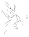
- FIG. 2 illustrates a diagram of part of an example of a map 200, in accordance with one embodiment of the present invention.
- FIG. 2 is described in combination with FIG. 1 .
- the map 200 includes multiple road sections. Each road section includes a position P 1 , P 2 , ... (shown as a dot) and an orientation O 1 , O 2 , ... (shown as an arrow).
- P CAL represents a position of the moving object calculated by the DR module 116
- O CAL represents an orientation of the moving object calculated by the DR module 116.
- the processor 120 generates a request to search the map system 102.
- the request includes an orientation O CAL and a position P CAL calculated by the DR module 116.
- the processing unit 106 in response to the request, searches the map 200 for a first set of OMR sections by comparing a difference between the calculated orientation O CAL and each orientation O 1 , O 2 , ... with an orientation offset reference ⁇ REF , e.g., 60°.
- an orientation offset reference ⁇ REF e.g. 60°.
- the differences between the calculated orientation O CAL and the orientations O 1 , O 2 , O 3 , O 4 , O 5 , O 6 , O 9 and O 10 are less than 60°, therefore the first set of OMR sections include road sections (P 1 , O 1 ), (P 2 , O 2 ), (P 3 , O 3 ), (P 4 , O 4 ), (P 5 , O 5 ), (P 6 , O 6 ), (P 9 , O 9 ) and (P 10 , O 10 ).
- the processing unit 106 further searches for one or more PMR sections by comparing a distance from the calculated position P CAL to each member of the first set of OMR sections with a distance reference D REF .
- the distance reference D REF can be initially set to 10m, for example.
- the processing unit 106 can then increase the distance reference D REF to 30m, for example.
- the processing unit 106 searches the first set of OMR sections for one or more PMR sections within 30m. If one or more PMR sections are found, the map system 102 provides information for the one or more PMR sections to the position calculation system 112; otherwise, the processing unit 106 increases the distance reference D REF again, e.g., to 50m.
- the processing unit 106 can increase the distance reference D REF step by step until one or more PMR sections are found. However, the distance reference D REF has a maximum limit, e.g., 70m. If no PMR section is found within the maximum limit, then the processing unit 106 terminates the search and may generate an output signal indicating failure.
- the map system 102 when one or more PMR sections are found, provides information for the PMR sections to the position calculation system 112.
- the processor 120 selects a matched reference road (MRR) section from the PMR sections according to a distance from the calculated position P CAL of the moving object to each member of the PMR sections and the total number of PMR sections.
- MRR matched reference road
- the distance from the calculated position P CAL to the position P 3 may be less than the distance reference D REF , while the distances from the calculated position P CAL to the other positions P 1 , P 2 , P 4 , P 57 P 6 , P 9 and P 10 may be greater than the distance reference D REF . Accordingly, only one PMR section, e.g., the road section (P 3 , O 3 ), is found.
- the navigation aid module 114 can use the road section (P 3 , O 3 ) as an MRR section, and correct the calculated position P CAL and the calculated orientation O CAL to the position P 3 and the orientation O 3 , respectively.
- the DR module 116 includes a register unit to store currently calculated information, e.g., position and orientation information, of the moving object.
- the navigation aid module 114 can erase the currently calculated information in the register unit and write the information indicative of the position P 3 and the orientation O 3 into the register unit.
- the distances from the calculated position P CAL to the positions P 3 and P 5 may be less than the distance reference D REF , while the distances from the calculated position P CAL to the other positions P 1 , P 2 , P 4 , P 6 , P 9 and P 10 may be greater than the distance reference D REF .
- two PMR sections e.g., the road sections (P 3 , O 3 ) and (P 5 , O 5 ), are found.
- the processor 120 can compare the distance
- the navigation aid module 114 selects the road section that has the shorter distance from the calculated position P CAL as an MRR section, e.g., the road section (P 3 , O 3 ), and corrects the calculated position P CAL and the calculated orientation O CAL according to the selected MRR section.
- the number of PMR sections may be greater than two.
- the processor 120 can discard the currently received information for the PMR sections.
- the processor 120 can generate a new search request when a predefined time interval expires or when a running distance of the moving object exceeds a preset reference.
- the new request includes a newly calculated orientation O' CAL and a newly calculated position P' CAL of the moving object.
- the processing unit 106 receives the new request and searches the database, e.g., the map 200, in the map information storage unit 104 for a second set of OMR sections based on the newly calculated orientation O' CAL .
- the processing unit 106 further searches the second set of OMR sections for one or more PMR sections based on the newly calculated position P' CAL .
- the processing unit 106 performs the search steps in a similar manner as described above.
- the positioning system 100 can reduce mistakes such as correcting the calculated position and the calculated orientation of the moving object using the wrong road section.
- FIG. 3 illustrates a flowchart 300 of examples of operations performed by the position calculation system 112, e.g., by the processor 120, in accordance with one embodiment of the present invention.
- FIG. 3 is described in combination with FIG. 1 .
- the processor 120 performs the flowchart 300 to send the map system 102 a request to search for one or more PMR sections (hereinafter, a search request).
- the processor 120 attempts to get initial information for the moving object.
- the initial information includes an initial position P INT of the moving object and an initial time t INT corresponding to the initial position P INT .
- the initial information for the moving object can be pre-stored in the DR module 116 or the navigation aid module 114.
- the GPS module 118 receives GPS signals
- the GPS module 118 generates position information for the moving object to the processor 120.
- the processor 120 can use the position information previously generated by the GPS module 118 as the initial position information.
- the processor 120 can also use position information previously calculated by the DR module 116 as the initial position information.
- the processor 120 can also uses position information previously corrected by the navigation aid module 114 as the initial position information.
- the processor 120 compares a running distance of the moving object with a preset reference, e.g., 10m.
- the running distance is the distance from the initial position P INT to a currently calculated position P CAL . If the running distance
- the processor 120 counts the running time of the moving object, measured from the initial time t INT to a current time t CUR . If the running time
- a preset time reference e.g. 3 minutes
- the processor 120 can receive reference information e.g., indicative of a reference orientation O REF and a reference position P REF , for a reference road section, shown on the navigation map, where the moving object is located.
- the processor 120 compares a currently calculated position P CAL of the moving object with the reference position P REF and compares a currently calculated orientation O CAL of the moving object with the reference orientation O REF .
- the processor 120 compares the distance from the currently calculated position P CAL to the reference position P REF with a predetermined distance threshold, e.g., 10m.
- the processor 120 compares the difference between the currently calculated orientation O CAL and the reference orientation O REF with a predetermined orientation threshold, e.g., 10°. If the difference
- a predetermined orientation threshold e.g. 10°.
- the processor 120 can send a search request to the map system 102 for various distance thresholds.
- the processor 120 can also send a search request to the map system 102 at various time intervals.
- the processor 120 also sends a search request to the map system 102.
- the map system 102 receives the search request and provides one or more PMR sections to the processor 120 to correct the calculated information for the moving object.
- FIG. 4 illustrates a flowchart 400 of examples of operations performed by the map system 102, in accordance with one embodiment of the present invention. FIG. 4 is described in combination with FIG. 1 and FIG. 2 . In one embodiment, the map system 102 performs the flowchart 400 to provide one or more PMR sections to the processor 120.
- the map system 102 detects a search request. If the map system 102 receives a search request, the map system 102 performs step 404 to search the database in the map information storage unit 104 for a set of OMR sections. At step 406, the map system 102 searches the OMR sections for one or more PMR sections. If one or more PMR sections are found, then the map system 102 provides the orientation information and the position information for the one or more PMR sections to the position calculation system 112. The map system 102 can perform the search for the OMR sections and the search for the one or more PMR sections in a manner similar to those described in relation to FIG. 1 and FIG. 2 .
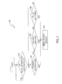
- FIG. 5 illustrates a flowchart 500 of examples of operations performed by the position calculation system 112, in accordance with one embodiment of the present invention.
- FIG. 5 is described in combination with FIG. 1 and FIG. 2 .
- the position calculation system 112 performs the flowchart 500 to correct a calculated position P CAL of and a calculated orientation O CAL of the moving object.
- the processor 120 receives information for one or more PMR sections from the map system 102 and checks whether a matched road count, e.g., the number of PMR sections, is greater than zero and less than three. If the matched road count is greater than zero and less than three, the flowchart 500 goes to step 504; otherwise, the flowchart 500 ends.
- a matched road count e.g., the number of PMR sections
- the processor 120 selects an MRR section from the PMR sections.
- the processor 120 performs the selecting step in a similar manner to that described in relation to FIG. 2 .
- the processor 120 sets an orientation offset threshold ⁇ TH according to a pattern of change in the calculated orientation O CAL of the moving object, and sets a distance threshold D TH according to a pattern of change in the calculated position P CAL of the moving object. More specifically, if the change in the calculated orientation O CAL in a predefined time interval increases, then the processor 120 increases the orientation offset threshold ⁇ TH .
- the orientation offset threshold ⁇ TH can be set to 15°.
- the orientation offset threshold ⁇ TH can be set to 20°.
- the moving object can run substantially straight on a road, e.g., a turning angle of the moving object within a predefined time interval is less than 20°. If a straight-running distance of the moving object during the time when the moving object runs substantially straight on a road increases, the processor 120 increases the distance threshold D TH .
- the distance threshold D TH can be set to 50m. If the straight-running distance of the moving object is greater than 150m, the distance threshold D TH can be set to 70m.
- the processor 120 performs steps 510 and 512 in parallel.
- the processor 120 determines whether a distance D CRS from the calculated position P CAL of the moving object to the reference position P REF of the MRR section is within a first distance range, e.g., less the distance threshold D TH .
- the processor 120 also determines whether a difference ⁇ DIF between the calculated orientation O CAL of the moving object and the reference orientation O REF of the MRR section is within a first orientation offset range, e.g., from 3° to the orientation offset threshold ⁇ TH .
- the processor 120 performs step 514; otherwise, the processor 120 performs step 518.
- the navigation aid module 114 corrects the calculated orientation O CAL to the reference orientation O REF , e.g., by writing information for the reference orientation O REF into the DR module 116 to replace the information for the calculated orientation O CAL .
- the processor 120 determines whether the distance D CRS is within a second distance range, e.g., from 5m to the distance threshold D TH , and whether the difference ⁇ DIF is within a second orientation offset range, e.g., less than the orientation offset threshold ⁇ TH . If the distance D CRS is within the second distance range and the difference ⁇ DIF is within the second orientation offset range, then the processor 120 performs step 516; otherwise, the processor 120 performs step 518.
- the navigation aid module 114 corrects the calculated position P CAL to the reference position P REF , e.g., by writing the information for the reference position P REF into the DR module 116 to replace the information for the calculated position P CAL .
- the processor 120 determines whether the position and orientation of the moving object currently stored in the DR module 116 is correct. For example, if a distance D CRS between the reference position P REF and the currently stored position of the moving object is less than a predetermined threshold, e.g., 10m, and a difference ⁇ DIF between the reference orientation O REF and the currently stored orientation of the moving object is less than a predetermined threshold, e.g., 10°, then the currently stored position and orientation information of the moving object is considered to be correct. If the currently stored information of the moving object is correct, then the flowchart 500 goes to step 520; otherwise, the flowchart 500 ends.
- a predetermined threshold e.g. 10m
- a difference ⁇ DIF between the reference orientation O REF and the currently stored orientation of the moving object is less than a predetermined threshold, e.g. 10°
- the position calculation system 112 updates a start point flag. More specifically, the position calculation system 112 instructs the map system 102 to update the position of the moving object shown on the navigation map according to the information for the moving object currently stored in the DR module 116. The position calculation system 112 can also replace the previously obtained initial information for the moving object with the currently stored information.
- FIG. 6 illustrates a flowchart 600 of examples of operations performed by the positioning system 100, in accordance with one embodiment of the present invention.
- FIG. 6 is described in combination with FIG. 1 , FIG. 2 , FIG. 3 , FIG. 4 and FIG. 5 .
- the positioning system 100 searches a database in the map information storage unit 104 for a set of OMR sections according to a calculated orientation O CAL of a moving object and orientations O RS of road sections stored in the map information database.
- the positioning system 100 searches the OMR sections for a PMR set that includes one or more PMR sections according to a calculated position P CAL of the moving object and positions P RS of the OMR sections.
- the positioning system 100 locates the moving object using the PMR set.
Landscapes
- Engineering & Computer Science (AREA)
- Radar, Positioning & Navigation (AREA)
- Remote Sensing (AREA)
- Automation & Control Theory (AREA)
- Physics & Mathematics (AREA)
- General Physics & Mathematics (AREA)
- Databases & Information Systems (AREA)
- Navigation (AREA)
Abstract
Description
- The present application is a continuation-in-part of
U.S. Patent Application Serial No. 12/495,454, filed June 30, 2009 201110034870.7, filed on Jan. 27, 2011 - A conventional inertial navigation system includes a dead reckoning (DR) system for calculating a position and an orientation of a moving object according to motion tracking information. The DR system can obtain the motion tracking information from a motion sensor such as a gyroscope and a milemeter. However, the gyroscope and the milemeter can introduce errors that reduce the accuracy of the calculated position and orientation of the moving object.
- In one embodiment, a database for a set of orientation-matched road (OMR) sections is searched according to a calculated orientation of an object and orientations of road sections stored in the database. The OMR sections are searched for a position-matched road (PMR) set according to a calculated position of the object and positions of the OMR sections. The PMR set includes one or more PMR sections. The object is located using the PMR set.
- Features and advantages of embodiments of the claimed subject matter will become apparent as the following detailed description proceeds, and upon reference to the drawings, wherein like numerals depict like parts, and in which:
-
FIG. 1 illustrates a block diagram of an example of a positioning system, in accordance with one embodiment of the present invention. -
FIG. 2 illustrates a diagram of part of an example of a map, in accordance with one embodiment of the present invention. -
FIG. 3 illustrates a flowchart of examples of operations performed by a positioning system, in accordance with one embodiment of the present invention. -
FIG. 4 illustrates a flowchart of examples of operations performed by a positioning system, in accordance with one embodiment of the present invention. -
FIG. 5 illustrates a flowchart of examples of operations performed by a positioning system, in accordance with one embodiment of the present invention. -
FIG. 6 illustrates a flowchart of examples of operations performed by a positioning system, in accordance with one embodiment of the present invention. - Reference will now be made in detail to the embodiments of the present invention. While the invention will be described in conjunction with these embodiments, it will be understood that they are not intended to limit the invention to these embodiments. On the contrary, the invention is intended to cover alternatives, modifications and equivalents, which may be included within the spirit and scope of the invention as defined by the appended claims.
- Embodiments described herein may be discussed in the general context of computer-executable instructions residing on some form of computer-usable medium, such as program modules, executed by one or more computers or other devices. Generally, program modules include routines, programs, objects, components, data structures, etc., that perform particular tasks or implement particular abstract data types. The functionality of the program modules may be combined or distributed as desired in various embodiments.
- Some portions of the detailed descriptions which follow are presented in terms of procedures, logic blocks, processing and other symbolic representations of operations on data bits within a computer memory. These descriptions and representations are the means used by those skilled in the data processing arts to most effectively convey the substance of their work to others skilled in the art. In the present application, a procedure, logic block, process, or the like, is conceived to be a self-consistent sequence of steps or instructions leading to a desired result. The steps are those requiring physical manipulations of physical quantities. Usually, although not necessarily, these quantities take the form of electrical or magnetic signals capable of being stored, transferred, combined, compared, and otherwise manipulated in a computer system.
- It should be borne in mind, however, that all of these and similar terms are to be associated with the appropriate physical quantities and are merely convenient labels applied to these quantities. Unless specifically stated otherwise as apparent from the following discussions, it is appreciated that throughout the present application, discussions utilizing the terms such as "searching," "locating," "comparing," "increasing," "selecting," "correcting," "setting" or the like, refer to the actions and processes of a computer system, or similar electronic computing device, that manipulates and transforms data represented as physical (electronic) quantities within the computer system's registers and memories into other data similarly represented as physical quantities within the computer system memories or registers or other such information storage, transmission or display devices.
- By way of example, and not limitation, computer-usable media may comprise computer storage media and communication media. Computer storage media includes volatile and nonvolatile, removable and non-removable media implemented in any method or technology for storage of information such as computer-readable instructions, data structures, program modules or other data. Computer storage media includes, but is not limited to, random access memory (RAM), read only memory (ROM), electrically erasable programmable ROM (EEPROM), flash memory or other memory technology, compact disk ROM (CD-ROM), digital versatile disks (DVDs) or other optical storage, magnetic cassettes, magnetic tape, magnetic disk storage or other magnetic storage devices, or any other medium that can be used to store the desired information.
- Communication media can embody computer-readable instructions, data structures, program modules or other data and includes any information delivery media. By way of example, and not limitation, communication media includes wired media such as a wired network or direct-wired connection, and wireless media such as acoustic, radio frequency (RF), infrared and other wireless media. Combinations of any of the above should also be included within the scope of computer-readable media.
- Furthermore, in the following detailed description of the present invention, numerous specific details are set forth in order to provide a thorough understanding of the present invention. However, it will be recognized by one of ordinary skill in the art that the present invention may be practiced without these specific details. In other instances, well known methods, procedures, components, and circuits have not been described in detail as not to unnecessarily obscure aspects of the present invention.
- In one embodiment, the present invention provides a positioning system for locating a moving object. The positioning system calculates a position of the moving object and an orientation of the moving object, and compares the calculated position and orientation with information about road sections on an electronic map. The positioning system further selects a matched reference road section from the road sections on the electronic map, and corrects the calculated position and the calculated orientation based on the matched reference road section.
-
FIG. 1 illustrates a block diagram of an example of apositioning system 100, e.g., an inertial navigation system/global positioning system (INS/GPS), in accordance with one embodiment of the present invention. Thepositioning system 100 includes amap system 102 and aposition calculation system 112. Theposition calculation system 112 can calculate a position of a moving object (not shown), e.g., a vehicle. Theposition calculation system 112 can receive GPS signals from satellites (not shown) and calculate a current position of the moving object according to the GPS signals. If the GPS signals are too weak to be received, theposition calculation system 112 can also calculate a current position of the moving object according to an initial position of the moving object and a motion track of the moving object. Furthermore, theposition calculation system 112 can correct the calculated position of the moving object according to reference information from themap system 102. In one embodiment, themap system 102 stores a navigation map that includes information about road sections. For example, a navigation map includes multiple roads, and each road is divided into several sections. Each section of the road, e.g., referred to as road section, has an orientation and a position. Themap system 102 can store the orientation and position information of road sections on the navigation map. Themap system 102 can receive the calculated or corrected position information of the moving object from theposition calculation system 112 and display the position of the moving object on the navigation map. Themap system 102 can further search the navigation map for reference information, and provide the reference information to theposition calculation system 112. - More specifically, in one embodiment, the
map system 102 includes a mapinformation storage unit 104, aprocessing unit 106, andmemory 108. The mapinformation storage unit 104 stores a database that includes information for a navigation map, e.g., position information and orientation information about road sections. Thememory 108 stores computer-executable software, e.g., computer-readable instructions. Theprocessing unit 106 executes the computer-executable software, e.g., the computer-readable instructions, such that theprocessing unit 106 searches the map information database for a set of orientation-matched road (OMR) sections according to a calculated orientation OCAL of the moving object and orientations ORS of road sections stored in the map information database. Theprocessing unit 106 also executes the computer-executable software, e.g., the computer-readable instructions, such that theprocessing unit 106 searches the OMR sections for a position-matched road (PMR) set according to a calculated position PCAL of the moving object and positions PRS of the OMR sections. The PMR set includes one or more PMR sections and is used to locate the moving object. - In one embodiment, the
processing unit 106 searches for the OMR sections by comparing a difference θDIF between the calculated orientation OCAL of the moving object and the orientation ORS of each road section stored in the map information database with an orientation offset reference θREF. If the difference θDIF between the calculated orientation OCAL and an orientation ORS of a road section is less than the orientation offset reference θREF, e.g. |OCAL-ORS|<θREF, then that road section is an OMR section. Theprocessing unit 106 also searches for one or more PMR sections by comparing a distance reference DREF with a distance DCRS from the calculated position PCAL of the moving object to each of the OMR sections. If the distance DCRS from the calculated position PCAL to an OMR section is less than the distance reference DREF, then that OMR section is a PMR section. - In one embodiment, on one hand, if the result of the search for one or more PMR sections is a failure, e.g., no PMR section is found, then the
processing unit 106 increases the distance reference DREF to another value D'REF. Theprocessing unit 106 re-searches the OMR sections for one or more PMR sections by comparing the distance reference D'REF with the distance DCRS from the calculated position PCAL of the moving object to each of the OMR sections. By way of example, the distance reference DREF can be initially set to 10m. If theprocessing unit 106 cannot find any PMR section within 10m, theprocessing unit 106 increases the distance reference DREF to 30m, or 50m, or 70m, etc., and repeats the comparison until one or more PMR sections are found. In one embodiment, the distance reference DREF has a limit, e.g., 70m. If theprocessing unit 106 cannot find any PMR section within that limit, then theprocessing unit 106 can terminate the search. On the other hand, if one or more PMR sections are found, then themap system 102 provides information for the one or more PMR sections to theposition calculation system 112. - In one embodiment, the
position calculation system 112 includes aGPS module 118 and aprocessor 120 that includes anavigation aid module 114 and a dead reckoning (DR)module 116. TheGPS module 118 can calculate the position of the moving object according to GPS signals if the GPS signals are strong enough. TheDR module 116 can calculate the position of the moving object according to the initial position of the moving object and a motion track of the moving object if the GPS signals are not strong enough. Thenavigation aid module 114 can correct the position of the moving object that is calculated by theDR module 116. - By way of example, the
GPS module 118 can receive GPS signals via anantenna 124 and calculate a position of the moving object according to the GPS signals. TheGPS module 118 can provide the position information of the moving object to themap system 102 to display the position of the moving object on the navigation map. TheGPS module 118 can also provide the position information for the moving object to theprocessor 120. TheDR module 116 in theprocessor 120 can calculate a position PCAL of the moving object according to initial position information for the moving object, e.g. the position information provided by theGPS module 118 or position information pre-stored in theDR module 116, and according to the motion track of the moving object. The motion track includes the change in the orientation of the moving object and includes the running distance of the moving object. The motion track of the moving object can be sensed by amotion sensor 122, e.g., a gyroscope, a milemeter, etc. TheDR module 116 can also calculate an orientation OCAL of movement of the moving object according to the motion track. Aninterface 110 coupled to theprocessor 120 can receive reference information from themap system 102 periodically, and can transfer the reference information to theprocessor 120. The reference information indicates a reference orientation OREF and a reference position PREF of a reference road section, shown on the navigation map, where the moving object is located. Theprocessor 120 can further compare the calculated position PCAL and the calculated orientation OCAL with the reference orientation OREF and the reference position PREF, respectively. If the calculated position PCAL is mismatched with the reference position PREF, e.g., a distance from the calculated position PCAL to the reference position PREF is greater than a predetermined threshold, or if the calculated orientation OCAL is mismatched with the reference orientation OREF, e.g., a difference between the calculated orientation OCAL and the reference orientation OREF is greater than a predetermined threshold, then theprocessor 120 can request themap system 102 for the aforementioned one or more PMR sections. - Advantageously, the
processor 120 can receive information indicative of the one or more PMR sections via theinterface 110 and use that information to correct the calculated orientation OCAL and the calculated position PCAL. -
FIG. 2 illustrates a diagram of part of an example of amap 200, in accordance with one embodiment of the present invention.FIG. 2 is described in combination withFIG. 1 . As show inFIG. 2 , themap 200 includes multiple road sections. Each road section includes a position P1, P2, ... (shown as a dot) and an orientation O1, O2, ... (shown as an arrow). The road section that includes a position PK and an orientation OK is referred to as road section (PK, OK) (K=1, 2, ...). Additionally, PCAL represents a position of the moving object calculated by theDR module 116, and OCAL represents an orientation of the moving object calculated by theDR module 116. - In one embodiment, the
processor 120 generates a request to search themap system 102. The request includes an orientation OCAL and a position PCAL calculated by theDR module 116. Theprocessing unit 106, in response to the request, searches themap 200 for a first set of OMR sections by comparing a difference between the calculated orientation OCAL and each orientation O1, O2, ... with an orientation offset reference θREF, e.g., 60°. In the example ofFIG. 2 , the differences between the calculated orientation OCAL and the orientations O1, O2, O3, O4, O5, O6, O9 and O10 are less than 60°, therefore the first set of OMR sections include road sections (P1, O1), (P2, O2), (P3, O3), (P4, O4), (P5, O5), (P6, O6), (P9, O9) and (P10, O10). - The
processing unit 106 further searches for one or more PMR sections by comparing a distance from the calculated position PCAL to each member of the first set of OMR sections with a distance reference DREF. The distance reference DREF can be initially set to 10m, for example. - If the distances from the calculated position PCAL to all the positions P1, P2, ... are greater than DREF, then no PMR section is found and the current search for the one or more PMR sections fails. The
processing unit 106 can then increase the distance reference DREF to 30m, for example. Theprocessing unit 106 searches the first set of OMR sections for one or more PMR sections within 30m. If one or more PMR sections are found, themap system 102 provides information for the one or more PMR sections to theposition calculation system 112; otherwise, theprocessing unit 106 increases the distance reference DREF again, e.g., to 50m. Theprocessing unit 106 can increase the distance reference DREF step by step until one or more PMR sections are found. However, the distance reference DREF has a maximum limit, e.g., 70m. If no PMR section is found within the maximum limit, then theprocessing unit 106 terminates the search and may generate an output signal indicating failure. - In one embodiment, when one or more PMR sections are found, the
map system 102 provides information for the PMR sections to theposition calculation system 112. Theprocessor 120 selects a matched reference road (MRR) section from the PMR sections according to a distance from the calculated position PCAL of the moving object to each member of the PMR sections and the total number of PMR sections. - For example, the distance from the calculated position PCAL to the position P3 may be less than the distance reference DREF, while the distances from the calculated position PCAL to the other positions P1, P2, P4, P57 P6, P9 and P10 may be greater than the distance reference DREF. Accordingly, only one PMR section, e.g., the road section (P3, O3), is found. The
navigation aid module 114 can use the road section (P3, O3) as an MRR section, and correct the calculated position PCAL and the calculated orientation OCAL to the position P3 and the orientation O3, respectively. In one embodiment, theDR module 116 includes a register unit to store currently calculated information, e.g., position and orientation information, of the moving object. Thenavigation aid module 114 can erase the currently calculated information in the register unit and write the information indicative of the position P3 and the orientation O3 into the register unit. - For another example, the distances from the calculated position PCAL to the positions P3 and P5 may be less than the distance reference DREF, while the distances from the calculated position PCAL to the other positions P1, P2, P4, P6, P9 and P10 may be greater than the distance reference DREF. Accordingly, two PMR sections, e.g., the road sections (P3, O3) and (P5, O5), are found. The
processor 120 can compare the distance |P3-PCAL| with the distance |P5-PCAL|. Thenavigation aid module 114 selects the road section that has the shorter distance from the calculated position PCAL as an MRR section, e.g., the road section (P3, O3), and corrects the calculated position PCAL and the calculated orientation OCAL according to the selected MRR section. - In yet another example, the number of PMR sections may be greater than two. For example, there can be a highway bridge (not shown) above or beneath the road section (P3, O3) and having an orientation near the orientation O3. The
processor 120 can discard the currently received information for the PMR sections. Theprocessor 120 can generate a new search request when a predefined time interval expires or when a running distance of the moving object exceeds a preset reference. The new request includes a newly calculated orientation O'CAL and a newly calculated position P'CAL of the moving object. Theprocessing unit 106 receives the new request and searches the database, e.g., themap 200, in the mapinformation storage unit 104 for a second set of OMR sections based on the newly calculated orientation O'CAL. Theprocessing unit 106 further searches the second set of OMR sections for one or more PMR sections based on the newly calculated position P'CAL. Theprocessing unit 106 performs the search steps in a similar manner as described above. Advantageously, thepositioning system 100 can reduce mistakes such as correcting the calculated position and the calculated orientation of the moving object using the wrong road section. -
FIG. 3 illustrates aflowchart 300 of examples of operations performed by theposition calculation system 112, e.g., by theprocessor 120, in accordance with one embodiment of the present invention.FIG. 3 is described in combination withFIG. 1 . In one embodiment, theprocessor 120 performs theflowchart 300 to send the map system 102 a request to search for one or more PMR sections (hereinafter, a search request). - At
step 302, theprocessor 120 attempts to get initial information for the moving object. The initial information includes an initial position PINT of the moving object and an initial time tINT corresponding to the initial position PINT. The initial information for the moving object can be pre-stored in theDR module 116 or thenavigation aid module 114. In one embodiment, when theGPS module 118 receives GPS signals, theGPS module 118 generates position information for the moving object to theprocessor 120. Theprocessor 120 can use the position information previously generated by theGPS module 118 as the initial position information. Theprocessor 120 can also use position information previously calculated by theDR module 116 as the initial position information. Theprocessor 120 can also uses position information previously corrected by thenavigation aid module 114 as the initial position information. When theprocessor 120 gets initial information for the moving object successfully, theflowchart 300 goes to step 304. - At
step 304, theprocessor 120 compares a running distance of the moving object with a preset reference, e.g., 10m. The running distance is the distance from the initial position PINT to a currently calculated position PCAL. If the running distance |PCAL-PINT| of the moving object is greater than the present distance reference (e.g., 10m), theprocessor 120 performsstep 310 to send a search request to themap system 102; otherwise, theflowchart 300 goes to step 306. - At
step 306, theprocessor 120 counts the running time of the moving object, measured from the initial time tINT to a current time tCUR. If the running time |tCUR-tINT| of the moving object exceeds a preset time reference (e.g., 3 minutes), theprocessor 120 performsstep 310; otherwise, theflowchart 300 goes to step 308. - As mentioned above, the
processor 120 can receive reference information e.g., indicative of a reference orientation OREF and a reference position PREF, for a reference road section, shown on the navigation map, where the moving object is located. Atstep 308, theprocessor 120 compares a currently calculated position PCAL of the moving object with the reference position PREF and compares a currently calculated orientation OCAL of the moving object with the reference orientation OREF. For example, theprocessor 120 compares the distance from the currently calculated position PCAL to the reference position PREF with a predetermined distance threshold, e.g., 10m. If the distance |PREF-PCAL| is greater than the distance threshold (e.g., 10m), then the currently calculated position PCAL fails to match with the reference position PREF. Theprocessor 120 also compares the difference between the currently calculated orientation OCAL and the reference orientation OREF with a predetermined orientation threshold, e.g., 10°. If the difference |OREF-OCAL| is greater than the orientation threshold, e.g., (10°), then the currently calculated orientation OCAL fails to match with the reference orientation OREF. If the currently calculated position PCAL fails to match with the reference position PREF or the currently calculated orientation OCAL fails to match with the reference orientation OREF, then theprocessor 120 performsstep 310; otherwise, theprocessor 120 repeats performing thestep 304. - Thus, the
processor 120 can send a search request to themap system 102 for various distance thresholds. Theprocessor 120 can also send a search request to themap system 102 at various time intervals. When the calculated information for the moving object fails to match with the reference information, theprocessor 120 also sends a search request to themap system 102. - In one embodiment, the
map system 102 receives the search request and provides one or more PMR sections to theprocessor 120 to correct the calculated information for the moving object.FIG. 4 illustrates aflowchart 400 of examples of operations performed by themap system 102, in accordance with one embodiment of the present invention.FIG. 4 is described in combination withFIG. 1 andFIG. 2 . In one embodiment, themap system 102 performs theflowchart 400 to provide one or more PMR sections to theprocessor 120. - At
step 402, themap system 102 detects a search request. If themap system 102 receives a search request, themap system 102 performsstep 404 to search the database in the mapinformation storage unit 104 for a set of OMR sections. Atstep 406, themap system 102 searches the OMR sections for one or more PMR sections. If one or more PMR sections are found, then themap system 102 provides the orientation information and the position information for the one or more PMR sections to theposition calculation system 112. Themap system 102 can perform the search for the OMR sections and the search for the one or more PMR sections in a manner similar to those described in relation toFIG. 1 andFIG. 2 . -
FIG. 5 illustrates aflowchart 500 of examples of operations performed by theposition calculation system 112, in accordance with one embodiment of the present invention.FIG. 5 is described in combination withFIG. 1 andFIG. 2 . In one embodiment, theposition calculation system 112 performs theflowchart 500 to correct a calculated position PCAL of and a calculated orientation OCAL of the moving object. - At
step 502, theprocessor 120 receives information for one or more PMR sections from themap system 102 and checks whether a matched road count, e.g., the number of PMR sections, is greater than zero and less than three. If the matched road count is greater than zero and less than three, theflowchart 500 goes to step 504; otherwise, theflowchart 500 ends. - At
step 504, theprocessor 120 selects an MRR section from the PMR sections. Theprocessor 120 performs the selecting step in a similar manner to that described in relation toFIG. 2 . - At
step 508, theprocessor 120 sets an orientation offset threshold θTH according to a pattern of change in the calculated orientation OCAL of the moving object, and sets a distance threshold DTH according to a pattern of change in the calculated position PCAL of the moving object. More specifically, if the change in the calculated orientation OCAL in a predefined time interval increases, then theprocessor 120 increases the orientation offset threshold θTH. By way of example, in a predefined time interval, if the moving object makes a turn with an angle that is greater than 30° and less than 60°, then the orientation offset threshold θTH can be set to 15°. In the predefined time interval, if the moving object makes a turn with an angle that is greater than 60°, then the orientation offset threshold θTH can be set to 20°. Additionally, the moving object can run substantially straight on a road, e.g., a turning angle of the moving object within a predefined time interval is less than 20°. If a straight-running distance of the moving object during the time when the moving object runs substantially straight on a road increases, theprocessor 120 increases the distance threshold DTH. By way of example, if the straight-running distance of the moving object is greater than 40m and less than 150m, the distance threshold DTH can be set to 50m. If the straight-running distance of the moving object is greater than 150m, the distance threshold DTH can be set to 70m. - In one embodiment, the
processor 120 performssteps step 510, theprocessor 120 determines whether a distance DCRS from the calculated position PCAL of the moving object to the reference position PREF of the MRR section is within a first distance range, e.g., less the distance threshold DTH. Atstep 510, theprocessor 120 also determines whether a difference θDIF between the calculated orientation OCAL of the moving object and the reference orientation OREF of the MRR section is within a first orientation offset range, e.g., from 3° to the orientation offset threshold θTH. If the distance DCRS is within the first distance range and the difference θDIF is within the first orientation offset range, then theprocessor 120 performsstep 514; otherwise, theprocessor 120 performsstep 518. Atstep 514, thenavigation aid module 114 corrects the calculated orientation OCAL to the reference orientation OREF, e.g., by writing information for the reference orientation OREF into theDR module 116 to replace the information for the calculated orientation OCAL. - At
step 512, theprocessor 120 determines whether the distance DCRS is within a second distance range, e.g., from 5m to the distance threshold DTH, and whether the difference θDIF is within a second orientation offset range, e.g., less than the orientation offset threshold θTH. If the distance DCRS is within the second distance range and the difference θDIF is within the second orientation offset range, then theprocessor 120 performsstep 516; otherwise, theprocessor 120 performsstep 518. Atstep 516, thenavigation aid module 114 corrects the calculated position PCAL to the reference position PREF, e.g., by writing the information for the reference position PREF into theDR module 116 to replace the information for the calculated position PCAL. - At
step 518, theprocessor 120 determines whether the position and orientation of the moving object currently stored in theDR module 116 is correct. For example, if a distance DCRS between the reference position PREF and the currently stored position of the moving object is less than a predetermined threshold, e.g., 10m, and a difference θDIF between the reference orientation OREF and the currently stored orientation of the moving object is less than a predetermined threshold, e.g., 10°, then the currently stored position and orientation information of the moving object is considered to be correct. If the currently stored information of the moving object is correct, then theflowchart 500 goes to step 520; otherwise, theflowchart 500 ends. - At
step 520, theposition calculation system 112 updates a start point flag. More specifically, theposition calculation system 112 instructs themap system 102 to update the position of the moving object shown on the navigation map according to the information for the moving object currently stored in theDR module 116. Theposition calculation system 112 can also replace the previously obtained initial information for the moving object with the currently stored information. -
FIG. 6 illustrates aflowchart 600 of examples of operations performed by thepositioning system 100, in accordance with one embodiment of the present invention.FIG. 6 is described in combination withFIG. 1 ,FIG. 2 ,FIG. 3 ,FIG. 4 andFIG. 5 . - In
block 602, thepositioning system 100 searches a database in the mapinformation storage unit 104 for a set of OMR sections according to a calculated orientation OCAL of a moving object and orientations ORS of road sections stored in the map information database. - In
block 604, thepositioning system 100 searches the OMR sections for a PMR set that includes one or more PMR sections according to a calculated position PCAL of the moving object and positions PRS of the OMR sections. - In
block 606, thepositioning system 100 locates the moving object using the PMR set. - While the foregoing description and drawings represent embodiments of the present invention, it will be understood that various additions, modifications and substitutions may be made therein without departing from the spirit and scope of the principles of the present invention as defined in the accompanying claims. One skilled in the art will appreciate that the invention may be used with many modifications of form, structure, arrangement, proportions, materials, elements, and components and otherwise, used in the practice of the invention, which are particularly adapted to specific environments and operative requirements without departing from the principles of the present invention. The presently disclosed embodiments are therefore to be considered in all respects as illustrative and not restrictive, the scope of the invention being indicated by the appended claims and their legal equivalents, and not limited to the foregoing description.
Claims (19)
- A computer-implemented method for locating an object, said method comprising:searching a database for a first plurality of orientation-matched road (OMR) sections according to a calculated orientation of said object and orientations of road sections stored in said database;searching said first plurality of OMR sections for a first position-matched road (PMR) set according to a calculated position of said object and positions of said OMR sections, said first PMR set comprising at least one PMR section; andlocating said object using said first PMR set.
- The computer-implemented method as claimed in claim 1, wherein said database comprises information for a navigation map.
- The computer-implemented method as claimed in claim 1 or 2, wherein said searching said database comprises:comparing a difference between said calculated orientation of said object and said orientations of said road sections with an orientation offset reference, wherein a difference between said calculated orientation of said object and an orientation of each of said OMR sections is less than said orientation offset reference.
- The computer-implemented method as claimed in claim 3, wherein said searching said first plurality of OMR sections comprises:comparing a distance reference with a distance from said calculated position of said object to each of said OMR sections, wherein a distance from said calculated position of said object to each PMR section in said first PMR set is less than said distance reference.
- The computer-implemented method as claimed in claim 4, further comprising:increasing said distance reference if said searching said first plurality of OMR sections fails.
- The computer-implemented method as claimed in one of claims 1 to 5, further comprising:searching said database for a second plurality of OMR sections and searching said second plurality of OMR sections for a second PMR set, if the number of PMR sections in said first PMR set is greater than two.
- The computer-implemented method as claimed in one of claims 1 to 6,
wherein said locating said object comprises:selecting a matched reference road (MRR) section from said first PMR set according to a distance from said calculated position of said object to each PMR section in said first PMR set. - The computer-implemented method as claimed in claim 7, wherein said locating said object further comprises:correcting said calculated orientation of said object to an orientation of said MRR section if a difference between said calculated orientation of said object and said orientation of said MRR section is within a first orientation offset range and if a distance from said calculated position of said object to said MRR section is within a first distance range; andcorrecting said calculated position of said object to a position of said MRR section if said difference between said calculated orientation of said object and said orientation of said MRR section is within a second orientation offset range and if said distance from said calculated position of said object to said MRR section is within a second distance range.
- The computer-implemented method as claimed in claim 8, further comprising:setting said first and second orientation offset ranges according to a pattern of change in said calculated orientation of said object; andsetting said first and second distance ranges according to a pattern of change in said calculated position of said object.
- An electronic position calculating system for locating an object, said electronic position calculating system comprising:an interface operable for receiving information indicative of a first position-matched road (PMR) set comprising at least one PMR section; anda processor coupled to said interface and operable for providing information indicative of a location of said object according to said first PMR set,wherein said first PMR set is obtained by searching a database for a first plurality of orientation-matched road (OMR) sections according to a calculated orientation of said object and orientations of road sections stored in said database, and by searching said OMR sections for said first PMR set according to a calculated position of said object and positions said OMR sections.
- The electronic position calculating system as claimed in claim 10, wherein said OMR sections are obtained by comparing a difference between said calculated orientation of said object and said orientations of said road sections with an orientation offset reference, and wherein a difference between said calculated orientation of said object and an orientation of each of said OMR sections is less than said orientation offset reference.
- The electronic position calculating system as claimed in claim 10 or 11,
wherein said first PMR set is obtained by comparing a distance reference with a distance from said calculated position of said object to each of said OMR sections, and wherein a distance from said calculated position of said object to each PMR section in said first PMR set is less than said distance reference. - The electronic position calculating system as claimed in one of claims 10 to 12, wherein said processor requests a search of said database for a second plurality of OMR sections and a search of said second plurality of OMR sections for a second PMR set, if the number of PMR sections in said first PMR set is greater than two.
- The electronic position calculating system as claimed in one of claims 10 to 13, wherein said processor selects a matched reference road (MRR) section from said first PMR set according to a distance from said calculated position of said object to each PMR section in said first PMR set.
- The electronic position calculating system as claimed in claim 14, wherein said processor corrects said calculated orientation of said object to an orientation of said MRR section if a difference between said calculated orientation of said object and said orientation of said MRR section is within a first orientation offset range and if a distance from said calculated position of said object to said MRR section is within a first distance range, and wherein said processor corrects said calculated position of said object to a position of said MRR section if said difference between said calculated orientation of said object and said orientation of said MRR section is within a second orientation offset range and if said distance from said calculated position of said object to said MRR section is within a second distance range.
- The electronic position calculating system as claimed in claim 15, wherein said processor is operable for setting said first and second orientation offset ranges according to change in said calculated orientation of said object and operable for setting said first and second distance ranges according to change in said calculated position of said object.
- An electronic map system associated with locating an object and adapted to transmit information indicative of a position-matched road (PMR) set comprising at least one PMR section to an electronic position calculating system, in particular to an electronic position calculating system according to one of claims 10 to 16 , said electronic map system comprising:a processing unit; andmemory coupled to said processing unit, said memory comprising computer-readable instructions that, when executed by said processing unit, cause said electronic map system to search a database for a plurality of orientation-matched road (OMR) sections according to a calculated orientation of said object and orientations of road sections stored in said database, and to search said OMR sections for said PMR set according to a calculated position of said object and positions of said OMR sections, wherein said at least one PMR section is useful for locating said object.
- The electronic map system as claimed in claim 17, wherein said database comprises information for a navigation map.
- A computer-readable storage medium having computer-executable software stored thereon, said software operable for conducting a method for locating an object according to one of claims 1 to 9.
Applications Claiming Priority (2)
| Application Number | Priority Date | Filing Date | Title |
|---|---|---|---|
| CN201110034870.7A CN102620732B (en) | 2011-01-27 | 2011-01-27 | Object positioning method and device |
| US13/030,948 US9116005B2 (en) | 2009-06-30 | 2011-02-18 | Electronic systems for locating objects |
Publications (2)
| Publication Number | Publication Date |
|---|---|
| EP2482035A2 true EP2482035A2 (en) | 2012-08-01 |
| EP2482035A3 EP2482035A3 (en) | 2014-07-30 |
Family
ID=45491492
Family Applications (1)
| Application Number | Title | Priority Date | Filing Date |
|---|---|---|---|
| EP20120152092 Withdrawn EP2482035A3 (en) | 2011-01-27 | 2012-01-23 | Electronic systems for locating objects |
Country Status (4)
| Country | Link |
|---|---|
| US (1) | US9116005B2 (en) |
| EP (1) | EP2482035A3 (en) |
| JP (1) | JP2012154930A (en) |
| KR (1) | KR20120087083A (en) |
Cited By (1)
| Publication number | Priority date | Publication date | Assignee | Title |
|---|---|---|---|---|
| CN109974718A (en) * | 2019-04-09 | 2019-07-05 | 百度在线网络技术(北京)有限公司 | Map-matching method, device, equipment and medium |
Families Citing this family (3)
| Publication number | Priority date | Publication date | Assignee | Title |
|---|---|---|---|---|
| TWI592320B (en) * | 2015-05-15 | 2017-07-21 | Jon Chao Hong | Control method and system for controlling seat by mobile terminal |
| CN107564125A (en) * | 2017-09-01 | 2018-01-09 | 深圳市深水水务咨询有限公司 | Drainage pipeline networks inspection treating method and apparatus |
| KR102585785B1 (en) * | 2021-05-31 | 2023-10-13 | 한국기계연구원 | Multilateration system based on absolute distance measurement and multilateration method using the same |
Family Cites Families (24)
| Publication number | Priority date | Publication date | Assignee | Title |
|---|---|---|---|---|
| US4796191A (en) * | 1984-06-07 | 1989-01-03 | Etak, Inc. | Vehicle navigational system and method |
| NL9001810A (en) * | 1990-08-13 | 1992-03-02 | Philips Nv | METHOD FOR DETERMINING THE POSITION OF A VEHICLE, DEVICE FOR DETERMINING THE POSITION OF A VEHICLE AND VEHICLE PROVIDED WITH THE DEVICE. |
| EP0514887B1 (en) | 1991-05-21 | 1997-04-16 | Matsushita Electric Industrial Co., Ltd. | Vehicle position detecting apparatus |
| JPH06347278A (en) | 1993-06-10 | 1994-12-20 | Alpine Electron Inc | Existent link detection method of vehicle |
| US5528518A (en) | 1994-10-25 | 1996-06-18 | Laser Technology, Inc. | System and method for collecting data used to form a geographic information system database |
| JP3483962B2 (en) | 1994-12-05 | 2004-01-06 | 株式会社ザナヴィ・インフォマティクス | Navigation equipment |
| JP3578511B2 (en) | 1995-04-21 | 2004-10-20 | 株式会社ザナヴィ・インフォマティクス | Current position calculation device |
| JP3578512B2 (en) | 1995-04-21 | 2004-10-20 | 株式会社ザナヴィ・インフォマティクス | Current position calculating device and distance coefficient correcting method thereof |
| JP3758710B2 (en) | 1995-06-08 | 2006-03-22 | 株式会社ザナヴィ・インフォマティクス | Current position calculation system and current position calculation method |
| JP3545839B2 (en) | 1995-06-09 | 2004-07-21 | 株式会社ザナヴィ・インフォマティクス | Current position calculation device |
| JP3634006B2 (en) | 1995-06-09 | 2005-03-30 | 株式会社ザナヴィ・インフォマティクス | Current position calculation device |
| KR970002797A (en) | 1995-11-30 | 1997-01-28 | 모리 하루오 | Navigation device |
| US5906653A (en) | 1995-12-01 | 1999-05-25 | Fujitsu Ten Limited | Navigation system and gyroscopic device |
| JPH09229698A (en) | 1996-02-21 | 1997-09-05 | Sumitomo Electric Ind Ltd | Position detection device |
| US6502033B1 (en) | 2000-10-05 | 2002-12-31 | Navigation Technologies Corp. | Turn detection algorithm for vehicle positioning |
| JP3570372B2 (en) | 2000-11-08 | 2004-09-29 | 株式会社デンソー | Vehicle current position detection device, vehicle current position display device, navigation device, and recording medium |
| KR100520166B1 (en) | 2003-03-14 | 2005-10-10 | 삼성전자주식회사 | Apparatus and method for locating of vehicles in navigation system |
| CN1837754A (en) | 2005-03-23 | 2006-09-27 | 赵志弘 | Intellectual map-matched automobile navigation method based on traffic information |
| CN100561130C (en) | 2006-07-18 | 2009-11-18 | 华南农业大学 | A correction method for navigation and positioning data |
| JP2008180551A (en) | 2007-01-23 | 2008-08-07 | Jr Higashi Nippon Consultants Kk | Position display system, position display device, and map-matching method |
| CN100494905C (en) | 2007-02-09 | 2009-06-03 | 江苏华科导航科技有限公司 | Angle testing and correcting method of GPS/INS combined locating navigation system |
| TW200900655A (en) | 2007-06-21 | 2009-01-01 | Mitac Int Corp | Navigation device and method calibrated by map position-matching |
| JP5051550B2 (en) | 2009-02-26 | 2012-10-17 | アイシン・エィ・ダブリュ株式会社 | Navigation device and navigation program |
| CN101545788B (en) | 2009-05-14 | 2011-07-27 | 四川长虹电器股份有限公司 | Vehicle positioning implementing method |
-
2011
- 2011-02-18 US US13/030,948 patent/US9116005B2/en active Active
-
2012
- 2012-01-20 KR KR20120006720A patent/KR20120087083A/en not_active Withdrawn
- 2012-01-23 EP EP20120152092 patent/EP2482035A3/en not_active Withdrawn
- 2012-01-26 JP JP2012013977A patent/JP2012154930A/en active Pending
Non-Patent Citations (1)
| Title |
|---|
| None |
Cited By (1)
| Publication number | Priority date | Publication date | Assignee | Title |
|---|---|---|---|---|
| CN109974718A (en) * | 2019-04-09 | 2019-07-05 | 百度在线网络技术(北京)有限公司 | Map-matching method, device, equipment and medium |
Also Published As
| Publication number | Publication date |
|---|---|
| JP2012154930A (en) | 2012-08-16 |
| EP2482035A3 (en) | 2014-07-30 |
| US9116005B2 (en) | 2015-08-25 |
| KR20120087083A (en) | 2012-08-06 |
| US20110137558A1 (en) | 2011-06-09 |
Similar Documents
| Publication | Publication Date | Title |
|---|---|---|
| US11408741B2 (en) | Self-localization estimation device | |
| US9952597B2 (en) | Apparatus for correcting vehicle location | |
| US10145690B2 (en) | Map information generation system, method, and program | |
| Hashemi et al. | A weight-based map-matching algorithm for vehicle navigation in complex urban networks | |
| US10698100B2 (en) | Method and device for determining the position of a vehicle | |
| US11193782B2 (en) | Vehicle position estimation apparatus | |
| CN103033184B (en) | Error correction method, device and system for inertial navigation system | |
| CN109416256B (en) | Travel lane estimation system | |
| CN108303075B (en) | Track generation method and system | |
| CN103021261B (en) | Automatic digital map correction method and device | |
| US10338230B2 (en) | Multipath error correction | |
| US10794709B2 (en) | Apparatus of compensating for a sensing value of a gyroscope sensor, a system having the same, and a method thereof | |
| US11327155B2 (en) | Radar sensor misalignment detection for a vehicle | |
| JPH0518774A (en) | Vehicle position and orientation calculator | |
| JP6302848B2 (en) | Map generation system and map generation method | |
| JP2009280126A (en) | Positioning apparatus | |
| CN111380542A (en) | Vehicle positioning and navigation method and device and related system | |
| US20230417931A1 (en) | Method for real-time position estimate correction of a movable object | |
| EP2482035A2 (en) | Electronic systems for locating objects | |
| CN113165661A (en) | Method and system for determining a modified trajectory of a vehicle | |
| CN114509087B (en) | Positioning method, electronic device and computer storage medium | |
| JP2007042095A (en) | Method for detecting the relative position of a mobile unit by comparison of surrounding scans, mobile unit, computer program and computer-readable data carrier | |
| CN104483692A (en) | Automobile positioning system and automobile positioning method based on mobile communication terminal | |
| KR20150103979A (en) | System and method for estimating position of autonomous vehicle using position information of geographic feature | |
| RU2515959C2 (en) | Navigation device and positioning method thereof |
Legal Events
| Date | Code | Title | Description |
|---|---|---|---|
| PUAI | Public reference made under article 153(3) epc to a published international application that has entered the european phase |
Free format text: ORIGINAL CODE: 0009012 |
|
| AK | Designated contracting states |
Kind code of ref document: A2 Designated state(s): AL AT BE BG CH CY CZ DE DK EE ES FI FR GB GR HR HU IE IS IT LI LT LU LV MC MK MT NL NO PL PT RO RS SE SI SK SM TR |
|
| AX | Request for extension of the european patent |
Extension state: BA ME |
|
| RAP1 | Party data changed (applicant data changed or rights of an application transferred) |
Owner name: MAISHI ELECTRONIC (SHANGHAI) LTD. |
|
| PUAL | Search report despatched |
Free format text: ORIGINAL CODE: 0009013 |
|
| AK | Designated contracting states |
Kind code of ref document: A3 Designated state(s): AL AT BE BG CH CY CZ DE DK EE ES FI FR GB GR HR HU IE IS IT LI LT LU LV MC MK MT NL NO PL PT RO RS SE SI SK SM TR |
|
| AX | Request for extension of the european patent |
Extension state: BA ME |
|
| RIC1 | Information provided on ipc code assigned before grant |
Ipc: G01C 21/30 20060101AFI20140620BHEP |
|
| STAA | Information on the status of an ep patent application or granted ep patent |
Free format text: STATUS: THE APPLICATION IS DEEMED TO BE WITHDRAWN |
|
| 18D | Application deemed to be withdrawn |
Effective date: 20150131 |