EP2482022B1 - Method for forming the rifling of a gun barrel based on a rifling angle calculating method - Google Patents
Method for forming the rifling of a gun barrel based on a rifling angle calculating method Download PDFInfo
- Publication number
- EP2482022B1 EP2482022B1 EP20120152313 EP12152313A EP2482022B1 EP 2482022 B1 EP2482022 B1 EP 2482022B1 EP 20120152313 EP20120152313 EP 20120152313 EP 12152313 A EP12152313 A EP 12152313A EP 2482022 B1 EP2482022 B1 EP 2482022B1
- Authority
- EP
- European Patent Office
- Prior art keywords
- rifling
- gun barrel
- angle
- function
- projectile
- Prior art date
- Legal status (The legal status is an assumption and is not a legal conclusion. Google has not performed a legal analysis and makes no representation as to the accuracy of the status listed.)
- Revoked
Links
Images


Classifications
-
- F—MECHANICAL ENGINEERING; LIGHTING; HEATING; WEAPONS; BLASTING
- F41—WEAPONS
- F41A—FUNCTIONAL FEATURES OR DETAILS COMMON TO BOTH SMALLARMS AND ORDNANCE, e.g. CANNONS; MOUNTINGS FOR SMALLARMS OR ORDNANCE
- F41A21/00—Barrels; Gun tubes; Muzzle attachments; Barrel mounting means
- F41A21/16—Barrels or gun tubes characterised by the shape of the bore
- F41A21/18—Grooves-Rifling
Definitions
- the present invention relates to a method for forming the rifling of a gun barrel comprising a step of calculating the rifling angle according to a rifling angle calculating method, and more specifically, to a method for forming the rifling of a gun barrel comprising a step of calculating the rifling angle according to a rifling angle calculating method capable of minimizing the maximum value of rifling force generated when a gun is fired, by expanding the rifling angle into a function of length of gun barrel.
- a rifling angle ⁇ is an angle expressing a shape y of rifling along the direction of length x of a gun barrel, which can be expressed in mathematical expression 1 shown below.
- rifling is designed by stabilizing twist rate dy dx in the form of a linear or quadratic function.
- twist rate dy dx in the form of a linear or quadratic function.
- rifling force generated by the designed rifling shows a maximum value locally, or a big rifling force appears at the time point when a projectile departs from the muzzle of a gun, the lifespan of the gun barrel or flight of the projectile may be negatively affected.
- Document GB 2 156 055 A discloses a rifling angle defined by the sum of three terms A, B*x and C*x 2 .
- the present invention has been made in view of the above-mentioned problems occurring in the prior art, and it is an object of the present invention to provide a method for forming the rifling of a gun barrel comprising a step of calculating the rifling angle according to a rifling angle calculating method capable of minimizing the maximum value of rifling force generated when a gun is fired.
- a method for forming the rifling of a gun barrel comprising a step of calculating the rifling angle according to a rifling angle calculating method, in which rifling angle ⁇ (x), i.e., a parameter of rifling force, is calculated by expanding the rifling angle into a mathematical expression shown below in order to minimize a maximum value of the rifling force generated between a projectile and rifling when the projectile moves along an inner surface of a gun barrel by gun barrel pressure.
- x denotes a distance from a gun breech with respect to a gun barrel axis
- f(x) is equal to x multiplied by a constant parameter
- a i , b j , and c j are constants.
- f(x) may be ⁇ x x e - x i .
- x i denotes a distance from a gun breech to the start point of rifling
- x e denotes a distance from the gun breech to the end point of rifling.
- a difference between rifling angle ⁇ (x e ) at the end point of the rifling and rifling angle ⁇ (x i ) at the start point of the rifling may be less than 5.5.
- the rifling angle may be formed in the gun barrel according to the rifling forming method described above.
- FIG. 1 is a graph showing the shape of rifling angles with respect to the length of a gun barrel of each twist rate.
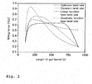
- FIG. 2 is a graph showing rifling force of each twist rate.
- FIG. 3 is a graph showing the relation between gun barrel pressure and speed of a projectile.
- Rifling is a depressed and prominent part processed on the inner surface of a gun barrel in order to impart a spin to a projectile, which refers to a part protruding from the inner surface of the gun barrel.
- a projectile which refers to a part protruding from the inner surface of the gun barrel.
- a rifling groove a hollow part formed by the protruding rifling.
- An action force generated between the projectile and the rifling when the projectile moves along the inner surface of the gun barrel by gun barrel pressure p(x) is referred to as rifling force R(x) and can be theorized as shown in mathematical expression 2.
- R x 4 D 2 ⁇ J p m p ⁇ dy dx ⁇ P x + d 2 ⁇ y dx 2 ⁇ v ⁇ x 2 ⁇ m p
- the rifling force may be expressed in terms of a rifling slope, mass of a projectile, action force of gun barrel pressure, speed of a projectile, mass moment of inertia of a projectile, a twist rate, and a rate of change of a twist rate. Accordingly, a curve of rifling force with respect to the length of a gun barrel is determined depending on the type of a projectile, and the rifling force may be changed by changing the twist rate, i.e., the rifling angle.
- FIG. 1 is a graph showing the shape of rifling angles with respect to the length of a gun barrel of each twist rate
- FIG. 2 is a graph showing rifling force of each twist rate
- FIG. 3 is a graph showing the relation between gun barrel pressure and speed of a projectile.
- the portion showing a steady twist rate in the curve of rifling force of FIG. 2 exactly shows characteristics of the gun barrel pressure of FIG. 3 , and thus it is understood that a locally concentrated load is generated at a certain portion of the gun barrel so as to negatively affect from the viewpoint of the lifespan of the gun barrel.
- the only thing to do is to obtain a rifling force having a smallest maximum value from numerous rifling force functions satisfying all restrictive conditions by determining a target to be minimized as "the maximum rifling force" and applying a numerical optimization technique that is already publicized.
- the rifling force R(x) is a function of a twist rate ( dy dx ) and the twist rate has a relation of mathematical expression 1 with the rifling angle ⁇
- the rifling force may be expressed as a function of rifling angle. Accordingly, the function of rifling angle, which is a variable, needs to be expanded in order to obtain a function of an optimum rifling force.
- a function most frequently used in expanding a function of variables is a polynomial function or a Fourier function.
- the polynomial function faithfully satisfies given boundary conditions, but convergence is not guaranteed although the number of terms is increased.
- the Fourier function guarantees convergence furthermore as the number of terms is increased, but it does not satisfy the boundary conditions.
- a rifling angle function is defined through function expansion which takes only the advantages of the polynomial and Fourier functions by combining the two functions, thereby minimizing the rifling force, which is an objective function. Therefore, the boundary conditions at the start and end points of the rifling angle are faithfully satisfied, and an optimum rifling angle for minimizing the rifling force can be calculated.
- rifling angle ⁇ (x) which is a parameter of the rifling force, may be calculated by expanding the rifling angle ⁇ (x) as shown below.
- x denotes a distance from a gun breech with respect to a gun barrel axis
- f(x) is equal to x multiplied by a constant parameter
- a i , b j , and c j are constants.
- mathematical expression 3 may be expressed as shown in mathematical expression 4.
- x i denotes a distance from the gun breech to the start point of rifling
- x e denotes a distance from the gun breech to the end point of rifling
- Constant a i of the polynomial is expressed in terms of constants b j and c j of a Fourier function through restrictive conditions, and constant a i of the polynomial is obtained by calculating the Fourier function through an optimization program.
- Constant a i of the polynomial may be expressed as constants b j and c j of a Fourier function by applying both of two terms b j cos j ⁇ x x e - x i and c j sin j ⁇ x x e - x i constructing the Fourier function. Since any one of the terms may be removed without making a problem due to the characteristics of a harmonic function, the mathematical expression is expanded using only the first term for convenience sake.
- constant a i of the polynomial may be expressed in terms of constants b j of a Fourier function through restrictive conditions shown below.
- x i denotes a distance to the start point of rifling
- x e denotes a distance to the end point of rifling
- ⁇ e denotes a rifling angle at the end point of rifling.
- the first restrictive condition represents a rifling angle at the end of the gun muzzle, which is used to restrict motions after a projectile departs from the gun barrel
- the second and third restrictive conditions are setting changes of the rifling angle to '0' in order to minimize changes of rifling force at the start and end points
- the final restrictive condition is a term related to a band of a projectile, which is a condition for maintaining the function of the projectile band.
- the final restrictive condition is a condition for confirming whether or not the rifling angle calculated through the optimization process is satisfied, which is not used in the process of deriving connectivity between constants of the polynomial function and constants of the Fourier function. Accordingly, if the polynomial constants are theorized by applying three restrictive conditions from the first, it is expressed as shown in mathematical expression 5.
- a difference between rifling angle ⁇ (x e ) at the end point of rifling and rifling angle ⁇ (x i ) at the start point of rifling may be less than 5.5, and thus the projectile band may be protected.
- This may be theeorized as shown in mathematical expression 6.
- ⁇ ⁇ a a e - a i ⁇ 5.5 ⁇ °
- ⁇ e is a rifling angle at the end point of rifling
- ⁇ i is a rifling angle at the start point of rifling
- rifling may be formed inside a gun barrel based on the rifling angle calculated by the mathematical expressions described above.
- the maximum value of the rifling force applied to a fired projectile is reduced in the gun barrel where the rifling is formed like this, and thus damages on the projectile and inside of the gun barrel may be prevented.
- the gun barrel may be used for a further extended period of time, and flight performance of the projectile may be reliably guaranteed.
- the projectile band since the projectile band is protected, the projectile may normally fly.
- the present invention may be applied to a variety of gun barrels used for firing projectiles. Particularly, it is advantageous to apply the present invention to design and manufacture gun barrels that should faithfully satisfy restrictive conditions.
- the rifling angle calculating method employed in the method for forming the rifling of a gun barrel according to the present invention expands a rifling angle by combining a Fourier function and a polynomial function to take only the advantages of the two functions, and thus boundary conditions at the start and end points of the rifling angle may be faithfully satisfied, and an optimum rifling angle for minimizing the maximum rifling force may be calculated.
Landscapes
- Engineering & Computer Science (AREA)
- General Engineering & Computer Science (AREA)
- Organic Low-Molecular-Weight Compounds And Preparation Thereof (AREA)
- Ropes Or Cables (AREA)
Description
- The present invention relates to a method for forming the rifling of a gun barrel comprising a step of calculating the rifling angle according to a rifling angle calculating method, and more specifically, to a method for forming the rifling of a gun barrel comprising a step of calculating the rifling angle according to a rifling angle calculating method capable of minimizing the maximum value of rifling force generated when a gun is fired, by expanding the rifling angle into a function of length of gun barrel.
- A rifling angle α is an angle expressing a shape y of rifling along the direction of length x of a gun barrel, which can be expressed in mathematical expression 1 shown below.

- Conventionally, rifling is designed by stabilizing twist rate

- A method of expanding the rifling angle into a Fourier function has been proposed in order to improve the problems.
Document EP 0 437 675 A2 discloses for instance a rifling angle expanded into a sum of cosines. However, if the rifling angle is expanded only into the Fourier function, convergence is guaranteed as the number of terms is increased, but it is disadvantageous in that boundary conditions cannot be satisfied. That is, since the convergence is processed only within the boundary conditions, there is no way to process the boundary conditions at the start and end points of the rifling angle, and thus the boundary conditions are processed only randomly. - If the rifling angle is expanded into a polynomial function, it is advantageous in that given boundary conditions may be faithfully satisfied, but the convergence is not guaranteed although the number of terms is increased. Document
GB 2 156 055 A - Accordingly, the present invention has been made in view of the above-mentioned problems occurring in the prior art, and it is an object of the present invention to provide a method for forming the rifling of a gun barrel comprising a step of calculating the rifling angle according to a rifling angle calculating method capable of minimizing the maximum value of rifling force generated when a gun is fired.
- Technical problems to be solved in the present invention are not limited to the technical problems described above, and unmentioned other technical problems will become apparent to those skilled in the art from the following descriptions.
- To accomplish the above objects, according to an aspect of the present invention, there is provided a method for forming the rifling of a gun barrel comprising a step of calculating the rifling angle according to a rifling angle calculating method, in which rifling angle α(x), i.e., a parameter of rifling force, is calculated by expanding the rifling angle into a mathematical expression shown below in order to minimize a maximum value of the rifling force generated between a projectile and rifling when the projectile moves along an inner surface of a gun barrel by gun barrel pressure.

- Here, x denotes a distance from a gun breech with respect to a gun barrel axis, f(x) is equal to x multiplied by a constant parameter, and ai, bj, and cj are constants.
- At this point, f(x) may be

- In addition, among the calculated rifling angles, a difference between rifling angle α(xe) at the end point of the rifling and rifling angle α(xi) at the start point of the rifling may be less than 5.5.
- Meanwhile, the rifling angle may be formed in the gun barrel according to the rifling forming method described above.
-
FIG. 1 is a graph showing the shape of rifling angles with respect to the length of a gun barrel of each twist rate. -
FIG. 2 is a graph showing rifling force of each twist rate. -
FIG. 3 is a graph showing the relation between gun barrel pressure and speed of a projectile. - Rifling is a depressed and prominent part processed on the inner surface of a gun barrel in order to impart a spin to a projectile, which refers to a part protruding from the inner surface of the gun barrel. At this point, a hollow part formed by the protruding rifling is referred to as a rifling groove. An action force generated between the projectile and the rifling when the projectile moves along the inner surface of the gun barrel by gun barrel pressure p(x) is referred to as rifling force R(x) and can be theorized as shown in mathematical expression 2.

- Here, P(x) denotes action force generated by gun barrel pressure p(x), which is expressed as


- Like this, the rifling force may be expressed in terms of a rifling slope, mass of a projectile, action force of gun barrel pressure, speed of a projectile, mass moment of inertia of a projectile, a twist rate, and a rate of change of a twist rate. Accordingly, a curve of rifling force with respect to the length of a gun barrel is determined depending on the type of a projectile, and the rifling force may be changed by changing the twist rate, i.e., the rifling angle.
-
FIG. 1 is a graph showing the shape of rifling angles with respect to the length of a gun barrel of each twist rate,FIG. 2 is a graph showing rifling force of each twist rate, andFIG. 3 is a graph showing the relation between gun barrel pressure and speed of a projectile. The portion showing a steady twist rate in the curve of rifling force ofFIG. 2 exactly shows characteristics of the gun barrel pressure ofFIG. 3 , and thus it is understood that a locally concentrated load is generated at a certain portion of the gun barrel so as to negatively affect from the viewpoint of the lifespan of the gun barrel. In the case of a linear function type, a considerably magnificent rifling force is generated at the time point when a projectile departs from the gun barrel, and thus it may be determined that flight of the projectile will be affected thereby. In the case of a quadratic function type, it is confirmed that a further satisfactory result appears compared to the two cases described above. Like this, it may be expected that the maximum rifling force can be minimized by changing the twist rate, i.e., a shape of the rifling angle. - That is, the only thing to do is to obtain a rifling force having a smallest maximum value from numerous rifling force functions satisfying all restrictive conditions by determining a target to be minimized as "the maximum rifling force" and applying a numerical optimization technique that is already publicized. Since the rifling force R(x) is a function of a twist rate (

- Generally, a function most frequently used in expanding a function of variables is a polynomial function or a Fourier function. The polynomial function faithfully satisfies given boundary conditions, but convergence is not guaranteed although the number of terms is increased. On the contrary, the Fourier function guarantees convergence furthermore as the number of terms is increased, but it does not satisfy the boundary conditions. In the present invention, in expanding a rifling angle as a function, a rifling angle function is defined through function expansion which takes only the advantages of the polynomial and Fourier functions by combining the two functions, thereby minimizing the rifling force, which is an objective function. Therefore, the boundary conditions at the start and end points of the rifling angle are faithfully satisfied, and an optimum rifling angle for minimizing the rifling force can be calculated.
- Function expansion which takes only the advantages of the polynomial and Fourier functions by combining the two functions is performed in expanding the rifling angle, and the function combining the two functions is as shown in mathematical expression 3. In other words, in order to minimize the maximum value of the rifling force generated between a projectile and rifling when the projectile moves along the inner surface of the gun barrel by gun barrel pressure, rifling angle α(x), which is a parameter of the rifling force, may be calculated by expanding the rifling angle α(x) as shown below.

- Here, x denotes a distance from a gun breech with respect to a gun barrel axis, f(x) is equal to x multiplied by a constant parameter, and ai, bj, and cj are constants.
- At this point, if f(x) is
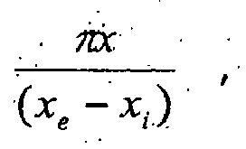

- Here, xi denotes a distance from the gun breech to the start point of rifling, and xe denotes a distance from the gun breech to the end point of rifling.
- Constant ai of the polynomial is expressed in terms of constants bj and cj of a Fourier function through restrictive conditions, and constant ai of the polynomial is obtained by calculating the Fourier function through an optimization program. Constant ai of the polynomial may be expressed as constants bj and cj of a Fourier function by applying both of two terms


- Accordingly, constant ai of the polynomial may be expressed in terms of constants bj of a Fourier function through restrictive conditions shown below.


- Here, xi denotes a distance to the start point of rifling, xe denotes a distance to the end point of rifling, and α e denotes a rifling angle at the end point of rifling. The first restrictive condition represents a rifling angle at the end of the gun muzzle, which is used to restrict motions after a projectile departs from the gun barrel, and the second and third restrictive conditions are setting changes of the rifling angle to '0' in order to minimize changes of rifling force at the start and end points. The final restrictive condition is a term related to a band of a projectile, which is a condition for maintaining the function of the projectile band. That is, it is a condition for preventing loss of function caused by the change of plasticity resulting from the contact of the band attached on the outer surface of the projectile with the rifling when the projectile proceeds through the inner surface of the gun barrel. The final restrictive condition is a condition for confirming whether or not the rifling angle calculated through the optimization process is satisfied, which is not used in the process of deriving connectivity between constants of the polynomial function and constants of the Fourier function. Accordingly, if the polynomial constants are theorized by applying three restrictive conditions from the first, it is expressed as shown in
mathematical expression 5.
- If constant ai of the polynomial is converted into constant bj of the Fourier function and each constant bj of the Fourier function is obtained through a numerical optimization technique, the maximum rifling force may be minimized, and a rifling angle faithfully satisfying the restrictive conditions may be calculated.
- Examples of constant terms of the polynomial and Fourier functions calculated as a result of the optimization performed on a gun system having rifling through the present invention are as shown below. Only ten constant terms of the Fourier function are used.
- If constant terms of an optimized polynomial function are as shown in Table 1, constant terms of the optimized Fourier function are as shown in Table 2.
[Table 1] a0 a1 a2 6.1241 -0.4491 -0.0032 [Table 2] b1 b2 b3 b4 b5 -2.1420 -0.0116 0.0174 -0.0339 0.0366 b6 b7 b8 b9 b10 0.0026 0.0080 0.0029 -0.0004 -0.0015 - Curves of rifling angle and rifling force finally calculated using the tables are shown in
FIGs. 1 and2 (displayed as an optimum twist rate (solid line)). - Observing the figures, it may be confirmed that boundary condition at the start and end points of the rifling angle are faithfully satisfied and the maximum rifling force is reduced compared with those of the other methods.
- Meanwhile, among the calculated rifling angles, a difference between rifling angle α(xe) at the end point of rifling and rifling angle α(xi) at the start point of rifling may be less than 5.5, and thus the projectile band may be protected. This may be theeorized as shown in
mathematical expression 6.
- Here, αe is a rifling angle at the end point of rifling, and αi is a rifling angle at the start point of rifling.
- Meanwhile, rifling may be formed inside a gun barrel based on the rifling angle calculated by the mathematical expressions described above. The maximum value of the rifling force applied to a fired projectile is reduced in the gun barrel where the rifling is formed like this, and thus damages on the projectile and inside of the gun barrel may be prevented. As a result, the gun barrel may be used for a further extended period of time, and flight performance of the projectile may be reliably guaranteed. Furthermore, since the projectile band is protected, the projectile may normally fly.
- The present invention may be applied to a variety of gun barrels used for firing projectiles. Particularly, it is advantageous to apply the present invention to design and manufacture gun barrels that should faithfully satisfy restrictive conditions.
- As described above, the rifling angle calculating method employed in the method for forming the rifling of a gun barrel according to the present invention expands a rifling angle by combining a Fourier function and a polynomial function to take only the advantages of the two functions, and thus boundary conditions at the start and end points of the rifling angle may be faithfully satisfied, and an optimum rifling angle for minimizing the maximum rifling force may be calculated.
Claims (3)
- A method for forming the rifling of a gun barrel comprising a step of calculating the rifling angle according to a rifling angle calculating method, in which rifling angle α(x) is calculated by expanding the rifling angle into a mathematical expression in order to minimize a maximum value of the rifling force generated between a projectile and rifling when the projectile moves along an inner surface of a gun barrel by gun barrel pressure, characterized in that the mathematical expression of the function expansion combines a polynomial function and a Fourier function and is

- The method according to claim 1, wherein f (x) is

- A gun barrel formed with rifling having a rifling angle formed according to claim 1 or 2.
Applications Claiming Priority (1)
| Application Number | Priority Date | Filing Date | Title |
|---|---|---|---|
| KR1020110009566A KR20120088306A (en) | 2011-01-31 | 2011-01-31 | Rifling angle calculating method |
Publications (3)
| Publication Number | Publication Date |
|---|---|
| EP2482022A2 EP2482022A2 (en) | 2012-08-01 |
| EP2482022A3 EP2482022A3 (en) | 2014-03-12 |
| EP2482022B1 true EP2482022B1 (en) | 2015-05-20 |
Family
ID=45592182
Family Applications (1)
| Application Number | Title | Priority Date | Filing Date |
|---|---|---|---|
| EP20120152313 Revoked EP2482022B1 (en) | 2011-01-31 | 2012-01-24 | Method for forming the rifling of a gun barrel based on a rifling angle calculating method |
Country Status (3)
| Country | Link |
|---|---|
| US (1) | US8635797B2 (en) |
| EP (1) | EP2482022B1 (en) |
| KR (1) | KR20120088306A (en) |
Families Citing this family (6)
| Publication number | Priority date | Publication date | Assignee | Title |
|---|---|---|---|---|
| US9212860B2 (en) | 2013-02-28 | 2015-12-15 | Daniel Kunau | Firearm rifling |
| US20160209146A1 (en) * | 2015-01-21 | 2016-07-21 | Lawrence Wilson Smith | Shotgun Tube Having Gain Twist Rifling |
| CN107515983A (en) * | 2017-08-18 | 2017-12-26 | 中国人民解放军军械工程学院 | Design method of self-tight barrel for guns based on the fourth strength theory |
| CN107314705B (en) * | 2017-08-18 | 2019-10-01 | 中国人民解放军陆军工程大学 | Firearm single barrel tube design method based on fourth strength theory |
| KR102076826B1 (en) | 2018-11-09 | 2020-02-12 | 국방과학연구소 | Method for designing rifling rate to increase lifespan of the gun barrel |
| US10883785B1 (en) * | 2019-09-13 | 2021-01-05 | U.S. Government As Represented By The Secretary Of The Army | Gun barrel equipped with alternating variable pitch rifling |
Citations (3)
| Publication number | Priority date | Publication date | Assignee | Title |
|---|---|---|---|---|
| DE3341820A1 (en) | 1983-11-19 | 1985-05-30 | Mauser-Werke Oberndorf Gmbh, 7238 Oberndorf | Method and device for determining the angle of twist of weapon tubes |
| GB2156055A (en) | 1984-03-13 | 1985-10-02 | Mauser Werke Oberndorf | Gun barrel with a rifling/land profile |
| EP0437675A2 (en) | 1990-01-17 | 1991-07-24 | Rheinmetall Industrie GmbH | Grooves for a gun barrel |
Family Cites Families (4)
| Publication number | Priority date | Publication date | Assignee | Title |
|---|---|---|---|---|
| DE4200171C2 (en) * | 1992-01-07 | 2001-07-26 | Rheinmetall W & M Gmbh | Gun barrel |
| DE19729294A1 (en) * | 1997-07-09 | 1999-01-14 | Rheinmetall W & M Gmbh | Gun barrel |
| US6739083B2 (en) * | 2001-09-12 | 2004-05-25 | Bore Science Technologies, L.L.C. | Runout correction rifle barrel |
| US7802394B1 (en) * | 2007-09-07 | 2010-09-28 | David John Bartoli | Rifle barrel and method of determining rifling twist for very long range accuracy |
-
2011
- 2011-01-31 KR KR1020110009566A patent/KR20120088306A/en not_active Ceased
-
2012
- 2012-01-24 EP EP20120152313 patent/EP2482022B1/en not_active Revoked
- 2012-01-26 US US13/358,796 patent/US8635797B2/en not_active Expired - Fee Related
Patent Citations (4)
| Publication number | Priority date | Publication date | Assignee | Title |
|---|---|---|---|---|
| DE3341820A1 (en) | 1983-11-19 | 1985-05-30 | Mauser-Werke Oberndorf Gmbh, 7238 Oberndorf | Method and device for determining the angle of twist of weapon tubes |
| GB2156055A (en) | 1984-03-13 | 1985-10-02 | Mauser Werke Oberndorf | Gun barrel with a rifling/land profile |
| DE3409073C2 (en) | 1984-03-13 | 1988-06-01 | Mauser-Werke Oberndorf Gmbh, 7238 Oberndorf, De | |
| EP0437675A2 (en) | 1990-01-17 | 1991-07-24 | Rheinmetall Industrie GmbH | Grooves for a gun barrel |
Non-Patent Citations (4)
| Title |
|---|
| "Fourierreihe", WIKIPEDIA, 8 February 2016 (2016-02-08), pages 1 - 8, XP055274865 |
| "Ganzrationale Funktion", WIKIPEDIA, 9 February 2016 (2016-02-09), pages 1 - 10, XP055274862 |
| ANONYMOUS: "Polynom", WIKIPEDIA, 8 February 2016 (2016-02-08), pages 1 - 6, XP055274859 |
| RHEINMETALL: "Waffentechnisches Taschenbuch", 1995, article "Die Beanspruchung der Geschosse beim Abschuss", pages: 523 - 531, XP055274864 |
Also Published As
| Publication number | Publication date |
|---|---|
| KR20120088306A (en) | 2012-08-08 |
| EP2482022A3 (en) | 2014-03-12 |
| US20120192475A1 (en) | 2012-08-02 |
| EP2482022A2 (en) | 2012-08-01 |
| US8635797B2 (en) | 2014-01-28 |
Similar Documents
| Publication | Publication Date | Title |
|---|---|---|
| EP2482022A2 (en) | Rifling angle calculating method | |
| US10663271B2 (en) | Predictably fragmenting projectiles having internally-arranged geometric features | |
| US20140373746A1 (en) | High volume multiple component projectile assembly | |
| US2838000A (en) | Projectile and method of making the same | |
| US20090123286A1 (en) | Assembly of a fan blade and of its damper, fan blade damper and method for calibrating the damper | |
| US10113846B2 (en) | Systems and methods for reducing munition sensitivity | |
| US20220381542A1 (en) | Solid bullet, intermediate product for manufacturing a solid bullet, and method for producing a solid bullet | |
| US20170167837A1 (en) | Monolithic bullet projectile for rifle firearms and method of making same | |
| US9446440B2 (en) | Method for producing a gun barrel having barrel flutings | |
| US20150204639A1 (en) | Pellet for air guns | |
| US20130255524A1 (en) | Projectile Casing for an Explosive Projectile and Method for Handling a Projectile Casing | |
| US9017176B2 (en) | Method and rolling die for producing a screw with a variable thread pitch | |
| CN1914479A (en) | Lead free monobloc expansion projectile and manufacturing process | |
| US20130004110A1 (en) | Bearing ring | |
| JP2022536715A (en) | Bullets (projectiles), in particular modified and/or partial fragmentation bullets, and methods of manufacturing bullets (projectiles) | |
| EP3272435A1 (en) | H-shaped steel production method and h-shaped steel product | |
| US20180030927A1 (en) | Propellant grain for a solid rocket motor | |
| KR20230150369A (en) | Metal practice cartridge bullets | |
| KR101916598B1 (en) | Fragmentation liner inducing formation of uniform size and method of manufacturing the same | |
| US4437251A (en) | Full gain twist ratchet rifling | |
| US10124400B2 (en) | Casting die | |
| EP3751228A1 (en) | Projectile, method of manufacturing a projectile and ammunition | |
| KR20230149841A (en) | Modified bullets for police and authority ammunition | |
| RU2556399C2 (en) | Small arms cartridge bullet | |
| KR102076826B1 (en) | Method for designing rifling rate to increase lifespan of the gun barrel |
Legal Events
| Date | Code | Title | Description |
|---|---|---|---|
| PUAI | Public reference made under article 153(3) epc to a published international application that has entered the european phase |
Free format text: ORIGINAL CODE: 0009012 |
|
| 17P | Request for examination filed |
Effective date: 20120124 |
|
| AK | Designated contracting states |
Kind code of ref document: A2 Designated state(s): AL AT BE BG CH CY CZ DE DK EE ES FI FR GB GR HR HU IE IS IT LI LT LU LV MC MK MT NL NO PL PT RO RS SE SI SK SM TR |
|
| AX | Request for extension of the european patent |
Extension state: BA ME |
|
| PUAL | Search report despatched |
Free format text: ORIGINAL CODE: 0009013 |
|
| AK | Designated contracting states |
Kind code of ref document: A3 Designated state(s): AL AT BE BG CH CY CZ DE DK EE ES FI FR GB GR HR HU IE IS IT LI LT LU LV MC MK MT NL NO PL PT RO RS SE SI SK SM TR |
|
| AX | Request for extension of the european patent |
Extension state: BA ME |
|
| RIC1 | Information provided on ipc code assigned before grant |
Ipc: F41A 21/18 20060101AFI20140203BHEP |
|
| RBV | Designated contracting states (corrected) |
Designated state(s): AL AT BE BG CH CY CZ DE DK EE ES FI FR GB GR HR HU IE IS IT LI LT LU LV MC MK MT NL NO PL PT RO RS SE SI SK SM TR |
|
| GRAP | Despatch of communication of intention to grant a patent |
Free format text: ORIGINAL CODE: EPIDOSNIGR1 |
|
| INTG | Intention to grant announced |
Effective date: 20141209 |
|
| GRAS | Grant fee paid |
Free format text: ORIGINAL CODE: EPIDOSNIGR3 |
|
| GRAA | (expected) grant |
Free format text: ORIGINAL CODE: 0009210 |
|
| AK | Designated contracting states |
Kind code of ref document: B1 Designated state(s): AL AT BE BG CH CY CZ DE DK EE ES FI FR GB GR HR HU IE IS IT LI LT LU LV MC MK MT NL NO PL PT RO RS SE SI SK SM TR |
|
| REG | Reference to a national code |
Ref country code: GB Ref legal event code: FG4D |
|
| REG | Reference to a national code |
Ref country code: CH Ref legal event code: EP |
|
| REG | Reference to a national code |
Ref country code: AT Ref legal event code: REF Ref document number: 727944 Country of ref document: AT Kind code of ref document: T Effective date: 20150615 |
|
| REG | Reference to a national code |
Ref country code: IE Ref legal event code: FG4D |
|
| REG | Reference to a national code |
Ref country code: DE Ref legal event code: R096 Ref document number: 602012007351 Country of ref document: DE |
|
| REG | Reference to a national code |
Ref country code: AT Ref legal event code: MK05 Ref document number: 727944 Country of ref document: AT Kind code of ref document: T Effective date: 20150520 |
|
| REG | Reference to a national code |
Ref country code: LT Ref legal event code: MG4D |
|
| REG | Reference to a national code |
Ref country code: NL Ref legal event code: MP Effective date: 20150520 |
|
| PG25 | Lapsed in a contracting state [announced via postgrant information from national office to epo] |
Ref country code: ES Free format text: LAPSE BECAUSE OF FAILURE TO SUBMIT A TRANSLATION OF THE DESCRIPTION OR TO PAY THE FEE WITHIN THE PRESCRIBED TIME-LIMIT Effective date: 20150520 Ref country code: NO Free format text: LAPSE BECAUSE OF FAILURE TO SUBMIT A TRANSLATION OF THE DESCRIPTION OR TO PAY THE FEE WITHIN THE PRESCRIBED TIME-LIMIT Effective date: 20150820 Ref country code: LT Free format text: LAPSE BECAUSE OF FAILURE TO SUBMIT A TRANSLATION OF THE DESCRIPTION OR TO PAY THE FEE WITHIN THE PRESCRIBED TIME-LIMIT Effective date: 20150520 Ref country code: HR Free format text: LAPSE BECAUSE OF FAILURE TO SUBMIT A TRANSLATION OF THE DESCRIPTION OR TO PAY THE FEE WITHIN THE PRESCRIBED TIME-LIMIT Effective date: 20150520 Ref country code: PT Free format text: LAPSE BECAUSE OF FAILURE TO SUBMIT A TRANSLATION OF THE DESCRIPTION OR TO PAY THE FEE WITHIN THE PRESCRIBED TIME-LIMIT Effective date: 20150921 Ref country code: FI Free format text: LAPSE BECAUSE OF FAILURE TO SUBMIT A TRANSLATION OF THE DESCRIPTION OR TO PAY THE FEE WITHIN THE PRESCRIBED TIME-LIMIT Effective date: 20150520 |
|
| PG25 | Lapsed in a contracting state [announced via postgrant information from national office to epo] |
Ref country code: LV Free format text: LAPSE BECAUSE OF FAILURE TO SUBMIT A TRANSLATION OF THE DESCRIPTION OR TO PAY THE FEE WITHIN THE PRESCRIBED TIME-LIMIT Effective date: 20150520 Ref country code: BG Free format text: LAPSE BECAUSE OF FAILURE TO SUBMIT A TRANSLATION OF THE DESCRIPTION OR TO PAY THE FEE WITHIN THE PRESCRIBED TIME-LIMIT Effective date: 20150820 Ref country code: AT Free format text: LAPSE BECAUSE OF FAILURE TO SUBMIT A TRANSLATION OF THE DESCRIPTION OR TO PAY THE FEE WITHIN THE PRESCRIBED TIME-LIMIT Effective date: 20150520 Ref country code: RS Free format text: LAPSE BECAUSE OF FAILURE TO SUBMIT A TRANSLATION OF THE DESCRIPTION OR TO PAY THE FEE WITHIN THE PRESCRIBED TIME-LIMIT Effective date: 20150520 Ref country code: IS Free format text: LAPSE BECAUSE OF FAILURE TO SUBMIT A TRANSLATION OF THE DESCRIPTION OR TO PAY THE FEE WITHIN THE PRESCRIBED TIME-LIMIT Effective date: 20150920 Ref country code: GR Free format text: LAPSE BECAUSE OF FAILURE TO SUBMIT A TRANSLATION OF THE DESCRIPTION OR TO PAY THE FEE WITHIN THE PRESCRIBED TIME-LIMIT Effective date: 20150821 |
|
| PG25 | Lapsed in a contracting state [announced via postgrant information from national office to epo] |
Ref country code: DK Free format text: LAPSE BECAUSE OF FAILURE TO SUBMIT A TRANSLATION OF THE DESCRIPTION OR TO PAY THE FEE WITHIN THE PRESCRIBED TIME-LIMIT Effective date: 20150520 Ref country code: EE Free format text: LAPSE BECAUSE OF FAILURE TO SUBMIT A TRANSLATION OF THE DESCRIPTION OR TO PAY THE FEE WITHIN THE PRESCRIBED TIME-LIMIT Effective date: 20150520 |
|
| REG | Reference to a national code |
Ref country code: DE Ref legal event code: R026 Ref document number: 602012007351 Country of ref document: DE |
|
| PLBI | Opposition filed |
Free format text: ORIGINAL CODE: 0009260 |
|
| PG25 | Lapsed in a contracting state [announced via postgrant information from national office to epo] |
Ref country code: RO Free format text: LAPSE BECAUSE OF NON-PAYMENT OF DUE FEES Effective date: 20150520 Ref country code: PL Free format text: LAPSE BECAUSE OF FAILURE TO SUBMIT A TRANSLATION OF THE DESCRIPTION OR TO PAY THE FEE WITHIN THE PRESCRIBED TIME-LIMIT Effective date: 20150520 Ref country code: SK Free format text: LAPSE BECAUSE OF FAILURE TO SUBMIT A TRANSLATION OF THE DESCRIPTION OR TO PAY THE FEE WITHIN THE PRESCRIBED TIME-LIMIT Effective date: 20150520 Ref country code: CZ Free format text: LAPSE BECAUSE OF FAILURE TO SUBMIT A TRANSLATION OF THE DESCRIPTION OR TO PAY THE FEE WITHIN THE PRESCRIBED TIME-LIMIT Effective date: 20150520 |
|
| 26 | Opposition filed |
Opponent name: RHEINMETALL WAFFE MUNITION GMBH Effective date: 20160218 |
|
| PLAX | Notice of opposition and request to file observation + time limit sent |
Free format text: ORIGINAL CODE: EPIDOSNOBS2 |
|
| PG25 | Lapsed in a contracting state [announced via postgrant information from national office to epo] |
Ref country code: IT Free format text: LAPSE BECAUSE OF FAILURE TO SUBMIT A TRANSLATION OF THE DESCRIPTION OR TO PAY THE FEE WITHIN THE PRESCRIBED TIME-LIMIT Effective date: 20150520 |
|
| PGFP | Annual fee paid to national office [announced via postgrant information from national office to epo] |
Ref country code: DE Payment date: 20160108 Year of fee payment: 5 |
|
| PG25 | Lapsed in a contracting state [announced via postgrant information from national office to epo] |
Ref country code: BE Free format text: LAPSE BECAUSE OF NON-PAYMENT OF DUE FEES Effective date: 20160131 Ref country code: SI Free format text: LAPSE BECAUSE OF FAILURE TO SUBMIT A TRANSLATION OF THE DESCRIPTION OR TO PAY THE FEE WITHIN THE PRESCRIBED TIME-LIMIT Effective date: 20150520 |
|
| PGFP | Annual fee paid to national office [announced via postgrant information from national office to epo] |
Ref country code: GB Payment date: 20160118 Year of fee payment: 5 |
|
| PG25 | Lapsed in a contracting state [announced via postgrant information from national office to epo] |
Ref country code: LU Free format text: LAPSE BECAUSE OF FAILURE TO SUBMIT A TRANSLATION OF THE DESCRIPTION OR TO PAY THE FEE WITHIN THE PRESCRIBED TIME-LIMIT Effective date: 20160124 Ref country code: BE Free format text: LAPSE BECAUSE OF FAILURE TO SUBMIT A TRANSLATION OF THE DESCRIPTION OR TO PAY THE FEE WITHIN THE PRESCRIBED TIME-LIMIT Effective date: 20150520 |
|
| REG | Reference to a national code |
Ref country code: CH Ref legal event code: PL |
|
| PG25 | Lapsed in a contracting state [announced via postgrant information from national office to epo] |
Ref country code: MC Free format text: LAPSE BECAUSE OF FAILURE TO SUBMIT A TRANSLATION OF THE DESCRIPTION OR TO PAY THE FEE WITHIN THE PRESCRIBED TIME-LIMIT Effective date: 20150520 |
|
| REG | Reference to a national code |
Ref country code: FR Ref legal event code: ST Effective date: 20160930 |
|
| PG25 | Lapsed in a contracting state [announced via postgrant information from national office to epo] |
Ref country code: LI Free format text: LAPSE BECAUSE OF NON-PAYMENT OF DUE FEES Effective date: 20160131 Ref country code: CH Free format text: LAPSE BECAUSE OF NON-PAYMENT OF DUE FEES Effective date: 20160131 |
|
| REG | Reference to a national code |
Ref country code: IE Ref legal event code: MM4A |
|
| RDAF | Communication despatched that patent is revoked |
Free format text: ORIGINAL CODE: EPIDOSNREV1 |
|
| STAA | Information on the status of an ep patent application or granted ep patent |
Free format text: STATUS: THE PATENT HAS BEEN GRANTED |
|
| PG25 | Lapsed in a contracting state [announced via postgrant information from national office to epo] |
Ref country code: FR Free format text: LAPSE BECAUSE OF NON-PAYMENT OF DUE FEES Effective date: 20160201 |
|
| REG | Reference to a national code |
Ref country code: DE Ref legal event code: R064 Ref document number: 602012007351 Country of ref document: DE Ref country code: DE Ref legal event code: R103 Ref document number: 602012007351 Country of ref document: DE |
|
| PG25 | Lapsed in a contracting state [announced via postgrant information from national office to epo] |
Ref country code: IE Free format text: LAPSE BECAUSE OF NON-PAYMENT OF DUE FEES Effective date: 20160124 |
|
| RDAG | Patent revoked |
Free format text: ORIGINAL CODE: 0009271 |
|
| 27W | Patent revoked |
Effective date: 20161210 |
|
| GBPR | Gb: patent revoked under art. 102 of the ep convention designating the uk as contracting state |
Effective date: 20161210 |
|
| PG25 | Lapsed in a contracting state [announced via postgrant information from national office to epo] |
Ref country code: SE Free format text: LAPSE BECAUSE OF FAILURE TO SUBMIT A TRANSLATION OF THE DESCRIPTION OR TO PAY THE FEE WITHIN THE PRESCRIBED TIME-LIMIT Effective date: 20150520 Ref country code: NL Free format text: LAPSE BECAUSE OF FAILURE TO SUBMIT A TRANSLATION OF THE DESCRIPTION OR TO PAY THE FEE WITHIN THE PRESCRIBED TIME-LIMIT Effective date: 20150520 |
|
| PG25 | Lapsed in a contracting state [announced via postgrant information from national office to epo] |
Ref country code: MT Free format text: LAPSE BECAUSE OF NON-PAYMENT OF DUE FEES Effective date: 20160131 |
|
| PG25 | Lapsed in a contracting state [announced via postgrant information from national office to epo] |
Ref country code: AL Free format text: LAPSE BECAUSE OF FAILURE TO SUBMIT A TRANSLATION OF THE DESCRIPTION OR TO PAY THE FEE WITHIN THE PRESCRIBED TIME-LIMIT Effective date: 20150520 |
|
| STAA | Information on the status of an ep patent application or granted ep patent |
Free format text: STATUS: PATENT REVOKED |
|
| PG25 | Lapsed in a contracting state [announced via postgrant information from national office to epo] |
Ref country code: CY Free format text: LAPSE BECAUSE OF FAILURE TO SUBMIT A TRANSLATION OF THE DESCRIPTION OR TO PAY THE FEE WITHIN THE PRESCRIBED TIME-LIMIT Effective date: 20150520 |
|
| PG25 | Lapsed in a contracting state [announced via postgrant information from national office to epo] |
Ref country code: TR Free format text: LAPSE BECAUSE OF FAILURE TO SUBMIT A TRANSLATION OF THE DESCRIPTION OR TO PAY THE FEE WITHIN THE PRESCRIBED TIME-LIMIT Effective date: 20150520 |