EP2481927A1 - Modular tower and methods of assembling same - Google Patents
Modular tower and methods of assembling same Download PDFInfo
- Publication number
- EP2481927A1 EP2481927A1 EP12151192A EP12151192A EP2481927A1 EP 2481927 A1 EP2481927 A1 EP 2481927A1 EP 12151192 A EP12151192 A EP 12151192A EP 12151192 A EP12151192 A EP 12151192A EP 2481927 A1 EP2481927 A1 EP 2481927A1
- Authority
- EP
- European Patent Office
- Prior art keywords
- tower
- section
- assembly
- panels
- flange
- Prior art date
- Legal status (The legal status is an assumption and is not a legal conclusion. Google has not performed a legal analysis and makes no representation as to the accuracy of the status listed.)
- Granted
Links
Images





Classifications
-
- E—FIXED CONSTRUCTIONS
- E04—BUILDING
- E04H—BUILDINGS OR LIKE STRUCTURES FOR PARTICULAR PURPOSES; SWIMMING OR SPLASH BATHS OR POOLS; MASTS; FENCING; TENTS OR CANOPIES, IN GENERAL
- E04H12/00—Towers; Masts or poles; Chimney stacks; Water-towers; Methods of erecting such structures
- E04H12/02—Structures made of specified materials
- E04H12/08—Structures made of specified materials of metal
- E04H12/085—Details of flanges for tubular masts
-
- E—FIXED CONSTRUCTIONS
- E04—BUILDING
- E04H—BUILDINGS OR LIKE STRUCTURES FOR PARTICULAR PURPOSES; SWIMMING OR SPLASH BATHS OR POOLS; MASTS; FENCING; TENTS OR CANOPIES, IN GENERAL
- E04H12/00—Towers; Masts or poles; Chimney stacks; Water-towers; Methods of erecting such structures
- E04H12/02—Structures made of specified materials
- E04H12/08—Structures made of specified materials of metal
-
- E—FIXED CONSTRUCTIONS
- E04—BUILDING
- E04H—BUILDINGS OR LIKE STRUCTURES FOR PARTICULAR PURPOSES; SWIMMING OR SPLASH BATHS OR POOLS; MASTS; FENCING; TENTS OR CANOPIES, IN GENERAL
- E04H12/00—Towers; Masts or poles; Chimney stacks; Water-towers; Methods of erecting such structures
-
- F—MECHANICAL ENGINEERING; LIGHTING; HEATING; WEAPONS; BLASTING
- F03—MACHINES OR ENGINES FOR LIQUIDS; WIND, SPRING, OR WEIGHT MOTORS; PRODUCING MECHANICAL POWER OR A REACTIVE PROPULSIVE THRUST, NOT OTHERWISE PROVIDED FOR
- F03D—WIND MOTORS
- F03D13/00—Assembly, mounting or commissioning of wind motors; Arrangements specially adapted for transporting wind motor components
- F03D13/20—Arrangements for mounting or supporting wind motors; Masts or towers for wind motors
-
- F—MECHANICAL ENGINEERING; LIGHTING; HEATING; WEAPONS; BLASTING
- F03—MACHINES OR ENGINES FOR LIQUIDS; WIND, SPRING, OR WEIGHT MOTORS; PRODUCING MECHANICAL POWER OR A REACTIVE PROPULSIVE THRUST, NOT OTHERWISE PROVIDED FOR
- F03D—WIND MOTORS
- F03D80/00—Details, components or accessories not provided for in groups F03D1/00 - F03D17/00
- F03D80/70—Bearing or lubricating arrangements
-
- F—MECHANICAL ENGINEERING; LIGHTING; HEATING; WEAPONS; BLASTING
- F03—MACHINES OR ENGINES FOR LIQUIDS; WIND, SPRING, OR WEIGHT MOTORS; PRODUCING MECHANICAL POWER OR A REACTIVE PROPULSIVE THRUST, NOT OTHERWISE PROVIDED FOR
- F03D—WIND MOTORS
- F03D80/00—Details, components or accessories not provided for in groups F03D1/00 - F03D17/00
- F03D80/80—Arrangement of components within nacelles or towers
- F03D80/82—Arrangement of components within nacelles or towers of electrical components
-
- F—MECHANICAL ENGINEERING; LIGHTING; HEATING; WEAPONS; BLASTING
- F03—MACHINES OR ENGINES FOR LIQUIDS; WIND, SPRING, OR WEIGHT MOTORS; PRODUCING MECHANICAL POWER OR A REACTIVE PROPULSIVE THRUST, NOT OTHERWISE PROVIDED FOR
- F03D—WIND MOTORS
- F03D9/00—Adaptations of wind motors for special use; Combinations of wind motors with apparatus driven thereby; Wind motors specially adapted for installation in particular locations
- F03D9/20—Wind motors characterised by the driven apparatus
- F03D9/25—Wind motors characterised by the driven apparatus the apparatus being an electrical generator
-
- F—MECHANICAL ENGINEERING; LIGHTING; HEATING; WEAPONS; BLASTING
- F05—INDEXING SCHEMES RELATING TO ENGINES OR PUMPS IN VARIOUS SUBCLASSES OF CLASSES F01-F04
- F05B—INDEXING SCHEME RELATING TO WIND, SPRING, WEIGHT, INERTIA OR LIKE MOTORS, TO MACHINES OR ENGINES FOR LIQUIDS COVERED BY SUBCLASSES F03B, F03D AND F03G
- F05B2240/00—Components
- F05B2240/90—Mounting on supporting structures or systems
- F05B2240/91—Mounting on supporting structures or systems on a stationary structure
- F05B2240/912—Mounting on supporting structures or systems on a stationary structure on a tower
-
- F—MECHANICAL ENGINEERING; LIGHTING; HEATING; WEAPONS; BLASTING
- F05—INDEXING SCHEMES RELATING TO ENGINES OR PUMPS IN VARIOUS SUBCLASSES OF CLASSES F01-F04
- F05B—INDEXING SCHEME RELATING TO WIND, SPRING, WEIGHT, INERTIA OR LIKE MOTORS, TO MACHINES OR ENGINES FOR LIQUIDS COVERED BY SUBCLASSES F03B, F03D AND F03G
- F05B2260/00—Function
- F05B2260/30—Retaining components in desired mutual position
-
- Y—GENERAL TAGGING OF NEW TECHNOLOGICAL DEVELOPMENTS; GENERAL TAGGING OF CROSS-SECTIONAL TECHNOLOGIES SPANNING OVER SEVERAL SECTIONS OF THE IPC; TECHNICAL SUBJECTS COVERED BY FORMER USPC CROSS-REFERENCE ART COLLECTIONS [XRACs] AND DIGESTS
- Y02—TECHNOLOGIES OR APPLICATIONS FOR MITIGATION OR ADAPTATION AGAINST CLIMATE CHANGE
- Y02E—REDUCTION OF GREENHOUSE GAS [GHG] EMISSIONS, RELATED TO ENERGY GENERATION, TRANSMISSION OR DISTRIBUTION
- Y02E10/00—Energy generation through renewable energy sources
- Y02E10/70—Wind energy
- Y02E10/72—Wind turbines with rotation axis in wind direction
-
- Y—GENERAL TAGGING OF NEW TECHNOLOGICAL DEVELOPMENTS; GENERAL TAGGING OF CROSS-SECTIONAL TECHNOLOGIES SPANNING OVER SEVERAL SECTIONS OF THE IPC; TECHNICAL SUBJECTS COVERED BY FORMER USPC CROSS-REFERENCE ART COLLECTIONS [XRACs] AND DIGESTS
- Y02—TECHNOLOGIES OR APPLICATIONS FOR MITIGATION OR ADAPTATION AGAINST CLIMATE CHANGE
- Y02E—REDUCTION OF GREENHOUSE GAS [GHG] EMISSIONS, RELATED TO ENERGY GENERATION, TRANSMISSION OR DISTRIBUTION
- Y02E10/00—Energy generation through renewable energy sources
- Y02E10/70—Wind energy
- Y02E10/728—Onshore wind turbines
Definitions
- the subject matter disclosed herein relates generally to modular towers, and more specifically, to assembling sections of a modular tower.
- Modular towers structures are often used as bases to support structures, such as wind turbine towers, mobile phone towers, and power poles. Because of their size, such towers are often constructed on site, as the towers themselves are much larger than is practically transportable. Components used with such towers are often assembled off-site. Similar to the tower itself, transportation logistics generally limit the storage size and/or weight of such components.
- Tower height is at least partially limited by the dimensions of the base of the tower. As such, a taller tower requires a correspondingly larger base to adequately support the tower structure. To enhance the overall structural integrity and to reduce on-site assembly time, it is generally desirable to assemble the components of the modular tower in as few pieces as possible. However, due to transportation limitations, the overall size of components and sections is limited. As such, the height of the tower may be limited by the size of the unitary components that can be used in light of transportation limitations.
- a tower assembly for use with a modular tower.
- the tower assembly comprises a plurality of assembly panels each comprising a pair of opposing circumferential edges, and, a plurality of connectors for use in coupling adjacent assembly panels of the plurality of assembly panels to one another, each connector of the plurality of connectors comprising an outer flange, an inner flange, and a spacer extending therebetween, the outer flange is spaced a distance from the inner flange such that a first slot and a second slot are defined between the outer and inner flanges, each of the first and the second slots is sized to receive one of the assembly panel circumferential edges therein to enable the adjacent assembly panels to be coupled to one another.
- a method for assembling a modular tower comprises providing at least one connector each including a first flange, a second flange, and a spacer extending therebetween, providing a plurality of section panels each including a first circumferential edge and a second circumferential edge, inserting the first circumferential edge of a first of the plurality of section panels into a first slot of the connector, wherein the first slot is defined between the first flange and the second flange, inserting the second circumferential edge of a second of the plurality of section panels into a second slot of the connector, wherein the second slot is defined between the first flange and the second flange, and, coupling the connector to the first and second section panels.
- a modular tower comprising at least one lower tower section comprising a plurality of section panels each comprising a pair of opposing circumferential edges, and, a plurality of connectors for use in coupling adjacent section panels of the plurality of section panels to one another, each of the connectors comprising an outer flange, an inner flange, and a spacer extending therebetween, the outer flange is spaced a distance from the inner flange such that a first slot and a second slot are defined between the outer and inner flanges, each of the first and the second slots is sized to receive one of the section panel circumferential edges therein to enable the adjacent section panels to be coupled together.
- the modular tower further comprises at least one upper tower section coupled to the lower section.
- Various of the methods and modular tower components described herein facilitate construction of a modular tower.
- the modular tower components and methods described herein enable construction of tower sections that are larger than unitary tower sections that are limited in size by transportation limitations. Using larger modular tower sections, structurally-sound towers having higher hub heights can be constructed.
- spacer elements described herein facilitate aligning adjacent section panels together during construction, and thus, increase the structural integrity of the assembled tower.
- the flanges described herein that are used to connect adjacent tower sections together facilitate reducing hoop stresses induced to the tower components.
- Fig. 1 is a schematic view of an exemplary wind turbine 100.
- wind turbine 100 is a horizontal-axis wind turbine.
- wind turbine 100 may be a vertical-axis wind turbine.
- wind turbine 100 includes a tower 102 extending from and coupled to a supporting surface 104.
- Tower 102 may be coupled to surface 104 with anchor bolts or via a foundation mounting piece (neither shown), for example.
- a nacelle 106 is coupled to tower 102, and a rotor 108 is coupled to nacelle 106.
- Rotor 108 includes a rotatable hub 110 and a plurality of rotor blades 112 coupled to hub 110.
- rotor 108 includes three rotor blades 112.
- rotor 108 may have any suitable number of rotor blades 112 that enables wind turbine 100 to function as described herein.
- Tower 102 may have any suitable height and/or construction that enables wind turbine 100 to function as described herein.
- Rotor blades 112 are spaced about hub 110 to facilitate rotating rotor 108, thereby transferring kinetic energy from wind 114 into usable mechanical energy, and subsequently, electrical energy.
- Rotor 108 and nacelle 106 are rotated about tower 102 on a yaw axis 116 to control a perspective of rotor blades 112 with respect to a direction of wind 114.
- Rotor blades 112 are mated to hub 110 by coupling a rotor blade root portion 118 to hub 110 at a plurality of load transfer regions 120.
- Load transfer regions 120 each have a hub load transfer region and a rotor blade load transfer region (both not shown in Fig. 1 ). Loads induced to rotor blades 112 are transferred to hub 110 via load transfer regions 120.
- Each rotor blade 112 also includes a rotor blade tip portion 122.
- rotor blades 112 have a length of between approximately 30 meters (m) (99 feet (ft)) and approximately 120 m (394 ft).
- rotor blades 112 may have any suitable length that enables wind turbine 100 to function as described herein.
- rotor blades 112 may have a suitable length less than 30 m or greater than 120 m.
- a pitch angle (not shown) of rotor blades 112 may be changed by a pitch assembly (not shown in Fig. 1 ). More specifically, increasing a pitch angle of rotor blade 112 decreases an amount of rotor blade surface area 126 exposed to wind 114 and, conversely, decreasing a pitch angle of rotor blade 112 increases an amount of rotor blade surface area 126 exposed to wind 114.
- the pitch angles of rotor blades 112 are adjusted about a pitch axis 128 at each rotor blade 112. In the exemplary embodiment, the pitch angles of rotor blades 112 are controlled individually.
- Fig. 2 is a partial sectional view of nacelle 106 used with wind turbine 100.
- various components of wind turbine 100 are housed in nacelle 106.
- nacelle 106 includes pitch assemblies 130.
- Each pitch assembly 130 is coupled to an associated rotor blade 112 (shown in Fig. 1 ), and modulates a pitch of an associated rotor blade 112 about pitch axis 128.
- each pitch assembly 130 includes at least one pitch drive motor 131.
- rotor 108 is rotatably coupled to an electric generator 132 positioned within nacelle 106 via a rotor shaft 134 (sometimes referred to as either a main shaft or a low speed shaft), a gearbox 136, a high speed shaft 138, and a coupling 140.
- Rotation of rotor shaft 134 rotatably drives gearbox 136 that subsequently drives high speed shaft 138.
- High speed shaft 138 rotatably drives generator 132 via coupling 140 and rotation of high speed shaft 138 facilitates production of electrical power by generator 132.
- Gearbox 136 is supported by a support 142 and generator 132 is supported by a support 144.
- gearbox 136 uses a dual path geometry to drive high speed shaft 138.
- rotor shaft 134 may be coupled directly to generator 132 via coupling 140.
- Nacelle 106 also includes a yaw drive mechanism 146 that rotates nacelle 106 and rotor 108 about yaw axis 116 to control the perspective of rotor blades 112 with respect to the direction of wind 114.
- Nacelle 106 also includes at least one meteorological mast 148 that in one embodiment, includes a wind vane and anemometer (neither shown in Fig. 2 ).
- meteorological mast 148 provides information, including wind direction and/or wind speed, to a turbine control system 150.
- Turbine control system 150 includes one or more controllers or other processors configured to execute control algorithms.
- processor includes any programmable system including systems and microcontrollers, reduced instruction set circuits (RISC), application specific integrated circuits (ASIC), programmable logic circuits (PLC), and any other circuit capable of executing the functions described herein.
- RISC reduced instruction set circuits
- ASIC application specific integrated circuits
- PLC programmable logic circuits
- SCADA Supervisory, Control and Data Acquisition
- nacelle 106 also includes forward support bearing 152 and aft support bearing 154.
- Forward support bearing 152 and aft support bearing 154 facilitate radial support and alignment of rotor shaft 134.
- Forward support bearing 152 is coupled to rotor shaft 134 near hub 110.
- Aft support bearing 154 is positioned on rotor shaft 134 near gearbox 136 and/or generator 132.
- Nacelle 106 may include any number of support bearings that enable wind turbine 100 to function as disclosed herein.
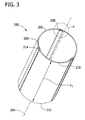
- Fig. 3 is a perspective view of an exemplary tower section 200 that may be used in assembling at least a portion of tower 102 (shown in Fig. 1 ).
- Fig. 4 is an enlarged perspective view of a portion of tower section 200 taken along area 4.
- tower section 200 is formed from a plurality of arcuate section panels 202.
- tower section 200 can be formed from a single unitary panel (not shown).
- Tower section 200 includes a center axis 204 that extends therethrough.
- tower section 200 is illustrated as being conical, tower section 200 can have any shape, including, without limitation, a cylindrical or polygonal shape, that enables tower 102 to function as described herein.
- section panels 202 can have different shapes in addition to those specifically described herein.
- section panels 202 may be formed with one or more planar surfaces.
- each section panel 202 has a first circumferential edge 206 and an opposing second circumferential edge 208.
- Section panels 202 can be made of various materials, such as carbon steel.
- at least one tower section 200 may be formed with an entry passage (not shown) that enables access to an interior cavity of tower 102 that is at least partially defined by section panels 202.
- Tower section 200 and each section panel 202 extend from a first axial edge 210 to a second axial edge 212, an axial length L 1 defined between first axial edge 210 and second axial edge 212.
- each connector 214 includes an outer flange 302, an opposite inner flange 304, and a spacer 306 that extends between flanges 302 and 304.
- outer flange 302, inner flange 304, and spacer 306 are oriented such that a first slot 308 and a second slot 310 are defmed within connector 214.
- connector 214 is fabricated from the same materials, such as carbon steel, used in fabricating section panels 202.
- connector 214 may be fabricated from a material different than section panels 202, and/or any material that enables tower 102 and tower section 200 to function as described herein.
- Connector 214 can include a joint (not shown) or any suitable connecting mechanism that enables connector 214 to couple section panels 202. Further, connector 214 may be fabricated as a unitary connector or fabricated with separate connector components. In the exemplary embodiment, each connector 214 is formed of two T-shaped portions 312 and 314. More specifically, in the exemplary embodiment, wherein section panels 202 are arcuate, T-shaped portions 312 and 314 are also arcuate to facilitate receiving section panels 202. Alternatively, T-shaped portions 312 and 314 may be angular or planar, or any other cross-sectional shape that enables tower 102 and tower section 200 to function as described herein. In the exemplary embodiment, each T-shaped portion 312 and 314 is formed with a spacer extension 316 and a flange extension 318.
- T-shaped portions 312 and 314 can be coupled together before or after section panels 202 have been inserted into slot 308 and/or 310, as described in more detail below. Any suitable fastening mechanism or technique may be used to couple spacer extensions 316 to one another.
- Connector 214 can also be formed from different configurations. For example, in one embodiment, only one T-shaped portion includes a spacer extension and the other T-shaped portion includes only a flange extension.
- connector 214 does not include spacer 306, but rather includes an outer plate and an inner plate (neither shown).
- adjacent section panels 202 contact one another or are separated by a gap, and are positioned between the outer plate and the inner plate prior to panels 202, the outer plate, and the inner plate being coupled together using any suitable coupling means, such as, bolts, welds, or rivets.
- section panels 202 can be coupled together using only the outer plate or the inner plate.
- each connector 214 includes a plurality of apertures 330 defined therein that extend therethrough.
- apertures 330 are illustrated as being oriented in circumferential rows, it should be noted that any number of apertures 330 and/or any orientation of apertures 330 that enables connector 214 to couple adjacent section panels 202 together while maintaining the strength and structural integrity of tower section 200 can be used. More specifically, in the exemplary embodiment, apertures 330 are defined in a pair of circumferential rows 332 that each extend from a first end 334 of each connector 214 to a second end 336 of each connector.
- connector T-shaped portion 314 is radially inward of T-shaped portion 312, and apertures 330 defined in T-shaped portion 314 are substantially concentrically aligned with apertures 330 defined in T-shaped portion 312.
- apertures 330 are sized and oriented to receive bolts and/or another suitable fastener therethrough that enables section panels 202 to be securely coupled to connectors 214, as described in more detail below.
- connectors 214 may not include apertures 330, but rather welds and/or rivets are used to couple section panels 202 to connectors 214 (not shown).
- apertures 330 defined in each row 332 in connector 214 are formed with same diameter D 2 and shape.
- apertures 330 in one row 332 may have a different diameter D 2 and/or shape than apertures 330 in an adjacent row 332.
- Each connector 214 is sized and oriented to couple adjacent section panels 202 together to form tower section 200.
- section panels 202 are securely coupled to connector 214.
- section panels 202 may be removably coupled to connector 214.
- section panels 202 each include a plurality of apertures 342 defined therein.
- Panel apertures 342 are sized and oriented to align with connector apertures 330.
- apertures 342 are oriented in a pair of substantially parallel rows that each extend substantially parallel to circumferential edges 206 and 208.
- first circumferential edge 206 of first section panel 202 is inserted into connector first slot 308, and second circumferential edge 208 of second section panel 202 is inserted into connector second slot 310.
- panel apertures 342 are aligned substantially concentrically with respect to apertures 330 defined in connector 214.
- a suitable fastener such as a bolt, can be inserted through apertures 330 and 342 such that the fasteners extend through flange extensions 318 and through panel circumferential edges 206 and 208 to enable section panels 202 to be securely coupled together.
- the fasteners extend in a substantially radial direction with respect to section center axis 204.
- each connector 214 has an axial length L 2 measured between ends 334 and 336 that is approximately the same as an axial length L 1 of each section panel 202. As such, in the exemplary embodiment, each connector 214 extends along entire axial length L 1 of panel circumferential edges 206 and 208. Alternatively, connector 214 only covers a portion of axial length L 1 of panel circumferential edges 206 and 208. In such an alternative embodiment, a plurality of connectors 214 may be coupled end-to-end along the full axial length L 1 of panel circumferential edges 206 and 208. Alternatively, in such an embodiment, connectors 214 may be spaced along axial length L 1 .
- Fig. 5 is a perspective cross-sectional view of a portion of alternative tower sections 400 that may be used in assembling at least a portion of tower 102 (shown in Fig. 1 ).
- tower sections 400 include a lower tower section 402 that is a conical tower section that is formed from section panels 202 as described herein with respect to tower section 200 (shown in Fig. 3 ), and an upper tower section 404 that is a unitary section.
- lower tower section 402 could be coupled to another tower section 404 that is formed of section panels 202 as opposed to a unitary tower section (not shown).
- the tower sections 200 are oriented such that the connectors 214 on the tower sections 200 are not vertically aligned with each other.
- upper tower section 404 includes a lower flange 408 that is annular and substantially planar
- lower tower section 402 includes an upper flange 406 that is annular and substantially planar
- each flange 406 and 408 is substantially circular.
- Flanges 406 and 408 each include a plurality of apertures 410 defined therein that are sized and oriented to receive a plurality of fasteners (not shown) therethrough to enable upper flange 406 to securely couple to lower flange 408.
- welds or rivets can also be used to securely couple flanges 406 and 408 together.
- Flanges 406 and/or 408 may be formed unitarily with section panels 202 and/or may be coupled to tower sections 402 and 404. Moreover, although flanges 406 and 408 are illustrated as extending radially inward from tower sections 402 and 404, in other embodiments, at least a portion of flanges 406 and/or 408 could extend radially outward from tower sections 402 and 404.
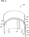
- Fig. 6 is a perspective cross-sectional view of an alternative connection between a lower tower section 402 and an upper tower section 404.
- a horizontal connector 420 is used to couple lower tower section 402 to upper tower section 404.
- horizontal connector 420 has a structure similar to connector 214. More specifically, horizontal connector 420 includes an outer flange 422, an opposite inner flange 424, and a spacer 426 that extends between flanges 422 and 424. Specifically, in the exemplary embodiment, outer flange 422, inner flange 424, and spacer 426 are oriented such that a lower slot 428 and an upper slot 430 are defined within connector 420.
- Horizontal connector 420 can include a joint (not shown) or any suitable connecting mechanism that enables connector 420 to couple lower tower section 402 to upper tower section 404.
- connector 420 is a unitary connector.
- connector 420 may be fabricated from separate connector components which may be coupled to one another, adjacent to one another, and/or spaced apart from one another.
- horizontal connector 420 includes a plurality of apertures 440 defined therein that extend therethrough, similar to apertures 330 in connector 214.
- apertures 440 are sized and oriented to receive bolts and/or another suitable fastener therethrough that enables lower tower section 402 and upper tower section 404 to be securely coupled to horizontal connector 420.
- horizontal connector 420 may not include apertures 440, but rather welds and/or rivets are used to couple lower tower section 402 and upper tower section 404 to horizontal connector 420 (not shown).
- lower tower section 402 and upper tower section 404 each include a plurality of apertures 450 defined therein. Apertures 450 are sized and oriented to align with horizontal connector apertures 440.
- an upper edge 460 of lower tower section 402 is inserted into horizontal connector lower slot 428, and a lower edge 462 of upper tower section 404 is inserted into horizontal connector upper slot 430.
- apertures 450 are aligned substantially concentrically with respect to apertures 440 defined in horizontal connector 420. Accordingly, a suitable fastener, such as a bolt, can be inserted through apertures 440 and 450 such that the fasteners extend through horizontal connector 420 and through upper edge 460 and lower edge 462 to enable lower tower section 402 and upper tower section 404 to be securely coupled together.
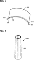
- Fig. 7 is a perspective view of an exemplary section panel 500 that may be used in assembling at least a portion of tower 102.
- section panel 500 includes an alternative section connector 502.
- Section connector 502 may be formed unitarily with section panel 500 and/or coupled to section panel 500 using any other suitable means.
- section connector 502 is substantially arcuate and includes a first flange portion 504 and a second flange portion 506.
- First flange portion 504 is sized and oriented to couple to a second flange portion 506 extending from an adjacent section panel 500.
- first flange portion 504 includes pegs 508 and second flange portion 506 includes corresponding apertures 510 that are sized and oriented to enable first flange portion 504 to couple to a second flange portion 506 extending from an adjacent section panel 500.
- flange portions 504 and 506 are substantially planar, and a second flange portion 506 extends from a first section panel 500 and overlaps a first flange portion 504 extending from a second section panel 500 when pegs 508 are inserted into apertures 510 to couple flange portions 504 and 506 together.
- first flange portion 504 and second flange portion 506 may be coupled together using any other fasteners and/or any suitable coupling means, including, but not limited to, welds or rivets.
- section connectors 502 When section panels 500 are coupled together using section connectors 502 to form a tower section, section connectors 502 form an annular and substantially planar flange (not shown) that is similar to upper circular flange 406 and lower circular flange 408 (both shown in Fig. 5 ).
- section connectors 502 are suitably flexible such that in the formed flange, one section connector 502 can flex to reduce hoop stress on the formed flange.
- section connectors 502 are generally less expensive and are generally easier to manufacture then a unitary flange.
- such connectors 502 may also be fabricated unitarily with a section panel 500.
- Fig. 8 is a perspective view of a polygonal tower section 600 that may be used in assembling at least a portion of tower 102 (shown in Fig. 1 ).
- Fig. 9 is a plan view of tower section 600.
- tower section 600 is formed from a plurality of section panels 602.
- tower section 600 is formed from four section panels 602 that are oriented such that each section panel 602 forms a quarter of tower section 600.
- tower section 600 can be formed from any number of section panels 602 that enables tower section 600 to function as described herein.
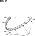
- Fig. 10 is an enlarged view of a portion of a section panel 602 coupled to an alternative tower section 606.
- section panel 602 is coupled to an upper flange portion 608, and tower section 606 is coupled to a lower flange 610.
- tower section 606 is substantially cylindrical, and lower flange 610 is annular, substantially planar, and coupled to upper flange portion 608 using fasteners 612.
- lower flange 610 and upper flange portion 608 may be coupled together using any other suitable coupling means, including, but not limited to, bolts, welds, or rivets.
- the modular tower sections described herein enable construction of larger tower sections because the section panels can be transported unassembled and independently. Moreover, section panels are generally more inexpensive and simpler to manufacture than unitary tower sections. Further, the connectors described herein improve facilitating the alignment of section panels during assembly because the spacer elements and slots secure the position of the section panels during assembly. Moreover, as compared to unitary flanges, the section connectors described herein facilitate reducing hoop stresses induced to the tower sections because the section connectors are flexible with respect to one another.
- the above described modular tower sections and methods can provide an improved modular tower.
- the tower sections include section panels and connectors, which can be transported unassembled and independently, such that larger tower sections than those practically transportable can be assembled on site. As a result, modular towers with higher hub heights can be constructed.
- the tower sections include a connector including an outer flange, an inner flange, and a spacer to define a first and second slot. The defmed slots facilitate positioning and coupling section panels to form the tower section.
- the tower sections include flexible section connectors that couple to one another to form a flange. As a result, the formed flange is better at reducing hoop stress than a unitary flange.
- Exemplary embodiments of a modular tower, modular tower sections, and methods for constructing a modular tower are described above in detail.
- the methods and systems described herein are not limited to the specific embodiments described herein, but rather, components of the systems and/or steps of the methods may be utilized independently and separately from other components and/or steps described herein.
- the methods and systems described herein may have other applications not limited to practice with wind turbines, as described herein. Rather, the methods and systems described herein can be implemented and utilized in connection with various other industries.
Landscapes
- Engineering & Computer Science (AREA)
- Chemical & Material Sciences (AREA)
- Life Sciences & Earth Sciences (AREA)
- Combustion & Propulsion (AREA)
- General Engineering & Computer Science (AREA)
- Architecture (AREA)
- Mechanical Engineering (AREA)
- Sustainable Development (AREA)
- Sustainable Energy (AREA)
- Civil Engineering (AREA)
- Structural Engineering (AREA)
- Wood Science & Technology (AREA)
- Materials Engineering (AREA)
- Power Engineering (AREA)
- Wind Motors (AREA)
- Installation Of Indoor Wiring (AREA)
Abstract
Description
- The subject matter disclosed herein relates generally to modular towers, and more specifically, to assembling sections of a modular tower.
- Modular towers structures are often used as bases to support structures, such as wind turbine towers, mobile phone towers, and power poles. Because of their size, such towers are often constructed on site, as the towers themselves are much larger than is practically transportable. Components used with such towers are often assembled off-site. Similar to the tower itself, transportation logistics generally limit the storage size and/or weight of such components.
- Tower height is at least partially limited by the dimensions of the base of the tower. As such, a taller tower requires a correspondingly larger base to adequately support the tower structure. To enhance the overall structural integrity and to reduce on-site assembly time, it is generally desirable to assemble the components of the modular tower in as few pieces as possible. However, due to transportation limitations, the overall size of components and sections is limited. As such, the height of the tower may be limited by the size of the unitary components that can be used in light of transportation limitations.
- In one aspect according to the present invention, a tower assembly for use with a modular tower is provided. The tower assembly comprises a plurality of assembly panels each comprising a pair of opposing circumferential edges, and, a plurality of connectors for use in coupling adjacent assembly panels of the plurality of assembly panels to one another, each connector of the plurality of connectors comprising an outer flange, an inner flange, and a spacer extending therebetween, the outer flange is spaced a distance from the inner flange such that a first slot and a second slot are defined between the outer and inner flanges, each of the first and the second slots is sized to receive one of the assembly panel circumferential edges therein to enable the adjacent assembly panels to be coupled to one another.
- In another aspect, a method for assembling a modular tower is provided. The method comprises providing at least one connector each including a first flange, a second flange, and a spacer extending therebetween, providing a plurality of section panels each including a first circumferential edge and a second circumferential edge, inserting the first circumferential edge of a first of the plurality of section panels into a first slot of the connector, wherein the first slot is defined between the first flange and the second flange, inserting the second circumferential edge of a second of the plurality of section panels into a second slot of the connector, wherein the second slot is defined between the first flange and the second flange, and, coupling the connector to the first and second section panels.
- In yet another aspect, a modular tower is provided. The modular tower comprises at least one lower tower section comprising a plurality of section panels each comprising a pair of opposing circumferential edges, and, a plurality of connectors for use in coupling adjacent section panels of the plurality of section panels to one another, each of the connectors comprising an outer flange, an inner flange, and a spacer extending therebetween, the outer flange is spaced a distance from the inner flange such that a first slot and a second slot are defined between the outer and inner flanges, each of the first and the second slots is sized to receive one of the section panel circumferential edges therein to enable the adjacent section panels to be coupled together. The modular tower further comprises at least one upper tower section coupled to the lower section.
- Various aspects and embodiments of the present invention will now be described in connection with the accompanying drawings, in which:
-
Fig. 1 is a schematic view of an exemplary wind turbine. -
Fig. 2 is a partial sectional view of an exemplary nacelle used with the wind turbine shown inFig. 1 . -
Fig. 3 is a perspective view of an exemplary tower section that may be used with the wind turbine shown inFig. 1 . -
Fig. 4 is an enlarged perspective view of a portion of the tower section shown inFig. 3 and taken alongarea 4. -
Fig. 5 is a perspective cross-sectional view of a portion of tower sections that may be used with the wind turbine shown inFig. 1 . -
Fig. 6 is a perspective cross-sectional view of a portion of tower sections that may be used with the wind turbine shown inFig. 1 . -
Fig. 7 is a perspective view of an exemplary section panel that may be used with the wind turbine shown inFig. 1 . -
Fig. 8 is a perspective view of an exemplary tower section that may be used with the wind turbine shown inFig. 1 . -
Fig. 9 is a plan view of the tower section shown inFig. 8 . -
Fig. 10 is an enlarged view of a portion of the tower section shown inFig. 8 . - Various of the methods and modular tower components described herein facilitate construction of a modular tower. Specifically, the modular tower components and methods described herein enable construction of tower sections that are larger than unitary tower sections that are limited in size by transportation limitations. Using larger modular tower sections, structurally-sound towers having higher hub heights can be constructed. Moreover, spacer elements described herein facilitate aligning adjacent section panels together during construction, and thus, increase the structural integrity of the assembled tower. Moreover the flanges described herein that are used to connect adjacent tower sections together, facilitate reducing hoop stresses induced to the tower components.
-
Fig. 1 is a schematic view of anexemplary wind turbine 100. In the exemplary embodiment,wind turbine 100 is a horizontal-axis wind turbine. Alternatively,wind turbine 100 may be a vertical-axis wind turbine. In the exemplary embodiment,wind turbine 100 includes atower 102 extending from and coupled to a supportingsurface 104.Tower 102 may be coupled tosurface 104 with anchor bolts or via a foundation mounting piece (neither shown), for example. Anacelle 106 is coupled totower 102, and arotor 108 is coupled tonacelle 106.Rotor 108 includes arotatable hub 110 and a plurality ofrotor blades 112 coupled tohub 110. In the exemplary embodiment,rotor 108 includes threerotor blades 112. Alternatively,rotor 108 may have any suitable number ofrotor blades 112 that enableswind turbine 100 to function as described herein. Tower 102 may have any suitable height and/or construction that enableswind turbine 100 to function as described herein. -
Rotor blades 112 are spaced abouthub 110 to facilitate rotatingrotor 108, thereby transferring kinetic energy fromwind 114 into usable mechanical energy, and subsequently, electrical energy.Rotor 108 andnacelle 106 are rotated abouttower 102 on ayaw axis 116 to control a perspective ofrotor blades 112 with respect to a direction ofwind 114.Rotor blades 112 are mated tohub 110 by coupling a rotorblade root portion 118 tohub 110 at a plurality ofload transfer regions 120.Load transfer regions 120 each have a hub load transfer region and a rotor blade load transfer region (both not shown inFig. 1 ). Loads induced torotor blades 112 are transferred tohub 110 viaload transfer regions 120. Eachrotor blade 112 also includes a rotorblade tip portion 122. - In the exemplary embodiment,
rotor blades 112 have a length of between approximately 30 meters (m) (99 feet (ft)) and approximately 120 m (394 ft). Alternatively,rotor blades 112 may have any suitable length that enableswind turbine 100 to function as described herein. For example,rotor blades 112 may have a suitable length less than 30 m or greater than 120 m. Aswind 114contacts rotor blade 112, lift forces are induced torotor blade 112 and rotation ofrotor 108 about an axis ofrotation 124 is induced as rotorblade tip portion 122 is accelerated. - A pitch angle (not shown) of
rotor blades 112, i.e., an angle that determines the perspective ofrotor blade 112 with respect to the direction ofwind 114, may be changed by a pitch assembly (not shown inFig. 1 ). More specifically, increasing a pitch angle ofrotor blade 112 decreases an amount of rotorblade surface area 126 exposed towind 114 and, conversely, decreasing a pitch angle ofrotor blade 112 increases an amount of rotorblade surface area 126 exposed towind 114. The pitch angles ofrotor blades 112 are adjusted about apitch axis 128 at eachrotor blade 112. In the exemplary embodiment, the pitch angles ofrotor blades 112 are controlled individually. -
Fig. 2 is a partial sectional view ofnacelle 106 used withwind turbine 100. In the exemplary embodiment, various components ofwind turbine 100 are housed innacelle 106. For example, in the exemplary embodiment,nacelle 106 includespitch assemblies 130. Eachpitch assembly 130 is coupled to an associated rotor blade 112 (shown inFig. 1 ), and modulates a pitch of an associatedrotor blade 112 aboutpitch axis 128. In the exemplary embodiment, eachpitch assembly 130 includes at least onepitch drive motor 131. - Moreover, in the exemplary embodiment,
rotor 108 is rotatably coupled to anelectric generator 132 positioned withinnacelle 106 via a rotor shaft 134 (sometimes referred to as either a main shaft or a low speed shaft), agearbox 136, ahigh speed shaft 138, and acoupling 140. Rotation ofrotor shaft 134 rotatably drivesgearbox 136 that subsequently driveshigh speed shaft 138.High speed shaft 138 rotatably drivesgenerator 132 viacoupling 140 and rotation ofhigh speed shaft 138 facilitates production of electrical power bygenerator 132.Gearbox 136 is supported by asupport 142 andgenerator 132 is supported by asupport 144. In the exemplary embodiment,gearbox 136 uses a dual path geometry to drivehigh speed shaft 138. Alternatively,rotor shaft 134 may be coupled directly togenerator 132 viacoupling 140. -
Nacelle 106 also includes ayaw drive mechanism 146 that rotatesnacelle 106 androtor 108 aboutyaw axis 116 to control the perspective ofrotor blades 112 with respect to the direction ofwind 114.Nacelle 106 also includes at least onemeteorological mast 148 that in one embodiment, includes a wind vane and anemometer (neither shown inFig. 2 ). In one embodiment,meteorological mast 148 provides information, including wind direction and/or wind speed, to aturbine control system 150.Turbine control system 150 includes one or more controllers or other processors configured to execute control algorithms. As used herein, the term "processor" includes any programmable system including systems and microcontrollers, reduced instruction set circuits (RISC), application specific integrated circuits (ASIC), programmable logic circuits (PLC), and any other circuit capable of executing the functions described herein. The above examples are exemplary only, and thus are not intended to limit in any way the definition and/or meaning of the term processor. Moreover,turbine control system 150 may execute a SCADA (Supervisory, Control and Data Acquisition) program. -
Pitch assembly 130 is operatively coupled toturbine control system 150. In the exemplary embodiment,nacelle 106 also includes forward support bearing 152 andaft support bearing 154. Forward support bearing 152 and aft support bearing 154 facilitate radial support and alignment ofrotor shaft 134. Forward support bearing 152 is coupled torotor shaft 134 nearhub 110. Aft support bearing 154 is positioned onrotor shaft 134 neargearbox 136 and/orgenerator 132.Nacelle 106 may include any number of support bearings that enablewind turbine 100 to function as disclosed herein.Rotor shaft 134,generator 132,gearbox 136,high speed shaft 138,coupling 140, and any associated fastening, support, and/or securing device including, but not limited to,support 142,support 144, forward support bearing 152, and aft support bearing 154, are sometimes referred to as adrive train 156. -
Fig. 3 is a perspective view of anexemplary tower section 200 that may be used in assembling at least a portion of tower 102 (shown inFig. 1 ).Fig. 4 is an enlarged perspective view of a portion oftower section 200 taken alongarea 4. In the exemplary embodiment,tower section 200 is formed from a plurality ofarcuate section panels 202. Alternatively,tower section 200 can be formed from a single unitary panel (not shown).Tower section 200 includes acenter axis 204 that extends therethrough. Althoughtower section 200 is illustrated as being conical,tower section 200 can have any shape, including, without limitation, a cylindrical or polygonal shape, that enablestower 102 to function as described herein. Similarly,section panels 202 can have different shapes in addition to those specifically described herein. For example, for apolygonal tower section 200,section panels 202 may be formed with one or more planar surfaces. In the exemplary embodiment, eachsection panel 202 has a firstcircumferential edge 206 and an opposing secondcircumferential edge 208.Section panels 202 can be made of various materials, such as carbon steel. Within a tower, such astower 102, at least onetower section 200 may be formed with an entry passage (not shown) that enables access to an interior cavity oftower 102 that is at least partially defined bysection panels 202.Tower section 200 and eachsection panel 202 extend from a firstaxial edge 210 to a secondaxial edge 212, an axial length L1 defined between firstaxial edge 210 and secondaxial edge 212. - In the exemplary embodiment, circumferentially-
adjacent panels 202 are coupled together using at least oneconnector 214 to formtower section 200. Depending on the structure and/or shape ofsection panels 202,connectors 214 can also vary, as described in more detail below. In the exemplary embodiment, eachconnector 214 includes anouter flange 302, an oppositeinner flange 304, and aspacer 306 that extends betweenflanges outer flange 302,inner flange 304, andspacer 306 are oriented such that afirst slot 308 and asecond slot 310 are defmed withinconnector 214. More specifically, in the exemplary embodiment,spacer 306 ensures thatflanges slots connector 214 is fabricated from the same materials, such as carbon steel, used in fabricatingsection panels 202. Alternatively,connector 214 may be fabricated from a material different thansection panels 202, and/or any material that enablestower 102 andtower section 200 to function as described herein. -
Connector 214 can include a joint (not shown) or any suitable connecting mechanism that enablesconnector 214 tocouple section panels 202. Further,connector 214 may be fabricated as a unitary connector or fabricated with separate connector components. In the exemplary embodiment, eachconnector 214 is formed of two T-shapedportions section panels 202 are arcuate, T-shapedportions section panels 202. Alternatively, T-shapedportions tower 102 andtower section 200 to function as described herein. In the exemplary embodiment, each T-shapedportion spacer extension 316 and aflange extension 318. - When assembled, the
spacer extension 316 of first T-shapedportion 312 is against thespacer extension 316 of second T-shapedportion 314 such thatslots flange extension 318 of each T-shapedportion portions section panels 202 have been inserted intoslot 308 and/or 310, as described in more detail below. Any suitable fastening mechanism or technique may be used to couplespacer extensions 316 to one another.Connector 214 can also be formed from different configurations. For example, in one embodiment, only one T-shaped portion includes a spacer extension and the other T-shaped portion includes only a flange extension. Moreover, in an alternative embodiment,connector 214 does not includespacer 306, but rather includes an outer plate and an inner plate (neither shown). In such an embodiment,adjacent section panels 202 contact one another or are separated by a gap, and are positioned between the outer plate and the inner plate prior topanels 202, the outer plate, and the inner plate being coupled together using any suitable coupling means, such as, bolts, welds, or rivets. In a further alternative embodiment,section panels 202 can be coupled together using only the outer plate or the inner plate. - In the exemplary embodiment, each
connector 214 includes a plurality ofapertures 330 defined therein that extend therethrough. Althoughapertures 330 are illustrated as being oriented in circumferential rows, it should be noted that any number ofapertures 330 and/or any orientation ofapertures 330 that enablesconnector 214 to coupleadjacent section panels 202 together while maintaining the strength and structural integrity oftower section 200 can be used. More specifically, in the exemplary embodiment,apertures 330 are defined in a pair ofcircumferential rows 332 that each extend from afirst end 334 of eachconnector 214 to asecond end 336 of each connector. Moreover, in the exemplary embodiment, connector T-shapedportion 314 is radially inward of T-shapedportion 312, andapertures 330 defined in T-shapedportion 314 are substantially concentrically aligned withapertures 330 defined in T-shapedportion 312. Moreover,apertures 330 are sized and oriented to receive bolts and/or another suitable fastener therethrough that enablessection panels 202 to be securely coupled toconnectors 214, as described in more detail below. In alternative embodiments,connectors 214 may not includeapertures 330, but rather welds and/or rivets are used to couplesection panels 202 to connectors 214 (not shown). In the exemplary embodiment,apertures 330 defined in eachrow 332 inconnector 214 are formed with same diameter D2 and shape. Alternatively,apertures 330 in onerow 332 may have a different diameter D2 and/or shape thanapertures 330 in anadjacent row 332. - Each
connector 214 is sized and oriented to coupleadjacent section panels 202 together to formtower section 200. In one embodiment,section panels 202 are securely coupled toconnector 214. Alternatively,section panels 202 may be removably coupled toconnector 214. In the exemplary embodiment,section panels 202 each include a plurality ofapertures 342 defined therein.Panel apertures 342 are sized and oriented to align withconnector apertures 330. Specifically, in the exemplary embodiment,apertures 342 are oriented in a pair of substantially parallel rows that each extend substantially parallel tocircumferential edges tower section 200, firstcircumferential edge 206 offirst section panel 202 is inserted into connectorfirst slot 308, and secondcircumferential edge 208 ofsecond section panel 202 is inserted into connectorsecond slot 310. After eachcircumferential edge respective connector slot panel apertures 342 are aligned substantially concentrically with respect toapertures 330 defined inconnector 214. Accordingly, a suitable fastener, such as a bolt, can be inserted throughapertures flange extensions 318 and through panelcircumferential edges section panels 202 to be securely coupled together. In the exemplary embodiment, the fasteners extend in a substantially radial direction with respect tosection center axis 204. - In the exemplary embodiment, each
connector 214 has an axial length L2 measured between ends 334 and 336 that is approximately the same as an axial length L1 of eachsection panel 202. As such, in the exemplary embodiment, eachconnector 214 extends along entire axial length L1 of panelcircumferential edges connector 214 only covers a portion of axial length L1 of panelcircumferential edges connectors 214 may be coupled end-to-end along the full axial length L1 of panelcircumferential edges connectors 214 may be spaced along axial length L1. -
Fig. 5 is a perspective cross-sectional view of a portion ofalternative tower sections 400 that may be used in assembling at least a portion of tower 102 (shown inFig. 1 ). In the exemplary embodiment,tower sections 400 include alower tower section 402 that is a conical tower section that is formed fromsection panels 202 as described herein with respect to tower section 200 (shown inFig. 3 ), and anupper tower section 404 that is a unitary section. Alternatively,lower tower section 402 could be coupled to anothertower section 404 that is formed ofsection panels 202 as opposed to a unitary tower section (not shown). In one embodiment, to facilitate improving the stability and stiffness oftower 102, when twotower sections 200 that are each formed ofsection panels 202 are coupled together, thetower sections 200 are oriented such that theconnectors 214 on thetower sections 200 are not vertically aligned with each other. - In the exemplary embodiment,
upper tower section 404 includes alower flange 408 that is annular and substantially planar, andlower tower section 402 includes anupper flange 406 that is annular and substantially planar. Moreover, in the exemplary embodiment, eachflange Flanges apertures 410 defined therein that are sized and oriented to receive a plurality of fasteners (not shown) therethrough to enableupper flange 406 to securely couple tolower flange 408. In alternative embodiments, welds or rivets can also be used to securely coupleflanges Flanges 406 and/or 408 may be formed unitarily withsection panels 202 and/or may be coupled to towersections flanges tower sections flanges 406 and/or 408 could extend radially outward fromtower sections -
Fig. 6 is a perspective cross-sectional view of an alternative connection between alower tower section 402 and anupper tower section 404. In the exemplary embodiment, ahorizontal connector 420 is used to couplelower tower section 402 toupper tower section 404. In the exemplary embodiment,horizontal connector 420 has a structure similar toconnector 214. More specifically,horizontal connector 420 includes anouter flange 422, an oppositeinner flange 424, and aspacer 426 that extends betweenflanges outer flange 422,inner flange 424, andspacer 426 are oriented such that alower slot 428 and anupper slot 430 are defined withinconnector 420. -
Horizontal connector 420 can include a joint (not shown) or any suitable connecting mechanism that enablesconnector 420 to couplelower tower section 402 toupper tower section 404. In the exemplary embodiment,connector 420 is a unitary connector. In alternative embodiments,connector 420 may be fabricated from separate connector components which may be coupled to one another, adjacent to one another, and/or spaced apart from one another. In the exemplary embodiment,horizontal connector 420 includes a plurality ofapertures 440 defined therein that extend therethrough, similar toapertures 330 inconnector 214. Moreover,apertures 440 are sized and oriented to receive bolts and/or another suitable fastener therethrough that enableslower tower section 402 andupper tower section 404 to be securely coupled tohorizontal connector 420. In alternative embodiments,horizontal connector 420 may not includeapertures 440, but rather welds and/or rivets are used to couplelower tower section 402 andupper tower section 404 to horizontal connector 420 (not shown). In the exemplary embodiment,lower tower section 402 andupper tower section 404 each include a plurality ofapertures 450 defined therein.Apertures 450 are sized and oriented to align withhorizontal connector apertures 440. - To couple
lower tower section 402 toupper tower section 404, anupper edge 460 oflower tower section 402 is inserted into horizontal connectorlower slot 428, and alower edge 462 ofupper tower section 404 is inserted into horizontal connectorupper slot 430. Afterupper edge 460 andlower edge 462 are inserted intolower slot 428 andupper slot 430, respectively,apertures 450 are aligned substantially concentrically with respect toapertures 440 defined inhorizontal connector 420. Accordingly, a suitable fastener, such as a bolt, can be inserted throughapertures horizontal connector 420 and throughupper edge 460 andlower edge 462 to enablelower tower section 402 andupper tower section 404 to be securely coupled together. -
Fig. 7 is a perspective view of anexemplary section panel 500 that may be used in assembling at least a portion oftower 102. In the exemplary embodiment,section panel 500 includes analternative section connector 502.Section connector 502 may be formed unitarily withsection panel 500 and/or coupled tosection panel 500 using any other suitable means. In the exemplary embodiment,section connector 502 is substantially arcuate and includes afirst flange portion 504 and asecond flange portion 506.First flange portion 504 is sized and oriented to couple to asecond flange portion 506 extending from anadjacent section panel 500. In the exemplary embodiment,first flange portion 504 includespegs 508 andsecond flange portion 506 includes correspondingapertures 510 that are sized and oriented to enablefirst flange portion 504 to couple to asecond flange portion 506 extending from anadjacent section panel 500. More specifically, in the exemplary embodiment,flange portions second flange portion 506 extends from afirst section panel 500 and overlaps afirst flange portion 504 extending from asecond section panel 500 whenpegs 508 are inserted intoapertures 510 to coupleflange portions first flange portion 504 andsecond flange portion 506 may be coupled together using any other fasteners and/or any suitable coupling means, including, but not limited to, welds or rivets. - When
section panels 500 are coupled together usingsection connectors 502 to form a tower section,section connectors 502 form an annular and substantially planar flange (not shown) that is similar to uppercircular flange 406 and lower circular flange 408 (both shown inFig. 5 ). In the exemplary embodiment,section connectors 502 are suitably flexible such that in the formed flange, onesection connector 502 can flex to reduce hoop stress on the formed flange. Moreover,section connectors 502 are generally less expensive and are generally easier to manufacture then a unitary flange. Furthermore, advantageously,such connectors 502 may also be fabricated unitarily with asection panel 500. -
Fig. 8 is a perspective view of apolygonal tower section 600 that may be used in assembling at least a portion of tower 102 (shown inFig. 1 ).Fig. 9 is a plan view oftower section 600. In the exemplary embodiment,tower section 600 is formed from a plurality ofsection panels 602. In one embodiment,tower section 600 is formed from foursection panels 602 that are oriented such that eachsection panel 602 forms a quarter oftower section 600. Alternatively,tower section 600 can be formed from any number ofsection panels 602 that enablestower section 600 to function as described herein. -
Fig. 10 is an enlarged view of a portion of asection panel 602 coupled to analternative tower section 606. In the exemplary embodiment,section panel 602 is coupled to anupper flange portion 608, andtower section 606 is coupled to alower flange 610. In the exemplary embodiment,tower section 606 is substantially cylindrical, andlower flange 610 is annular, substantially planar, and coupled toupper flange portion 608 usingfasteners 612. Alternatively,lower flange 610 andupper flange portion 608 may be coupled together using any other suitable coupling means, including, but not limited to, bolts, welds, or rivets. - As compared to known unitary tower sections, the modular tower sections described herein enable construction of larger tower sections because the section panels can be transported unassembled and independently. Moreover, section panels are generally more inexpensive and simpler to manufacture than unitary tower sections. Further, the connectors described herein improve facilitating the alignment of section panels during assembly because the spacer elements and slots secure the position of the section panels during assembly. Moreover, as compared to unitary flanges, the section connectors described herein facilitate reducing hoop stresses induced to the tower sections because the section connectors are flexible with respect to one another.
- The above described modular tower sections and methods can provide an improved modular tower. The tower sections include section panels and connectors, which can be transported unassembled and independently, such that larger tower sections than those practically transportable can be assembled on site. As a result, modular towers with higher hub heights can be constructed. Further, the tower sections include a connector including an outer flange, an inner flange, and a spacer to define a first and second slot. The defmed slots facilitate positioning and coupling section panels to form the tower section. Moreover, the tower sections include flexible section connectors that couple to one another to form a flange. As a result, the formed flange is better at reducing hoop stress than a unitary flange.
- Exemplary embodiments of a modular tower, modular tower sections, and methods for constructing a modular tower are described above in detail. The methods and systems described herein are not limited to the specific embodiments described herein, but rather, components of the systems and/or steps of the methods may be utilized independently and separately from other components and/or steps described herein. For example, the methods and systems described herein may have other applications not limited to practice with wind turbines, as described herein. Rather, the methods and systems described herein can be implemented and utilized in connection with various other industries.
- Although specific features of various embodiments of the invention may be shown in some drawings and not in others, this is for convenience only. In accordance with the principles of the invention, any feature of a drawing may be referenced and/or claimed in combination with any feature of any other drawing.
- This written description uses examples to disclose the invention, including the preferred mode, and also to enable any person skilled in the art to practice the invention, including making and using any devices or systems and performing any incorporated methods. The patentable scope of the invention is defined by the claims, and may include other examples that occur to those skilled in the art. Such other examples are intended to be within the scope of the claims if they have structural elements that do not differ from the literal language of the claims, or if they include equivalent structural elements with insubstantial differences from the literal language of the claims.
- Various aspects and embodiments of the present invention are defined by the following numbered clauses:
- 1. A tower assembly for use with a modular tower, said tower assembly comprising:
- a plurality of assembly panels each comprising a pair of opposing circumferential edges; and
- a plurality of connectors for use in coupling adjacent assembly panels of said plurality of assembly panels to one another, each connector of said plurality of connectors comprising an outer flange, an inner flange, and a spacer extending therebetween, said outer flange is spaced a distance from said inner flange such that a first slot and a second slot are defined between said outer and inner flanges, each of said first and said second slots is sized to receive one of said assembly panel circumferential edges therein to enable said adjacent assembly panels to be coupled to one another.
- 2. A tower assembly in accordance with
clause 1, wherein said spacer comprises a first portion extending from said outer flange and a second portion extending from said inner flange. - 3. A tower assembly in accordance with any preceding clause, wherein each of said plurality of assembly panels comprises a plurality of apertures extending therethrough, each of said plurality of assembly panel apertures facilitates securely coupling said adjacent assembly panels to one another.
- 4. A tower assembly in accordance with any preceding clause, wherein each of said connector flanges comprises a plurality of apertures defined therein, said plurality of assembly panel apertures and said plurality of connector apertures are oriented to be substantially concentrically aligned when said adjacent assembly panels are coupled to said connector.
- 5. A tower assembly in accordance with any preceding clause, wherein each of said plurality of assembly panels has a shape defined at each of said circumferential edges, said connector first and second slots have a shape defined between said outer and inner flanges that substantially mirrors the shape of each of said plurality of assembly panels.
- 6. A tower assembly in accordance with any preceding clause, wherein at least one of said plurality of assembly panels comprises one of an arcuate cross-sectional shape and a substantially planar cross-sectional shape.
- 7. A method for assembling a modular tower, said method comprising:
- providing at least one connector including a first flange, a second flange, and a spacer extending therebetween;
- providing a plurality of section panels each including a first circumferential edge and a second circumferential edge;
- inserting the first circumferential edge of a first of the plurality of section panels into a first slot of the connector, wherein the first slot is defmed between the first flange and the second flange;
- inserting the second circumferential edge of a second of the plurality of section panels into a second slot of the connector, wherein the second slot is defined between the first flange and the second flange; and
- coupling the connector to the first and second section panels.
- 8. A method in accordance with any preceding clause, further comprising coupling at least one additional connector to the first of the plurality of section panels.
- 9. A method in accordance with any preceding clause, wherein coupling the connector to the first and second section panels comprises inserting a fastener through at least one aperture defined in the first and second section panels and the connector.
- 10. A method in accordance with any preceding clause, wherein providing at least one connector further comprises providing at least one connector that is formed from a pair of T-shaped body portions.
- 11. A method in accordance with any preceding clause, wherein coupling the connector to the first and second section panels further comprises coupling a plurality of connectors to a plurality of arcuate section panels to form a tower section having a substantially circular cross-sectional profile.
- 12. A method in accordance with any preceding clause, wherein coupling the connector to the first and second section panels further comprises coupling a plurality of connectors to a plurality of substantially planar section panels to form a tower section having a substantially non-circular cross-sectional profile.
- 13. A modular tower, comprising:
- at least one lower tower section comprising:
- a plurality of section panels each comprising a pair of opposing circumferential edges; and
- a plurality of connectors for use in coupling adjacent section panels of said plurality of section panels to one another, each of said connectors comprising an outer flange, an inner flange, and a spacer extending therebetween, said outer flange is spaced a distance from said inner flange such that a first slot and a second slot are defined between said outer and inner flanges, each of said first and said second slots is sized to receive one of said section panel circumferential edges therein to enable said adjacent section panels to be coupled together; and
- at least one upper tower section coupled to said lower section.
- at least one lower tower section comprising:
- 14. A modular tower in accordance with any preceding clause, wherein said upper tower section comprises a unitary upper tower section.
- 15. A modular tower in accordance with any preceding clause, wherein said lower tower section comprises a first annular flange, said upper tower section comprises a second annular flange, said first and said second annular flanges facilitate coupling said upper tower section to said lower tower section.
- 16. A modular tower in accordance with any preceding clause, wherein said first annular flange is formed from a plurality of arcuate connectors, each of said plurality of arcuate connectors comprises:
- a first flange portion; and
- a second flange portion sized and oriented to couple to a first flange portion extending from an adjacent one of said plurality of arcuate connectors.
- 17. A modular tower in accordance with any preceding clause, wherein said spacer comprises a first portion extending from said outer flange and a second portion extending from said inner flange.
- 18. A modular tower in accordance with any preceding clause, wherein each of said plurality of section panels comprises a plurality of apertures extending therethrough, each of said plurality of panel apertures facilitates securely coupling said adjacent section panels together.
- 19. A modular tower in accordance with any preceding clause, wherein each of said connector flanges comprises a plurality of apertures defmed therein, said plurality of section panel apertures and said plurality of connector apertures are aligned substantially concentrically when said adjacent section panels are coupled together.
- 20. A modular tower in accordance with any preceding clause, further comprising a horizontal connector for use in coupling said lower tower section to said upper tower section, said horizontal connector comprising an outer flange, an inner flange, and a spacer extending therebetween, a lower slot and an upper slot are defined between said outer and inner flanges, said lower slot sized to receive an upper edge of said lower tower section therein, said upper slot sized to receive a lower edge of said upper tower section therein to enable said lower tower section to be coupled to said upper tower section.
Claims (10)
- A tower assembly (200) for use with a modular tower (102), said tower assembly comprising:a plurality of assembly panels (202) each comprising a pair of opposing circumferential edges (206, 208); anda plurality of connectors (214) for use in coupling adjacent assembly panels of said plurality of assembly panels to one another, each connector of said plurality of connectors comprising an outer flange (302), an inner flange (304), and a spacer (306) extending therebetween, said outer flange is spaced a distance from said inner flange such that a first slot (308) and a second slot (310) are defmed between said outer and inner flanges, each of said first and said second slots is sized to receive one of said assembly panel circumferential edges therein to enable said adjacent assembly panels to be coupled to one another.
- A tower assembly (200) in accordance with claim 1, wherein said spacer (306) comprises a first portion (316) extending from said outer flange (302) and a second portion (316) extending from said inner flange (304).
- A tower assembly (200) in accordance with any preceding claim, wherein each of said plurality of assembly panels (202) comprises a plurality of apertures (342) extending therethrough, each of said plurality of assembly panel apertures facilitates securely coupling said adjacent assembly panels to one another.
- A tower assembly (200) in accordance with claim 3, wherein each of said connector flanges (302, 304) comprises a plurality of apertures (330) defined therein, said plurality of assembly panel apertures (342) and said plurality of connector apertures are oriented to be substantially concentrically aligned when said adjacent assembly panels (202) are coupled to said connector (214).
- A tower assembly (200) in accordance with any preceding claim, wherein each of said plurality of assembly panels (202) has a shape defined at each of said circumferential edges (206, 208), said connector first and second slots (308, 310) have a shape defined between said outer and inner flanges (302, 304) that substantially mirrors the shape of each of said plurality of assembly panels.
- A tower assembly (200) in accordance with any preceding claim, wherein at least one of said plurality of assembly panels (202) comprises one of an arcuate cross-sectional shape and a substantially planar cross-sectional shape.
- A modular tower (102), comprising:at least one lower tower section (402) comprising:a plurality of section panels (202) each comprising a pair of opposing circumferential edges (206, 208); anda plurality of connectors (214) for use in coupling adjacent section panels of said plurality of section panels to one another, each of said connectors comprising an outer flange (302), an inner flange (304), and a spacer (306) extending therebetween, said outer flange is spaced a distance from said inner flange such that a first slot (308) and a second slot (310) are defined between said outer and inner flanges, each of said first and said second slots is sized to receive one of said section panel circumferential edges therein to enable said adjacent section panels to be coupled together; andat least one upper tower section (404) coupled to said lower section.
- A modular tower (102) in accordance with claim 7, wherein said upper tower section (404) comprises a unitary upper tower section.
- A modular tower (102) in accordance with claim 7 or claim 8, wherein said lower tower section (402) comprises a first annular flange (406), said upper tower section (404) comprises a second annular flange (408), said first and said second annular flanges facilitate coupling said upper tower section to said lower tower section.
- A modular tower (102) in accordance with claim 9, wherein said first annular flange (406) is formed from a plurality of arcuate connectors (502), each of said plurality of arcuate connectors comprises:a first flange portion (504); anda second flange portion (506) sized and oriented to couple to a first flange portion extending from an adjacent one of said plurality of arcuate connectors.
Applications Claiming Priority (1)
| Application Number | Priority Date | Filing Date | Title |
|---|---|---|---|
| US13/009,326 US8316615B2 (en) | 2011-01-19 | 2011-01-19 | Modular tower and methods of assembling same |
Publications (2)
| Publication Number | Publication Date |
|---|---|
| EP2481927A1 true EP2481927A1 (en) | 2012-08-01 |
| EP2481927B1 EP2481927B1 (en) | 2016-04-13 |
Family
ID=44971272
Family Applications (1)
| Application Number | Title | Priority Date | Filing Date |
|---|---|---|---|
| EP12151192.7A Active EP2481927B1 (en) | 2011-01-19 | 2012-01-16 | Modular tower and methods of assembling same |
Country Status (10)
| Country | Link |
|---|---|
| US (1) | US8316615B2 (en) |
| EP (1) | EP2481927B1 (en) |
| JP (1) | JP2012149643A (en) |
| KR (1) | KR20120084674A (en) |
| CN (1) | CN102606416B (en) |
| AU (1) | AU2012200301A1 (en) |
| CA (1) | CA2764484C (en) |
| DK (1) | DK2481927T3 (en) |
| ES (1) | ES2575672T3 (en) |
| IN (1) | IN2012DE00144A (en) |
Cited By (1)
| Publication number | Priority date | Publication date | Assignee | Title |
|---|---|---|---|---|
| WO2014068592A1 (en) * | 2012-10-31 | 2014-05-08 | Mehra Yogesh Jogindernath | Tower for a wind turbine |
Families Citing this family (35)
| Publication number | Priority date | Publication date | Assignee | Title |
|---|---|---|---|---|
| ES2366078B1 (en) * | 2010-03-31 | 2012-08-06 | Abengoa Solar New Technologies, S.A. | PRETENSED SOLAR COLLECTOR MODULE. |
| DK2375057T3 (en) * | 2010-03-31 | 2016-08-15 | Siemens Ag | wind farms |
| BR112013000784B1 (en) * | 2010-07-12 | 2021-10-13 | Siemens Gamesa Renewable Energy A/S | TOWER AND WIND TURBINE CONSTRUCTION |
| US8209913B2 (en) * | 2011-02-01 | 2012-07-03 | Mitsubishi Heavy Industries, Ltd. | Tubular structure and wind turbine generator |
| EP2525021B8 (en) * | 2011-05-16 | 2018-11-28 | GE Renewable Technologies Wind B.V. | Wind turbine tower supporting structure |
| CN103890387B (en) * | 2011-08-30 | 2016-09-21 | 菱重维斯塔斯海上风力有限公司 | Transition structure for wind turbine tower |
| US20130212963A1 (en) * | 2012-02-21 | 2013-08-22 | Fabcon, Inc. | Wind Turbine Tower |
| CN104379854A (en) * | 2012-04-10 | 2015-02-25 | 帝牌工业制造有限公司 | Utility pole assembly |
| US9033179B2 (en) * | 2012-11-20 | 2015-05-19 | Vicwest Inc | Water tank |
| EP2806086A1 (en) * | 2013-05-22 | 2014-11-26 | Siemens Aktiengesellschaft | Flange assembly for a tower segment |
| KR102045580B1 (en) * | 2013-06-28 | 2019-11-15 | 주식회사 포스코 | Modular wind tower |
| KR101696011B1 (en) * | 2013-06-28 | 2017-01-23 | 주식회사 포스코 | Tower for modular robot wind power generator |
| KR101696019B1 (en) * | 2014-03-31 | 2017-01-13 | 주식회사 포스코 | Modular wind tower |
| CN106414998B (en) | 2014-04-14 | 2020-01-14 | 维斯塔斯风力系统有限公司 | Tower section |
| US10018187B2 (en) | 2014-04-25 | 2018-07-10 | Vestas Wind Systems A/S | Tower section production process |
| CN104314771B (en) * | 2014-09-30 | 2017-04-05 | 新疆大学 | The interchangeable flange connecting apparatus of chunk |
| DK3277952T3 (en) * | 2015-04-02 | 2019-06-03 | Arcelormittal | Tower section for wind power plant, wind power plant tower and method for assembly |
| EP3139037A1 (en) * | 2015-09-02 | 2017-03-08 | Siemens Aktiengesellschaft | Tower for a wind turbine with buttresses |
| US9556615B1 (en) * | 2015-10-13 | 2017-01-31 | The Dragon Group, LLC | Encapsulated panel systems |
| CN105484945B (en) * | 2016-01-12 | 2018-08-28 | 明阳智慧能源集团股份公司 | A kind of polygon wind power tower and its manufacturing method |
| DE102016114114A1 (en) * | 2016-07-29 | 2018-02-01 | Wobben Properties Gmbh | Connecting element for connecting tower sections, tower section, tower, wind turbine and method for producing a tower section and for connecting tower sections |
| MX2019001742A (en) * | 2016-08-18 | 2019-08-12 | Bull Moose Tube Company | Splice connectors for hollow structural segments and methods of making the same. |
| CN106237782A (en) * | 2016-08-22 | 2016-12-21 | 上海二十冶建设有限公司 | The modularity installation method of active carbon desulfurization denitration adsorption tower |
| US10053886B2 (en) * | 2016-11-29 | 2018-08-21 | General Electric Company | Connection assembly for wind turbine tower |
| KR101920371B1 (en) * | 2017-01-11 | 2018-11-21 | 삼우플랜트(주) | Steel pole |
| ES2887309T3 (en) * | 2017-06-30 | 2021-12-22 | Arcelormittal | Wind Turbine Tower Section, Wind Turbine Tower and Assembly Procedure |
| DE102017116872A1 (en) * | 2017-07-26 | 2019-01-31 | Wobben Properties Gmbh | Wind turbine steel tower section for a wind turbine tower and process of manufacture |
| CN107654338B (en) * | 2017-09-30 | 2019-09-03 | 新疆金风科技股份有限公司 | Tower section, tower frame, wind turbine and method for manufacturing tower section |
| US20190292803A1 (en) * | 2018-03-26 | 2019-09-26 | General Electric Company | Additively manufactured tower structure and method of fabrication |
| CN108708831A (en) * | 2018-05-16 | 2018-10-26 | 南京风电科技有限公司 | Tower barrel of wind generating set and tower construction method |
| WO2020089674A1 (en) * | 2018-10-30 | 2020-05-07 | Arcelormittal | Wind turbine mast section, wind turbine mast and assembly method |
| PL3874164T3 (en) * | 2018-10-30 | 2023-01-30 | Arcelormittal | Wind turbine mast section, wind turbine mast and assembly method |
| AU2022301515A1 (en) * | 2021-06-30 | 2024-01-25 | Vestas Wind Systems A/S | A segmented wind turbine tower section and method of assembling same |
| CN115109129B (en) * | 2022-06-30 | 2025-05-09 | 国家粮食和物资储备局科学研究院 | An insecticidal protein mutant GNIP1Aa-D420L and its encoding gene and application |
| CN116335887A (en) * | 2022-11-30 | 2023-06-27 | 北京金风科创风电设备有限公司 | Support components and wind turbines |
Citations (4)
| Publication number | Priority date | Publication date | Assignee | Title |
|---|---|---|---|---|
| WO2004083633A1 (en) * | 2003-03-19 | 2004-09-30 | Vestas Wind Systems A/S | Method of constructing large towers for wind turbines |
| WO2005028781A2 (en) * | 2003-09-16 | 2005-03-31 | Clement Hiel | Composite tower for a wind turbine and method of assembly |
| DE102007018025A1 (en) * | 2007-04-17 | 2008-10-23 | Nordex Energy Gmbh | Wind turbine tower |
| EP2006471A1 (en) * | 2007-06-20 | 2008-12-24 | Siemens Aktiengesellschaft | Wind turbine tower and method for constructing a wind turbine tower |
Family Cites Families (17)
| Publication number | Priority date | Publication date | Assignee | Title |
|---|---|---|---|---|
| US835279A (en) * | 1906-05-07 | 1906-11-06 | Broderick Haskell | Telegraph-pole. |
| US1765946A (en) * | 1928-03-29 | 1930-06-24 | Lou F Knowlton | Tank and joint for forming same |
| US3034209A (en) * | 1956-07-31 | 1962-05-15 | Bianca Edoardo Giuseppe | Method of making tapered tubular sections |
| DE3048051C2 (en) * | 1980-12-19 | 1985-08-29 | Siemens AG, 1000 Berlin und 8000 München | Longitudinally split socket pipe made of thermoplastic material with shape memory |
| JP3234116B2 (en) * | 1994-12-01 | 2001-12-04 | 昭和飛行機工業株式会社 | Joint structure between honeycomb panels |
| NL1019953C2 (en) | 2002-02-12 | 2002-12-19 | Mecal Applied Mechanics B V | Prefabricated tower or mast, as well as a method for joining and / or re-tensioning segments that must form a single structure, as well as a method for building a tower or mast consisting of segments. |
| US7392624B2 (en) * | 2003-02-05 | 2008-07-01 | Dwight Eric Kinzer | Modular load-bearing structural column |
| US7116282B2 (en) * | 2003-10-14 | 2006-10-03 | John Trankina | Tower reinforcement |
| US7275349B2 (en) * | 2003-10-30 | 2007-10-02 | Barney Auman | Split column reassembly system |
| US7159370B2 (en) * | 2004-01-27 | 2007-01-09 | Reliapole Solutions, Inc. | Modular fiberglass reinforced polymer structural pole system |
| JP4708365B2 (en) | 2004-02-04 | 2011-06-22 | タタ、スティール、アイモイデン、ベスローテン、フェンノートシャップ | Wind turbine tower, prefabricated metal wall parts for use in wind turbine tower, and method for constructing wind turbine tower |
| US7464512B1 (en) | 2004-03-10 | 2008-12-16 | Perina Mark J | Hollow structural member |
| US7360340B2 (en) * | 2005-04-12 | 2008-04-22 | Grundman Curtis M | Means for securing the lower end of a wind turbine tower to a foundation |
| CN101360878B (en) * | 2006-01-17 | 2013-02-20 | 维斯塔斯风力系统有限公司 | Tower of wind turbine, wind turbine, elevator of wind turbine tower and method for assembling wind turbine tower |
| US20080041009A1 (en) * | 2006-08-18 | 2008-02-21 | General Electric | Flangeless support structures |
| US8056297B2 (en) * | 2008-09-25 | 2011-11-15 | General Electric Company | Flangeless wind tower |
| CN201443476U (en) * | 2009-06-29 | 2010-04-28 | 山东长星风电科技有限公司 | Tower cylinder for wind power generation |
-
2011
- 2011-01-19 US US13/009,326 patent/US8316615B2/en active Active
-
2012
- 2012-01-16 EP EP12151192.7A patent/EP2481927B1/en active Active
- 2012-01-16 ES ES12151192.7T patent/ES2575672T3/en active Active
- 2012-01-16 JP JP2012005763A patent/JP2012149643A/en active Pending
- 2012-01-16 DK DK12151192.7T patent/DK2481927T3/en active
- 2012-01-17 IN IN144DE2012 patent/IN2012DE00144A/en unknown
- 2012-01-17 CN CN201210025634.3A patent/CN102606416B/en active Active
- 2012-01-17 CA CA2764484A patent/CA2764484C/en active Active
- 2012-01-18 KR KR1020120005699A patent/KR20120084674A/en not_active Withdrawn
- 2012-01-18 AU AU2012200301A patent/AU2012200301A1/en not_active Abandoned
Patent Citations (4)
| Publication number | Priority date | Publication date | Assignee | Title |
|---|---|---|---|---|
| WO2004083633A1 (en) * | 2003-03-19 | 2004-09-30 | Vestas Wind Systems A/S | Method of constructing large towers for wind turbines |
| WO2005028781A2 (en) * | 2003-09-16 | 2005-03-31 | Clement Hiel | Composite tower for a wind turbine and method of assembly |
| DE102007018025A1 (en) * | 2007-04-17 | 2008-10-23 | Nordex Energy Gmbh | Wind turbine tower |
| EP2006471A1 (en) * | 2007-06-20 | 2008-12-24 | Siemens Aktiengesellschaft | Wind turbine tower and method for constructing a wind turbine tower |
Cited By (1)
| Publication number | Priority date | Publication date | Assignee | Title |
|---|---|---|---|---|
| WO2014068592A1 (en) * | 2012-10-31 | 2014-05-08 | Mehra Yogesh Jogindernath | Tower for a wind turbine |
Also Published As
| Publication number | Publication date |
|---|---|
| US8316615B2 (en) | 2012-11-27 |
| JP2012149643A (en) | 2012-08-09 |
| CN102606416B (en) | 2017-04-12 |
| DK2481927T3 (en) | 2016-07-04 |
| CA2764484C (en) | 2018-09-04 |
| CA2764484A1 (en) | 2012-07-19 |
| AU2012200301A1 (en) | 2012-08-02 |
| CN102606416A (en) | 2012-07-25 |
| EP2481927B1 (en) | 2016-04-13 |
| ES2575672T3 (en) | 2016-06-30 |
| IN2012DE00144A (en) | 2015-06-05 |
| US20110283652A1 (en) | 2011-11-24 |
| KR20120084674A (en) | 2012-07-30 |
Similar Documents
| Publication | Publication Date | Title |
|---|---|---|
| CA2764484C (en) | Modular tower and methods of assembling same | |
| US20130180199A1 (en) | Flange connection for a wind turbine and method of connecting parts of a wind turbine | |
| EP2505823B1 (en) | Transport frame for nacelle/rotor hub unit of a wind turbine, method of transporting and mounting a nacelle/rotor hub unit | |
| US8581464B2 (en) | Segmented rotor | |
| US9249784B2 (en) | Transition structure for a wind turbine tower | |
| EP2881580B1 (en) | Spar assembly for a wind turbine rotor blade | |
| US20110037271A1 (en) | Wind turbine system and modular wind turbine unit therefor | |
| US20090317256A1 (en) | Rotor hub of a wind energy plant | |
| US20130170987A1 (en) | Wind Turbine Tower with Yaw Bearing System | |
| US9371822B2 (en) | Wind turbine with bearing support | |
| US9249777B2 (en) | Wind turbine rotor and methods of assembling the same | |
| US20130171002A1 (en) | Hybrid Wind Turbine Tower with Integrated Yaw Bearing System | |
| EP3023634A1 (en) | A hub for a wind turbine | |
| EP2617991A1 (en) | Vertical axis wind turbine | |
| EP4363713B1 (en) | Transition piece for a hybrid wind turbine tower and method for assembling same | |
| US20160369774A1 (en) | Wind turnbine | |
| CN121794466A (en) | Vertical axis wind turbine | |
| WO2025217723A1 (en) | Vertical axis wind turbine and methods of customizing same |
Legal Events
| Date | Code | Title | Description |
|---|---|---|---|
| PUAI | Public reference made under article 153(3) epc to a published international application that has entered the european phase |
Free format text: ORIGINAL CODE: 0009012 |
|
| AK | Designated contracting states |
Kind code of ref document: A1 Designated state(s): AL AT BE BG CH CY CZ DE DK EE ES FI FR GB GR HR HU IE IS IT LI LT LU LV MC MK MT NL NO PL PT RO RS SE SI SK SM TR |
|
| AX | Request for extension of the european patent |
Extension state: BA ME |
|
| 17P | Request for examination filed |
Effective date: 20130201 |
|
| 17Q | First examination report despatched |
Effective date: 20141001 |
|
| GRAP | Despatch of communication of intention to grant a patent |
Free format text: ORIGINAL CODE: EPIDOSNIGR1 |
|
| INTG | Intention to grant announced |
Effective date: 20151007 |
|
| GRAS | Grant fee paid |
Free format text: ORIGINAL CODE: EPIDOSNIGR3 |
|
| REG | Reference to a national code |
Ref country code: DE Ref legal event code: R079 Ref document number: 602012016945 Country of ref document: DE Free format text: PREVIOUS MAIN CLASS: F03D0011040000 Ipc: F03D0013200000 |
|
| GRAA | (expected) grant |
Free format text: ORIGINAL CODE: 0009210 |
|
| RIC1 | Information provided on ipc code assigned before grant |
Ipc: F03D 13/20 20160101AFI20160224BHEP Ipc: E04H 12/08 20060101ALI20160224BHEP |
|
| AK | Designated contracting states |
Kind code of ref document: B1 Designated state(s): AL AT BE BG CH CY CZ DE DK EE ES FI FR GB GR HR HU IE IS IT LI LT LU LV MC MK MT NL NO PL PT RO RS SE SI SK SM TR |
|
| REG | Reference to a national code |
Ref country code: GB Ref legal event code: FG4D |
|
| REG | Reference to a national code |
Ref country code: AT Ref legal event code: REF Ref document number: 790452 Country of ref document: AT Kind code of ref document: T Effective date: 20160415 Ref country code: CH Ref legal event code: EP |
|
| REG | Reference to a national code |
Ref country code: IE Ref legal event code: FG4D |
|
| REG | Reference to a national code |
Ref country code: DE Ref legal event code: R096 Ref document number: 602012016945 Country of ref document: DE |
|
| REG | Reference to a national code |
Ref country code: ES Ref legal event code: FG2A Ref document number: 2575672 Country of ref document: ES Kind code of ref document: T3 Effective date: 20160630 |
|
| REG | Reference to a national code |
Ref country code: DK Ref legal event code: T3 Effective date: 20160624 |
|
| REG | Reference to a national code |
Ref country code: LT Ref legal event code: MG4D |
|
| REG | Reference to a national code |
Ref country code: AT Ref legal event code: MK05 Ref document number: 790452 Country of ref document: AT Kind code of ref document: T Effective date: 20160413 |
|
| REG | Reference to a national code |
Ref country code: NL Ref legal event code: MP Effective date: 20160413 |
|
| PG25 | Lapsed in a contracting state [announced via postgrant information from national office to epo] |
Ref country code: PL Free format text: LAPSE BECAUSE OF FAILURE TO SUBMIT A TRANSLATION OF THE DESCRIPTION OR TO PAY THE FEE WITHIN THE PRESCRIBED TIME-LIMIT Effective date: 20160413 Ref country code: NL Free format text: LAPSE BECAUSE OF FAILURE TO SUBMIT A TRANSLATION OF THE DESCRIPTION OR TO PAY THE FEE WITHIN THE PRESCRIBED TIME-LIMIT Effective date: 20160413 Ref country code: FI Free format text: LAPSE BECAUSE OF FAILURE TO SUBMIT A TRANSLATION OF THE DESCRIPTION OR TO PAY THE FEE WITHIN THE PRESCRIBED TIME-LIMIT Effective date: 20160413 Ref country code: NO Free format text: LAPSE BECAUSE OF FAILURE TO SUBMIT A TRANSLATION OF THE DESCRIPTION OR TO PAY THE FEE WITHIN THE PRESCRIBED TIME-LIMIT Effective date: 20160713 Ref country code: LT Free format text: LAPSE BECAUSE OF FAILURE TO SUBMIT A TRANSLATION OF THE DESCRIPTION OR TO PAY THE FEE WITHIN THE PRESCRIBED TIME-LIMIT Effective date: 20160413 |
|
| PG25 | Lapsed in a contracting state [announced via postgrant information from national office to epo] |
Ref country code: LV Free format text: LAPSE BECAUSE OF FAILURE TO SUBMIT A TRANSLATION OF THE DESCRIPTION OR TO PAY THE FEE WITHIN THE PRESCRIBED TIME-LIMIT Effective date: 20160413 Ref country code: HR Free format text: LAPSE BECAUSE OF FAILURE TO SUBMIT A TRANSLATION OF THE DESCRIPTION OR TO PAY THE FEE WITHIN THE PRESCRIBED TIME-LIMIT Effective date: 20160413 Ref country code: AT Free format text: LAPSE BECAUSE OF FAILURE TO SUBMIT A TRANSLATION OF THE DESCRIPTION OR TO PAY THE FEE WITHIN THE PRESCRIBED TIME-LIMIT Effective date: 20160413 Ref country code: GR Free format text: LAPSE BECAUSE OF FAILURE TO SUBMIT A TRANSLATION OF THE DESCRIPTION OR TO PAY THE FEE WITHIN THE PRESCRIBED TIME-LIMIT Effective date: 20160714 Ref country code: PT Free format text: LAPSE BECAUSE OF FAILURE TO SUBMIT A TRANSLATION OF THE DESCRIPTION OR TO PAY THE FEE WITHIN THE PRESCRIBED TIME-LIMIT Effective date: 20160816 Ref country code: SE Free format text: LAPSE BECAUSE OF FAILURE TO SUBMIT A TRANSLATION OF THE DESCRIPTION OR TO PAY THE FEE WITHIN THE PRESCRIBED TIME-LIMIT Effective date: 20160413 Ref country code: RS Free format text: LAPSE BECAUSE OF FAILURE TO SUBMIT A TRANSLATION OF THE DESCRIPTION OR TO PAY THE FEE WITHIN THE PRESCRIBED TIME-LIMIT Effective date: 20160413 |
|
| PG25 | Lapsed in a contracting state [announced via postgrant information from national office to epo] |
Ref country code: BE Free format text: LAPSE BECAUSE OF FAILURE TO SUBMIT A TRANSLATION OF THE DESCRIPTION OR TO PAY THE FEE WITHIN THE PRESCRIBED TIME-LIMIT Effective date: 20160413 Ref country code: IT Free format text: LAPSE BECAUSE OF FAILURE TO SUBMIT A TRANSLATION OF THE DESCRIPTION OR TO PAY THE FEE WITHIN THE PRESCRIBED TIME-LIMIT Effective date: 20160413 |
|
| REG | Reference to a national code |
Ref country code: DE Ref legal event code: R097 Ref document number: 602012016945 Country of ref document: DE |
|
| PG25 | Lapsed in a contracting state [announced via postgrant information from national office to epo] |
Ref country code: RO Free format text: LAPSE BECAUSE OF FAILURE TO SUBMIT A TRANSLATION OF THE DESCRIPTION OR TO PAY THE FEE WITHIN THE PRESCRIBED TIME-LIMIT Effective date: 20160413 Ref country code: CZ Free format text: LAPSE BECAUSE OF FAILURE TO SUBMIT A TRANSLATION OF THE DESCRIPTION OR TO PAY THE FEE WITHIN THE PRESCRIBED TIME-LIMIT Effective date: 20160413 Ref country code: EE Free format text: LAPSE BECAUSE OF FAILURE TO SUBMIT A TRANSLATION OF THE DESCRIPTION OR TO PAY THE FEE WITHIN THE PRESCRIBED TIME-LIMIT Effective date: 20160413 Ref country code: SK Free format text: LAPSE BECAUSE OF FAILURE TO SUBMIT A TRANSLATION OF THE DESCRIPTION OR TO PAY THE FEE WITHIN THE PRESCRIBED TIME-LIMIT Effective date: 20160413 |
|
| PLBE | No opposition filed within time limit |
Free format text: ORIGINAL CODE: 0009261 |
|
| STAA | Information on the status of an ep patent application or granted ep patent |
Free format text: STATUS: NO OPPOSITION FILED WITHIN TIME LIMIT |
|
| PG25 | Lapsed in a contracting state [announced via postgrant information from national office to epo] |
Ref country code: SM Free format text: LAPSE BECAUSE OF FAILURE TO SUBMIT A TRANSLATION OF THE DESCRIPTION OR TO PAY THE FEE WITHIN THE PRESCRIBED TIME-LIMIT Effective date: 20160413 |
|
| 26N | No opposition filed |
Effective date: 20170116 |
|
| PG25 | Lapsed in a contracting state [announced via postgrant information from national office to epo] |
Ref country code: SI Free format text: LAPSE BECAUSE OF FAILURE TO SUBMIT A TRANSLATION OF THE DESCRIPTION OR TO PAY THE FEE WITHIN THE PRESCRIBED TIME-LIMIT Effective date: 20160413 |
|
| REG | Reference to a national code |
Ref country code: CH Ref legal event code: PL |
|
| GBPC | Gb: european patent ceased through non-payment of renewal fee |
Effective date: 20170116 |
|
| PG25 | Lapsed in a contracting state [announced via postgrant information from national office to epo] |
Ref country code: MC Free format text: LAPSE BECAUSE OF FAILURE TO SUBMIT A TRANSLATION OF THE DESCRIPTION OR TO PAY THE FEE WITHIN THE PRESCRIBED TIME-LIMIT Effective date: 20160413 |
|
| REG | Reference to a national code |
Ref country code: FR Ref legal event code: ST Effective date: 20170929 |
|
| PG25 | Lapsed in a contracting state [announced via postgrant information from national office to epo] |
Ref country code: FR Free format text: LAPSE BECAUSE OF NON-PAYMENT OF DUE FEES Effective date: 20170131 Ref country code: LI Free format text: LAPSE BECAUSE OF NON-PAYMENT OF DUE FEES Effective date: 20170131 Ref country code: CH Free format text: LAPSE BECAUSE OF NON-PAYMENT OF DUE FEES Effective date: 20170131 |
|
| REG | Reference to a national code |
Ref country code: IE Ref legal event code: MM4A |
|
| PG25 | Lapsed in a contracting state [announced via postgrant information from national office to epo] |
Ref country code: GB Free format text: LAPSE BECAUSE OF NON-PAYMENT OF DUE FEES Effective date: 20170116 Ref country code: LU Free format text: LAPSE BECAUSE OF NON-PAYMENT OF DUE FEES Effective date: 20170116 |
|
| PG25 | Lapsed in a contracting state [announced via postgrant information from national office to epo] |
Ref country code: IE Free format text: LAPSE BECAUSE OF NON-PAYMENT OF DUE FEES Effective date: 20170116 |
|
| PG25 | Lapsed in a contracting state [announced via postgrant information from national office to epo] |
Ref country code: MT Free format text: LAPSE BECAUSE OF NON-PAYMENT OF DUE FEES Effective date: 20170116 |
|
| PG25 | Lapsed in a contracting state [announced via postgrant information from national office to epo] |
Ref country code: AL Free format text: LAPSE BECAUSE OF FAILURE TO SUBMIT A TRANSLATION OF THE DESCRIPTION OR TO PAY THE FEE WITHIN THE PRESCRIBED TIME-LIMIT Effective date: 20160413 |
|
| PG25 | Lapsed in a contracting state [announced via postgrant information from national office to epo] |
Ref country code: HU Free format text: LAPSE BECAUSE OF FAILURE TO SUBMIT A TRANSLATION OF THE DESCRIPTION OR TO PAY THE FEE WITHIN THE PRESCRIBED TIME-LIMIT; INVALID AB INITIO Effective date: 20120116 |
|
| PG25 | Lapsed in a contracting state [announced via postgrant information from national office to epo] |
Ref country code: BG Free format text: LAPSE BECAUSE OF FAILURE TO SUBMIT A TRANSLATION OF THE DESCRIPTION OR TO PAY THE FEE WITHIN THE PRESCRIBED TIME-LIMIT Effective date: 20160413 |
|
| PG25 | Lapsed in a contracting state [announced via postgrant information from national office to epo] |
Ref country code: CY Free format text: LAPSE BECAUSE OF NON-PAYMENT OF DUE FEES Effective date: 20160413 |
|
| PG25 | Lapsed in a contracting state [announced via postgrant information from national office to epo] |
Ref country code: MK Free format text: LAPSE BECAUSE OF FAILURE TO SUBMIT A TRANSLATION OF THE DESCRIPTION OR TO PAY THE FEE WITHIN THE PRESCRIBED TIME-LIMIT Effective date: 20160413 |
|
| PG25 | Lapsed in a contracting state [announced via postgrant information from national office to epo] |
Ref country code: TR Free format text: LAPSE BECAUSE OF FAILURE TO SUBMIT A TRANSLATION OF THE DESCRIPTION OR TO PAY THE FEE WITHIN THE PRESCRIBED TIME-LIMIT Effective date: 20160413 |
|
| PG25 | Lapsed in a contracting state [announced via postgrant information from national office to epo] |
Ref country code: IS Free format text: LAPSE BECAUSE OF FAILURE TO SUBMIT A TRANSLATION OF THE DESCRIPTION OR TO PAY THE FEE WITHIN THE PRESCRIBED TIME-LIMIT Effective date: 20160813 |
|
| P01 | Opt-out of the competence of the unified patent court (upc) registered |
Effective date: 20230530 |
|
| REG | Reference to a national code |
Ref country code: DE Ref legal event code: R081 Ref document number: 602012016945 Country of ref document: DE Owner name: GENERAL ELECTRIC RENOVABLES ESPANA, S.L., ES Free format text: FORMER OWNER: GENERAL ELECTRIC COMPANY, SCHENECTADY, NY, US |
|
| REG | Reference to a national code |
Ref country code: ES Ref legal event code: PC2A Owner name: GENERAL ELECTRIC RENOVABLES ESPANA S.L. Effective date: 20240809 |
|
| PGFP | Annual fee paid to national office [announced via postgrant information from national office to epo] |
Ref country code: DK Payment date: 20251217 Year of fee payment: 15 |
|
| PGFP | Annual fee paid to national office [announced via postgrant information from national office to epo] |
Ref country code: ES Payment date: 20260202 Year of fee payment: 15 |
|
| PGFP | Annual fee paid to national office [announced via postgrant information from national office to epo] |
Ref country code: DE Payment date: 20251217 Year of fee payment: 15 |