EP2481893A2 - Heated booster splitter plenum - Google Patents
Heated booster splitter plenum Download PDFInfo
- Publication number
- EP2481893A2 EP2481893A2 EP12152801A EP12152801A EP2481893A2 EP 2481893 A2 EP2481893 A2 EP 2481893A2 EP 12152801 A EP12152801 A EP 12152801A EP 12152801 A EP12152801 A EP 12152801A EP 2481893 A2 EP2481893 A2 EP 2481893A2
- Authority
- EP
- European Patent Office
- Prior art keywords
- splitter
- annular
- wall
- floorplate
- bulkhead
- Prior art date
- Legal status (The legal status is an assumption and is not a legal conclusion. Google has not performed a legal analysis and makes no representation as to the accuracy of the status listed.)
- Granted
Links
- 239000007789 gas Substances 0.000 claims description 15
- 239000000567 combustion gas Substances 0.000 claims 1
- 239000012530 fluid Substances 0.000 claims 1
- 230000000712 assembly Effects 0.000 description 6
- 238000000429 assembly Methods 0.000 description 6
- 239000002131 composite material Substances 0.000 description 6
- 238000010438 heat treatment Methods 0.000 description 5
- 239000000463 material Substances 0.000 description 4
- 230000000694 effects Effects 0.000 description 2
- 238000002347 injection Methods 0.000 description 2
- 239000007924 injection Substances 0.000 description 2
- 229910001092 metal group alloy Inorganic materials 0.000 description 2
- 230000001141 propulsive effect Effects 0.000 description 2
- 230000001105 regulatory effect Effects 0.000 description 2
- 229920000049 Carbon (fiber) Polymers 0.000 description 1
- 239000004593 Epoxy Substances 0.000 description 1
- 229910001069 Ti alloy Inorganic materials 0.000 description 1
- 239000000853 adhesive Substances 0.000 description 1
- 230000001070 adhesive effect Effects 0.000 description 1
- 238000005219 brazing Methods 0.000 description 1
- 239000004917 carbon fiber Substances 0.000 description 1
- 238000002485 combustion reaction Methods 0.000 description 1
- 238000010586 diagram Methods 0.000 description 1
- 230000008014 freezing Effects 0.000 description 1
- 238000007710 freezing Methods 0.000 description 1
- VNWKTOKETHGBQD-UHFFFAOYSA-N methane Chemical compound C VNWKTOKETHGBQD-UHFFFAOYSA-N 0.000 description 1
- 238000012986 modification Methods 0.000 description 1
- 230000004048 modification Effects 0.000 description 1
- 239000002245 particle Substances 0.000 description 1
- XLYOFNOQVPJJNP-UHFFFAOYSA-N water Substances O XLYOFNOQVPJJNP-UHFFFAOYSA-N 0.000 description 1
- 238000003466 welding Methods 0.000 description 1
Images


Classifications
-
- F—MECHANICAL ENGINEERING; LIGHTING; HEATING; WEAPONS; BLASTING
- F01—MACHINES OR ENGINES IN GENERAL; ENGINE PLANTS IN GENERAL; STEAM ENGINES
- F01D—NON-POSITIVE DISPLACEMENT MACHINES OR ENGINES, e.g. STEAM TURBINES
- F01D25/00—Component parts, details, or accessories, not provided for in, or of interest apart from, other groups
- F01D25/02—De-icing means for engines having icing phenomena
-
- F—MECHANICAL ENGINEERING; LIGHTING; HEATING; WEAPONS; BLASTING
- F02—COMBUSTION ENGINES; HOT-GAS OR COMBUSTION-PRODUCT ENGINE PLANTS
- F02C—GAS-TURBINE PLANTS; AIR INTAKES FOR JET-PROPULSION PLANTS; CONTROLLING FUEL SUPPLY IN AIR-BREATHING JET-PROPULSION PLANTS
- F02C7/00—Features, components parts, details or accessories, not provided for in, or of interest apart form groups F02C1/00 - F02C6/00; Air intakes for jet-propulsion plants
- F02C7/04—Air intakes for gas-turbine plants or jet-propulsion plants
- F02C7/047—Heating to prevent icing
-
- F—MECHANICAL ENGINEERING; LIGHTING; HEATING; WEAPONS; BLASTING
- F02—COMBUSTION ENGINES; HOT-GAS OR COMBUSTION-PRODUCT ENGINE PLANTS
- F02K—JET-PROPULSION PLANTS
- F02K3/00—Plants including a gas turbine driving a compressor or a ducted fan
- F02K3/02—Plants including a gas turbine driving a compressor or a ducted fan in which part of the working fluid by-passes the turbine and combustion chamber
- F02K3/04—Plants including a gas turbine driving a compressor or a ducted fan in which part of the working fluid by-passes the turbine and combustion chamber the plant including ducted fans, i.e. fans with high volume, low pressure outputs, for augmenting the jet thrust, e.g. of double-flow type
- F02K3/06—Plants including a gas turbine driving a compressor or a ducted fan in which part of the working fluid by-passes the turbine and combustion chamber the plant including ducted fans, i.e. fans with high volume, low pressure outputs, for augmenting the jet thrust, e.g. of double-flow type with front fan
-
- B—PERFORMING OPERATIONS; TRANSPORTING
- B64—AIRCRAFT; AVIATION; COSMONAUTICS
- B64D—EQUIPMENT FOR FITTING IN OR TO AIRCRAFT; FLIGHT SUITS; PARACHUTES; ARRANGEMENT OR MOUNTING OF POWER PLANTS OR PROPULSION TRANSMISSIONS IN AIRCRAFT
- B64D33/00—Arrangement in aircraft of power plant parts or auxiliaries not otherwise provided for
- B64D33/02—Arrangement in aircraft of power plant parts or auxiliaries not otherwise provided for of combustion air intakes
- B64D2033/0233—Arrangement in aircraft of power plant parts or auxiliaries not otherwise provided for of combustion air intakes comprising de-icing means
-
- F—MECHANICAL ENGINEERING; LIGHTING; HEATING; WEAPONS; BLASTING
- F05—INDEXING SCHEMES RELATING TO ENGINES OR PUMPS IN VARIOUS SUBCLASSES OF CLASSES F01-F04
- F05D—INDEXING SCHEME FOR ASPECTS RELATING TO NON-POSITIVE-DISPLACEMENT MACHINES OR ENGINES, GAS-TURBINES OR JET-PROPULSION PLANTS
- F05D2240/00—Components
- F05D2240/10—Stators
- F05D2240/14—Casings or housings protecting or supporting assemblies within
-
- F—MECHANICAL ENGINEERING; LIGHTING; HEATING; WEAPONS; BLASTING
- F05—INDEXING SCHEMES RELATING TO ENGINES OR PUMPS IN VARIOUS SUBCLASSES OF CLASSES F01-F04
- F05D—INDEXING SCHEME FOR ASPECTS RELATING TO NON-POSITIVE-DISPLACEMENT MACHINES OR ENGINES, GAS-TURBINES OR JET-PROPULSION PLANTS
- F05D2240/00—Components
- F05D2240/55—Seals
-
- Y—GENERAL TAGGING OF NEW TECHNOLOGICAL DEVELOPMENTS; GENERAL TAGGING OF CROSS-SECTIONAL TECHNOLOGIES SPANNING OVER SEVERAL SECTIONS OF THE IPC; TECHNICAL SUBJECTS COVERED BY FORMER USPC CROSS-REFERENCE ART COLLECTIONS [XRACs] AND DIGESTS
- Y02—TECHNOLOGIES OR APPLICATIONS FOR MITIGATION OR ADAPTATION AGAINST CLIMATE CHANGE
- Y02T—CLIMATE CHANGE MITIGATION TECHNOLOGIES RELATED TO TRANSPORTATION
- Y02T50/00—Aeronautics or air transport
- Y02T50/60—Efficient propulsion technologies, e.g. for aircraft
Definitions
- This invention relates generally to turbine engine structures and more particularly to materials and designs for improving anti-icing characteristics from such structures.
- turbofan engine which includes a turbomachinery core having a high pressure compressor, combustor, and high pressure turbine in serial flow relationship.
- the core is operable in a known manner to generate a flow of propulsive gas.
- a low pressure turbine driven by the core exhaust gases drives a fan through a shaft to generate a propulsive bypass flow.
- the low pressure turbine also drives a low pressure compressor or "booster" which supercharges the inlet flow to the high pressure compressor.
- the splitter is an annular ring with an airfoil leading edge that is positioned immediately aft of the fan blades. Its function is to separate the airflow for combustion (via the booster) from the bypass airflow.
- the present invention provides a splitter having an internal plenum supplied with heated air to reduce ice buildup, promote ice release, and reduce shedding of large ice pieces.
- a splitter apparatus for a gas turbine engine includes: a splitter including: an annular outer wall which defines a convex-curved leading edge at a forward end thereof; an annular floorplate positioned radially inboard of the outer wall; and an annular first bulkhead spanning between the outer wall and the floorplate.
- the outer wall, the floorplate, and the bulkhead collectively define an annular splitter plenum positioned adjacent the leading edge of the outer wall.
- At least one exhaust passage formed in the outer wall extends past the floorplate and communicates with the exterior of the splitter.
- FIG. 1 depicts a known type of turbofan engine 16 mounted in a nacelle 18. While the present invention will be described further in the context of a turbofan engine, it will be understood that the principles contained to other types of engines, such as turbojet or turboshaft engines, or other kinds of leading edge structures.
- the engine 16 has a longitudinal axis "A" and includes conventional components including a fan 24, a low pressure compressor or “booster” 26 and a low pressure turbine (“LPT") 28, collectively referred to as a “low pressure system”, and a high pressure compressor ("HPC") 30, a combustor 32, and a high pressure turbine (“HPT”) 34, collectively referred to as a "gas generator” or "core”.
- a stationary annular booster splitter 38 (or simply “splitter”) is positioned at the forward end of the core nacelle 36, between the bypass duct B and the core flowpath F.
- the splitter 38 may be a single continuous ring, or it may be built up from arcuate segments. While a variety of materials such as metal alloys and composites may be used, the splitter 38 in this example is constructed from a known titanium alloy.
- the structure of the splitter 38 is shown in more detail in FIGS. 2 and 3 .
- the splitter 38 has an annular outer wall 40 with a convex-curved, tapered shape that defines a flowpath surface 42.
- the flowpath surface 42 includes a radially-outward-facing portion and a radially-inward-facing portion; the two portions are demarcated by an aerodynamic convex-curved leading edge 44 at the forward end of the splitter 38.
- a radially-aligned annular aft bulkhead 46 is disposed at the aft end of the splitter 38.
- a radially-aligned annular forward bulkhead 48 is disposed approximately halfway between the aft bulkhead 46 and the leading edge 44.
- the outer wall 40 and bulkheads 46 and 48 could all be constructed as one integral component.
- the components surrounding and positioned adjacent to the splitter 38 may be made from materials such as metal alloys or composite materials (for example, carbon-fiber epoxy composites).
- An annular, axially-aligned, aft-facing groove 50 is defined by the outer wall 40 just aft of the leading edge 44.
- An annular step 52 is formed just aft and radially outboard of the groove 50.
- An annular floorplate 54 extends axially between the outer wall 40 and the forward bulkhead 48. A forward edge of the floorplate 54 is received in the step 52.
- the floorplate 54 may be joined to the splitter 38 by fasteners, welding or brazing, or adhesives. Collectively, the forward portion of the outer wall 40, the forward bulkhead 48, and the floorplate 54 define a continuous 360 degree splitter plenum 56 adjacent the leading edge 44.
- the splitter 38 is mounted to an annular outer band 58 which circumscribes a row (i.e. a radial array) of airfoil-shaped booster inlet guide vanes 60. Specifically, a forward rail 62 of the outer band 58 is received in the groove 50. The aft bulkhead 46 bears against and is secured to a radially-extending annular flange 64 of the outer band 58 or adjacent stationary structure, for example using bolts or other mechanical fasteners.
- a resilient annular seal 66 is disposed between the outer band 58 and the floorplate 54, near the forward end of the floorplate 54, and serves to mitigate airflow leakage between the floorplate 54 and the outer band 58.
- the seal 66 has a hollow cross-section.
- An annular array of spaced-apart shallow slots 68 or other exhaust passages are formed in the inner surface of the outer wall 40 behind the leading edge 44 and adjacent the forward rail 62 of the outer band 58.
- the slots 68 define a generally "U"-shaped path from the splitter plenum 56 around the forward rail 62 and communicating with the inboard surface of the outer band 58, through a gap between the outer band 58 and the outer wall 40.
- the slots 68 are shaped, sized, and oriented to return heating air to the turbine flowpath at an angle and location selected to minimize aerodynamic disruption. In the illustrated example there is one slot 68 located between each inlet guide vane 60.
- FIG. 4 shows schematically components which may be used to supply a uniform flow of heated bleed air to the splitter plenum 56.
- An annular manifold 70 with wyes (also seen schematically in FIG. 1 ) is positioned outside the booster 26 just forward of an annular fan hub frame 72 of the engine 16. Struts 73 extend radially outward from the fan hub frame 72 to join the nacelle 18.
- An annular array of feed pipes 74 (which may be thermally insulated) extend axially from the manifold 70 to the splitter 38.
- a jumper tube assembly 76 (seen in FIG. 2 ) extends forward from each feed pipe 74.
- the engine 16 includes a conventional engine anti-icing duct 78 which takes high-temperature pressured bleed air from the high pressure compressor 30 (in this case from the seventh compressor stage), under the control of a pressure regulating shut-off valve 80. This air is ducted through a pressure regulating valve 82 to the engine's inlet and other conventionally heated structures.
- a takeoff duct 84 branches from the anti-icing duct 78 to an active valve 86 which controls flow through a splitter feed duct 88.
- the splitter feed duct 88 passes through the fan hub frame 72 (through a boss 90) and feeds the manifold 70.
- the active valve 86 is controlled (for example using a electropneumatic, hydraulic, or electronic controller, not shown) according to an appropriate control law which provides heated air flow under the necessary conditions.
- redundant pressure transducers 92 are provided in the splitter feed duct 88 downstream of the active valve 86. They may be used to verify operation of the active valve 86. For example, if the active valve is commanded "open", but no pressure increase is sensed by the transducers 92, this is an indication that the active valve 86 has failed to actually open.
- the jumper tube assemblies 76 are shown in more detail in FIG. 2 .
- Each assembly 76 includes a jumper tube 94.
- the forward end 96 of the jumper tube 94 passes through the forward bulkhead 48 and at its aft end 98 passes through the aft bulkhead 46 and couples it to the feed pipe 74.
- the feed pipes 74 and jumper tube assemblies 76 are arranged to provide circumferentially-consistent air flow to the splitter plenum 56. In the illustrated example there are six equally-spaced feed pipes 74 with corresponding jumper tube assemblies 76.
- the diameter, length, material, surface finishes and other characteristics of the ducting including the takeoff duct 84, splitter feed duct 88, manifold 70, feed pipes 74 and jumper tube assemblies 76 may be selected according to known engineering principles to provide appropriate pressure, velocity and flow rate to feed the splitter plenum 56 as needed for anti-icing operation.
- the engine 16 will be exposed to icing conditions, namely the presence of moisture in temperatures near the freezing point of water. Ice will naturally tend to form on the leading edge structures including the splitter 38. As the ice mass builds up, it protrudes into the air flow and increasing aerodynamic (drag) forces act on it, eventually causing portions of it to shed from the splitter 38.
- valves 80 and 86 When necessary to avoid ice buildup or to cause shedding of accreted ice, the valves 80 and 86 are opened, permitting high-temperature pressurized air to enter the splitter feed duct 88 and manifold 70.
- the valve 86 may be used to reduce the pressure as needed.
- the heated air is fed into the splitter plenum 56 through the jumper tube assemblies 76.
- the air will circulate freely around the circumference of the splitter plenum 56, heating the outer wall 40, with the heating effect concentrated near the leading edge 44, where ice shedding is of the greatest concern. This has the effect of reducing or preventing ice buildup and/or causing shedding of already attached ice.
- the splitter plenum 56 may be heated in such a way that ice sheds as relatively small particles which have a reduced tendency to affect engine operation.
- the splitter configuration described above reduces exposure to the fan air as well as provides a means to distribute heat circumferentially from the hot air injection sites.
- the invention described herein provides a means of unlimited operation in cold weather. Without the booster splitter plenum 56, insufficient heat would lead to ice build-up on the splitter lip during airplane ground operation. Upon run up to take-off power the ice shed would produce a stall thus delaying plane departure.
- a secondary benefit of the booster splitter plenum 56 is to protect the composite hardware aft of the splitter 38. Bleed air temperatures from the high pressure compressor 30 can reach 530° C (1000° F). By moving the hot air away from the less temperature capable composite parts, this ensures the composite does not degrade.
- the splitter plenum design reduces the size and weight of tubing required to heat the splitter 38 as well as the temperature and flow of bleed air needed.
Landscapes
- Engineering & Computer Science (AREA)
- Chemical & Material Sciences (AREA)
- Combustion & Propulsion (AREA)
- Mechanical Engineering (AREA)
- General Engineering & Computer Science (AREA)
- Structures Of Non-Positive Displacement Pumps (AREA)
- Control Of Turbines (AREA)
- Turbine Rotor Nozzle Sealing (AREA)
Abstract
Description
- This invention relates generally to turbine engine structures and more particularly to materials and designs for improving anti-icing characteristics from such structures.
- One common type of aircraft powerplant is a turbofan engine, which includes a turbomachinery core having a high pressure compressor, combustor, and high pressure turbine in serial flow relationship. The core is operable in a known manner to generate a flow of propulsive gas. A low pressure turbine driven by the core exhaust gases drives a fan through a shaft to generate a propulsive bypass flow. The low pressure turbine also drives a low pressure compressor or "booster" which supercharges the inlet flow to the high pressure compressor.
- Certain flight conditions allow for ice build up on the leading edge structures, and in particular, the fan and booster flowpath areas of the engine. One specific leading edge structure of interest is the engine's booster splitter. The splitter is an annular ring with an airfoil leading edge that is positioned immediately aft of the fan blades. Its function is to separate the airflow for combustion (via the booster) from the bypass airflow.
- It is desired to minimize ice build up and shed volume from the splitter during an icing event. This in turn minimizes risk of compressor stall and compressor mechanical damage from the ingested ice.
- It is known to heat engine structures for anti-icing. However, because the splitter is exposed to fan by-pass air, injection of hot air directly into the splitter would lead to insufficient heating at the nose due to heat loss to the fan air.
- Accordingly, there is a need for a splitter which is efficiently heated so as to be resistant to ice buildup.
- This need is addressed by the present invention, which provides a splitter having an internal plenum supplied with heated air to reduce ice buildup, promote ice release, and reduce shedding of large ice pieces.
- According to one aspect of the invention, a splitter apparatus for a gas turbine engine includes: a splitter including: an annular outer wall which defines a convex-curved leading edge at a forward end thereof; an annular floorplate positioned radially inboard of the outer wall; and an annular first bulkhead spanning between the outer wall and the floorplate. The outer wall, the floorplate, and the bulkhead collectively define an annular splitter plenum positioned adjacent the leading edge of the outer wall. At least one exhaust passage formed in the outer wall extends past the floorplate and communicates with the exterior of the splitter. A plurality of jumper tube assemblies passing through the first bulkhead, each configured to pass air flow from the exterior of the splitter into the plenum.
- The invention may be best understood by reference to the following description taken in conjunction with the accompanying drawing figures in which:
-
FIG. 1 is a schematic half cross-sectional view of a gas turbine engine incorporating a heated booster splitter constructed according to an aspect of the present invention; -
FIG. 2 is a half-sectional view of a splitter shown inFIG. 1 and surrounding structures; -
FIG. 3 is another half-sectional view of the splitter shown inFIGS. 1 and2 and surrounding structures; and -
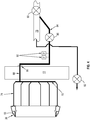
FIG. 4 is a schematic diagram showing the components used to supply heated air to the splitter. - Referring to the drawings wherein identical reference numerals denote the same elements throughout the various views,
FIG. 1 depicts a known type ofturbofan engine 16 mounted in anacelle 18. While the present invention will be described further in the context of a turbofan engine, it will be understood that the principles contained to other types of engines, such as turbojet or turboshaft engines, or other kinds of leading edge structures. - The
engine 16 has a longitudinal axis "A" and includes conventional components including afan 24, a low pressure compressor or "booster" 26 and a low pressure turbine ("LPT") 28, collectively referred to as a "low pressure system", and a high pressure compressor ("HPC") 30, acombustor 32, and a high pressure turbine ("HPT") 34, collectively referred to as a "gas generator" or "core". Various components of thenacelle 18, and stationary structures of theengine 16, including acore nacelle 36, cooperate to define a core flowpath marked with an arrow "F", and a bypass duct marked with an arrow "B". - A stationary annular booster splitter 38 (or simply "splitter") is positioned at the forward end of the
core nacelle 36, between the bypass duct B and the core flowpath F. Thesplitter 38 may be a single continuous ring, or it may be built up from arcuate segments. While a variety of materials such as metal alloys and composites may be used, thesplitter 38 in this example is constructed from a known titanium alloy. - The structure of the
splitter 38 is shown in more detail inFIGS. 2 and3 . Thesplitter 38 has an annularouter wall 40 with a convex-curved, tapered shape that defines aflowpath surface 42. Theflowpath surface 42 includes a radially-outward-facing portion and a radially-inward-facing portion; the two portions are demarcated by an aerodynamic convex-curved leadingedge 44 at the forward end of thesplitter 38. A radially-alignedannular aft bulkhead 46 is disposed at the aft end of thesplitter 38. A radially-aligned annularforward bulkhead 48 is disposed approximately halfway between theaft bulkhead 46 and the leadingedge 44. Theouter wall 40 andbulkheads splitter 38 may be made from materials such as metal alloys or composite materials (for example, carbon-fiber epoxy composites). - An annular, axially-aligned, aft-facing
groove 50 is defined by theouter wall 40 just aft of the leadingedge 44. Anannular step 52 is formed just aft and radially outboard of thegroove 50. - An
annular floorplate 54 extends axially between theouter wall 40 and theforward bulkhead 48. A forward edge of thefloorplate 54 is received in thestep 52. Thefloorplate 54 may be joined to thesplitter 38 by fasteners, welding or brazing, or adhesives. Collectively, the forward portion of theouter wall 40, theforward bulkhead 48, and thefloorplate 54 define a continuous 360degree splitter plenum 56 adjacent the leadingedge 44. - The
splitter 38 is mounted to an annularouter band 58 which circumscribes a row (i.e. a radial array) of airfoil-shaped boosterinlet guide vanes 60. Specifically, aforward rail 62 of theouter band 58 is received in thegroove 50. Theaft bulkhead 46 bears against and is secured to a radially-extendingannular flange 64 of theouter band 58 or adjacent stationary structure, for example using bolts or other mechanical fasteners. - A resilient
annular seal 66 is disposed between theouter band 58 and thefloorplate 54, near the forward end of thefloorplate 54, and serves to mitigate airflow leakage between thefloorplate 54 and theouter band 58. In the illustrated example theseal 66 has a hollow cross-section. - An annular array of spaced-apart
shallow slots 68 or other exhaust passages are formed in the inner surface of theouter wall 40 behind the leadingedge 44 and adjacent theforward rail 62 of theouter band 58. Theslots 68 define a generally "U"-shaped path from thesplitter plenum 56 around theforward rail 62 and communicating with the inboard surface of theouter band 58, through a gap between theouter band 58 and theouter wall 40. Theslots 68 are shaped, sized, and oriented to return heating air to the turbine flowpath at an angle and location selected to minimize aerodynamic disruption. In the illustrated example there is oneslot 68 located between eachinlet guide vane 60. -
FIG. 4 shows schematically components which may be used to supply a uniform flow of heated bleed air to thesplitter plenum 56. Anannular manifold 70 with wyes (also seen schematically inFIG. 1 ) is positioned outside thebooster 26 just forward of an annularfan hub frame 72 of theengine 16. Struts 73 extend radially outward from thefan hub frame 72 to join thenacelle 18. An annular array of feed pipes 74 (which may be thermally insulated) extend axially from themanifold 70 to thesplitter 38. A jumper tube assembly 76 (seen inFIG. 2 ) extends forward from eachfeed pipe 74. - The
engine 16 includes a conventional engineanti-icing duct 78 which takes high-temperature pressured bleed air from the high pressure compressor 30 (in this case from the seventh compressor stage), under the control of a pressure regulating shut-offvalve 80. This air is ducted through apressure regulating valve 82 to the engine's inlet and other conventionally heated structures. Atakeoff duct 84 branches from theanti-icing duct 78 to anactive valve 86 which controls flow through a splitter feed duct 88. The splitter feed duct 88 passes through the fan hub frame 72 (through a boss 90) and feeds the manifold 70. Theactive valve 86 is controlled (for example using a electropneumatic, hydraulic, or electronic controller, not shown) according to an appropriate control law which provides heated air flow under the necessary conditions. In this example,redundant pressure transducers 92 are provided in the splitter feed duct 88 downstream of theactive valve 86. They may be used to verify operation of theactive valve 86. For example, if the active valve is commanded "open", but no pressure increase is sensed by thetransducers 92, this is an indication that theactive valve 86 has failed to actually open. - The jumper tube assemblies 76 are shown in more detail in
FIG. 2 . Each assembly 76 includes ajumper tube 94. Theforward end 96 of thejumper tube 94 passes through theforward bulkhead 48 and at itsaft end 98 passes through theaft bulkhead 46 and couples it to thefeed pipe 74. Thefeed pipes 74 and jumper tube assemblies 76 are arranged to provide circumferentially-consistent air flow to thesplitter plenum 56. In the illustrated example there are six equally-spacedfeed pipes 74 with corresponding jumper tube assemblies 76. - The diameter, length, material, surface finishes and other characteristics of the ducting including the
takeoff duct 84, splitter feed duct 88,manifold 70,feed pipes 74 and jumper tube assemblies 76 may be selected according to known engineering principles to provide appropriate pressure, velocity and flow rate to feed thesplitter plenum 56 as needed for anti-icing operation. - In operation, the
engine 16 will be exposed to icing conditions, namely the presence of moisture in temperatures near the freezing point of water. Ice will naturally tend to form on the leading edge structures including thesplitter 38. As the ice mass builds up, it protrudes into the air flow and increasing aerodynamic (drag) forces act on it, eventually causing portions of it to shed from thesplitter 38. - When necessary to avoid ice buildup or to cause shedding of accreted ice, the
valves manifold 70. Thevalve 86 may be used to reduce the pressure as needed. The heated air is fed into thesplitter plenum 56 through the jumper tube assemblies 76. The air will circulate freely around the circumference of thesplitter plenum 56, heating theouter wall 40, with the heating effect concentrated near the leadingedge 44, where ice shedding is of the greatest concern. This has the effect of reducing or preventing ice buildup and/or causing shedding of already attached ice. Thesplitter plenum 56 may be heated in such a way that ice sheds as relatively small particles which have a reduced tendency to affect engine operation. - The spent heating air exits the
splitter plenum 56 through theslots 68 which redirect the air in such a way as to minimize aerodynamic losses, such as by ejecting it parallel to the streamlines flowing past the inlet guide vanes 60. In this way the cycle penalty for using bleed air to heat thesplitter 38 is reduced. - The splitter configuration described above reduces exposure to the fan air as well as provides a means to distribute heat circumferentially from the hot air injection sites. The invention described herein provides a means of unlimited operation in cold weather. Without the
booster splitter plenum 56, insufficient heat would lead to ice build-up on the splitter lip during airplane ground operation. Upon run up to take-off power the ice shed would produce a stall thus delaying plane departure. A secondary benefit of thebooster splitter plenum 56 is to protect the composite hardware aft of thesplitter 38. Bleed air temperatures from thehigh pressure compressor 30 can reach 530° C (1000° F). By moving the hot air away from the less temperature capable composite parts, this ensures the composite does not degrade. The splitter plenum design reduces the size and weight of tubing required to heat thesplitter 38 as well as the temperature and flow of bleed air needed. - The foregoing has described a heated booster splitter plenum for a gas turbine engine. While specific embodiments of the present invention have been described, it will be apparent to those skilled in the art that various modifications thereto can be made without departing from the scope of the invention. Accordingly, the foregoing description of the preferred embodiment of the invention and the best mode for practicing the invention are provided for the purpose of illustration only.
Claims (15)
- A splitter apparatus for a gas turbine engine, comprising:a splitter (38) including an annular outer wall (40) which defines a convex-curved leading edge at a forward end thereof;an annular floorplate (54) positioned radially inboard of the outer wall (40); andan annular first bulkhead (48) spanning between the outer wall (40) and the floorplate (54), wherein the outer wall (40), the floorplate (54), and the first bulkhead (48) collectively define an annular splitter plenum (56) positioned adjacent the leading edge of the outer wall (40), and wherein at least one exhaust passage (68) formed in the outer wall (40) extends past the floorplate (54) and communicates with the exterior of the splitter (3 8); andat least one jumper tube assembly (76) passing through the first bulkhead (48), each configured to pass air flow from the exterior of the splitter (38) into the plenum.
- The apparatus of claim 1 wherein the exhaust passages (68) comprise a plurality of slots arrayed around the outer wall (40).
- The apparatus of either of claim 1 or 2 further comprising an annular outer band (58) disposed radially inboard of the floorplate (54), and an annular, resilient seal disposed between the floorplate (54) and the outer band (58).
- The apparatus of claim 3 wherein an annular, axially-aligned, aft-facing groove (50) is defined by the outer wall (40) aft of the leading edge, and a forward rail (62) of the outer band (58) is received in the groove (50).
- The apparatus of claim 4 wherein an annular step (52) is formed in the outer wall (40) aft and radially outboard of the groove (50), and a forward edge of the floorplate (54) is received in the step (52).
- The apparatus of any preceding claim wherein each jumper tube assembly (76) is coupled to an axially-extending feed pipe located outside the splitter (38).
- The apparatus of any preceding claim further comprising an annular second bulkhead (46) disposed at an aft end of the splitter (38), wherein each jumper tube assembly (76) passes through the second bulkhead (46).
- A gas turbine engine, comprising:a rotatable fan (24);a rotatable booster (26) disposed aft of the fan (24);a turbomachinery core disposed aft of the booster (26) and operable to generate a flow of pressurized combustion gases;an annular core nacelle (36) surrounding the booster (26) and the turbomachinery core;a low-pressure turbine disposed aft of the turbomachinery core and mechanically coupled to the booster (26) and the fan (24);a radial array of airfoils (60) disposed forward of the booster (26) and circumscribed by an annular outer band (58);a splitter (38) disposed at a forward end of the core nacelle (36) and surrounding the outer band (58), the splitter (38) including:an annular outer wall (40) which defines a convex-curved leading edge at a forward end thereof;an annular floorplate (54) positioned radially inboard of the outer wall (40); andan annular first bulkhead (48) spanning between the outer wall (40) and the floorplate (54), wherein the outer wall (40), the floorplate (54), and the bulkhead collectively define an annular splitter plenum (56) positioned adjacent the leading edge of the outer wall (40), and wherein at least one exhaust passage (68) formed in the outer wall (40) extends past the floorplate (54) and communicates with the exterior of the splitter (3 8); andat least one jumper tube assembly (76) passing through the first bulkhead (48), each configured to pass air flow from the exterior of the splitter (38) into the plenum.
- The gas turbine engine of claim 8 wherein each jumper tube assembly (76) is coupled to an axially-extending feed pipe (74) located aft of the splitter (38).
- The gas turbine engine of either of claim 8 or 9 further comprising:an annular nacelle (18) surrounding the fan (24) and the core nacelle (36);an annular fan hub frame (72) disposed within the core nacelle (36), aft of the booster (26); anda radial array of struts extending between the fan hub frame (72) and the nacelle (18).
- The gas turbine engine of claim 10 further comprising an annular manifold (70) disposed within the core nacelle (36) forward of the fan hub frame (72), the manifold (70) interconnecting the feed pipes (74).
- The gas turbine engine of claim 11 further comprising a splitter feed duct (88) passing axially through the fan hub frame (72) and connected to the manifold (70).
- The gas turbine engine of claim 11 further comprising an anti-icing duct (78) coupled to a source of high-pressure bleed air within the turbomachinery core and to the splitter feed duct (88).
- The gas turbine engine of claim 13 further comprising a valve operable to block or permit flow from the anti-icing duct (78) to the splitter feed duct (88).
- The gas turbine engine of claim 14 further comprising at least one pressure transducer disposed in fluid communication with the splitter feed duct (88).
Applications Claiming Priority (2)
| Application Number | Priority Date | Filing Date | Title |
|---|---|---|---|
| US201161438251P | 2011-01-31 | 2011-01-31 | |
| US13/051,695 US9309781B2 (en) | 2011-01-31 | 2011-03-18 | Heated booster splitter plenum |
Publications (3)
| Publication Number | Publication Date |
|---|---|
| EP2481893A2 true EP2481893A2 (en) | 2012-08-01 |
| EP2481893A3 EP2481893A3 (en) | 2016-07-27 |
| EP2481893B1 EP2481893B1 (en) | 2017-10-25 |
Family
ID=45540823
Family Applications (1)
| Application Number | Title | Priority Date | Filing Date |
|---|---|---|---|
| EP12152801.2A Not-in-force EP2481893B1 (en) | 2011-01-31 | 2012-01-27 | Heated booster splitter plenum |
Country Status (4)
| Country | Link |
|---|---|
| US (1) | US9309781B2 (en) |
| EP (1) | EP2481893B1 (en) |
| JP (1) | JP5997905B2 (en) |
| CA (1) | CA2765672A1 (en) |
Cited By (4)
| Publication number | Priority date | Publication date | Assignee | Title |
|---|---|---|---|---|
| EP3156615A1 (en) * | 2015-10-15 | 2017-04-19 | Safran Aero Boosters SA | De-icing device for a splitter nose of an axial turbine engine compressor |
| FR3082912A1 (en) * | 2018-06-25 | 2019-12-27 | Safran Aircraft Engines | FLUIDIC CONNECTION DEVICE FOR AN AIR CIRCUIT OF AN AIRCRAFT ENGINE |
| WO2020212344A1 (en) * | 2019-04-16 | 2020-10-22 | Safran Aircraft Engines | Separation nozzle for aeronautic turbomachine |
| FR3131939A1 (en) * | 2022-01-18 | 2023-07-21 | Safran Aircraft Engines | AXIAL TURBOMACHINE SPLITTER INCLUDING DEFROST AIR FLOW PASSAGE EXTENDING TO RECTIFIER |
Families Citing this family (18)
| Publication number | Priority date | Publication date | Assignee | Title |
|---|---|---|---|---|
| EP2740905B1 (en) * | 2012-12-07 | 2020-03-18 | Safran Aero Boosters SA | Splitter of an axial turbomachine, corresponding compressor and axial turbomachine |
| FR3004485B1 (en) * | 2013-04-11 | 2015-05-08 | Snecma | DEVICE FOR DEFROSTING AN AERONAUTICAL TURBOMACHINE SEPARATION SPOUT |
| CN105408589B (en) * | 2013-05-07 | 2017-12-26 | 通用电气公司 | Anti-ice diverter head |
| CN104675524B (en) * | 2013-11-27 | 2017-01-18 | 中航商用航空发动机有限责任公司 | Shunting ring, engine anti-icer and turbofan engine |
| BE1022482B1 (en) * | 2014-10-21 | 2016-05-02 | Techspace Aero S.A. | PLASMA DEFROSTING SEPARATION SPOUT FOR AXIAL TURBOMACHINE COMPRESSOR |
| US10030540B2 (en) * | 2014-11-25 | 2018-07-24 | Rolls-Royce North American Technologies Inc. | Fan case liner removal with external heat mat |
| US10421551B2 (en) * | 2014-12-15 | 2019-09-24 | United Technologies Corporation | Aircraft anti-icing system |
| US10156243B2 (en) * | 2015-05-04 | 2018-12-18 | Safran Aero Boosters Sa | Composite splitter lip for axial turbomachine compressor |
| BE1023354B1 (en) * | 2015-08-13 | 2017-02-13 | Safran Aero Boosters S.A. | AXIAL TURBOMACHINE COMPRESSOR DEGIVERANT SEPARATING SPOUT |
| US20170067578A1 (en) * | 2015-09-09 | 2017-03-09 | Honeywell International Inc. | Detection of high stage valve leakage by pressure lockup |
| FR3045010A1 (en) * | 2015-12-15 | 2017-06-16 | Airbus Operations Sas | MULTI-AXIAL TURBOREACTOR AND REAR AIRCRAFT PART PROVIDED WITH SUCH TURBOJET ENGINES |
| US10323571B2 (en) | 2015-12-16 | 2019-06-18 | General Electric Company | Method and system for inlet guide vane heating |
| US10533497B2 (en) * | 2016-04-18 | 2020-01-14 | United Technologies Corporation | Short inlet with integrated liner anti-icing |
| US10189572B2 (en) * | 2016-05-02 | 2019-01-29 | The Boeing Company | Systems and methods for preventing ice formation on portions of an aircraft |
| US11053848B2 (en) | 2018-01-24 | 2021-07-06 | General Electric Company | Additively manufactured booster splitter with integral heating passageways |
| US10822112B2 (en) * | 2018-02-14 | 2020-11-03 | General Electric Company | Slope-based event detection for turbine engines |
| CN113027611A (en) * | 2019-12-24 | 2021-06-25 | 中国航发商用航空发动机有限责任公司 | Split ring anti-icing system and aeroengine |
| CN113047961B (en) * | 2019-12-26 | 2022-05-24 | 中国航发商用航空发动机有限责任公司 | Splitter ring, core machine and aircraft engine |
Family Cites Families (28)
| Publication number | Priority date | Publication date | Assignee | Title |
|---|---|---|---|---|
| GB458862A (en) | 1935-06-26 | 1936-12-28 | Henderik Van Der Horst | A new or improved method of and means for preventing the formation of ice on aircraft |
| JPS61160395A (en) | 1985-01-09 | 1986-07-21 | 財団法人日本航空機開発協会 | Deicer for aircraft |
| US4782658A (en) | 1987-05-07 | 1988-11-08 | Rolls-Royce Plc | Deicing of a geared gas turbine engine |
| US4966229A (en) | 1989-12-26 | 1990-10-30 | United Technologies Corporation | Leading edge heat pipe arrangement |
| US5763249A (en) | 1991-12-09 | 1998-06-09 | The Regents Of The University Of California | Antibody-mediated reduction of α-ketoamides |
| US5736249A (en) | 1994-08-16 | 1998-04-07 | Decora, Incorporated | Non-stick polymer-coated articles of manufacture |
| US6171704B1 (en) | 1995-12-29 | 2001-01-09 | Sermatech International, Inc. | Coating for aerospace aluminum parts |
| US6258758B1 (en) | 1996-04-26 | 2001-07-10 | Platinum Research Organization Llc | Catalyzed surface composition altering and surface coating formulations and methods |
| JP2002206087A (en) | 2000-03-02 | 2002-07-26 | Mitsunori Yoshida | Composition for snow and ice prevention member and snow and ice prevention member using the same |
| US6561760B2 (en) * | 2001-08-17 | 2003-05-13 | General Electric Company | Booster compressor deicer |
| US6809169B2 (en) | 2002-06-07 | 2004-10-26 | The Boeing Company | Polysiloxane coatings for surfaces |
| US7202321B2 (en) | 2002-06-07 | 2007-04-10 | The Boeing Company | Method and composition for sealing components and components sealed thereby |
| US6797795B2 (en) | 2002-06-07 | 2004-09-28 | The Boeing Company | Polysiloxane(amide-ureide) anti-ice coating |
| US6725645B1 (en) | 2002-10-03 | 2004-04-27 | General Electric Company | Turbofan engine internal anti-ice device |
| US20060257663A1 (en) | 2003-03-03 | 2006-11-16 | Doll Gary L | Wear resistant coatings to reduce ice adhesion on air foils |
| US7131612B2 (en) * | 2003-07-29 | 2006-11-07 | Pratt & Whitney Canada Corp. | Nacelle inlet lip anti-icing with engine oil |
| EP1747144B1 (en) * | 2004-05-12 | 2009-05-06 | Vestergaard Company A/S | Spray-regulating system incorporated in aircraft anti-icers |
| WO2006024032A2 (en) | 2004-08-24 | 2006-03-02 | Waters Investments Limited | Devices and methods for preventing ice build-up and articles of manufacture that are resistant to ice build-up |
| US20060281861A1 (en) | 2005-06-13 | 2006-12-14 | Putnam John W | Erosion resistant anti-icing coatings |
| US7624581B2 (en) * | 2005-12-21 | 2009-12-01 | General Electric Company | Compact booster bleed turbofan |
| US7900438B2 (en) | 2006-07-28 | 2011-03-08 | General Electric Company | Heat transfer system and method for turbine engine using heat pipes |
| US7900437B2 (en) | 2006-07-28 | 2011-03-08 | General Electric Company | Heat transfer system and method for turbine engine using heat pipes |
| US8205426B2 (en) * | 2006-07-31 | 2012-06-26 | General Electric Company | Method and apparatus for operating gas turbine engines |
| US7823374B2 (en) | 2006-08-31 | 2010-11-02 | General Electric Company | Heat transfer system and method for turbine engine using heat pipes |
| US7845159B2 (en) | 2006-08-31 | 2010-12-07 | General Electric Company | Heat pipe-based cooling apparatus and method for turbine engine |
| US8015788B2 (en) * | 2006-12-27 | 2011-09-13 | General Electric Company | Heat transfer system for turbine engine using heat pipes |
| FR2921901B1 (en) * | 2007-10-08 | 2011-03-18 | Aircelle Sa | AIR INTAKE STRUCTURE CAPABLE OF BEING MOUNTED BEFORE MEDIUM NACELLE STRUCTURE FOR AN AIRCRAFT ENGINE, AND NACELLE EQUIPPED WITH SUCH AN AIR INTAKE STRUCTURE |
| US7938368B2 (en) | 2008-04-07 | 2011-05-10 | United Technologies Corporation | Nosecone ice protection system for a gas turbine engine |
-
2011
- 2011-03-18 US US13/051,695 patent/US9309781B2/en active Active
-
2012
- 2012-01-26 CA CA2765672A patent/CA2765672A1/en not_active Abandoned
- 2012-01-26 JP JP2012013598A patent/JP5997905B2/en not_active Expired - Fee Related
- 2012-01-27 EP EP12152801.2A patent/EP2481893B1/en not_active Not-in-force
Non-Patent Citations (1)
| Title |
|---|
| None |
Cited By (9)
| Publication number | Priority date | Publication date | Assignee | Title |
|---|---|---|---|---|
| EP3156615A1 (en) * | 2015-10-15 | 2017-04-19 | Safran Aero Boosters SA | De-icing device for a splitter nose of an axial turbine engine compressor |
| BE1023531B1 (en) * | 2015-10-15 | 2017-04-25 | Safran Aero Boosters S.A. | AXIAL TURBOMACHINE COMPRESSOR SEPARATION SEPARATION DEVICE DEGIVER DEVICE |
| US10060351B2 (en) | 2015-10-15 | 2018-08-28 | Safran Aero Boosters Sa | De-icing device for a splitter nose of an axial turbine engine compressor |
| FR3082912A1 (en) * | 2018-06-25 | 2019-12-27 | Safran Aircraft Engines | FLUIDIC CONNECTION DEVICE FOR AN AIR CIRCUIT OF AN AIRCRAFT ENGINE |
| WO2020212344A1 (en) * | 2019-04-16 | 2020-10-22 | Safran Aircraft Engines | Separation nozzle for aeronautic turbomachine |
| FR3095230A1 (en) * | 2019-04-16 | 2020-10-23 | Safran Aircraft Engines | DEFROST DEVICE |
| US11982195B2 (en) | 2019-04-16 | 2024-05-14 | Safran Aircraft Engines | Separation nozzle for aeronautic turbomachine |
| US12577888B2 (en) | 2019-04-16 | 2026-03-17 | Safran Aircraft Engines | Splitter for aeronautic turbomachine |
| FR3131939A1 (en) * | 2022-01-18 | 2023-07-21 | Safran Aircraft Engines | AXIAL TURBOMACHINE SPLITTER INCLUDING DEFROST AIR FLOW PASSAGE EXTENDING TO RECTIFIER |
Also Published As
| Publication number | Publication date |
|---|---|
| EP2481893A3 (en) | 2016-07-27 |
| CA2765672A1 (en) | 2012-07-31 |
| US20120192544A1 (en) | 2012-08-02 |
| JP2012189077A (en) | 2012-10-04 |
| EP2481893B1 (en) | 2017-10-25 |
| JP5997905B2 (en) | 2016-09-28 |
| US9309781B2 (en) | 2016-04-12 |
Similar Documents
| Publication | Publication Date | Title |
|---|---|---|
| EP2481893B1 (en) | Heated booster splitter plenum | |
| US9777632B2 (en) | Anti-ice splitter nose | |
| US11092013B2 (en) | Modulated turbine cooling system | |
| EP2472062B1 (en) | Gas turbine engine and airfoil | |
| EP2805022B1 (en) | Gas turbine bypass vane system, gas turbine engine and method for manufacturing a bypass vane stage | |
| US8245981B2 (en) | Ice shed reduction for leading edge structures | |
| US20170268430A1 (en) | Engine bleed system with turbo-compressor | |
| JP2004124947A (en) | Internal ice protection device for turbofan engine | |
| US20120177480A1 (en) | Rotor with cooling passage | |
| WO2013102135A2 (en) | Gas turbine engine and turbine blade | |
| Barbosa | Ultra high bypass ratio engine technology review-the efficiency frontier for the turbofanpropulsion | |
| US11674438B1 (en) | Thermal management system | |
| EP3029272B1 (en) | Nozzle support systems | |
| US11913355B2 (en) | Part-span shrouds for pitch controlled aircrafts | |
| US12497895B1 (en) | Air cooling system for stator vane structure outer platform | |
| US12565855B1 (en) | Gas turbine engine | |
| US12460552B1 (en) | Sealing system for a turbomachine | |
| PICKERELL | The Rolls-Royce three-shaft turbofan engine |
Legal Events
| Date | Code | Title | Description |
|---|---|---|---|
| PUAI | Public reference made under article 153(3) epc to a published international application that has entered the european phase |
Free format text: ORIGINAL CODE: 0009012 |
|
| AK | Designated contracting states |
Kind code of ref document: A2 Designated state(s): AL AT BE BG CH CY CZ DE DK EE ES FI FR GB GR HR HU IE IS IT LI LT LU LV MC MK MT NL NO PL PT RO RS SE SI SK SM TR |
|
| AX | Request for extension of the european patent |
Extension state: BA ME |
|
| PUAL | Search report despatched |
Free format text: ORIGINAL CODE: 0009013 |
|
| AK | Designated contracting states |
Kind code of ref document: A3 Designated state(s): AL AT BE BG CH CY CZ DE DK EE ES FI FR GB GR HR HU IE IS IT LI LT LU LV MC MK MT NL NO PL PT RO RS SE SI SK SM TR |
|
| AX | Request for extension of the european patent |
Extension state: BA ME |
|
| RIC1 | Information provided on ipc code assigned before grant |
Ipc: F02C 7/047 20060101ALI20160620BHEP Ipc: F02K 3/06 20060101ALI20160620BHEP Ipc: F01D 25/02 20060101AFI20160620BHEP |
|
| 17P | Request for examination filed |
Effective date: 20170127 |
|
| RBV | Designated contracting states (corrected) |
Designated state(s): AL AT BE BG CH CY CZ DE DK EE ES FI FR GB GR HR HU IE IS IT LI LT LU LV MC MK MT NL NO PL PT RO RS SE SI SK SM TR |
|
| GRAP | Despatch of communication of intention to grant a patent |
Free format text: ORIGINAL CODE: EPIDOSNIGR1 |
|
| RIC1 | Information provided on ipc code assigned before grant |
Ipc: F02K 3/06 20060101ALI20170531BHEP Ipc: F02C 7/047 20060101ALI20170531BHEP Ipc: F01D 25/02 20060101AFI20170531BHEP Ipc: B64D 15/04 20060101ALI20170531BHEP |
|
| INTG | Intention to grant announced |
Effective date: 20170627 |
|
| GRAS | Grant fee paid |
Free format text: ORIGINAL CODE: EPIDOSNIGR3 |
|
| GRAA | (expected) grant |
Free format text: ORIGINAL CODE: 0009210 |
|
| AK | Designated contracting states |
Kind code of ref document: B1 Designated state(s): AL AT BE BG CH CY CZ DE DK EE ES FI FR GB GR HR HU IE IS IT LI LT LU LV MC MK MT NL NO PL PT RO RS SE SI SK SM TR |
|
| REG | Reference to a national code |
Ref country code: GB Ref legal event code: FG4D |
|
| REG | Reference to a national code |
Ref country code: CH Ref legal event code: EP |
|
| REG | Reference to a national code |
Ref country code: AT Ref legal event code: REF Ref document number: 940162 Country of ref document: AT Kind code of ref document: T Effective date: 20171115 |
|
| REG | Reference to a national code |
Ref country code: IE Ref legal event code: FG4D |
|
| REG | Reference to a national code |
Ref country code: DE Ref legal event code: R096 Ref document number: 602012038836 Country of ref document: DE |
|
| REG | Reference to a national code |
Ref country code: NL Ref legal event code: MP Effective date: 20171025 |
|
| REG | Reference to a national code |
Ref country code: LT Ref legal event code: MG4D |
|
| REG | Reference to a national code |
Ref country code: AT Ref legal event code: MK05 Ref document number: 940162 Country of ref document: AT Kind code of ref document: T Effective date: 20171025 |
|
| PG25 | Lapsed in a contracting state [announced via postgrant information from national office to epo] |
Ref country code: NL Free format text: LAPSE BECAUSE OF FAILURE TO SUBMIT A TRANSLATION OF THE DESCRIPTION OR TO PAY THE FEE WITHIN THE PRESCRIBED TIME-LIMIT Effective date: 20171025 |
|
| PG25 | Lapsed in a contracting state [announced via postgrant information from national office to epo] |
Ref country code: ES Free format text: LAPSE BECAUSE OF FAILURE TO SUBMIT A TRANSLATION OF THE DESCRIPTION OR TO PAY THE FEE WITHIN THE PRESCRIBED TIME-LIMIT Effective date: 20171025 Ref country code: SE Free format text: LAPSE BECAUSE OF FAILURE TO SUBMIT A TRANSLATION OF THE DESCRIPTION OR TO PAY THE FEE WITHIN THE PRESCRIBED TIME-LIMIT Effective date: 20171025 Ref country code: FI Free format text: LAPSE BECAUSE OF FAILURE TO SUBMIT A TRANSLATION OF THE DESCRIPTION OR TO PAY THE FEE WITHIN THE PRESCRIBED TIME-LIMIT Effective date: 20171025 Ref country code: LT Free format text: LAPSE BECAUSE OF FAILURE TO SUBMIT A TRANSLATION OF THE DESCRIPTION OR TO PAY THE FEE WITHIN THE PRESCRIBED TIME-LIMIT Effective date: 20171025 Ref country code: NO Free format text: LAPSE BECAUSE OF FAILURE TO SUBMIT A TRANSLATION OF THE DESCRIPTION OR TO PAY THE FEE WITHIN THE PRESCRIBED TIME-LIMIT Effective date: 20180125 |
|
| PG25 | Lapsed in a contracting state [announced via postgrant information from national office to epo] |
Ref country code: BG Free format text: LAPSE BECAUSE OF FAILURE TO SUBMIT A TRANSLATION OF THE DESCRIPTION OR TO PAY THE FEE WITHIN THE PRESCRIBED TIME-LIMIT Effective date: 20180125 Ref country code: IS Free format text: LAPSE BECAUSE OF FAILURE TO SUBMIT A TRANSLATION OF THE DESCRIPTION OR TO PAY THE FEE WITHIN THE PRESCRIBED TIME-LIMIT Effective date: 20180225 Ref country code: AT Free format text: LAPSE BECAUSE OF FAILURE TO SUBMIT A TRANSLATION OF THE DESCRIPTION OR TO PAY THE FEE WITHIN THE PRESCRIBED TIME-LIMIT Effective date: 20171025 Ref country code: LV Free format text: LAPSE BECAUSE OF FAILURE TO SUBMIT A TRANSLATION OF THE DESCRIPTION OR TO PAY THE FEE WITHIN THE PRESCRIBED TIME-LIMIT Effective date: 20171025 Ref country code: HR Free format text: LAPSE BECAUSE OF FAILURE TO SUBMIT A TRANSLATION OF THE DESCRIPTION OR TO PAY THE FEE WITHIN THE PRESCRIBED TIME-LIMIT Effective date: 20171025 Ref country code: GR Free format text: LAPSE BECAUSE OF FAILURE TO SUBMIT A TRANSLATION OF THE DESCRIPTION OR TO PAY THE FEE WITHIN THE PRESCRIBED TIME-LIMIT Effective date: 20180126 Ref country code: RS Free format text: LAPSE BECAUSE OF FAILURE TO SUBMIT A TRANSLATION OF THE DESCRIPTION OR TO PAY THE FEE WITHIN THE PRESCRIBED TIME-LIMIT Effective date: 20171025 |
|
| REG | Reference to a national code |
Ref country code: DE Ref legal event code: R097 Ref document number: 602012038836 Country of ref document: DE |
|
| PG25 | Lapsed in a contracting state [announced via postgrant information from national office to epo] |
Ref country code: CZ Free format text: LAPSE BECAUSE OF FAILURE TO SUBMIT A TRANSLATION OF THE DESCRIPTION OR TO PAY THE FEE WITHIN THE PRESCRIBED TIME-LIMIT Effective date: 20171025 Ref country code: CY Free format text: LAPSE BECAUSE OF FAILURE TO SUBMIT A TRANSLATION OF THE DESCRIPTION OR TO PAY THE FEE WITHIN THE PRESCRIBED TIME-LIMIT Effective date: 20171025 Ref country code: DK Free format text: LAPSE BECAUSE OF FAILURE TO SUBMIT A TRANSLATION OF THE DESCRIPTION OR TO PAY THE FEE WITHIN THE PRESCRIBED TIME-LIMIT Effective date: 20171025 Ref country code: EE Free format text: LAPSE BECAUSE OF FAILURE TO SUBMIT A TRANSLATION OF THE DESCRIPTION OR TO PAY THE FEE WITHIN THE PRESCRIBED TIME-LIMIT Effective date: 20171025 Ref country code: SK Free format text: LAPSE BECAUSE OF FAILURE TO SUBMIT A TRANSLATION OF THE DESCRIPTION OR TO PAY THE FEE WITHIN THE PRESCRIBED TIME-LIMIT Effective date: 20171025 |
|
| REG | Reference to a national code |
Ref country code: DE Ref legal event code: R119 Ref document number: 602012038836 Country of ref document: DE |
|
| PG25 | Lapsed in a contracting state [announced via postgrant information from national office to epo] |
Ref country code: RO Free format text: LAPSE BECAUSE OF FAILURE TO SUBMIT A TRANSLATION OF THE DESCRIPTION OR TO PAY THE FEE WITHIN THE PRESCRIBED TIME-LIMIT Effective date: 20171025 Ref country code: IT Free format text: LAPSE BECAUSE OF FAILURE TO SUBMIT A TRANSLATION OF THE DESCRIPTION OR TO PAY THE FEE WITHIN THE PRESCRIBED TIME-LIMIT Effective date: 20171025 Ref country code: PL Free format text: LAPSE BECAUSE OF FAILURE TO SUBMIT A TRANSLATION OF THE DESCRIPTION OR TO PAY THE FEE WITHIN THE PRESCRIBED TIME-LIMIT Effective date: 20171025 Ref country code: SM Free format text: LAPSE BECAUSE OF FAILURE TO SUBMIT A TRANSLATION OF THE DESCRIPTION OR TO PAY THE FEE WITHIN THE PRESCRIBED TIME-LIMIT Effective date: 20171025 |
|
| PLBE | No opposition filed within time limit |
Free format text: ORIGINAL CODE: 0009261 |
|
| REG | Reference to a national code |
Ref country code: CH Ref legal event code: PL |
|
| STAA | Information on the status of an ep patent application or granted ep patent |
Free format text: STATUS: NO OPPOSITION FILED WITHIN TIME LIMIT |
|
| GBPC | Gb: european patent ceased through non-payment of renewal fee |
Effective date: 20180127 |
|
| 26N | No opposition filed |
Effective date: 20180726 |
|
| PG25 | Lapsed in a contracting state [announced via postgrant information from national office to epo] |
Ref country code: LU Free format text: LAPSE BECAUSE OF NON-PAYMENT OF DUE FEES Effective date: 20180127 Ref country code: DE Free format text: LAPSE BECAUSE OF NON-PAYMENT OF DUE FEES Effective date: 20180801 Ref country code: FR Free format text: LAPSE BECAUSE OF NON-PAYMENT OF DUE FEES Effective date: 20180131 |
|
| REG | Reference to a national code |
Ref country code: IE Ref legal event code: MM4A |
|
| REG | Reference to a national code |
Ref country code: FR Ref legal event code: ST Effective date: 20180928 |
|
| REG | Reference to a national code |
Ref country code: BE Ref legal event code: MM Effective date: 20180131 |
|
| PG25 | Lapsed in a contracting state [announced via postgrant information from national office to epo] |
Ref country code: LI Free format text: LAPSE BECAUSE OF NON-PAYMENT OF DUE FEES Effective date: 20180131 Ref country code: CH Free format text: LAPSE BECAUSE OF NON-PAYMENT OF DUE FEES Effective date: 20180131 Ref country code: GB Free format text: LAPSE BECAUSE OF NON-PAYMENT OF DUE FEES Effective date: 20180127 Ref country code: BE Free format text: LAPSE BECAUSE OF NON-PAYMENT OF DUE FEES Effective date: 20180131 Ref country code: SI Free format text: LAPSE BECAUSE OF FAILURE TO SUBMIT A TRANSLATION OF THE DESCRIPTION OR TO PAY THE FEE WITHIN THE PRESCRIBED TIME-LIMIT Effective date: 20171025 |
|
| PG25 | Lapsed in a contracting state [announced via postgrant information from national office to epo] |
Ref country code: IE Free format text: LAPSE BECAUSE OF NON-PAYMENT OF DUE FEES Effective date: 20180127 |
|
| PG25 | Lapsed in a contracting state [announced via postgrant information from national office to epo] |
Ref country code: MC Free format text: LAPSE BECAUSE OF FAILURE TO SUBMIT A TRANSLATION OF THE DESCRIPTION OR TO PAY THE FEE WITHIN THE PRESCRIBED TIME-LIMIT Effective date: 20171025 |
|
| PG25 | Lapsed in a contracting state [announced via postgrant information from national office to epo] |
Ref country code: MT Free format text: LAPSE BECAUSE OF NON-PAYMENT OF DUE FEES Effective date: 20180127 |
|
| PG25 | Lapsed in a contracting state [announced via postgrant information from national office to epo] |
Ref country code: TR Free format text: LAPSE BECAUSE OF FAILURE TO SUBMIT A TRANSLATION OF THE DESCRIPTION OR TO PAY THE FEE WITHIN THE PRESCRIBED TIME-LIMIT Effective date: 20171025 |
|
| PG25 | Lapsed in a contracting state [announced via postgrant information from national office to epo] |
Ref country code: PT Free format text: LAPSE BECAUSE OF FAILURE TO SUBMIT A TRANSLATION OF THE DESCRIPTION OR TO PAY THE FEE WITHIN THE PRESCRIBED TIME-LIMIT Effective date: 20171025 Ref country code: HU Free format text: LAPSE BECAUSE OF FAILURE TO SUBMIT A TRANSLATION OF THE DESCRIPTION OR TO PAY THE FEE WITHIN THE PRESCRIBED TIME-LIMIT; INVALID AB INITIO Effective date: 20120127 |
|
| PG25 | Lapsed in a contracting state [announced via postgrant information from national office to epo] |
Ref country code: MK Free format text: LAPSE BECAUSE OF NON-PAYMENT OF DUE FEES Effective date: 20171025 |
|
| PG25 | Lapsed in a contracting state [announced via postgrant information from national office to epo] |
Ref country code: AL Free format text: LAPSE BECAUSE OF FAILURE TO SUBMIT A TRANSLATION OF THE DESCRIPTION OR TO PAY THE FEE WITHIN THE PRESCRIBED TIME-LIMIT Effective date: 20171025 |