EP2481884A2 - Method and system for controlling thermal differential in turbine systems - Google Patents
Method and system for controlling thermal differential in turbine systems Download PDFInfo
- Publication number
- EP2481884A2 EP2481884A2 EP12152343A EP12152343A EP2481884A2 EP 2481884 A2 EP2481884 A2 EP 2481884A2 EP 12152343 A EP12152343 A EP 12152343A EP 12152343 A EP12152343 A EP 12152343A EP 2481884 A2 EP2481884 A2 EP 2481884A2
- Authority
- EP
- European Patent Office
- Prior art keywords
- turbine rotor
- compressor
- turbine
- barrier coating
- thermal barrier
- Prior art date
- Legal status (The legal status is an assumption and is not a legal conclusion. Google has not performed a legal analysis and makes no representation as to the accuracy of the status listed.)
- Granted
Links
- 238000000034 method Methods 0.000 title claims description 23
- 239000012720 thermal barrier coating Substances 0.000 claims abstract description 38
- 239000003570 air Substances 0.000 description 5
- 230000035882 stress Effects 0.000 description 5
- 230000001052 transient effect Effects 0.000 description 5
- 230000008646 thermal stress Effects 0.000 description 3
- 239000012080 ambient air Substances 0.000 description 2
- 239000000567 combustion gas Substances 0.000 description 2
- 230000007423 decrease Effects 0.000 description 2
- 230000003247 decreasing effect Effects 0.000 description 2
- 238000010304 firing Methods 0.000 description 2
- 239000000446 fuel Substances 0.000 description 2
- 239000000203 mixture Substances 0.000 description 2
- 230000003068 static effect Effects 0.000 description 2
- 230000004888 barrier function Effects 0.000 description 1
- 238000005452 bending Methods 0.000 description 1
- 239000000919 ceramic Substances 0.000 description 1
- 238000001816 cooling Methods 0.000 description 1
- 230000007717 exclusion Effects 0.000 description 1
- 239000000284 extract Substances 0.000 description 1
- 230000006870 function Effects 0.000 description 1
- 239000000463 material Substances 0.000 description 1
- 238000011144 upstream manufacturing Methods 0.000 description 1
Images
Classifications
-
- F—MECHANICAL ENGINEERING; LIGHTING; HEATING; WEAPONS; BLASTING
- F01—MACHINES OR ENGINES IN GENERAL; ENGINE PLANTS IN GENERAL; STEAM ENGINES
- F01D—NON-POSITIVE DISPLACEMENT MACHINES OR ENGINES, e.g. STEAM TURBINES
- F01D5/00—Blades; Blade-carrying members; Heating, heat-insulating, cooling or antivibration means on the blades or the members
- F01D5/02—Blade-carrying members, e.g. rotors
- F01D5/08—Heating, heat-insulating or cooling means
-
- F—MECHANICAL ENGINEERING; LIGHTING; HEATING; WEAPONS; BLASTING
- F05—INDEXING SCHEMES RELATING TO ENGINES OR PUMPS IN VARIOUS SUBCLASSES OF CLASSES F01-F04
- F05D—INDEXING SCHEME FOR ASPECTS RELATING TO NON-POSITIVE-DISPLACEMENT MACHINES OR ENGINES, GAS-TURBINES OR JET-PROPULSION PLANTS
- F05D2230/00—Manufacture
- F05D2230/90—Coating; Surface treatment
-
- Y—GENERAL TAGGING OF NEW TECHNOLOGICAL DEVELOPMENTS; GENERAL TAGGING OF CROSS-SECTIONAL TECHNOLOGIES SPANNING OVER SEVERAL SECTIONS OF THE IPC; TECHNICAL SUBJECTS COVERED BY FORMER USPC CROSS-REFERENCE ART COLLECTIONS [XRACs] AND DIGESTS
- Y02—TECHNOLOGIES OR APPLICATIONS FOR MITIGATION OR ADAPTATION AGAINST CLIMATE CHANGE
- Y02T—CLIMATE CHANGE MITIGATION TECHNOLOGIES RELATED TO TRANSPORTATION
- Y02T50/00—Aeronautics or air transport
- Y02T50/60—Efficient propulsion technologies, e.g. for aircraft
Definitions
- the subject matter disclosed herein relates generally to turbine systems and, more particularly, to methods and systems for controlling thermal differential in turbine systems.
- At least some known turbine systems include a compressor that compresses air channeled downstream through the turbine system.
- a compressor that compresses air channeled downstream through the turbine system.
- at least some portions of such compressors and/or rotors may be subjected to high temperatures, thermal gradients, high stresses, and/or vibrations.
- at least some known compressors include a plurality of stages that increasingly compress and, consequently, increase a temperature of air channeled therethrough. Such differences in airflow temperature may result in thermal gradients developing within the compressor.
- at least some surfaces are exposed to the flow path more than other portions of the compressor. As a result, other thermal gradients may develop within compressor.
- Such thermal gradients and/or thermal stresses may cause uneven expansion, bending, and/or other stresses within the compressor that, at times, could lead to undesired slipping and/or rubbing of compressor components.
- a compressor discharge temperature, a firing temperature, and/or a core flow rate may be increased.
- increasing any of the aforementioned operational characteristics could increase the likelihood of thermal gradients and/or thermal stresses being developed within the compressor and/or the rotor.
- the invention resides in a turbine rotor for use with a turbine system.
- the turbine rotor includes a surface proximate to a wheel rim of the turbine rotor and a thermal barrier coating applied to the surface.
- the invention also resides in a turbine system including a turbine rotor described above.
- the invention resides in a method for controlling a thermal differential within a turbine rotor for use with a turbine system.
- the method includes selecting a surface of the turbine rotor proximate to a wheel rim of the turbine rotor and applying a thermal barrier coating to the surface of the turbine rotor.
- a thermal barrier coating is applied to at least one surface of the turbine rotor, wherein the surface is selected based on stress levels, transient thermal gradients, and/or surrounding heat transfer environment. Applying the thermal barrier coating to such surfaces facilitates controlling transient thermal stresses within the turbine rotor and, thus, facilitates increasing a useful operating life of the turbine system.
- the turbine rotor surface may be disposed within a compressor and/or a turbine section of the turbine system.
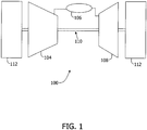
- FIG. 1 is a schematic illustration of an exemplary turbine system 100.
- turbine system 100 includes, coupled in serial flow arrangement, a compressor 104, a combustor assembly 106, and a turbine 108 that is rotatably coupled to compressor 104 via a rotor shaft 110.
- ambient air is channeled through an air inlet towards compressor 104.
- the ambient air is then compressed by compressor 104 prior to being directed towards combustor assembly 106.
- compressed air within combustor assembly 106 is mixed with fuel, and the resulting fuel-air mixture is then ignited within combustor assembly 106 to generate combustion gases that are directed towards turbine 108.
- turbine 108 extracts rotational energy from the combustion gases and rotates rotor shaft 110 to drive compressor 104.
- turbine system 100 drives a load 112, such as a generator, coupled to rotor shaft 110.
- load 112 is positioned downstream of turbine system 100.
- load 112 may be positioned downstream of turbine system 100.
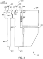
- FIG. 2 is a cross-sectional illustration of a portion of a turbine rotor or, more specifically, compressor 104.
- compressor 104 includes a plurality of stages 230 that include at least a first stage 232 and a second stage 234 that is positioned downstream from first stage 232.
- each stage 230 includes at least one rotor disc 240 that is formed with a disc web 242 bounded circumferentially by a wheel rim 244.
- compressor 104 includes a circumferential slot 262 that is oriented to channel a portion 224 of airflow 220 in a circumferential direction, and a radial slot 264 that is oriented to channel a portion 222 of airflow 220 in a radial direction. More specifically, in the exemplary embodiment, airflow portion 224 is directed through circumferential slot 262, and airflow portion 222 is directed through radial slot 264. In the exemplary embodiment, slots 262 and/or 264 facilitate cooling portions of compressor 104 that are proximate to wheel rim 244 and/or combustor assembly 106.
- compressor 104 includes a rim aft face 270 that is downstream from stages 230 and discs 240. More specifically, in the exemplary embodiment, rim aft face 270 is between wheels 240 and combustor assembly 106. As such, in the exemplary embodiment, rim aft face 270 provides a buffer area between compressor 104 and combustor assembly 106, to facilitate shielding relatively hot air-fuel mixtures ignited in combustor assembly 106.
- compressor 104 In the exemplary embodiment, at least some sections and/or portions of compressor 104 are subjected and/or exposed to higher temperatures than other sections and/or portions. Moreover, within such sections and/or portions, at least some surfaces of compressor 104 are exposed to airflow 220 and/or higher temperatures more than other portions of compressor 104.
- disc rim 244 has more exposure to airflow 220 than a disc bore and/or disc web 242.
- compressor 104 includes a dovetail slot and loading locations 250 sized and/or oriented to receive an airfoil (not shown) therein. In the exemplary embodiment, slot and loading locations 250 is exposed to higher temperatures than other portions of compressor 104.
- a thermal barrier coating (TBC) 210 is applied to at least some high heat transfer and/or high temperature regions of compressor 104 including, for example, disc rim 244 to facilitate controlling a thermal differential within compressor 104.
- TBC 210 facilitates shielding at least some of these surfaces within compressor 104 from relatively high temperatures and/or heat transfer convention coefficient.
- TBC 210 is fabricated from a material having a thermal conductivity that is suitable to enable turbine system 100 to function as described herein.
- TBC 210 may be fabricated from, without limitation, ceramics and/or sprayed oxides.
- TBC 210 may be applied to any suitable rotor and/or static structure within turbine system 100. Additional surfaces for application of TBC 210 may be selected based on various factors including, but not limited to, stress levels, transient thermal gradients, and/or a surrounding heat transfer environment. For example, in the exemplary embodiment, TBC 210 shields the outer surfaces of each stage 230 of compressor 104 including disc rim 244, slot and loading locations 250, slots 262 and 264, and/or rim aft face 270 from exposure to high temperatures of airflow 220.
- TBC 210 is applied with a thickness that is suitable to provide a thermal barrier without substantially affecting airflow 220 within compressor 104.
- TBC 210 has a thickness of less than approximately 0.04 inches.
- TBC 210 has a thickness of less than approximately 0.02 inches. More particularly, TBC 210 has a thickness of less than approximately 0.005 inches.
- TBC 210 may have a thickness of greater than or equal to approximately 0.04 inches.
- airflow 220 upstream from first stage 232 may be approximately 700-800 °F while airflow 220 downstream from second state 234 may be approximately 750-850 °F.
- a portion of airflow 220 is directed through slots 262 and 264. More specifically, in the exemplary embodiment, airflow portion 224 flows circumferentially within compressor 104, and airflow portion 222 flows radially outward within compressor 104.
- a compressor discharge is directed through rim aft face 270 towards combustor assembly 106.
- the compressor discharge temperature may be greater than approximately 800 °F.
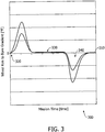
- FIG. 3 is a graph 300 illustrating an exemplary temperature difference, or a delta temperature 310, of a surface protected by TBC 210 during operation of turbine rotor or, more specifically, compressor 104. More specifically, the X-axis is representative of a mission time measured in seconds, and the Y-axis is representative of a difference in temperature between wheel rim 244 and bore 242. As shown in FIG. 3 , the mission time includes three stages to the operating cycle of turbine system 100: a startup 320, a main operating stage 330, and a shutdown 340.
- compressor 104 is subjected to a quick increase in temperature. Accordingly, surfaces within compressor 104 may be subjected to a relatively quick increase in delta temperature 310, as is indicated by the spike in delta temperature 310.
- TBC 210 facilitates reducing delta temperature 310 during startup 320 as compared to a compressor 104 without TBC 210. As such, TBC 210 facilitates reducing a transient response rate during startup 320 of turbine system 100.
- delta temperature 310 decreases relatively steadily.
- the operating temperature of compressor 104 is relatively steady and, thus, during main operating stage 330, delta temperature 310 is relatively constant at approximately 0 °F.
- compressor 104 is subjected to a quick decrease in temperature. Accordingly, surfaces within compressor 104 may be subjected to a relatively quick increase in delta temperature 310 in a negative direction, as is indicated by the dip in delta temperature 310.
- TBC 210 facilitates decreasing delta temperature 310 during shutdown 340 as compared to a compressor 104 without TBC 210. In the exemplary embodiment, delta temperature 310 increases overtime until compressor 104 is cooled down. As such, TBC 210 facilitates reducing a transient response rate during shutdown 340 of turbine system 100.
- the exemplary methods and systems described herein facilitate controlling a rotor thermal differential of a turbine rotor and/or turbine system.
- the exemplary methods and systems facilitate decreasing stresses and, therefore, increasing an operating life of the turbine rotor and/or a turbine system.
- the methods and systems described herein may enable the compressor to have high compressor discharge temperatures, firing temperatures, and/or core flow rates, thereby increasing an efficiency of turbine system as well as faster operational cycles.
- controlling such temperature differences of the turbine rotor facilitates reducing thermal gradients, which may result in reducing undesired slipping and/or rubbing of rotor and/or static components.
- Exemplary embodiments of methods and systems are described and/or illustrated herein in detail.
- the exemplary systems and methods are not limited to the specific embodiments described herein, but rather, components of each system and/or steps of each method may be utilized independently and separately from other components and/or method steps described herein.
- Each component and each method step may also be used in combination with other components and/or method steps.
Abstract
Description
- The subject matter disclosed herein relates generally to turbine systems and, more particularly, to methods and systems for controlling thermal differential in turbine systems.
- At least some known turbine systems include a compressor that compresses air channeled downstream through the turbine system. During startup operations and/or shutdown of at least some known turbine systems, at least some portions of such compressors and/or rotors may be subjected to high temperatures, thermal gradients, high stresses, and/or vibrations. For example at least some known compressors include a plurality of stages that increasingly compress and, consequently, increase a temperature of air channeled therethrough. Such differences in airflow temperature may result in thermal gradients developing within the compressor. Moreover, at least some surfaces are exposed to the flow path more than other portions of the compressor. As a result, other thermal gradients may develop within compressor. Such thermal gradients and/or thermal stresses may cause uneven expansion, bending, and/or other stresses within the compressor that, at times, could lead to undesired slipping and/or rubbing of compressor components.
- To improve an efficiency and/or a power output of at least some turbine systems, a compressor discharge temperature, a firing temperature, and/or a core flow rate may be increased. However, increasing any of the aforementioned operational characteristics could increase the likelihood of thermal gradients and/or thermal stresses being developed within the compressor and/or the rotor.
- In one aspect, the invention resides in a turbine rotor for use with a turbine system. The turbine rotor includes a surface proximate to a wheel rim of the turbine rotor and a thermal barrier coating applied to the surface.
- The invention also resides in a turbine system including a turbine rotor described above.
- From another aspect, the invention resides in a method for controlling a thermal differential within a turbine rotor for use with a turbine system. The method includes selecting a surface of the turbine rotor proximate to a wheel rim of the turbine rotor and applying a thermal barrier coating to the surface of the turbine rotor.
- Embodiments of the present invention will now be described, by way of example only, with reference to the accompanying drawings:
-
FIG. 1 is a schematic illustration of an exemplary turbine system; -
FIG. 2 is a cross-sectional illustration of an exemplary turbine rotor that may be used with the turbine system shown inFIG. 1 ; and -
FIG. 3 is a graph illustrating an exemplary temperature difference that may occur during an exemplary operating cycle of the turbine rotor shown inFIG. 2 . - The subject matter described herein relates generally to turbine systems and, more particularly, to methods and systems for controlling a thermal differential within a turbine rotor. In one embodiment, a thermal barrier coating is applied to at least one surface of the turbine rotor, wherein the surface is selected based on stress levels, transient thermal gradients, and/or surrounding heat transfer environment. Applying the thermal barrier coating to such surfaces facilitates controlling transient thermal stresses within the turbine rotor and, thus, facilitates increasing a useful operating life of the turbine system. The turbine rotor surface may be disposed within a compressor and/or a turbine section of the turbine system.
- As used herein, an element or step recited in the singular and proceeded with the word "a" or "an" should be understood as not excluding plural elements or steps unless such exclusion is explicitly recited. Furthermore, references to "one embodiment" of the present invention are not intended to be interpreted as excluding the existence of additional embodiments that also incorporate the recited features.
-
FIG. 1 is a schematic illustration of anexemplary turbine system 100. In the exemplary embodiment,turbine system 100 includes, coupled in serial flow arrangement, acompressor 104, acombustor assembly 106, and aturbine 108 that is rotatably coupled tocompressor 104 via arotor shaft 110. - During operation, in the exemplary embodiment, ambient air is channeled through an air inlet towards
compressor 104. The ambient air is then compressed bycompressor 104 prior to being directed towardscombustor assembly 106. In the exemplary embodiment, compressed air withincombustor assembly 106 is mixed with fuel, and the resulting fuel-air mixture is then ignited withincombustor assembly 106 to generate combustion gases that are directed towardsturbine 108. In the exemplary embodiment,turbine 108 extracts rotational energy from the combustion gases and rotatesrotor shaft 110 to drivecompressor 104. Moreover, in the exemplary embodiment,turbine system 100 drives aload 112, such as a generator, coupled torotor shaft 110. In the exemplary embodiment,load 112 is positioned downstream ofturbine system 100. Alternatively,load 112 may be positioned downstream ofturbine system 100. -
FIG. 2 is a cross-sectional illustration of a portion of a turbine rotor or, more specifically,compressor 104. In the exemplary embodiment,compressor 104 includes a plurality ofstages 230 that include at least afirst stage 232 and asecond stage 234 that is positioned downstream fromfirst stage 232. In the exemplary embodiment, eachstage 230 includes at least onerotor disc 240 that is formed with adisc web 242 bounded circumferentially by awheel rim 244. - In the exemplary embodiment, at least some portions of
airflow 220 channeled throughcompressor 104 is diverted through at least oneslot 260 defined withincompressor 104. For example, in the exemplary embodiment,compressor 104 includes acircumferential slot 262 that is oriented to channel aportion 224 ofairflow 220 in a circumferential direction, and aradial slot 264 that is oriented to channel aportion 222 ofairflow 220 in a radial direction. More specifically, in the exemplary embodiment,airflow portion 224 is directed throughcircumferential slot 262, andairflow portion 222 is directed throughradial slot 264. In the exemplary embodiment,slots 262 and/or 264 facilitate cooling portions ofcompressor 104 that are proximate towheel rim 244 and/orcombustor assembly 106. - In the exemplary embodiment,
compressor 104 includes arim aft face 270 that is downstream fromstages 230 anddiscs 240. More specifically, in the exemplary embodiment,rim aft face 270 is betweenwheels 240 andcombustor assembly 106. As such, in the exemplary embodiment,rim aft face 270 provides a buffer area betweencompressor 104 andcombustor assembly 106, to facilitate shielding relatively hot air-fuel mixtures ignited incombustor assembly 106. - In the exemplary embodiment, at least some sections and/or portions of
compressor 104 are subjected and/or exposed to higher temperatures than other sections and/or portions. Moreover, within such sections and/or portions, at least some surfaces ofcompressor 104 are exposed toairflow 220 and/or higher temperatures more than other portions ofcompressor 104. For example, in the exemplary embodiment,disc rim 244 has more exposure toairflow 220 than a disc bore and/ordisc web 242. Moreover, in the exemplary embodiment,compressor 104 includes a dovetail slot andloading locations 250 sized and/or oriented to receive an airfoil (not shown) therein. In the exemplary embodiment, slot andloading locations 250 is exposed to higher temperatures than other portions ofcompressor 104. - Accordingly, in the exemplary embodiment, a thermal barrier coating (TBC) 210 is applied to at least some high heat transfer and/or high temperature regions of
compressor 104 including, for example,disc rim 244 to facilitate controlling a thermal differential withincompressor 104. As such, TBC 210 facilitates shielding at least some of these surfaces withincompressor 104 from relatively high temperatures and/or heat transfer convention coefficient. In the exemplary embodiment, TBC 210 is fabricated from a material having a thermal conductivity that is suitable to enableturbine system 100 to function as described herein. For example, TBC 210 may be fabricated from, without limitation, ceramics and/or sprayed oxides. -
TBC 210 may be applied to any suitable rotor and/or static structure withinturbine system 100. Additional surfaces for application ofTBC 210 may be selected based on various factors including, but not limited to, stress levels, transient thermal gradients, and/or a surrounding heat transfer environment. For example, in the exemplary embodiment, TBC 210 shields the outer surfaces of eachstage 230 ofcompressor 104 includingdisc rim 244, slot andloading locations 250,slots rim aft face 270 from exposure to high temperatures ofairflow 220. - In the exemplary embodiment, TBC 210 is applied with a thickness that is suitable to provide a thermal barrier without substantially affecting
airflow 220 withincompressor 104. For example, in the exemplary embodiment, TBC 210 has a thickness of less than approximately 0.04 inches. Particularly, TBC 210 has a thickness of less than approximately 0.02 inches. More particularly, TBC 210 has a thickness of less than approximately 0.005 inches. Alternatively, TBC 210 may have a thickness of greater than or equal to approximately 0.04 inches. - During operation, as
airflow 220 is channeled throughcompressor 104, a portion ofairflow 220 is channeled throughcompressor 104 directly tocombustor assembly 106. Asairflow 220 flows downstream and is compressed bycompressor 104, the temperature ofairflow 220 generally increases. For example, in the exemplary embodiment,airflow 220 upstream fromfirst stage 232 may be approximately 700-800 °F while airflow 220 downstream fromsecond state 234 may be approximately 750-850 °F. Moreover, in the exemplary embodiment, a portion ofairflow 220 is directed throughslots airflow portion 224 flows circumferentially withincompressor 104, andairflow portion 222 flows radially outward withincompressor 104. In the exemplary embodiment, a compressor discharge is directed through rim aftface 270 towardscombustor assembly 106. In the exemplary embodiment, the compressor discharge temperature may be greater than approximately 800 °F. -
FIG. 3 is agraph 300 illustrating an exemplary temperature difference, or adelta temperature 310, of a surface protected byTBC 210 during operation of turbine rotor or, more specifically,compressor 104. More specifically, the X-axis is representative of a mission time measured in seconds, and the Y-axis is representative of a difference in temperature betweenwheel rim 244 and bore 242. As shown inFIG. 3 , the mission time includes three stages to the operating cycle of turbine system 100: astartup 320, amain operating stage 330, and ashutdown 340. - In the exemplary embodiment, during
startup 320 ofturbine system 100,compressor 104 is subjected to a quick increase in temperature. Accordingly, surfaces withincompressor 104 may be subjected to a relatively quick increase indelta temperature 310, as is indicated by the spike indelta temperature 310. In the exemplary embodiment,TBC 210 facilitates reducingdelta temperature 310 duringstartup 320 as compared to acompressor 104 withoutTBC 210. As such,TBC 210 facilitates reducing a transient response rate duringstartup 320 ofturbine system 100. - Until operation of
compressor 104 stabilizes formain operating stage 330, in the exemplary embodiment,delta temperature 310 decreases relatively steadily. In the exemplary embodiment, the operating temperature ofcompressor 104 is relatively steady and, thus, duringmain operating stage 330,delta temperature 310 is relatively constant at approximately 0 °F. - In the exemplary embodiment, during
shutdown 340 ofturbine system 100,compressor 104 is subjected to a quick decrease in temperature. Accordingly, surfaces withincompressor 104 may be subjected to a relatively quick increase indelta temperature 310 in a negative direction, as is indicated by the dip indelta temperature 310. In the exemplary embodiment,TBC 210 facilitates decreasingdelta temperature 310 duringshutdown 340 as compared to acompressor 104 withoutTBC 210. In the exemplary embodiment,delta temperature 310 increases overtime untilcompressor 104 is cooled down. As such,TBC 210 facilitates reducing a transient response rate duringshutdown 340 ofturbine system 100. - The exemplary methods and systems described herein facilitate controlling a rotor thermal differential of a turbine rotor and/or turbine system. By reducing a change in temperature difference of the turbine rotor surface, the exemplary methods and systems facilitate decreasing stresses and, therefore, increasing an operating life of the turbine rotor and/or a turbine system. Additionally, the methods and systems described herein may enable the compressor to have high compressor discharge temperatures, firing temperatures, and/or core flow rates, thereby increasing an efficiency of turbine system as well as faster operational cycles. Moreover, controlling such temperature differences of the turbine rotor facilitates reducing thermal gradients, which may result in reducing undesired slipping and/or rubbing of rotor and/or static components.
- Exemplary embodiments of methods and systems are described and/or illustrated herein in detail. The exemplary systems and methods are not limited to the specific embodiments described herein, but rather, components of each system and/or steps of each method may be utilized independently and separately from other components and/or method steps described herein. Each component and each method step may also be used in combination with other components and/or method steps.
- This written description uses examples to disclose certain embodiments of the present invention, including the best mode, and also to enable any person skilled in the art to practice those certain embodiments, including making and using any devices or systems and performing any incorporated methods. The patentable scope of the present invention is defined by the claims, and may include other examples that occur to those skilled in the art. Such other examples are intended to be within the scope of the claims if they have structural elements that do not differ from the literal language of the claims, or if they include equivalent structural elements with insubstantial differences from the literal language of the claims.
Claims (15)
- A turbine rotor (110) for use with a turbine system (100), said turbine rotor comprising:a surface proximate to a wheel rim (244) of said turbine rotor; anda thermal barrier coating (210) applied to said surface.
- A turbine rotor (110) in accordance with Claim 1, wherein said thermal barrier coating (210) has a thickness of less than approximately 0.04 inches.
- A turbine rotor (110) in accordance with Claim 1 or 2 further comprising a disc (240), wherein said surface is positioned on said disc.
- A turbine rotor (110) in accordance with Claim 1 or 2 further comprising a circumferential slot (262) defined within said turbine rotor, wherein said surface is positioned within said circumferential slot.
- A turbine rotor (110) in accordance with Claim 1or 2 further comprising a plurality of discs (240) and an aft section positioned downstream of said plurality of discs, wherein said surface is positioned on said aft section.
- A turbine rotor (110) in accordance with Claim 1 or 2 further comprising an airfoil having an airfoil bottom, wherein said surface is positioned on said airfoil bottom.
- A turbine rotor (110) in accordance with Claim 1 or 2 further comprising a radial slot (264) defined within said turbine rotor, wherein said surface is positioned within said radial slot.
- A turbine system (100) comprising:a turbine rotor (110) as recited in any of claims 1 to 7.
- A method for controlling a thermal differential within a turbine rotor (110) for use with a turbine system (100), said method comprising:selecting a surface of the turbine rotor (110) proximate to a wheel rim (244) of the turbine rotor; andapplying a thermal barrier coating (210) to the surface of the turbine rotor (110).
- A method in accordance with Claim 9, wherein applying a thermal barrier coating (210) further comprises applying the thermal barrier coating (210) with a thickness of less than approximately 0.04 inches.
- A method in accordance with Claim 9 or 10, wherein selecting a surface further comprises selecting a disc (240), and wherein applying a thermal barrier coating (210) further comprises applying the thermal barrier coating (210) to at least the disc (240).
- A method in accordance with Claim 9 or 10, wherein selecting a surface further comprises selecting a slot (262) defined within a compressor (104), and wherein applying a thermal barrier coating (210) further comprises applying the thermal barrier coating (210) within at least the slot (262).
- A method in accordance with Claim 9 or 10, wherein selecting a surface further comprises selecting a plurality of discs (240) and an aft section positioned downstream of the plurality of discs, and wherein applying a thermal barrier coating (210) further comprises applying the thermal barrier coating (210) to at least the aft section.
- A method in accordance with Claim 9 or 10, wherein selecting a surface further comprises selecting an airfoil having an airfoil bottom, and wherein applying a thermal barrier coating (210) further comprises applying the thermal barrier coating (210) to at least the airfoil bottom.
- A method in accordance with Claim 9 or 10, wherein selecting a surface further comprises selecting the surface within a portion of a compressor (104).
Applications Claiming Priority (1)
| Application Number | Priority Date | Filing Date | Title |
|---|---|---|---|
| US13/017,758 US8784061B2 (en) | 2011-01-31 | 2011-01-31 | Methods and systems for controlling thermal differential in turbine systems |
Publications (3)
| Publication Number | Publication Date |
|---|---|
| EP2481884A2 true EP2481884A2 (en) | 2012-08-01 |
| EP2481884A3 EP2481884A3 (en) | 2017-04-05 |
| EP2481884B1 EP2481884B1 (en) | 2021-04-07 |
Family
ID=45524385
Family Applications (1)
| Application Number | Title | Priority Date | Filing Date |
|---|---|---|---|
| EP12152343.5A Active EP2481884B1 (en) | 2011-01-31 | 2012-01-24 | Method and system for controlling thermal differential in turbine systems |
Country Status (3)
| Country | Link |
|---|---|
| US (1) | US8784061B2 (en) |
| EP (1) | EP2481884B1 (en) |
| CN (1) | CN102619571B (en) |
Families Citing this family (4)
| Publication number | Priority date | Publication date | Assignee | Title |
|---|---|---|---|---|
| US20140178203A1 (en) * | 2012-12-21 | 2014-06-26 | Solar Turbines Incorporated | Coating fixtures for gas turbine engine compressor disks |
| US9593670B2 (en) * | 2014-04-30 | 2017-03-14 | General Electric Company | System and methods for reducing wind turbine noise |
| US9869183B2 (en) * | 2014-08-01 | 2018-01-16 | United Technologies Corporation | Thermal barrier coating inside cooling channels |
| EP3015644B1 (en) * | 2014-10-29 | 2018-12-12 | General Electric Technology GmbH | Steam turbine rotor |
Family Cites Families (18)
| Publication number | Priority date | Publication date | Assignee | Title |
|---|---|---|---|---|
| GB1556274A (en) * | 1977-04-19 | 1979-11-21 | Rolls Royce | Blade carrying disc for a gas turbine engine |
| US4279575A (en) * | 1977-11-19 | 1981-07-21 | Rolls-Royce Limited | Turbine rotor |
| US4277222A (en) * | 1979-01-11 | 1981-07-07 | Teledyne Industries, Inc. | Turbine engine compressor |
| GB2115487B (en) * | 1982-02-19 | 1986-02-05 | Gen Electric | Double wall compressor casing |
| DE3736836A1 (en) * | 1987-10-30 | 1989-05-11 | Bbc Brown Boveri & Cie | AXIAL FLOWED GAS TURBINE |
| GB9617267D0 (en) * | 1996-08-16 | 1996-09-25 | Rolls Royce Plc | A metallic article having a thermal barrier coating and a method of application thereof |
| US5735671A (en) * | 1996-11-29 | 1998-04-07 | General Electric Company | Shielded turbine rotor |
| US6305157B1 (en) * | 1998-09-25 | 2001-10-23 | Alm Development, Inc. | Gas turbine engine |
| JP2001123802A (en) * | 1999-10-28 | 2001-05-08 | Hitachi Ltd | Turbine rotor |
| US6497968B2 (en) | 2001-02-26 | 2002-12-24 | General Electric Company | Oxidation resistant coatings for molybdenum silicide-based composite articles |
| EP1452688A1 (en) * | 2003-02-05 | 2004-09-01 | Siemens Aktiengesellschaft | Steam turbine rotor, method and use of actively cooling such a rotor |
| US20050255329A1 (en) * | 2004-05-12 | 2005-11-17 | General Electric Company | Superalloy article having corrosion resistant coating thereon |
| US20060110254A1 (en) * | 2004-11-24 | 2006-05-25 | General Electric Company | Thermal barrier coating for turbine bucket platform side faces and methods of application |
| US7246996B2 (en) * | 2005-01-04 | 2007-07-24 | General Electric Company | Methods and apparatus for maintaining rotor assembly tip clearances |
| EP1688723B1 (en) | 2005-01-14 | 2007-10-03 | Siemens Aktiengesellschaft | Coated component and manufacturing method |
| EP2031183B1 (en) * | 2007-08-28 | 2015-04-29 | Siemens Aktiengesellschaft | Steam turbine shaft with heat insulation layer |
| EP2143884A1 (en) * | 2008-07-11 | 2010-01-13 | Siemens Aktiengesellschaft | Rotor disc for a turbomachine |
| US20110280716A1 (en) * | 2010-05-17 | 2011-11-17 | Douglas Gerard Konitzer | Gas turbine engine compressor components comprising thermal barriers, thermal barrier systems, and methods of using the same |
-
2011
- 2011-01-31 US US13/017,758 patent/US8784061B2/en active Active
-
2012
- 2012-01-24 EP EP12152343.5A patent/EP2481884B1/en active Active
- 2012-01-31 CN CN201210028486.0A patent/CN102619571B/en active Active
Non-Patent Citations (1)
| Title |
|---|
| None |
Also Published As
| Publication number | Publication date |
|---|---|
| CN102619571A (en) | 2012-08-01 |
| US8784061B2 (en) | 2014-07-22 |
| US20120195758A1 (en) | 2012-08-02 |
| CN102619571B (en) | 2016-02-10 |
| EP2481884B1 (en) | 2021-04-07 |
| EP2481884A3 (en) | 2017-04-05 |
Similar Documents
| Publication | Publication Date | Title |
|---|---|---|
| US10323534B2 (en) | Blade outer air seal with cooling features | |
| US9988934B2 (en) | Gas turbine engines including channel-cooled hooks for retaining a part relative to an engine casing structure | |
| Jones | Design and test of a small, high pressure ratio radial turbine | |
| US9528443B2 (en) | Effusion cooled shroud segment with an abradable system | |
| EP2984296B1 (en) | Blade outer air seal with secondary air sealing | |
| US10443422B2 (en) | Gas turbine engine with a rim seal between the rotor and stator | |
| US20160222828A1 (en) | Blade outer air seal having angled retention hook | |
| US8899924B2 (en) | Non-mechanically fastened TOBI heat shield | |
| US20200158022A1 (en) | Air seal interface with forward engagement features and active clearance control for a gas turbine engine | |
| WO2014014760A1 (en) | Blade outer air seal having inward pointing extension | |
| US8784061B2 (en) | Methods and systems for controlling thermal differential in turbine systems | |
| US20200158023A1 (en) | Air seal interface with aft engagement features and active clearance control for a gas turbine engine | |
| EP3090140A1 (en) | Blade outer air seal with secondary air sealing | |
| JP2016211570A (en) | System for thermally isolating turbine shroud | |
| EP3012405A2 (en) | Coolant flow redirection component | |
| US20200149417A1 (en) | Blade outer air seal with non-linear response | |
| US10094231B2 (en) | Seal assembly for a turbomachine | |
| WO2015020931A2 (en) | Cover plate assembly for a gas turbine engine | |
| WO2014100316A1 (en) | Segmented seal for a gas turbine engine | |
| WO2014028294A1 (en) | Gas turbine engine component having platform trench | |
| US20180073382A1 (en) | Turbine tip clearance control method and system | |
| WO2014200830A1 (en) | Gas turbine engine flow control device | |
| US20160123169A1 (en) | Methods and system for fluidic sealing in gas turbine engines | |
| US20210087948A1 (en) | Sealed cmc turbine case | |
| Tatsuzawa et al. | Development of 300kW-Class Ceramic Gas Turbine (CGT301) Engine System |
Legal Events
| Date | Code | Title | Description |
|---|---|---|---|
| PUAI | Public reference made under article 153(3) epc to a published international application that has entered the european phase |
Free format text: ORIGINAL CODE: 0009012 |
|
| AK | Designated contracting states |
Kind code of ref document: A2 Designated state(s): AL AT BE BG CH CY CZ DE DK EE ES FI FR GB GR HR HU IE IS IT LI LT LU LV MC MK MT NL NO PL PT RO RS SE SI SK SM TR |
|
| AX | Request for extension of the european patent |
Extension state: BA ME |
|
| PUAL | Search report despatched |
Free format text: ORIGINAL CODE: 0009013 |
|
| AK | Designated contracting states |
Kind code of ref document: A3 Designated state(s): AL AT BE BG CH CY CZ DE DK EE ES FI FR GB GR HR HU IE IS IT LI LT LU LV MC MK MT NL NO PL PT RO RS SE SI SK SM TR |
|
| AX | Request for extension of the european patent |
Extension state: BA ME |
|
| RIC1 | Information provided on ipc code assigned before grant |
Ipc: F01D 5/08 20060101AFI20170228BHEP Ipc: F01D 25/00 20060101ALI20170228BHEP |
|
| STAA | Information on the status of an ep patent application or granted ep patent |
Free format text: STATUS: REQUEST FOR EXAMINATION WAS MADE |
|
| 17P | Request for examination filed |
Effective date: 20171005 |
|
| RBV | Designated contracting states (corrected) |
Designated state(s): AL AT BE BG CH CY CZ DE DK EE ES FI FR GB GR HR HU IE IS IT LI LT LU LV MC MK MT NL NO PL PT RO RS SE SI SK SM TR |
|
| STAA | Information on the status of an ep patent application or granted ep patent |
Free format text: STATUS: EXAMINATION IS IN PROGRESS |
|
| 17Q | First examination report despatched |
Effective date: 20181008 |
|
| GRAP | Despatch of communication of intention to grant a patent |
Free format text: ORIGINAL CODE: EPIDOSNIGR1 |
|
| STAA | Information on the status of an ep patent application or granted ep patent |
Free format text: STATUS: GRANT OF PATENT IS INTENDED |
|
| INTG | Intention to grant announced |
Effective date: 20201117 |
|
| GRAS | Grant fee paid |
Free format text: ORIGINAL CODE: EPIDOSNIGR3 |
|
| GRAA | (expected) grant |
Free format text: ORIGINAL CODE: 0009210 |
|
| STAA | Information on the status of an ep patent application or granted ep patent |
Free format text: STATUS: THE PATENT HAS BEEN GRANTED |
|
| AK | Designated contracting states |
Kind code of ref document: B1 Designated state(s): AL AT BE BG CH CY CZ DE DK EE ES FI FR GB GR HR HU IE IS IT LI LT LU LV MC MK MT NL NO PL PT RO RS SE SI SK SM TR |
|
| REG | Reference to a national code |
Ref country code: GB Ref legal event code: FG4D |
|
| REG | Reference to a national code |
Ref country code: AT Ref legal event code: REF Ref document number: 1379927 Country of ref document: AT Kind code of ref document: T Effective date: 20210415 Ref country code: CH Ref legal event code: EP |
|
| REG | Reference to a national code |
Ref country code: DE Ref legal event code: R096 Ref document number: 602012075077 Country of ref document: DE |
|
| REG | Reference to a national code |
Ref country code: IE Ref legal event code: FG4D |
|
| REG | Reference to a national code |
Ref country code: LT Ref legal event code: MG9D |
|
| REG | Reference to a national code |
Ref country code: NL Ref legal event code: MP Effective date: 20210407 Ref country code: AT Ref legal event code: MK05 Ref document number: 1379927 Country of ref document: AT Kind code of ref document: T Effective date: 20210407 |
|
| PG25 | Lapsed in a contracting state [announced via postgrant information from national office to epo] |
Ref country code: HR Free format text: LAPSE BECAUSE OF FAILURE TO SUBMIT A TRANSLATION OF THE DESCRIPTION OR TO PAY THE FEE WITHIN THE PRESCRIBED TIME-LIMIT Effective date: 20210407 Ref country code: AT Free format text: LAPSE BECAUSE OF FAILURE TO SUBMIT A TRANSLATION OF THE DESCRIPTION OR TO PAY THE FEE WITHIN THE PRESCRIBED TIME-LIMIT Effective date: 20210407 Ref country code: BG Free format text: LAPSE BECAUSE OF FAILURE TO SUBMIT A TRANSLATION OF THE DESCRIPTION OR TO PAY THE FEE WITHIN THE PRESCRIBED TIME-LIMIT Effective date: 20210707 Ref country code: NL Free format text: LAPSE BECAUSE OF FAILURE TO SUBMIT A TRANSLATION OF THE DESCRIPTION OR TO PAY THE FEE WITHIN THE PRESCRIBED TIME-LIMIT Effective date: 20210407 Ref country code: LT Free format text: LAPSE BECAUSE OF FAILURE TO SUBMIT A TRANSLATION OF THE DESCRIPTION OR TO PAY THE FEE WITHIN THE PRESCRIBED TIME-LIMIT Effective date: 20210407 Ref country code: FI Free format text: LAPSE BECAUSE OF FAILURE TO SUBMIT A TRANSLATION OF THE DESCRIPTION OR TO PAY THE FEE WITHIN THE PRESCRIBED TIME-LIMIT Effective date: 20210407 |
|
| PG25 | Lapsed in a contracting state [announced via postgrant information from national office to epo] |
Ref country code: RS Free format text: LAPSE BECAUSE OF FAILURE TO SUBMIT A TRANSLATION OF THE DESCRIPTION OR TO PAY THE FEE WITHIN THE PRESCRIBED TIME-LIMIT Effective date: 20210407 Ref country code: SE Free format text: LAPSE BECAUSE OF FAILURE TO SUBMIT A TRANSLATION OF THE DESCRIPTION OR TO PAY THE FEE WITHIN THE PRESCRIBED TIME-LIMIT Effective date: 20210407 Ref country code: GR Free format text: LAPSE BECAUSE OF FAILURE TO SUBMIT A TRANSLATION OF THE DESCRIPTION OR TO PAY THE FEE WITHIN THE PRESCRIBED TIME-LIMIT Effective date: 20210708 Ref country code: LV Free format text: LAPSE BECAUSE OF FAILURE TO SUBMIT A TRANSLATION OF THE DESCRIPTION OR TO PAY THE FEE WITHIN THE PRESCRIBED TIME-LIMIT Effective date: 20210407 Ref country code: IS Free format text: LAPSE BECAUSE OF FAILURE TO SUBMIT A TRANSLATION OF THE DESCRIPTION OR TO PAY THE FEE WITHIN THE PRESCRIBED TIME-LIMIT Effective date: 20210807 Ref country code: PL Free format text: LAPSE BECAUSE OF FAILURE TO SUBMIT A TRANSLATION OF THE DESCRIPTION OR TO PAY THE FEE WITHIN THE PRESCRIBED TIME-LIMIT Effective date: 20210407 Ref country code: PT Free format text: LAPSE BECAUSE OF FAILURE TO SUBMIT A TRANSLATION OF THE DESCRIPTION OR TO PAY THE FEE WITHIN THE PRESCRIBED TIME-LIMIT Effective date: 20210809 Ref country code: NO Free format text: LAPSE BECAUSE OF FAILURE TO SUBMIT A TRANSLATION OF THE DESCRIPTION OR TO PAY THE FEE WITHIN THE PRESCRIBED TIME-LIMIT Effective date: 20210707 Ref country code: ES Free format text: LAPSE BECAUSE OF FAILURE TO SUBMIT A TRANSLATION OF THE DESCRIPTION OR TO PAY THE FEE WITHIN THE PRESCRIBED TIME-LIMIT Effective date: 20210407 |
|
| REG | Reference to a national code |
Ref country code: DE Ref legal event code: R097 Ref document number: 602012075077 Country of ref document: DE |
|
| PG25 | Lapsed in a contracting state [announced via postgrant information from national office to epo] |
Ref country code: RO Free format text: LAPSE BECAUSE OF FAILURE TO SUBMIT A TRANSLATION OF THE DESCRIPTION OR TO PAY THE FEE WITHIN THE PRESCRIBED TIME-LIMIT Effective date: 20210407 Ref country code: CZ Free format text: LAPSE BECAUSE OF FAILURE TO SUBMIT A TRANSLATION OF THE DESCRIPTION OR TO PAY THE FEE WITHIN THE PRESCRIBED TIME-LIMIT Effective date: 20210407 Ref country code: EE Free format text: LAPSE BECAUSE OF FAILURE TO SUBMIT A TRANSLATION OF THE DESCRIPTION OR TO PAY THE FEE WITHIN THE PRESCRIBED TIME-LIMIT Effective date: 20210407 Ref country code: DK Free format text: LAPSE BECAUSE OF FAILURE TO SUBMIT A TRANSLATION OF THE DESCRIPTION OR TO PAY THE FEE WITHIN THE PRESCRIBED TIME-LIMIT Effective date: 20210407 Ref country code: SK Free format text: LAPSE BECAUSE OF FAILURE TO SUBMIT A TRANSLATION OF THE DESCRIPTION OR TO PAY THE FEE WITHIN THE PRESCRIBED TIME-LIMIT Effective date: 20210407 Ref country code: SM Free format text: LAPSE BECAUSE OF FAILURE TO SUBMIT A TRANSLATION OF THE DESCRIPTION OR TO PAY THE FEE WITHIN THE PRESCRIBED TIME-LIMIT Effective date: 20210407 |
|
| PLBE | No opposition filed within time limit |
Free format text: ORIGINAL CODE: 0009261 |
|
| STAA | Information on the status of an ep patent application or granted ep patent |
Free format text: STATUS: NO OPPOSITION FILED WITHIN TIME LIMIT |
|
| 26N | No opposition filed |
Effective date: 20220110 |
|
| PG25 | Lapsed in a contracting state [announced via postgrant information from national office to epo] |
Ref country code: IS Free format text: LAPSE BECAUSE OF FAILURE TO SUBMIT A TRANSLATION OF THE DESCRIPTION OR TO PAY THE FEE WITHIN THE PRESCRIBED TIME-LIMIT Effective date: 20210807 Ref country code: AL Free format text: LAPSE BECAUSE OF FAILURE TO SUBMIT A TRANSLATION OF THE DESCRIPTION OR TO PAY THE FEE WITHIN THE PRESCRIBED TIME-LIMIT Effective date: 20210407 |
|
| PG25 | Lapsed in a contracting state [announced via postgrant information from national office to epo] |
Ref country code: MC Free format text: LAPSE BECAUSE OF FAILURE TO SUBMIT A TRANSLATION OF THE DESCRIPTION OR TO PAY THE FEE WITHIN THE PRESCRIBED TIME-LIMIT Effective date: 20210407 |
|
| REG | Reference to a national code |
Ref country code: CH Ref legal event code: PL |
|
| GBPC | Gb: european patent ceased through non-payment of renewal fee |
Effective date: 20220124 |
|
| REG | Reference to a national code |
Ref country code: BE Ref legal event code: MM Effective date: 20220131 |
|
| PG25 | Lapsed in a contracting state [announced via postgrant information from national office to epo] |
Ref country code: LU Free format text: LAPSE BECAUSE OF NON-PAYMENT OF DUE FEES Effective date: 20220124 Ref country code: GB Free format text: LAPSE BECAUSE OF NON-PAYMENT OF DUE FEES Effective date: 20220124 |
|
| PG25 | Lapsed in a contracting state [announced via postgrant information from national office to epo] |
Ref country code: FR Free format text: LAPSE BECAUSE OF NON-PAYMENT OF DUE FEES Effective date: 20220131 Ref country code: BE Free format text: LAPSE BECAUSE OF NON-PAYMENT OF DUE FEES Effective date: 20220131 |
|
| PG25 | Lapsed in a contracting state [announced via postgrant information from national office to epo] |
Ref country code: LI Free format text: LAPSE BECAUSE OF NON-PAYMENT OF DUE FEES Effective date: 20220131 Ref country code: CH Free format text: LAPSE BECAUSE OF NON-PAYMENT OF DUE FEES Effective date: 20220131 |
|
| PG25 | Lapsed in a contracting state [announced via postgrant information from national office to epo] |
Ref country code: IE Free format text: LAPSE BECAUSE OF NON-PAYMENT OF DUE FEES Effective date: 20220124 |
|
| PGFP | Annual fee paid to national office [announced via postgrant information from national office to epo] |
Ref country code: IT Payment date: 20230103 Year of fee payment: 12 |
|
| REG | Reference to a national code |
Ref country code: DE Ref legal event code: R081 Ref document number: 602012075077 Country of ref document: DE Owner name: GENERAL ELECTRIC TECHNOLOGY GMBH, CH Free format text: FORMER OWNER: GENERAL ELECTRIC COMPANY, SCHENECTADY, NY, US |
|
| PG25 | Lapsed in a contracting state [announced via postgrant information from national office to epo] |
Ref country code: HU Free format text: LAPSE BECAUSE OF FAILURE TO SUBMIT A TRANSLATION OF THE DESCRIPTION OR TO PAY THE FEE WITHIN THE PRESCRIBED TIME-LIMIT; INVALID AB INITIO Effective date: 20120124 |
|
| PG25 | Lapsed in a contracting state [announced via postgrant information from national office to epo] |
Ref country code: MK Free format text: LAPSE BECAUSE OF FAILURE TO SUBMIT A TRANSLATION OF THE DESCRIPTION OR TO PAY THE FEE WITHIN THE PRESCRIBED TIME-LIMIT Effective date: 20210407 Ref country code: CY Free format text: LAPSE BECAUSE OF FAILURE TO SUBMIT A TRANSLATION OF THE DESCRIPTION OR TO PAY THE FEE WITHIN THE PRESCRIBED TIME-LIMIT Effective date: 20210407 |
|
| PGFP | Annual fee paid to national office [announced via postgrant information from national office to epo] |
Ref country code: DE Payment date: 20231219 Year of fee payment: 13 |