EP2481646A1 - Hood lock device - Google Patents
Hood lock device Download PDFInfo
- Publication number
- EP2481646A1 EP2481646A1 EP12151896A EP12151896A EP2481646A1 EP 2481646 A1 EP2481646 A1 EP 2481646A1 EP 12151896 A EP12151896 A EP 12151896A EP 12151896 A EP12151896 A EP 12151896A EP 2481646 A1 EP2481646 A1 EP 2481646A1
- Authority
- EP
- European Patent Office
- Prior art keywords
- base portion
- wall
- lock device
- hood
- face
- Prior art date
- Legal status (The legal status is an assumption and is not a legal conclusion. Google has not performed a legal analysis and makes no representation as to the accuracy of the status listed.)
- Granted
Links
- 238000010521 absorption reaction Methods 0.000 abstract description 15
- 239000003351 stiffener Substances 0.000 description 2
- 230000000694 effects Effects 0.000 description 1
- 230000002452 interceptive effect Effects 0.000 description 1
- 238000012986 modification Methods 0.000 description 1
- 230000004048 modification Effects 0.000 description 1
- 230000002093 peripheral effect Effects 0.000 description 1
- 210000000689 upper leg Anatomy 0.000 description 1
- 238000003466 welding Methods 0.000 description 1
Images


Classifications
-
- B—PERFORMING OPERATIONS; TRANSPORTING
- B60—VEHICLES IN GENERAL
- B60R—VEHICLES, VEHICLE FITTINGS, OR VEHICLE PARTS, NOT OTHERWISE PROVIDED FOR
- B60R21/00—Arrangements or fittings on vehicles for protecting or preventing injuries to occupants or pedestrians in case of accidents or other traffic risks
- B60R21/34—Protecting non-occupants of a vehicle, e.g. pedestrians
-
- E—FIXED CONSTRUCTIONS
- E05—LOCKS; KEYS; WINDOW OR DOOR FITTINGS; SAFES
- E05B—LOCKS; ACCESSORIES THEREFOR; HANDCUFFS
- E05B77/00—Vehicle locks characterised by special functions or purposes
- E05B77/02—Vehicle locks characterised by special functions or purposes for accident situations
- E05B77/08—Arrangements for protection of pedestrians
-
- B—PERFORMING OPERATIONS; TRANSPORTING
- B60—VEHICLES IN GENERAL
- B60R—VEHICLES, VEHICLE FITTINGS, OR VEHICLE PARTS, NOT OTHERWISE PROVIDED FOR
- B60R21/00—Arrangements or fittings on vehicles for protecting or preventing injuries to occupants or pedestrians in case of accidents or other traffic risks
- B60R21/34—Protecting non-occupants of a vehicle, e.g. pedestrians
- B60R2021/343—Protecting non-occupants of a vehicle, e.g. pedestrians using deformable body panel, bodywork or components
Definitions
- the present invention relates to a hood lock device in which a striker provided in a protruding manner downward from a front portion of a front hood is locked with a lock device provided inside a frame member of a vehicle body, the front hood openably and closably covering an engine room.
- hood lock device is publicly known by Japanese Patent Application Laid-open No. 2009-255635 .
- long holes extending in a front-rear direction are formed in brackets provided on a frame member of a vehicle body, and a base portion of the lock device is slidably fastened to the long holes with bolts.
- an input of a collision load causes the base portion to slide rearward to ensure an impact absorption stroke.
- the front hood receives the collision load not only from the front but also from the above.
- the following structure is publicly known by Japanese Patent Application Laid-open No. 2009-57708 .
- long holes extending in an up-down direction are formed in brackets.
- the inventions described in Japanese Patent Application Laid-open Nos. 2009-255635 and 2009-57708 have a problem that a bolt tightening torque for fastening the base portion to the bracket is difficult to manage. Specifically, if the bolt tightening torque is too strong, the base portion might not be able to slide even when the collision load is inputted. On the other hand, if the bolt tightening torque is too weak, the base portion might move due to impact at the time of closing the front hood.
- the present invention has been made in view of the aforementioned circumstances, and an object thereof is to ensure an impact absorption stroke at collision of a front portion of an automobile by moving a front portion of a front hood at a desirable load.
- a hood lock device in which a striker provided in a protruding manner downward from a front portion of a front hood is locked with a lock device provided inside a frame member of a vehicle body, the front hood openably and closably covering an engine room, characterized in that the frame member accommodating a base portion of the lock device is a member having a quadrangular closed cross section formed by joining a first member and a second member, the first member being formed of a thin plate having an L-shaped cross section including a front wall and an upper wall, the second member being formed of a thick plate having an L-shaped cross section including a rear wall and a lower wall, and an upper face of the base portion is fixed to the upper wall, and a first cut-out allowing a rear face of the base portion to pass therethrough is formed in the rear wall facing the rear face of the base portion.
- the hood lock device wherein a second cut-out allowing a lower face of the base portion to pass therethrough is formed in the lower wall in such a manner as to be continuous with the first cut-out, the lower wall facing the lower face of the base portion.
- the second cut-out allowing the lower face of the base portion to pass therethrough is formed in the lower wall of the thick-plate second member in such a manner as to be continuous with the first cut-out, the lower wall facing the lower face of the base portion. Accordingly, when the thin-plate first member is deformed downward to allow the base portion to move downward, the lower face of the base portion does not interfere with the lower wall of the thick-plate second member, and thus the movement of the base portion is not hindered. A large downward impact absorption stroke of the base portion is thus ensured.
- the hood lock device wherein the rear wall comprises paired slits extending upward along right and left side faces of the base portion from an upper edge of the first cut-out.
- the rear wall of the thick-plate second member includes the paired slits extending upward along the right and left side faces of the base portion from the upper edge of the first cut-out.
- the rear face of the base portion is fixed to the rear wall of the thick-plate second member of the frame member. Accordingly, it is possible to prevent downward movement of the base portion due to downward impact at the time of strongly closing the front hood.
- hood lock device wherein an opening for inserting the base portion therein is formed in the upper wall of the frame member.
- the opening for inserting the base portion therein is formed in the upper wall of the frame member. Accordingly, when the collision load is inputted to the base portion from the front hood through the striker, the upper wall made brittle due to the opening is efficiently deformed, and thereby the base portion can be reliably moved rearward and downward.
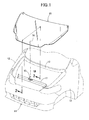
- FIG. 1 is a perspective view of a front portion of a vehicle body of an automobile
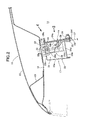
- FIG. 2 is a sectional view taken along a line 2-2 in FIG. 1
- FIG. 3 is a view seen from a direction of an arrow 3 in FIG. 2
- FIG. 4 is a view seen from a direction of an arrow 4 in FIG. 2
- FIG. 5 is an operation explanatory view at collision of a front part of the automobile.
- FIGS. 1 to 5 a description is given of an embodiment of the present invention based on FIGS. 1 to 5 .
- a front-rear direction and a right-left direction are defined with respect to an occupant sitting on a driver's seat.
- an engine room 14 surrounded by a front bumper 11, right and left front fenders 12, 12, and a dashboard 13 is openably and closably covered with a front hood 15.
- a U-shaped striker 16 is fixed on a lower surface of a front portion of the front hood 15.
- a lock device 18 is provided inside a bulkhead 17 which is a frame member arranged in the engine room 14 to extend in the right-left direction. The front hood 15 is locked at a closed position by locking the striker 16 with the lock device 18.
- the front hood 15 is formed in such a manner that a hood skin 20 is overlapped with an upper surface of a hood frame 19 and is joined to the hood frame 19 at a peripheral edge portion thereof.
- a stiffener 21 is welded to an inner surface of a front portion of the front hood 15.
- a plate-shaped bracket 22 having the striker 16 fixed thereon is welded to the hood frame 19 behind the stiffener 21.
- the bulkhead 17 is formed in a quadrangular closed cross section by welding a first member 23 and a second member 24, and accommodates therein a base portion 28 of the lock device 18.
- the first member 23 is formed by a thin plate, including a front wall 23a and an upper wall 23b to have an L-shaped cross section.
- the second member 24 is formed by a thick plate, including a rear wall 24a and a lower wall 24b to have an L-shaped cross section.
- the base portion 28 is a box-shaped member with a lower face opened, including a front face 28a, a rear face 28b, an upper face 28c, and right and left side faces 28d, 28d.
- Paired attachment plates 28e, 28e protrude in the right-left direction from the upper face 28c, while an attachment plate 28f protrudes downward from the rear face 28b.
- a lower end of a hook 30 engageable with the striker 16 is pivotally supported to be swingable to the right and left by a fulcrum pin 29 provided between the front face 28a and the rear face 28b.
- a slit 28g extending in the front-rear direction is formed in the front face 28a, the upper face 28c, and the rear face 28b. The slit 28g allows the striker 16 to enter into the base portion 28.
- An opening 23c in a square shape is formed in the upper wall 23b of the first member 23, and a first cut-out 24c and a second cut-out 24d which are mutually continuous are formed in the rear wall 24a and the lower wall 24b of the second member 24.
- the base portion 28 is inserted into the bulkhead 17 through the opening 23c of the upper wall 23b.
- the paired attachment plates 28e, 28e continuous with the upper face 28c are fastened to the upper wall 23b of the first member 23 with bolts 33, 33 and nuts 34, 34.
- the rear wall 24a of the second member 24 there are formed: two slits 24e, 24e respectively extending upward from right and left side edges of the first cut-out 24c; and a bracket 24f extending downward from an upper edge of the first cut-out 24c to below the lower wall 24b of the second member 24.
- the attachment plate 28f protruding downward from the rear face 28b of the base portion 28 is fastened to the bracket 24f with a bolt 35 and a nut 36.
- a lower half portion of the rear face 28b of the base portion 28 faces the first cut-out 24c in the rear wall 24a of the second member 24, and the opened lower face of the base portion 28 faces the second cut-out 24d in the lower wall 24b of the second member 24.
- connection means such as a cable 37 connects the hook 30 and an unillustrated unlocking lever provided in a vehicle cabin.
- the upper wall 23b of the first member 23 of the bulkhead 17 supporting the attachment plates 28e, 28e of the upper face 28c of the base portion 28 is formed by a thin plate, and the front wall 23a, of the first member 23, continuous with the upper wall 23b is also formed of a thin plate.
- the upper wall 23b and the front wall 23a are easily deformed, and the base portion 28 moves downward while turning in such a manner that the lower portion of the base portion 28 turns rearward. At this time, the deformation can be accelerated while the rigidity of the upper wall 23b is reduced due to the opening 23c formed in the thin-plate upper wall 23b for inserting the base portion 28 therein.
- the attachment plate 28f provided to the rear face 28b of the base portion 28 is fixed onto the bracket 24f of the rear wall 24a of the second member 24, and the bracket 24f is formed by a thick plate. Since the bracket 24f is made brittle due to the first cut-out 24c and the paired slits 24e, 24e, the rear wall 24a pushed by the rear face 28b of the base portion 28 is easily bent along a line connecting upper ends of the paired slits 24e, 24e. The rear face 28b of the base portion 28 passes through the first cut-out 24c in the rear wall 24a, and thereby the base portion 28 can turn in such a manner that the rear face 28b turns rearward.
- the base portion 28 moves downward due to deformation of the upper wall 23b and the front wall 23a of the first member 23 and an upper portion of the rear wall 24a of the second member 24, the lower face of the base portion 28 can pass downward through the second cut-out 24d in the lower wall 24b of the second member 24.
- the base portion 28 can move downward without interfering with the lower wall 24b.
- the base portion 28 of the lock device 18 configured to lock the striker 16 of the front hood 15 can move both rearward and downward.
- rearward and downward impact absorption strokes can be increased to enhance the impact absorption performance.
- the magnitude of the load at which the base portion 28 of the lock device 18 moves at the collision is constant without being influenced by a bolt tightening torque, and the load can be set optionally according to the plate thickness or the shape of the first and second members 23, 24 of the bulkhead 17.
- the front portion of the front hood 15 is always moved rearward or downward in a stroke at an optimum load, so that the effect of absorbing the collision energy can be enhanced.
- the base portion 28 can reliably receive the impact of closing the front hood 15.
- the frame member of the present invention is not limited to the bulkhead 17 in the embodiment.
- the first member 23 of the bulkhead 17 is formed by a thin plate, while the second member 24 is formed by a thick plate.
- the plate thicknesses thereof, however, are relative to each other. What is required is that the first member 23 has a smaller plate thickness than the second member 24 does.
Landscapes
- Engineering & Computer Science (AREA)
- Mechanical Engineering (AREA)
- Superstructure Of Vehicle (AREA)
Abstract
Description
- The present invention relates to a hood lock device in which a striker provided in a protruding manner downward from a front portion of a front hood is locked with a lock device provided inside a frame member of a vehicle body, the front hood openably and closably covering an engine room.
- At a collision of a front hood of an automobile with a pedestrian, if the front hood collapses in a large stroke to absorb collision energy, impact imposed on the pedestrian can be reduced. However, since a striker of the front hood is locked with a lock device, which is provided to a frame member such as a bulkhead, in order that the front hood be locked at a closed position, movement of the front hood is hindered by this portion. This causes a problem that a sufficient impact absorption stroke cannot be ensured.
- Hence, the following hood lock device is publicly known by Japanese Patent Application Laid-open No.
2009-255635 - In addition, the front hood receives the collision load not only from the front but also from the above. In this regard, the following structure is publicly known by Japanese Patent Application Laid-open No.
2009-57708 - Incidentally, the inventions described in Japanese Patent Application Laid-open Nos.
2009-255635 2009-57708 - The present invention has been made in view of the aforementioned circumstances, and an object thereof is to ensure an impact absorption stroke at collision of a front portion of an automobile by moving a front portion of a front hood at a desirable load.
- In order to achieve the object, according to the invention described in
claim 1, there is provided a hood lock device in which a striker provided in a protruding manner downward from a front portion of a front hood is locked with a lock device provided inside a frame member of a vehicle body, the front hood openably and closably covering an engine room, characterized in that the frame member accommodating a base portion of the lock device is a member having a quadrangular closed cross section formed by joining a first member and a second member, the first member being formed of a thin plate having an L-shaped cross section including a front wall and an upper wall, the second member being formed of a thick plate having an L-shaped cross section including a rear wall and a lower wall, and an upper face of the base portion is fixed to the upper wall, and a first cut-out allowing a rear face of the base portion to pass therethrough is formed in the rear wall facing the rear face of the base portion. - According to the configuration of
claim 1, when a collision load of a frontal collision imposed on the front hood is transmitted through the striker from the front or the above to the upper portion of the lock device provided inside the frame member, the upper wall of the thin-plate first member of the frame member to which the base portion of the lock device is fixed and the front wall continuous with the upper wall are deformed to allow the base portion to move rearward and downward. Thereby, an impact absorption stroke for absorbing collision energy is ensured. At this time, if the rear face of the base portion interferes with the rear wall of the thick-plate second member, the base portion is hindered from moving rearward. However, the rear face of the base portion passes through the first cut-out in the rear wall, and thereby a large rearward impact absorption stroke is ensured. - Further, according to the invention described in
claim 2, in addition to the configuration ofclaim 1, there is provided the hood lock device, wherein a second cut-out allowing a lower face of the base portion to pass therethrough is formed in the lower wall in such a manner as to be continuous with the first cut-out, the lower wall facing the lower face of the base portion. - According to the configuration of
claim 2, the second cut-out allowing the lower face of the base portion to pass therethrough is formed in the lower wall of the thick-plate second member in such a manner as to be continuous with the first cut-out, the lower wall facing the lower face of the base portion. Accordingly, when the thin-plate first member is deformed downward to allow the base portion to move downward, the lower face of the base portion does not interfere with the lower wall of the thick-plate second member, and thus the movement of the base portion is not hindered. A large downward impact absorption stroke of the base portion is thus ensured. - Further, according to the invention described in
claim 3, in addition to the configuration ofclaim - According to the configuration of
claim 3, the rear wall of the thick-plate second member includes the paired slits extending upward along the right and left side faces of the base portion from the upper edge of the first cut-out. Thus, when the collision load is inputted to the base portion from the front hood through the striker, the rear wall made brittle due to the paired slits is bent, and thereby the base portion can be reliably moved rearward. - Further, according to the invention described in
claim 4, in addition to the configuration of any one ofclaims 1 to 3, there is provided the hood lock device, wherein the rear face of the base portion is fixed to the rear wall. - According to the configuration of
claim 4, the rear face of the base portion is fixed to the rear wall of the thick-plate second member of the frame member. Accordingly, it is possible to prevent downward movement of the base portion due to downward impact at the time of strongly closing the front hood. - Further, according to the invention described in
claim 5, in addition to the configuration ofclaim 4, there is provided the hood lock device, wherein an opening for inserting the base portion therein is formed in the upper wall of the frame member. - According to the configuration of
claim 5, the opening for inserting the base portion therein is formed in the upper wall of the frame member. Accordingly, when the collision load is inputted to the base portion from the front hood through the striker, the upper wall made brittle due to the opening is efficiently deformed, and thereby the base portion can be reliably moved rearward and downward. - The above and other objects, characteristics and advantages of the present invention will be clear from detailed descriptions of the preferred embodiment which will be provided below while referring to the attached drawings.
-
FIG. 1 is a perspective view of a front portion of a vehicle body of an automobile;FIG. 2 is a sectional view taken along a line 2-2 inFIG. 1 ;FIG. 3 is a view seen from a direction of anarrow 3 inFIG. 2 ;FIG. 4 is a view seen from a direction of anarrow 4 inFIG. 2 ; andFIG. 5 is an operation explanatory view at collision of a front part of the automobile. - Hereinbelow, a description is given of an embodiment of the present invention based on
FIGS. 1 to 5 . Here, in the specification, a front-rear direction and a right-left direction are defined with respect to an occupant sitting on a driver's seat. - As shown in
FIG. 1 , anengine room 14 surrounded by afront bumper 11, right and leftfront fenders dashboard 13 is openably and closably covered with afront hood 15. A U-shapedstriker 16 is fixed on a lower surface of a front portion of thefront hood 15. Alock device 18 is provided inside abulkhead 17 which is a frame member arranged in theengine room 14 to extend in the right-left direction. Thefront hood 15 is locked at a closed position by locking thestriker 16 with thelock device 18. - As shown in
FIGS. 2 to 4 , thefront hood 15 is formed in such a manner that ahood skin 20 is overlapped with an upper surface of ahood frame 19 and is joined to thehood frame 19 at a peripheral edge portion thereof. Astiffener 21 is welded to an inner surface of a front portion of thefront hood 15. A plate-shaped bracket 22 having thestriker 16 fixed thereon is welded to thehood frame 19 behind thestiffener 21. - The
bulkhead 17 is formed in a quadrangular closed cross section by welding afirst member 23 and asecond member 24, and accommodates therein abase portion 28 of thelock device 18. Thefirst member 23 is formed by a thin plate, including afront wall 23a and anupper wall 23b to have an L-shaped cross section. Thesecond member 24 is formed by a thick plate, including arear wall 24a and alower wall 24b to have an L-shaped cross section. - The
base portion 28 is a box-shaped member with a lower face opened, including afront face 28a, arear face 28b, anupper face 28c, and right and left side faces 28d, 28d.Paired attachment plates upper face 28c, while anattachment plate 28f protrudes downward from therear face 28b. A lower end of ahook 30 engageable with thestriker 16 is pivotally supported to be swingable to the right and left by afulcrum pin 29 provided between thefront face 28a and therear face 28b. Aslit 28g extending in the front-rear direction is formed in thefront face 28a, theupper face 28c, and therear face 28b. Theslit 28g allows thestriker 16 to enter into thebase portion 28. - An opening 23c in a square shape is formed in the
upper wall 23b of thefirst member 23, and a first cut-out 24c and a second cut-out 24d which are mutually continuous are formed in therear wall 24a and thelower wall 24b of thesecond member 24. Thebase portion 28 is inserted into thebulkhead 17 through the opening 23c of theupper wall 23b. The pairedattachment plates upper face 28c are fastened to theupper wall 23b of thefirst member 23 withbolts nuts - In the
rear wall 24a of thesecond member 24, there are formed: twoslits bracket 24f extending downward from an upper edge of the first cut-out 24c to below thelower wall 24b of thesecond member 24. Theattachment plate 28f protruding downward from therear face 28b of thebase portion 28 is fastened to thebracket 24f with abolt 35 and anut 36. In this state, a lower half portion of therear face 28b of thebase portion 28 faces the first cut-out 24c in therear wall 24a of thesecond member 24, and the opened lower face of thebase portion 28 faces the second cut-out 24d in thelower wall 24b of thesecond member 24. - When the
striker 16 provided on the lower surface of thefront hood 15 is engaged with thehook 30 of thelock device 18 with thefront hood 15 closed, thefront hood 15 is thereby locked at a closed position. For unlocking thelock device 18, connection means such as acable 37 connects thehook 30 and an unillustrated unlocking lever provided in a vehicle cabin. - Next, a description of operations of the embodiment of the present invention having the above-described configuration will be given.
- Suppose a case where a frontal collision with an obstacle such as a pedestrian occurs on a vehicle, and a rearward collision load is inputted from the femurs and the waist to a front end of the
front hood 15. In this case, as shown inFIG. 5 , the front portion of thefront hood 15 buckles in the front-rear direction, so that collision energy is absorbed. At this time, thestriker 16 provided on the lower surface of the front portion of thefront hood 15 moves rearward, and the movement is transmitted to thebase portion 28 through thehook 30 of thelock device 18. - The
upper wall 23b of thefirst member 23 of thebulkhead 17 supporting theattachment plates upper face 28c of thebase portion 28 is formed by a thin plate, and thefront wall 23a, of thefirst member 23, continuous with theupper wall 23b is also formed of a thin plate. Thus, theupper wall 23b and thefront wall 23a are easily deformed, and thebase portion 28 moves downward while turning in such a manner that the lower portion of thebase portion 28 turns rearward. At this time, the deformation can be accelerated while the rigidity of theupper wall 23b is reduced due to theopening 23c formed in the thin-plateupper wall 23b for inserting thebase portion 28 therein. - The
attachment plate 28f provided to therear face 28b of thebase portion 28 is fixed onto thebracket 24f of therear wall 24a of thesecond member 24, and thebracket 24f is formed by a thick plate. Since thebracket 24f is made brittle due to the first cut-out 24c and the pairedslits rear wall 24a pushed by therear face 28b of thebase portion 28 is easily bent along a line connecting upper ends of the pairedslits rear face 28b of thebase portion 28 passes through the first cut-out 24c in therear wall 24a, and thereby thebase portion 28 can turn in such a manner that therear face 28b turns rearward. - In addition, even though the
base portion 28 moves downward due to deformation of theupper wall 23b and thefront wall 23a of thefirst member 23 and an upper portion of therear wall 24a of thesecond member 24, the lower face of thebase portion 28 can pass downward through the second cut-out 24d in thelower wall 24b of thesecond member 24. Thus, thebase portion 28 can move downward without interfering with thelower wall 24b. - As described above, when a collision load is inputted from the front or the above to the
front hood 15 due to a frontal collision with a pedestrian, thebase portion 28 of thelock device 18 configured to lock thestriker 16 of thefront hood 15 can move both rearward and downward. Thus, rearward and downward impact absorption strokes can be increased to enhance the impact absorption performance. - Moreover, the magnitude of the load at which the
base portion 28 of thelock device 18 moves at the collision is constant without being influenced by a bolt tightening torque, and the load can be set optionally according to the plate thickness or the shape of the first andsecond members bulkhead 17. Thus, the front portion of thefront hood 15 is always moved rearward or downward in a stroke at an optimum load, so that the effect of absorbing the collision energy can be enhanced. - Further, when the
front hood 15 is closed strongly, a downward load is inputted to thebase portion 28 from thestriker 16 through thehook 30. Since theattachment plate 28f of therear face 28b of thebase portion 28 is fixed onto therear wall 24a of the thick-platesecond member 24 with thebolt 35 and thenut 36, thebase portion 28 can reliably receive the impact of closing thefront hood 15. - An embodiment of the present invention has been described above, but various design modifications can be made without departing from the gist of the present invention.
- For example, the frame member of the present invention is not limited to the
bulkhead 17 in the embodiment. - In the embodiment, the
first member 23 of thebulkhead 17 is formed by a thin plate, while thesecond member 24 is formed by a thick plate. The plate thicknesses thereof, however, are relative to each other. What is required is that thefirst member 23 has a smaller plate thickness than thesecond member 24 does. - When a collision load of a frontal collision imposed on a front hood is transmitted through a striker (16) from the front or the above to an upper portion of a lock device (18) provided inside a frame member (17), an upper wall (23b) of a thin-plate first member (23) of the frame member (17) to which a base portion (28) of the lock device (18) is fixed and a front wall (23a) continuous with the upper wall (23b) are deformed to allow the base portion (28) to move rearward and downward. Thereby, an impact absorption stroke for absorbing collision energy is ensured. At this time, if a rear face (28b) of the base portion (28) interferes with a rear wall (24a) of a thick-plate second member (24), the base portion (28) is hindered from moving rearward. However, the rear face (28b) of the base portion (28) passes through a first cut-out (24c) in the rear wall (24a), and thereby a rearward impact absorption stroke is ensured. Accordingly, it is possible to ensure an impact absorption stroke at collision of a front portion of an automobile by moving a front portion of a front hood at a desirable load.
Claims (5)
- A hood lock device in which a striker (16) provided in a protruding manner downward from a front portion of a front hood (15) is locked with a lock device (18) provided inside a frame member (17) of a vehicle body, the front hood (15) openably and closably covering an engine room (14),
characterized in that
the frame member (17) accommodating a base portion (28) of the lock device (18) is a member having a quadrangular closed cross section formed by joining a first member (23) and a second member (24), the first member (23) being formed of a thin plate having an L-shaped cross section including a front wall (23a) and an upper wall (23b), the second member (24) being formed of a thick plate having an L-shaped cross section including a rear wall (24a) and a lower wall (24b), and
an upper face (28c) of the base portion (28) is fixed to the upper wall (23b), and a first cut-out (24c) allowing a rear face (28b) of the base portion (28) to pass therethrough is formed in the rear wall (24a) facing the rear face (28b) of the base portion (28). - The hood lock device according to claim 1, wherein a second cut-out (24d) allowing a lower face of the base portion (28) to pass therethrough is formed in the lower wall (24b) in such a manner as to be continuous with the first cut-out (24c), the lower wall (24b) facing the lower face of the base portion (28).
- The hood lock device according to claim 1 or 2, wherein the rear wall (24a) comprises paired slits (24e) extending upward along right and left side faces (28d) of the base portion (28) from an upper edge of the first cut-out (24c).
- The hood lock device according to any one of claims 1 to 3, wherein the rear face (28b) of the base portion (28) is fixed to the rear wall (24a).
- The hood lock device according to claim 4, wherein an opening (23c) for inserting the base portion (28) therein is formed in the upper wall (23b) of the frame member (17).
Applications Claiming Priority (1)
| Application Number | Priority Date | Filing Date | Title |
|---|---|---|---|
| JP2011017673A JP5254379B2 (en) | 2011-01-31 | 2011-01-31 | Food lock device |
Publications (2)
| Publication Number | Publication Date |
|---|---|
| EP2481646A1 true EP2481646A1 (en) | 2012-08-01 |
| EP2481646B1 EP2481646B1 (en) | 2013-04-10 |
Family
ID=45507593
Family Applications (1)
| Application Number | Title | Priority Date | Filing Date |
|---|---|---|---|
| EP20120151896 Not-in-force EP2481646B1 (en) | 2011-01-31 | 2012-01-20 | Hood lock device |
Country Status (2)
| Country | Link |
|---|---|
| EP (1) | EP2481646B1 (en) |
| JP (1) | JP5254379B2 (en) |
Cited By (1)
| Publication number | Priority date | Publication date | Assignee | Title |
|---|---|---|---|---|
| GB2510668A (en) * | 2012-11-26 | 2014-08-13 | Gm Global Tech Operations Inc | Hollow cross member for vehicle with receptacle for bonnet lock |
Families Citing this family (1)
| Publication number | Priority date | Publication date | Assignee | Title |
|---|---|---|---|---|
| JP6115356B2 (en) * | 2013-06-28 | 2017-04-19 | スズキ株式会社 | Hood latch fixing structure |
Citations (5)
| Publication number | Priority date | Publication date | Assignee | Title |
|---|---|---|---|---|
| EP1506907A1 (en) * | 2003-08-11 | 2005-02-16 | Compagnie Plastic Omnium | Transverse beam of a frontal module of a vehicle, frontal module and radiator support comprising such a transverse beam |
| US20050253419A1 (en) * | 2004-05-17 | 2005-11-17 | Hyundai Mobis Co., Ltd. | Structure for mounting horizontal hood latch to upper panel of front-end module of automobile |
| DE102006046817A1 (en) * | 2006-10-02 | 2008-04-03 | Audi Ag | Structural front end for motor vehicle, includes first and second lateral supports rigidly joined to upper and lower assembly supports |
| JP2009057708A (en) | 2007-08-30 | 2009-03-19 | Toyota Motor Corp | Hood lock structure |
| JP2009255635A (en) | 2008-04-14 | 2009-11-05 | Honda Motor Co Ltd | Hood lock device |
Family Cites Families (3)
| Publication number | Priority date | Publication date | Assignee | Title |
|---|---|---|---|---|
| JP4107103B2 (en) * | 2003-02-21 | 2008-06-25 | トヨタ自動車株式会社 | Lift up hood |
| JP4345412B2 (en) * | 2003-09-03 | 2009-10-14 | マツダ株式会社 | Front body structure of the vehicle |
| JP2009208729A (en) * | 2008-03-06 | 2009-09-17 | Toyota Motor Corp | Hood lock part structure |
-
2011
- 2011-01-31 JP JP2011017673A patent/JP5254379B2/en not_active Expired - Fee Related
-
2012
- 2012-01-20 EP EP20120151896 patent/EP2481646B1/en not_active Not-in-force
Patent Citations (5)
| Publication number | Priority date | Publication date | Assignee | Title |
|---|---|---|---|---|
| EP1506907A1 (en) * | 2003-08-11 | 2005-02-16 | Compagnie Plastic Omnium | Transverse beam of a frontal module of a vehicle, frontal module and radiator support comprising such a transverse beam |
| US20050253419A1 (en) * | 2004-05-17 | 2005-11-17 | Hyundai Mobis Co., Ltd. | Structure for mounting horizontal hood latch to upper panel of front-end module of automobile |
| DE102006046817A1 (en) * | 2006-10-02 | 2008-04-03 | Audi Ag | Structural front end for motor vehicle, includes first and second lateral supports rigidly joined to upper and lower assembly supports |
| JP2009057708A (en) | 2007-08-30 | 2009-03-19 | Toyota Motor Corp | Hood lock structure |
| JP2009255635A (en) | 2008-04-14 | 2009-11-05 | Honda Motor Co Ltd | Hood lock device |
Cited By (1)
| Publication number | Priority date | Publication date | Assignee | Title |
|---|---|---|---|---|
| GB2510668A (en) * | 2012-11-26 | 2014-08-13 | Gm Global Tech Operations Inc | Hollow cross member for vehicle with receptacle for bonnet lock |
Also Published As
| Publication number | Publication date |
|---|---|
| JP5254379B2 (en) | 2013-08-07 |
| JP2012158212A (en) | 2012-08-23 |
| EP2481646B1 (en) | 2013-04-10 |
Similar Documents
| Publication | Publication Date | Title |
|---|---|---|
| EP2481645A1 (en) | Hood lock device | |
| US8141937B2 (en) | Vehicle body structure | |
| JP6020944B2 (en) | Auto body structure | |
| US10160418B2 (en) | Front vehicle-body structure | |
| US8251439B2 (en) | Vehicle body | |
| JP5722056B2 (en) | Food lock device | |
| JP5135036B2 (en) | Food lock device | |
| EP2481646B1 (en) | Hood lock device | |
| US10676132B2 (en) | Suspension member | |
| FR2989104A1 (en) | REINFORCING LOCK FOR AN AUTOMOTIVE VEHICLE DOOR, DOOR EQUIPPED WITH SUCH A REINFORCEMENT AND VEHICLE EQUIPPED WITH SUCH DOOR. | |
| JP4973391B2 (en) | Hood lock structure | |
| US10894565B2 (en) | Vehicle front structure having hood lock cable routing structure | |
| WO2016088222A1 (en) | Upper door latch device for vehicle | |
| JP5251262B2 (en) | Vehicle hood structure | |
| JP6338887B2 (en) | Vehicle collision energy absorption structure | |
| JP2011225116A (en) | Vehicle front part structure | |
| JP6670498B2 (en) | Body side structure | |
| JP6108308B2 (en) | Vehicle seat | |
| JP7073284B2 (en) | Assist grip | |
| JP2005138603A (en) | Body front structure | |
| JP6070622B2 (en) | Car door structure | |
| CN114718398B (en) | Vehicle door stopper installation part structure | |
| JP6451384B2 (en) | Vehicle door structure | |
| JP2014169035A (en) | Car body structure of automobile | |
| JP4773203B2 (en) | Seat belt anchor locking device |
Legal Events
| Date | Code | Title | Description |
|---|---|---|---|
| PUAI | Public reference made under article 153(3) epc to a published international application that has entered the european phase |
Free format text: ORIGINAL CODE: 0009012 |
|
| 17P | Request for examination filed |
Effective date: 20120120 |
|
| AK | Designated contracting states |
Kind code of ref document: A1 Designated state(s): AL AT BE BG CH CY CZ DE DK EE ES FI FR GB GR HR HU IE IS IT LI LT LU LV MC MK MT NL NO PL PT RO RS SE SI SK SM TR |
|
| AX | Request for extension of the european patent |
Extension state: BA ME |
|
| GRAP | Despatch of communication of intention to grant a patent |
Free format text: ORIGINAL CODE: EPIDOSNIGR1 |
|
| RIC1 | Information provided on ipc code assigned before grant |
Ipc: B60R 21/34 20110101AFI20121105BHEP |
|
| GRAS | Grant fee paid |
Free format text: ORIGINAL CODE: EPIDOSNIGR3 |
|
| GRAA | (expected) grant |
Free format text: ORIGINAL CODE: 0009210 |
|
| AK | Designated contracting states |
Kind code of ref document: B1 Designated state(s): AL AT BE BG CH CY CZ DE DK EE ES FI FR GB GR HR HU IE IS IT LI LT LU LV MC MK MT NL NO PL PT RO RS SE SI SK SM TR |
|
| REG | Reference to a national code |
Ref country code: GB Ref legal event code: FG4D |
|
| REG | Reference to a national code |
Ref country code: AT Ref legal event code: REF Ref document number: 605796 Country of ref document: AT Kind code of ref document: T Effective date: 20130415 Ref country code: CH Ref legal event code: EP |
|
| REG | Reference to a national code |
Ref country code: IE Ref legal event code: FG4D |
|
| REG | Reference to a national code |
Ref country code: DE Ref legal event code: R096 Ref document number: 602012000022 Country of ref document: DE Effective date: 20130606 |
|
| PG25 | Lapsed in a contracting state [announced via postgrant information from national office to epo] |
Ref country code: SI Free format text: LAPSE BECAUSE OF FAILURE TO SUBMIT A TRANSLATION OF THE DESCRIPTION OR TO PAY THE FEE WITHIN THE PRESCRIBED TIME-LIMIT Effective date: 20130410 |
|
| REG | Reference to a national code |
Ref country code: AT Ref legal event code: MK05 Ref document number: 605796 Country of ref document: AT Kind code of ref document: T Effective date: 20130410 |
|
| REG | Reference to a national code |
Ref country code: NL Ref legal event code: VDEP Effective date: 20130410 Ref country code: LT Ref legal event code: MG4D |
|
| PG25 | Lapsed in a contracting state [announced via postgrant information from national office to epo] |
Ref country code: LT Free format text: LAPSE BECAUSE OF FAILURE TO SUBMIT A TRANSLATION OF THE DESCRIPTION OR TO PAY THE FEE WITHIN THE PRESCRIBED TIME-LIMIT Effective date: 20130410 Ref country code: IS Free format text: LAPSE BECAUSE OF FAILURE TO SUBMIT A TRANSLATION OF THE DESCRIPTION OR TO PAY THE FEE WITHIN THE PRESCRIBED TIME-LIMIT Effective date: 20130810 Ref country code: BE Free format text: LAPSE BECAUSE OF FAILURE TO SUBMIT A TRANSLATION OF THE DESCRIPTION OR TO PAY THE FEE WITHIN THE PRESCRIBED TIME-LIMIT Effective date: 20130410 Ref country code: ES Free format text: LAPSE BECAUSE OF FAILURE TO SUBMIT A TRANSLATION OF THE DESCRIPTION OR TO PAY THE FEE WITHIN THE PRESCRIBED TIME-LIMIT Effective date: 20130721 Ref country code: NO Free format text: LAPSE BECAUSE OF FAILURE TO SUBMIT A TRANSLATION OF THE DESCRIPTION OR TO PAY THE FEE WITHIN THE PRESCRIBED TIME-LIMIT Effective date: 20130710 Ref country code: AT Free format text: LAPSE BECAUSE OF FAILURE TO SUBMIT A TRANSLATION OF THE DESCRIPTION OR TO PAY THE FEE WITHIN THE PRESCRIBED TIME-LIMIT Effective date: 20130410 Ref country code: GR Free format text: LAPSE BECAUSE OF FAILURE TO SUBMIT A TRANSLATION OF THE DESCRIPTION OR TO PAY THE FEE WITHIN THE PRESCRIBED TIME-LIMIT Effective date: 20130711 Ref country code: PT Free format text: LAPSE BECAUSE OF FAILURE TO SUBMIT A TRANSLATION OF THE DESCRIPTION OR TO PAY THE FEE WITHIN THE PRESCRIBED TIME-LIMIT Effective date: 20130812 Ref country code: FI Free format text: LAPSE BECAUSE OF FAILURE TO SUBMIT A TRANSLATION OF THE DESCRIPTION OR TO PAY THE FEE WITHIN THE PRESCRIBED TIME-LIMIT Effective date: 20130410 Ref country code: SE Free format text: LAPSE BECAUSE OF FAILURE TO SUBMIT A TRANSLATION OF THE DESCRIPTION OR TO PAY THE FEE WITHIN THE PRESCRIBED TIME-LIMIT Effective date: 20130410 Ref country code: NL Free format text: LAPSE BECAUSE OF FAILURE TO SUBMIT A TRANSLATION OF THE DESCRIPTION OR TO PAY THE FEE WITHIN THE PRESCRIBED TIME-LIMIT Effective date: 20130410 |
|
| PG25 | Lapsed in a contracting state [announced via postgrant information from national office to epo] |
Ref country code: PL Free format text: LAPSE BECAUSE OF FAILURE TO SUBMIT A TRANSLATION OF THE DESCRIPTION OR TO PAY THE FEE WITHIN THE PRESCRIBED TIME-LIMIT Effective date: 20130410 Ref country code: HR Free format text: LAPSE BECAUSE OF FAILURE TO SUBMIT A TRANSLATION OF THE DESCRIPTION OR TO PAY THE FEE WITHIN THE PRESCRIBED TIME-LIMIT Effective date: 20130410 Ref country code: CY Free format text: LAPSE BECAUSE OF FAILURE TO SUBMIT A TRANSLATION OF THE DESCRIPTION OR TO PAY THE FEE WITHIN THE PRESCRIBED TIME-LIMIT Effective date: 20130410 Ref country code: RS Free format text: LAPSE BECAUSE OF FAILURE TO SUBMIT A TRANSLATION OF THE DESCRIPTION OR TO PAY THE FEE WITHIN THE PRESCRIBED TIME-LIMIT Effective date: 20130410 Ref country code: LV Free format text: LAPSE BECAUSE OF FAILURE TO SUBMIT A TRANSLATION OF THE DESCRIPTION OR TO PAY THE FEE WITHIN THE PRESCRIBED TIME-LIMIT Effective date: 20130410 Ref country code: BG Free format text: LAPSE BECAUSE OF FAILURE TO SUBMIT A TRANSLATION OF THE DESCRIPTION OR TO PAY THE FEE WITHIN THE PRESCRIBED TIME-LIMIT Effective date: 20130710 |
|
| PG25 | Lapsed in a contracting state [announced via postgrant information from national office to epo] |
Ref country code: EE Free format text: LAPSE BECAUSE OF FAILURE TO SUBMIT A TRANSLATION OF THE DESCRIPTION OR TO PAY THE FEE WITHIN THE PRESCRIBED TIME-LIMIT Effective date: 20130410 Ref country code: CZ Free format text: LAPSE BECAUSE OF FAILURE TO SUBMIT A TRANSLATION OF THE DESCRIPTION OR TO PAY THE FEE WITHIN THE PRESCRIBED TIME-LIMIT Effective date: 20130410 Ref country code: DK Free format text: LAPSE BECAUSE OF FAILURE TO SUBMIT A TRANSLATION OF THE DESCRIPTION OR TO PAY THE FEE WITHIN THE PRESCRIBED TIME-LIMIT Effective date: 20130410 Ref country code: SK Free format text: LAPSE BECAUSE OF FAILURE TO SUBMIT A TRANSLATION OF THE DESCRIPTION OR TO PAY THE FEE WITHIN THE PRESCRIBED TIME-LIMIT Effective date: 20130410 |
|
| PLBE | No opposition filed within time limit |
Free format text: ORIGINAL CODE: 0009261 |
|
| STAA | Information on the status of an ep patent application or granted ep patent |
Free format text: STATUS: NO OPPOSITION FILED WITHIN TIME LIMIT |
|
| PG25 | Lapsed in a contracting state [announced via postgrant information from national office to epo] |
Ref country code: IT Free format text: LAPSE BECAUSE OF FAILURE TO SUBMIT A TRANSLATION OF THE DESCRIPTION OR TO PAY THE FEE WITHIN THE PRESCRIBED TIME-LIMIT Effective date: 20130410 Ref country code: RO Free format text: LAPSE BECAUSE OF FAILURE TO SUBMIT A TRANSLATION OF THE DESCRIPTION OR TO PAY THE FEE WITHIN THE PRESCRIBED TIME-LIMIT Effective date: 20130410 |
|
| 26N | No opposition filed |
Effective date: 20140113 |
|
| REG | Reference to a national code |
Ref country code: DE Ref legal event code: R097 Ref document number: 602012000022 Country of ref document: DE Effective date: 20140113 |
|
| PG25 | Lapsed in a contracting state [announced via postgrant information from national office to epo] |
Ref country code: LU Free format text: LAPSE BECAUSE OF FAILURE TO SUBMIT A TRANSLATION OF THE DESCRIPTION OR TO PAY THE FEE WITHIN THE PRESCRIBED TIME-LIMIT Effective date: 20140120 |
|
| REG | Reference to a national code |
Ref country code: IE Ref legal event code: MM4A |
|
| REG | Reference to a national code |
Ref country code: DE Ref legal event code: R084 Ref document number: 602012000022 Country of ref document: DE |
|
| REG | Reference to a national code |
Ref country code: DE Ref legal event code: R084 Ref document number: 602012000022 Country of ref document: DE Effective date: 20141120 |
|
| REG | Reference to a national code |
Ref country code: FR Ref legal event code: PLFP Year of fee payment: 4 |
|
| PG25 | Lapsed in a contracting state [announced via postgrant information from national office to epo] |
Ref country code: IE Free format text: LAPSE BECAUSE OF NON-PAYMENT OF DUE FEES Effective date: 20140120 |
|
| PG25 | Lapsed in a contracting state [announced via postgrant information from national office to epo] |
Ref country code: MC Free format text: LAPSE BECAUSE OF FAILURE TO SUBMIT A TRANSLATION OF THE DESCRIPTION OR TO PAY THE FEE WITHIN THE PRESCRIBED TIME-LIMIT Effective date: 20130410 |
|
| PGFP | Annual fee paid to national office [announced via postgrant information from national office to epo] |
Ref country code: DE Payment date: 20150113 Year of fee payment: 4 |
|
| PGFP | Annual fee paid to national office [announced via postgrant information from national office to epo] |
Ref country code: FR Payment date: 20150108 Year of fee payment: 4 |
|
| REG | Reference to a national code |
Ref country code: CH Ref legal event code: PL |
|
| PG25 | Lapsed in a contracting state [announced via postgrant information from national office to epo] |
Ref country code: CH Free format text: LAPSE BECAUSE OF NON-PAYMENT OF DUE FEES Effective date: 20150131 Ref country code: LI Free format text: LAPSE BECAUSE OF NON-PAYMENT OF DUE FEES Effective date: 20150131 |
|
| PG25 | Lapsed in a contracting state [announced via postgrant information from national office to epo] |
Ref country code: MT Free format text: LAPSE BECAUSE OF FAILURE TO SUBMIT A TRANSLATION OF THE DESCRIPTION OR TO PAY THE FEE WITHIN THE PRESCRIBED TIME-LIMIT Effective date: 20130410 |
|
| PG25 | Lapsed in a contracting state [announced via postgrant information from national office to epo] |
Ref country code: SM Free format text: LAPSE BECAUSE OF FAILURE TO SUBMIT A TRANSLATION OF THE DESCRIPTION OR TO PAY THE FEE WITHIN THE PRESCRIBED TIME-LIMIT Effective date: 20130410 |
|
| PG25 | Lapsed in a contracting state [announced via postgrant information from national office to epo] |
Ref country code: HU Free format text: LAPSE BECAUSE OF FAILURE TO SUBMIT A TRANSLATION OF THE DESCRIPTION OR TO PAY THE FEE WITHIN THE PRESCRIBED TIME-LIMIT; INVALID AB INITIO Effective date: 20120120 Ref country code: TR Free format text: LAPSE BECAUSE OF FAILURE TO SUBMIT A TRANSLATION OF THE DESCRIPTION OR TO PAY THE FEE WITHIN THE PRESCRIBED TIME-LIMIT Effective date: 20130410 |
|
| REG | Reference to a national code |
Ref country code: DE Ref legal event code: R119 Ref document number: 602012000022 Country of ref document: DE |
|
| GBPC | Gb: european patent ceased through non-payment of renewal fee |
Effective date: 20160120 |
|
| REG | Reference to a national code |
Ref country code: FR Ref legal event code: ST Effective date: 20160930 |
|
| PG25 | Lapsed in a contracting state [announced via postgrant information from national office to epo] |
Ref country code: DE Free format text: LAPSE BECAUSE OF NON-PAYMENT OF DUE FEES Effective date: 20160802 Ref country code: GB Free format text: LAPSE BECAUSE OF NON-PAYMENT OF DUE FEES Effective date: 20160120 |
|
| PG25 | Lapsed in a contracting state [announced via postgrant information from national office to epo] |
Ref country code: FR Free format text: LAPSE BECAUSE OF NON-PAYMENT OF DUE FEES Effective date: 20160201 |
|
| PG25 | Lapsed in a contracting state [announced via postgrant information from national office to epo] |
Ref country code: MK Free format text: LAPSE BECAUSE OF FAILURE TO SUBMIT A TRANSLATION OF THE DESCRIPTION OR TO PAY THE FEE WITHIN THE PRESCRIBED TIME-LIMIT Effective date: 20130410 |
|
| PG25 | Lapsed in a contracting state [announced via postgrant information from national office to epo] |
Ref country code: AL Free format text: LAPSE BECAUSE OF FAILURE TO SUBMIT A TRANSLATION OF THE DESCRIPTION OR TO PAY THE FEE WITHIN THE PRESCRIBED TIME-LIMIT Effective date: 20130410 |