EP2480430B1 - Vacuum mounted carrier for a vehicle - Google Patents
Vacuum mounted carrier for a vehicle Download PDFInfo
- Publication number
- EP2480430B1 EP2480430B1 EP10819409.3A EP10819409A EP2480430B1 EP 2480430 B1 EP2480430 B1 EP 2480430B1 EP 10819409 A EP10819409 A EP 10819409A EP 2480430 B1 EP2480430 B1 EP 2480430B1
- Authority
- EP
- European Patent Office
- Prior art keywords
- vacuum
- carrier system
- shaped
- mount
- frame
- Prior art date
- Legal status (The legal status is an assumption and is not a legal conclusion. Google has not performed a legal analysis and makes no representation as to the accuracy of the status listed.)
- Active
Links
Images




Classifications
-
- B—PERFORMING OPERATIONS; TRANSPORTING
- B60—VEHICLES IN GENERAL
- B60R—VEHICLES, VEHICLE FITTINGS, OR VEHICLE PARTS, NOT OTHERWISE PROVIDED FOR
- B60R11/00—Arrangements for holding or mounting articles, not otherwise provided for
-
- B—PERFORMING OPERATIONS; TRANSPORTING
- B60—VEHICLES IN GENERAL
- B60R—VEHICLES, VEHICLE FITTINGS, OR VEHICLE PARTS, NOT OTHERWISE PROVIDED FOR
- B60R9/00—Supplementary fittings on vehicle exterior for carrying loads, e.g. luggage, sports gear or the like
- B60R9/08—Supplementary fittings on vehicle exterior for carrying loads, e.g. luggage, sports gear or the like specially adapted for sports gear
-
- B—PERFORMING OPERATIONS; TRANSPORTING
- B60—VEHICLES IN GENERAL
- B60R—VEHICLES, VEHICLE FITTINGS, OR VEHICLE PARTS, NOT OTHERWISE PROVIDED FOR
- B60R9/00—Supplementary fittings on vehicle exterior for carrying loads, e.g. luggage, sports gear or the like
- B60R9/08—Supplementary fittings on vehicle exterior for carrying loads, e.g. luggage, sports gear or the like specially adapted for sports gear
- B60R9/10—Supplementary fittings on vehicle exterior for carrying loads, e.g. luggage, sports gear or the like specially adapted for sports gear for cycles
-
- B—PERFORMING OPERATIONS; TRANSPORTING
- B60—VEHICLES IN GENERAL
- B60R—VEHICLES, VEHICLE FITTINGS, OR VEHICLE PARTS, NOT OTHERWISE PROVIDED FOR
- B60R11/00—Arrangements for holding or mounting articles, not otherwise provided for
- B60R2011/0042—Arrangements for holding or mounting articles, not otherwise provided for characterised by mounting means
- B60R2011/0049—Arrangements for holding or mounting articles, not otherwise provided for characterised by mounting means for non integrated articles
- B60R2011/005—Connection with the vehicle part
- B60R2011/0056—Connection with the vehicle part using suction cups
Definitions
- the present invention relates to a system that detachably installs to automotive vehicles for transporting articles without compromising, but instead maintaining the integrity of a mounting surface, and more particularly, to a carrier system that detachably installs to vehicles with a vacuum assembly for transporting articles.
- Carriers or racks are commonly used with automotive vehicles to transport various recreational equipment, such as, bicycles, skis, snowboards, surfboards, and the like.
- Conventional carriers are mounted in one of these locations: to the roof, to the trunk, the rear window, to the truck bed, or to a trailer hitch.
- Either the carrier is permanently attached to the vehicle with fasteners, or removeably attached to the vehicle using brackets, straps, or latches.
- both methods have disadvantages.
- Permanently installed carriers can be expensive to purchase and install, and typically require modifications to the vehicle. In addition, they can not be removed. Detachable carriers are difficult and time-consuming to install and must be repeatedly installed and removed. Also, they are susceptible to damaging the vehicle during installation and use due to the plates and straps applied to the vehicle under tension which causes denting and scratching. If improperly installed, damage can occur to the vehicle and the articles being transported.
- a prior art carrier system is disclosed in US 2007/0216154A1 .
- This document discloses a carrier system for a vehicle, comprising:
- US4366605A discloses a security clip shaped and sized for engagement with a vehicle seam; an attachment member shaped and sized for engagement between the recreational article and the security clip; and a lock configured for securement of the attachment member to the security clip.
- an embodiment of the present disclosure generally referred to as a carrier system 10, includes a frame member 12, a mount 14 attached to the frame member 12 that is sized and shaped to couple with recreational articles, and vacuum devices 16 attached to the frame member 12 that can detachably attach to a mounting surface 17 of a vehicle.
- the carrier system 10 can couple with any recreational article, including, but not limited to, a bicycle, skis, a snowboard, a surfboard, a canoe, or a kayak.
- the frame 12 is generally a linear bar 18 with enlarged generally circular portions 20 at each end that are each sized and shaped to mate with respective vacuum devices 16. ( Fig. 3 ).
- the portions 20 can be any shape and size capable of mating with the vacuum devices 16.
- the frame 12 mates with two vacuum devices 16, such as with fasteners 13, to provide enough vacuum strength to withstand the tensions, shear, and other forces on the carrier system 10 during operation. Multiple vacuum devices 16 help stabilize the load and provide redundancy should one or more vacuum device 16 fail.
- the security member 22 acts as a theft deterrent.
- the frame 12 is constructed from a material capable of handling the loads and tensions occurring during operation of the carrier system, such as metal, fiberglass, plastic, or other suitable materials.
- the mount 14 includes an attachment member 24 that attaches to the outer face 26 of the frame 12, such as by welding, adhesive, fasteners, or other appropriate means ( Figs. 1-2 ). Extending from the attachment member 24 is a skewer assembly 28 sized and shaped to couple with front or rear fork arms 35 of a bicycle 37.
- the skewer assembly 28 includes a generally tubular housing 30 that defines a bore 32 along a center axis A-A. ( Fig. 1 ).
- Generally cylindrical protrusions 34 extend outwardly from each end of the housing 30 along the axis A-A.
- the protrusions 34 are shaped and sized to mate with the front clevises 36 of the fork arms, which first requires removal of the wheel.
- a skewer rod 36 inserts through the bore 32 and secures with a fasteners, such as a nut 38 and a cam clamp 40.
- the cam clamp 40 can be tightened or loosened to secure and release the fork.
- the mount 14 can include any other suitable arrangement that properly secures a recreational article, such as, straps, fasteners, clamps, cables, brackets, tethers, and the like.
- the mount 14 can include adaptors that accommodate various fork sizes and models, such as "Fork Up" available from Hurricane Components for 15mm or 20mm through-axle models.
- the rear wheel of the bicycle 37 can be cradled in the rack instead of the front fork so that the front wheel does not need to be removed.
- the vacuum devices 16 are similar to the device disclosed in U.S. patent publication No. 2007/0216154 .
- Each vacuum device 16 includes a vacuum pad 42 and an attached vacuum pump 44 ( Fig. 3 ).
- a housing 46 attaches to the vacuum pad 42 to enclose and secure the vacuum pump 44 to the vacuum pad 42.
- the housing is 46 shaped and sized to enclose the vacuum pump 44 while allowing for the attachment of an accessory and likewise to a surface of a vehicle.
- the vacuum pad 42 is generally a conical frustum that defines a top face 48 having threaded holes 50 to mount with the housing 46 using fasteners 52.
- the vacuum pad 42 also includes a recessed vacuum face 54 being generally parallel to the top face 48, a sloped side surface 56 extending between the top face 48 and the vacuum face 54, and a generally circumferential seating edge 58 along the perimeter of the vacuum face 54. In this arrangement, the seating edge 58 can seat with the mounting surface 17 of a vehicle to form a vacuum cavity 60.
- the vacuum pad 42 defines a channel 62 extending from the top face 48 to the vacuum face 54 and sized to mate with the vacuum pump 44.
- Release tabs 64 extend outwardly from the side surface 56.
- the release tabs 64 are generally t-shaped ribs that are shaped and sized to enhance rigidity of the pad 42 and help prevent release of the vacuum device 16 from the mounting surface 17, such as during exposure to warmer temperatures.
- the pad 42 is made from a flexible material, such as, rubber, or plastic.
- the pad 42 can comprise any material that allows the vacuum pad 42 to seat with the mounting surface 17.
- the material should not be prone to scuffing the mounting surface during installation or operation.
- the material can comprise any suitable color and may include other desirable attributes.
- the pad 42 can be a reflective or glow-in-the-dark material so that It can be seen in dark environments.
- the pump 44 includes a generally cylindrical plunger 66 and a hollow cylinder 68 that defines a chamber 70 sized and shaped to receive the plunger 66.
- the plunger 66 moves within the chamber 70 between a pressed position and a released position to create the vacuum cavity 60 between the vacuum face 54 and the mounting surface 17.
- the cylinder 68 has an opening to the chamber 70 at one end and is closed at the opposite end.
- a tube 72 extends generally perpendicularly from the closed end of the cylinder 68. The tube 72 is sized and shaped to insert into the channel 62 of the vacuum pad 42 to provide fluid communication between the cylinder chamber 70 and the vacuum cavity 60.
- the plunger 66 is sized to insert into the cylinder 68 with a sliding fit that allows the plunger 66 to move back and forth within the cylinder 68.
- a check valve 74 is positioned within the cylinder chamber 70 in communication with the chamber 70 and the tube 72 so that fluids and gases can only transfer into the tube 72 from outside of the cylinder 68. This allows the vacuum device 16 to be re-pumped without loss of remaining vacuum.
- an automatic pump can be used to increase the vacuum level of the vacuum device if it falls below a pre-determined level.
- a vacuum device in another alternate embodiment, includes a signaling component capable of indicating or sending a signal that indicates a loss of a designated amount of pressure, including, but not limited to, an audio signal, a visual signal, an electronic signal, or a wireless or Bluetooth® signal.
- a the signaling component can send a wireless signal to a wireless phone and, in conjunction with appropriate software on the phone, indicate the vacuum pressure.
- the plunger 66 is generally a rod with a push button 76 at one end, a seal 78 at the opposite end, and a biasing member 80 therebetween.
- the seal 78 is sized and shaped to seat against the inner wall of the cylinder 68.
- An indicator 82 positioned about the lower portion of the push button 76 indicates to the operator the relative amount of vacuum pressure within the vacuum cavity 60.
- the indicator 82 is a colored ring or sleeve sized and shaped to attach around the lower portion of the push button 76.
- the indicator 82 can be red, yellow or any color that is easily seen. Additionally, the indicator 82 can be a reflective or glow-in-the-dark material so that it can be seen in dark atmospheres and under water.
- the biasing member 80 extends the plunger 66 to its most extended release position. In this position, the indicator 82 is fully visible. As the pressure increases in the vacuum cavity 60, the force of the vacuum lessens the bias of the biasing member 80, and, in turn, the plunger 66 extends less from the chamber 70 and less of the indicator 82 is visible.
- the housing 46 is a generally cylindrical member with a generally rectangular base which includes a top surface 84, bottom surface 86, first side 88, second side 90, third side 92, and pump side 94 ( Fig. 3 ).
- the bottom surface 86 of the housing 46 defines housing apertures 96 for attachment to the vacuum pad 42 with fasteners.
- the top surface 84 defines attachment apertures 98 for attachment of accessories with appropriate means, such as fasteners, straps, and other suitable members.
- housing apertures 96 and attachment apertures 98 are shown on top side 84 of housing 46, those skilled in the art will recognize that housing apertures 96 and attachment apertures 98 can be located on any side 88, 90, 92, 94 of the housing 46.
- housing apertures 96 and attachment apertures 98 can be holes, slots, or any other configuration sized and shaped to accommodate different dimensions of various manufacturers' accessories.
- the housing 46 can be made from a variety of materials, including marine grade stainless steel, powder-coated aluminum, rubber or plastic.
- an operator places the vacuum face 54 of pad 42 against a mounting surface 17 of a vehicle, which creates a vacuum cavity 60 between the vacuum face 54 of the pad 42 and mounting surface 17.
- This embodiment is preferably used with a pick up truck, with the mounting surface comprising the rear window of the truck.
- the operator repeatedly pushes the plunger 44 from the released position to the pressed position to remove fluid (air, gas, and/or water) from the vacuum cavity 60, thereby, reducing the pressure below the pressure the surrounding atmospheric pressure.
- This creates a vacuum such that edge 58 and vacuum face 54 of pad 42 seat against the mounting surface 17.
- a vacuum exists whenever the pressure within the space is less than the pressure that surrounds it.
- the operator should repeatedly press the plunger 66 until the indicator 82 is no longer visible when the plunger 66 is in the released position. If at any time during operation, the indicator 82 becomes visible indicating a loss of vacuum, the operator can again repeatedly push the plunger 66 until the indicator 82 is no longer visible.
- a recreational device such as a bicycle can be attached to the mount 14.
- a recreational device such as a bicycle can be attached to the mount 14.
- the clevises of the fork arms 35 mate with the protrusions 34 and are secured by inserting and tightening a skewer rod 36. In this position, the rear bicycle wheel rests on the truck bed. When desired, the skewer rod 36 is loosened and the bicycle 37 can be removed.
- a valve stem can be activated to release the vacuum device 16.
- a twist button with a course thread located on the top face of the pad 42 can be used to release the vacuum device 16.
- the carrier system 10 can also include a rear wheel mount 91 for securing the rear wheel of a bicycle 37 while the front of the bicycle 37 is secured to the mount 14.
- the rear wheel mount 91 is a vacuum device 16 that includes a securing strap 93, such as a hook and loop material strap, for securing the rear wheel of the bicycle 37.
- a securing strap 93 such as a hook and loop material strap
- Fig. 5 illustrates an alternate embodiment of the rear wheel mount 91, which includes a pair of vacuum devices 16 mounted to a support member 95.
- a pair of securing straps 93 such as a hook and loop material strap, extend from the support member 95 for securing the rear wheel of the bicycle 37.
- Use of the rear wheel mount 91 enhances the securement of up to two bicycles 37 to mounts 14 and prevents the rear wheel of the bicycles from contacting the vehicle.
- the carrier system 10 can also be embodied in the various forms of Figs 6-20 .
- components common between the alternate embodiments are identified with similar reference numbers, except the reference numbers in the second embodiment include a "100" prefix.
- the frame of the first embodiment is identified as 12, while a second embodiment with a similar frame is identified as 112.
- any new components are identified with unique reference numbers.
- the carrier system 110 is similar to the embodiment of Figs. 1-3 .
- the frame 112 has a longer linear bar 118 to accommodate the attachment of a mount 114 to each circular portion 120 with fasteners 113.
- Each circular portion 120 defines arcuate slots 115 shaped and sized to receive the fasteners 113 and provide for attachment of the mounts 114 at a range of angular positions.
- the mounts 114 should be spaced at an appropriate distance from each other to accommodate the securement of recreational articles to respective mounts. In this way, the carrier 110 can secure two recreational articles within the bed of a pick-up truck.
- the carrier system 210 is similar to the embodiment of Figs. 1-3 .
- the frame 212 is generally V-shaped having two linear bars 218 extending between three generally enlarged circular portions 220.
- a vacuum device 216 is attached at each circular portion 220 and a mount 214 is located on the opposite face of each circular portion 220. In this way, the carrier 210 can secure three recreational articles within the bed of a pick-up truck.
- the carrier system 310 includes a frame 312 that is generally V-shaped having two linear bars 318 extending between three generally rectangular portions 320.
- the linear bars 318 define slits 317 to enhance the flexibility of the frame 312, which allows the frame 312 to bend to accommodate the curvature of the vehicle.
- a mount 314 is attached, such as with fasteners 313, to an outer surface of each rectangular portion 320.
- a vacuum device 316 is attached to the inner surface of the two outer rectangular portions 320. Two more vacuum devices 316 are attached, such as with fasteners 313, to the inner surface of respective linear bars 318. In this way, the carrier 310 can secure up to three recreational articles preferably to a rear window or trunk of a vehicle.
- the carrier system 410 includes a frame 412 having three generally rectangular portions 420 arranged in a generally linear pattern.
- the rectangular portions 420 are connected by a segments 421 that define slits 417 to enhance the flexibility of the frame 412, which allows the frame 412 to bend to accommodate the curvature of the vehicle.
- a mount 414 is attached, such as with fasteners 413, to an outer surface of the center rectangular portion 420.
- a vacuum device 416 is attached to the inner surface of the each rectangular portion 420. In this way, the carrier 410 can secure a recreational article preferably to a rear window or trunk of a vehicle.
- the carrier system 510 is similar to the embodiment of Figs. 1-3 .
- the frame 512 has a second linear bar 523 extending generally downward and preferably at an angle of about 10° relative to the first linear bar 518, and terminating in a generally circular portion 520.
- Slits 517 are defined at about equally spaced locations along the frame 512 to enhance the flexibility of the frame 512, which allows the frame to bend to accommodate the curvature of the vehicle roof.
- the carrier 410 can secure a recreational article preferably to a rear window or trunk of a vehicle, preferably, with the two upper vacuum devices 116 secured on the roof and the lower vacuum device 116 secured to the front windshield in view of the driver for monitoring of the vacuum pressure.
- the carrier system 610 is similar to the embodiment of Figs. 1-3 .
- the frame 612 is a generally wing-shaped plate.
- a plurality of vacuum devices 616 six are shown in Fig. 11 , are attached, such as with fasteners 613, along the length of the frame 612 so that the carrier system 610 can attach to the roof of a vehicle.
- the frame 612 defines arcuate slots 615 shaped and sized to receive the fasteners 613 and provide for attachment of the mounts 614 at a range of angular positions.
- Three mounts 614 are attached to the plate in a generally triangular arrangement to accommodate three bicycles.
- Three rear wheel mounts 91 are individually attached to the roof of a vehicle at a location to allow each rear wheel mount 91 to secure respective rear tires of each bicycle 637.
- the carrier 610 can secure three recreational articles preferably on the roof of a vehicle.
- Slits 617 are defined at about equally spaced locations along the frame 612 to enhance the flexibility of the frame 612, which allows the frame to bend to accommodate the curvature of the vehicle roof.
- the frame 612 can include a hinge to allow the frame to fold in half. If desired, the frame 612 is large enough to accommodate additional devices, such as, additional mounts, a front wheel holder, or attachments for other devices.
- the frame 712 includes a generally triangular shaped portion 741 with a rearwardly extending ladder shaped portion 743.
- the ladder shaped portion 743 is angularly adjustable relative to the triangular shaped portion 741 to accommodate for different arrangements of vehicles and windshields.
- the ladder-shaped portion has two side members 745 connected by a plurality of crossbars 751.
- Cradle members 753 are attached along the lower portion 755 of each side member 745.
- Each cradle member 753 defines recesses 757 that are sized and shaped to receive the frame of a recreational article, such as a bicycle.
- Each recess 757 is positioned slightly forwardly and above of corresponding crossbar 751.
- This arrangement allows the operator to secure the frame of the bicycle to a respective crossbar 751 using a strap, tether or other securing member.
- the crossbars 751 are positioned to the rear and below of the each recess 757 so that the strap or other securing member pulls the bicycle into the deepest section of the recess 757.
- the carrier 710 can secure up to three recreational articles preferably to a rear window or trunk of a vehicle.
- the frame 812 is generally ladder-shaped having two side members 845 connected by a plurality of crossbars 851.
- Vacuum devices 816 are attached at the upper portion of the frame 812 at each intersection of the side members 845 and crossbars 854 for attachment to the rear of a vehicle.
- Cradle members 853 are attached along the lower portion of each side member 845.
- Each cradle member 853 defines recesses 857 that are sized and shaped to receive the frame of a recreational article, such as a bicycle.
- Each recess 857 is positioned slightly forwardly and above of corresponding crossbar 851.
- the carrier 810 can secure up to three recreational articles preferably to a trunk of a vehicle. If desired, the carrier 810 can include a telescoping support bar that extends from one of the crossbars 854 to the bumper of the vehicle.
- a ball mount 961 extends generally perpendicularly from the top of the vacuum device 916.
- a socket member 963 adjustably attaches to the ball mount 961 with a fastener 913 that allows rotational adjustment between the ball mount 961 and the socket member 963.
- a second vacuum device 916 attaches to the socket mount 963 for attachment to an electronic device, such as an Ipad.
- the carrier 910 can secure a electronic device preferably to a dashboard of a vehicle.
- the carrier 1010 includes a bracket 1068 for attachment to a mount 14 for the vacuum device 1016, and a roller 1070 pivotally mounted to the bracket 1068.
- the roller 1072 is shaped and sized to seat against a kayak, canoe, or other vessel, such as an hourglass shape. In this way, the carrier 1010 can secure a recreational article preferably to a roof a vehicle.
- the carrier 1110 includes a bracket 1112 for attachment to a mount 1114 for the vacuum device 1116, and a support 1170 mounted to the bracket 1112.
- the support 1172 is generally V-shaped for seating against a kayak, canoe, or other vessel, such as an hourglass shape. In this way, the carrier 1010 can secure a recreational article preferably to a roof a vehicle.
- the carrier system 1200 is similar to the embodiment of Figs. 1-3 .
- the mount 1214 is an L-shaped tube with a clamp 1215 positioned at the top end for engaging a recreational article.
- the mount 1214 is vertically adjustable. In this way, the carrier 1210 can secure a recreational article preferably to a rear window or trunk of a vehicle.
- the carrier system 1200 could also be used independently from a vehicle as a stand-alone workstand for a recreational article.
- the carrier 1310 includes a support 1312 for attachment to a mount 1314 for the vacuum device 1316, and a support 1370 mounted to the bracket 1312.
- the support 1372 is shaped and sized to seat against a surfboard or other article. In this way, the carrier 1010 can secure a recreational article preferably to a roof a vehicle.
- the carrier system 10 can include components for deterring theft of the carrier itself and any secured bicycles ( Figs. 18-21 ).
- a security clip 1504 is shaped and sized for engagement with a vehicle window 1506 or a vehicle door seam 1508.
- a bracket having a generally U-shaped segment 1510 defining a recess 1512 sized and shaped to receive a vehicle window 1506 or a vehicle seam 1508, an internal tongue 1514 extending generally perpendicularly from the U-shaped segment, and an opposed external tongue 1516 extending generally perpendicularly from the U-shaped segment 1510.
- a bumper 1518 attaches to an extended portion of the U-shaped segment 1510.
- the recess 1512 When installed, the recess 1512 receives the vehicle window 1506 so that the bumper seats against the outer surface of the window 1506 and the external tongue 1516 extends outwardly from the window 1506.
- An attachment member 1500 such as a tether, rope, cord, cable, or other member, along with a lock 1502, can attach between a hole 1518 defined by the external tongue 1516 and the recreational article. If desired, any number of security clips 1504, attachment members 1500, and locks 1502 can be used for added security.
- the frames are preferably made from a lightweight metal, such as aluminum.
- a lightweight metal such as aluminum.
- any suitable material can be used, including, but not limited to, steel, plastic, or composite material.
- the frame can be composed of a flexible material, such as Starboard® polymer material or other plastic, which eliminates the need for slits.
Landscapes
- Engineering & Computer Science (AREA)
- Mechanical Engineering (AREA)
- Fittings On The Vehicle Exterior For Carrying Loads, And Devices For Holding Or Mounting Articles (AREA)
Description
- This application claims the benefit of Provisional
U.S. Patent Application Ser. No. 61/244,769, filed September 22, 2009 U.S. Patent Application Ser. No. 11/713569, filed March 2, 2007 U.S. Patent Application Ser. No. 60/779,195 filed March 3, 2006 U.S. Patent Application Ser. No. 60/899,202 filed Feb. 2, 2007 - The present invention relates to a system that detachably installs to automotive vehicles for transporting articles without compromising, but instead maintaining the integrity of a mounting surface, and more particularly, to a carrier system that detachably installs to vehicles with a vacuum assembly for transporting articles.
- Carriers or racks are commonly used with automotive vehicles to transport various recreational equipment, such as, bicycles, skis, snowboards, surfboards, and the like. Conventional carriers are mounted in one of these locations: to the roof, to the trunk, the rear window, to the truck bed, or to a trailer hitch. To withstand the large forces on the carrier and the supported articles while the vehicle is moving, conventional carriers must securely attach to the vehicle. Either the carrier is permanently attached to the vehicle with fasteners, or removeably attached to the vehicle using brackets, straps, or latches. However, both methods have disadvantages.
- Permanently installed carriers can be expensive to purchase and install, and typically require modifications to the vehicle. In addition, they can not be removed. Detachable carriers are difficult and time-consuming to install and must be repeatedly installed and removed. Also, they are susceptible to damaging the vehicle during installation and use due to the plates and straps applied to the vehicle under tension which causes denting and scratching. If improperly installed, damage can occur to the vehicle and the articles being transported.
- Conventional racks are typically designed for use with a specific make and model of vehicle. Therefore, they generally do not work on a different vehicles, at least not without adaptors or modifications. As a result, manufacturers must produce an increased number of parts and retailers must provide an ever increasingly complex list of parts options lists to consumers, which also increases the cost. In addition, consumers that purchase a rack for one vehicle can not use the same rack for a different vehicle.
- Therefore, a carrier that is easily and reliably installed and removed from a multiple vehicles is needed that maintains the integrity of a mounting surface.
- A prior art carrier system is disclosed in
US 2007/0216154A1 . This document discloses a carrier system for a vehicle, comprising: - a frame;
- a mount attached to the frame, the mount being shaped and sized to detachably mate and secure a recreational article; and
- a vacuum device attached to the frame, the vacuum device having a pad shaped and sized to detachably seat with a vehicle to form a vacuum cavity, a plunger attached to the pad and in fluid communication with the vacuum cavity, and an indicator positioned on the plunger to indicate the level of vacuum pressure within the vacuum cavity.
-
US4366605A discloses
a security clip shaped and sized for engagement with a vehicle seam;
an attachment member shaped and sized for engagement between the recreational article and the security clip; and
a lock configured for securement of the attachment member to the security clip. - In the accompanying drawings which form part of the specification:
-
Figure 1 is a perspective view of a carrier system; -
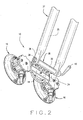
Figure 2 is a perspective view of the carrier system ofFig. 1 securing a bicycle; -
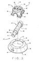
Figure 3 is an exploded view of a vacuum device; -
Figure 4 is a perspective view of a rear wheel mount; -
Figure 5 is a perspective view of an alternate embodiment of the wheel mount; -
Figure 6 is a plan view of a first alternate embodiment of the carrier system; -
Figure 7 is a plan view of a second alternate embodiment of the carrier system; -
Figure 8 is a perspective view of a third alternate embodiment of the carrier system; -
Figure 9 is a perspective view of a fourth alternate embodiment of the carrier system; -
Figure 10 is a plan view of a fifth alternate embodiment of the carrier system; -
Figure 11 is a plan view of a sixth alternate embodiment of the carrier system; -
Figure 12 is a perspective view of a seventh embodiment of the carrier system; -
Figure 13 is a perspective view of an eighth embodiment of the carrier system; -
Figure 14 is a perspective view of a carrier system which does not correspond to the claimed invention; -
Figure 15 is a perspective view of a carrier system which does not correspond to the claimed invention; -
Figure 16 is a perspective view of a carrier system which does not correspond to the claimed invention; -
Figure 17 is a perspective view of a further of the carrier system; -
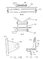
Figure 18 is a front view of locking clip; -
Figure 19 is a side view of the locking clip; -
Figure 20 is a perspective view of a bicycle secured to a vehicle with a locking system; -
Figure 21 is a perspective view of the locking clip engaged with a vehicle window; and -
Figure 22 is a plan view of a carrier system which does not correspond to the claimed invention. - Corresponding reference numerals indicate corresponding parts throughout the several figures of the drawings.
- As shown in
Figures 1-3 , an embodiment of the present disclosure, generally referred to as acarrier system 10, includes aframe member 12, amount 14 attached to theframe member 12 that is sized and shaped to couple with recreational articles, andvacuum devices 16 attached to theframe member 12 that can detachably attach to a mounting surface 17 of a vehicle. Thecarrier system 10 can couple with any recreational article, including, but not limited to, a bicycle, skis, a snowboard, a surfboard, a canoe, or a kayak. - The
frame 12 is generally alinear bar 18 with enlarged generallycircular portions 20 at each end that are each sized and shaped to mate withrespective vacuum devices 16. (Fig. 3 ). However, theportions 20 can be any shape and size capable of mating with thevacuum devices 16. In the embodiment ofFigs. 1-3 , theframe 12 mates with twovacuum devices 16, such as withfasteners 13, to provide enough vacuum strength to withstand the tensions, shear, and other forces on thecarrier system 10 during operation.Multiple vacuum devices 16 help stabilize the load and provide redundancy should one ormore vacuum device 16 fail. Asecurity member 22, such as a C-shaped handle, extends from theframe 12 so that an attachment member 1500, such as a tether, rope, cord, cable, or other member, along with alock 1502, can attach between thesecurity member 22 and the vehicle with asecurity clip 1504, which is described in more detail below. (Fig. 18-21 ). When secured to the vehicle, thesecurity member 22 acts as a theft deterrent. Preferably, theframe 12 is constructed from a material capable of handling the loads and tensions occurring during operation of the carrier system, such as metal, fiberglass, plastic, or other suitable materials. - The
mount 14 includes anattachment member 24 that attaches to theouter face 26 of theframe 12, such as by welding, adhesive, fasteners, or other appropriate means (Figs. 1-2 ). Extending from theattachment member 24 is askewer assembly 28 sized and shaped to couple with front orrear fork arms 35 of abicycle 37. Theskewer assembly 28 includes a generallytubular housing 30 that defines abore 32 along a center axis A-A. (Fig. 1 ). Generallycylindrical protrusions 34 extend outwardly from each end of thehousing 30 along the axis A-A. Theprotrusions 34 are shaped and sized to mate with thefront clevises 36 of the fork arms, which first requires removal of the wheel. To secure thefork arms 35 to theskewer assembly 28, askewer rod 36 inserts through thebore 32 and secures with a fasteners, such as anut 38 and acam clamp 40. Thecam clamp 40 can be tightened or loosened to secure and release the fork. Those skilled in the art will recognize that themount 14 can include any other suitable arrangement that properly secures a recreational article, such as, straps, fasteners, clamps, cables, brackets, tethers, and the like. In addition, themount 14 can include adaptors that accommodate various fork sizes and models, such as "Fork Up" available from Hurricane Components for 15mm or 20mm through-axle models. Also, the rear wheel of thebicycle 37 can be cradled in the rack instead of the front fork so that the front wheel does not need to be removed. - The
vacuum devices 16 are similar to the device disclosed inU.S. patent publication No. 2007/0216154 . Eachvacuum device 16 includes avacuum pad 42 and an attached vacuum pump 44 (Fig. 3 ). Ahousing 46 attaches to thevacuum pad 42 to enclose and secure thevacuum pump 44 to thevacuum pad 42. The housing is 46 shaped and sized to enclose thevacuum pump 44 while allowing for the attachment of an accessory and likewise to a surface of a vehicle. - The
vacuum pad 42 is generally a conical frustum that defines atop face 48 having threadedholes 50 to mount with thehousing 46 using fasteners 52. Thevacuum pad 42 also includes a recessedvacuum face 54 being generally parallel to thetop face 48, asloped side surface 56 extending between thetop face 48 and thevacuum face 54, and a generallycircumferential seating edge 58 along the perimeter of thevacuum face 54. In this arrangement, theseating edge 58 can seat with the mounting surface 17 of a vehicle to form a vacuum cavity 60. Thevacuum pad 42 defines achannel 62 extending from thetop face 48 to thevacuum face 54 and sized to mate with thevacuum pump 44.Release tabs 64 extend outwardly from theside surface 56. Therelease tabs 64 are generally t-shaped ribs that are shaped and sized to enhance rigidity of thepad 42 and help prevent release of thevacuum device 16 from the mounting surface 17, such as during exposure to warmer temperatures. - Preferably, the
pad 42 is made from a flexible material, such as, rubber, or plastic. However, thepad 42 can comprise any material that allows thevacuum pad 42 to seat with the mounting surface 17. Preferably, the material should not be prone to scuffing the mounting surface during installation or operation. In addition, the material can comprise any suitable color and may include other desirable attributes. For example, thepad 42 can be a reflective or glow-in-the-dark material so that It can be seen in dark environments. - The
pump 44 includes a generallycylindrical plunger 66 and ahollow cylinder 68 that defines a chamber 70 sized and shaped to receive theplunger 66. Theplunger 66 moves within the chamber 70 between a pressed position and a released position to create the vacuum cavity 60 between thevacuum face 54 and the mounting surface 17. Thecylinder 68 has an opening to the chamber 70 at one end and is closed at the opposite end. Atube 72 extends generally perpendicularly from the closed end of thecylinder 68. Thetube 72 is sized and shaped to insert into thechannel 62 of thevacuum pad 42 to provide fluid communication between the cylinder chamber 70 and the vacuum cavity 60. Theplunger 66 is sized to insert into thecylinder 68 with a sliding fit that allows theplunger 66 to move back and forth within thecylinder 68. Acheck valve 74 is positioned within the cylinder chamber 70 in communication with the chamber 70 and thetube 72 so that fluids and gases can only transfer into thetube 72 from outside of thecylinder 68. This allows thevacuum device 16 to be re-pumped without loss of remaining vacuum. In an alternate embodiment, an automatic pump can be used to increase the vacuum level of the vacuum device if it falls below a pre-determined level. In another alternate embodiment, a vacuum device includes a signaling component capable of indicating or sending a signal that indicates a loss of a designated amount of pressure, including, but not limited to, an audio signal, a visual signal, an electronic signal, or a wireless or Bluetooth® signal. For instance, a the signaling component can send a wireless signal to a wireless phone and, in conjunction with appropriate software on the phone, indicate the vacuum pressure. - The
plunger 66 is generally a rod with apush button 76 at one end, a seal 78 at the opposite end, and a biasing member 80 therebetween. The seal 78 is sized and shaped to seat against the inner wall of thecylinder 68. When theplunger 66 inserts into the cylinder chamber 70, the biasing member 80 biases theplunger 66 to the released position. The position of theplunger 66 in the released position will vary respective to the amount of vacuum pressure within the vacuum cavity 60. - An
indicator 82 positioned about the lower portion of thepush button 76 indicates to the operator the relative amount of vacuum pressure within the vacuum cavity 60. Theindicator 82 is a colored ring or sleeve sized and shaped to attach around the lower portion of thepush button 76. Theindicator 82 can be red, yellow or any color that is easily seen. Additionally, theindicator 82 can be a reflective or glow-in-the-dark material so that it can be seen in dark atmospheres and under water. When no vacuum pressure exists in the vacuum cavity 60, the biasing member 80 extends theplunger 66 to its most extended release position. In this position, theindicator 82 is fully visible. As the pressure increases in the vacuum cavity 60, the force of the vacuum lessens the bias of the biasing member 80, and, in turn, theplunger 66 extends less from the chamber 70 and less of theindicator 82 is visible. - The
housing 46 is a generally cylindrical member with a generally rectangular base which includes atop surface 84,bottom surface 86,first side 88, second side 90,third side 92, and pump side 94 (Fig. 3 ). Thebottom surface 86 of thehousing 46 defineshousing apertures 96 for attachment to thevacuum pad 42 with fasteners. Thetop surface 84 defines attachment apertures 98 for attachment of accessories with appropriate means, such as fasteners, straps, and other suitable members. Although,housing apertures 96 and attachment apertures 98 are shown ontop side 84 ofhousing 46, those skilled in the art will recognize thathousing apertures 96 and attachment apertures 98 can be located on anyside housing 46. Also, thehousing apertures 96 and attachment apertures 98 can be holes, slots, or any other configuration sized and shaped to accommodate different dimensions of various manufacturers' accessories. Thehousing 46 can be made from a variety of materials, including marine grade stainless steel, powder-coated aluminum, rubber or plastic. - In operation, an operator places the
vacuum face 54 ofpad 42 against a mounting surface 17 of a vehicle, which creates a vacuum cavity 60 between thevacuum face 54 of thepad 42 and mounting surface 17. This embodiment is preferably used with a pick up truck, with the mounting surface comprising the rear window of the truck. The operator repeatedly pushes theplunger 44 from the released position to the pressed position to remove fluid (air, gas, and/or water) from the vacuum cavity 60, thereby, reducing the pressure below the pressure the surrounding atmospheric pressure. This creates a vacuum such thatedge 58 and vacuum face 54 ofpad 42 seat against the mounting surface 17. A vacuum exists whenever the pressure within the space is less than the pressure that surrounds it. To obtain an adequate vacuum for operation, the operator should repeatedly press theplunger 66 until theindicator 82 is no longer visible when theplunger 66 is in the released position. If at any time during operation, theindicator 82 becomes visible indicating a loss of vacuum, the operator can again repeatedly push theplunger 66 until theindicator 82 is no longer visible. - Once the
carrier system 10 is attached to a mounting surface of a vehicle, a recreational device, such as a bicycle can be attached to themount 14. InFigs. 1-3 , the clevises of thefork arms 35 mate with theprotrusions 34 and are secured by inserting and tightening askewer rod 36. In this position, the rear bicycle wheel rests on the truck bed. When desired, theskewer rod 36 is loosened and thebicycle 37 can be removed. - To release the vacuum and remove the
carrier system 10, the operator lifts therelease tabs 64 on theside face 56 ofpad 42 away from the mounting surface 17. In other embodiments, a valve stem can be activated to release thevacuum device 16. Additionally, a twist button with a course thread located on the top face of thepad 42 can be used to release thevacuum device 16. - As shown in
Fig. 4 , thecarrier system 10 can also include arear wheel mount 91 for securing the rear wheel of abicycle 37 while the front of thebicycle 37 is secured to themount 14. Therear wheel mount 91 is avacuum device 16 that includes a securingstrap 93, such as a hook and loop material strap, for securing the rear wheel of thebicycle 37. Use of therear wheel mount 91 enhances the securement of thebicycle 37 to mount 14 and prevents the rear wheel of thebicycle 37 from contacting the vehicle. -
Fig. 5 illustrates an alternate embodiment of therear wheel mount 91, which includes a pair ofvacuum devices 16 mounted to asupport member 95. A pair of securingstraps 93, such as a hook and loop material strap, extend from thesupport member 95 for securing the rear wheel of thebicycle 37. Use of therear wheel mount 91 enhances the securement of up to twobicycles 37 tomounts 14 and prevents the rear wheel of the bicycles from contacting the vehicle. - The
carrier system 10 can also be embodied in the various forms ofFigs 6-20 . For ease of understanding, components common between the alternate embodiments are identified with similar reference numbers, except the reference numbers in the second embodiment include a "100" prefix. For example, the frame of the first embodiment is identified as 12, while a second embodiment with a similar frame is identified as 112. Naturally, any new components are identified with unique reference numbers. - In the first alternate embodiment of
Fig. 6 , thecarrier system 110 is similar to the embodiment ofFigs. 1-3 . However, the frame 112 has a longerlinear bar 118 to accommodate the attachment of amount 114 to eachcircular portion 120 withfasteners 113. Eachcircular portion 120 definesarcuate slots 115 shaped and sized to receive thefasteners 113 and provide for attachment of themounts 114 at a range of angular positions. Themounts 114 should be spaced at an appropriate distance from each other to accommodate the securement of recreational articles to respective mounts. In this way, thecarrier 110 can secure two recreational articles within the bed of a pick-up truck. - In the second alternate embodiment of
Figs. 7 , thecarrier system 210 is similar to the embodiment ofFigs. 1-3 . However, the frame 212 is generally V-shaped having twolinear bars 218 extending between three generally enlargedcircular portions 220. Avacuum device 216 is attached at eachcircular portion 220 and amount 214 is located on the opposite face of eachcircular portion 220. In this way, thecarrier 210 can secure three recreational articles within the bed of a pick-up truck. - In the third alternate embodiment of
Figs. 8 , thecarrier system 310 includes a frame 312 that is generally V-shaped having twolinear bars 318 extending between three generally rectangular portions 320. Thelinear bars 318 defineslits 317 to enhance the flexibility of the frame 312, which allows the frame 312 to bend to accommodate the curvature of the vehicle. Amount 314 is attached, such as withfasteners 313, to an outer surface of each rectangular portion 320. Avacuum device 316 is attached to the inner surface of the two outer rectangular portions 320. Twomore vacuum devices 316 are attached, such as withfasteners 313, to the inner surface of respectivelinear bars 318. In this way, thecarrier 310 can secure up to three recreational articles preferably to a rear window or trunk of a vehicle. - In the fourth alternate embodiment of
Figs. 9 , thecarrier system 410 includes a frame 412 having three generallyrectangular portions 420 arranged in a generally linear pattern. Therectangular portions 420 are connected by a segments 421 that define slits 417 to enhance the flexibility of the frame 412, which allows the frame 412 to bend to accommodate the curvature of the vehicle. Amount 414 is attached, such as withfasteners 413, to an outer surface of the centerrectangular portion 420. Avacuum device 416 is attached to the inner surface of the eachrectangular portion 420. In this way, thecarrier 410 can secure a recreational article preferably to a rear window or trunk of a vehicle. - In the fifth alternate embodiment of
Figs. 10 , thecarrier system 510 is similar to the embodiment ofFigs. 1-3 . However, theframe 512 has a secondlinear bar 523 extending generally downward and preferably at an angle of about 10° relative to the firstlinear bar 518, and terminating in a generallycircular portion 520.Slits 517 are defined at about equally spaced locations along theframe 512 to enhance the flexibility of theframe 512, which allows the frame to bend to accommodate the curvature of the vehicle roof. In this way, thecarrier 410 can secure a recreational article preferably to a rear window or trunk of a vehicle, preferably, with the twoupper vacuum devices 116 secured on the roof and thelower vacuum device 116 secured to the front windshield in view of the driver for monitoring of the vacuum pressure. - In the sixth alternate embodiment of
Fig. 11 , thecarrier system 610 is similar to the embodiment ofFigs. 1-3 . However, theframe 612 is a generally wing-shaped plate. A plurality ofvacuum devices 616, six are shown inFig. 11 , are attached, such as withfasteners 613, along the length of theframe 612 so that thecarrier system 610 can attach to the roof of a vehicle. Theframe 612 definesarcuate slots 615 shaped and sized to receive thefasteners 613 and provide for attachment of themounts 614 at a range of angular positions. Three mounts 614 are attached to the plate in a generally triangular arrangement to accommodate three bicycles. Three rear wheel mounts 91 are individually attached to the roof of a vehicle at a location to allow each rear wheel mount 91 to secure respective rear tires of each bicycle 637. In this way, thecarrier 610 can secure three recreational articles preferably on the roof of a vehicle.Slits 617 are defined at about equally spaced locations along theframe 612 to enhance the flexibility of theframe 612, which allows the frame to bend to accommodate the curvature of the vehicle roof. Theframe 612 can include a hinge to allow the frame to fold in half. If desired, theframe 612 is large enough to accommodate additional devices, such as, additional mounts, a front wheel holder, or attachments for other devices. - In the seventh alternate embodiment of
Figs. 12 , the frame 712 includes a generally triangular shaped portion 741 with a rearwardly extending ladder shaped portion 743. The ladder shaped portion 743 is angularly adjustable relative to the triangular shaped portion 741 to accommodate for different arrangements of vehicles and windshields. The ladder-shaped portion has two side members 745 connected by a plurality of crossbars 751. Cradle members 753 are attached along the lower portion 755 of each side member 745. Each cradle member 753 defines recesses 757 that are sized and shaped to receive the frame of a recreational article, such as a bicycle. Each recess 757 is positioned slightly forwardly and above of corresponding crossbar 751. This arrangement allows the operator to secure the frame of the bicycle to a respective crossbar 751 using a strap, tether or other securing member. In other words, the crossbars 751 are positioned to the rear and below of the each recess 757 so that the strap or other securing member pulls the bicycle into the deepest section of the recess 757. In this way, the carrier 710 can secure up to three recreational articles preferably to a rear window or trunk of a vehicle. - In the eighth alternate embodiment of
Figs. 13 , theframe 812 is generally ladder-shaped having twoside members 845 connected by a plurality ofcrossbars 851. Vacuum devices 816 are attached at the upper portion of theframe 812 at each intersection of theside members 845 and crossbars 854 for attachment to the rear of a vehicle. Cradle members 853 are attached along the lower portion of eachside member 845. Each cradle member 853 defines recesses 857 that are sized and shaped to receive the frame of a recreational article, such as a bicycle. Each recess 857 is positioned slightly forwardly and above of correspondingcrossbar 851. This arrangement allows the operator to secure the frame of the bicycle to arespective crossbar 851 using a strap, tether or other securing member. In other words, thecrossbars 851 are positioned to the rear and below of the each recess 857 so that the strap or other securing member pulls the bicycle into the deepest section of the recess 857. In this way, thecarrier 810 can secure up to three recreational articles preferably to a trunk of a vehicle. If desired, thecarrier 810 can include a telescoping support bar that extends from one of the crossbars 854 to the bumper of the vehicle. - In the carrier of
Figs. 14 , aball mount 961 extends generally perpendicularly from the top of thevacuum device 916. Asocket member 963 adjustably attaches to theball mount 961 with afastener 913 that allows rotational adjustment between theball mount 961 and thesocket member 963. Asecond vacuum device 916 attaches to thesocket mount 963 for attachment to an electronic device, such as an Ipad. In operation, the carrier 910 can secure a electronic device preferably to a dashboard of a vehicle. - In the carrier of
Figs. 15 , the carrier 1010 includes abracket 1068 for attachment to amount 14 for the vacuum device 1016, and aroller 1070 pivotally mounted to thebracket 1068. The roller 1072 is shaped and sized to seat against a kayak, canoe, or other vessel, such as an hourglass shape. In this way, the carrier 1010 can secure a recreational article preferably to a roof a vehicle. - In the carrier of
Figs. 16 , the carrier 1110 includes abracket 1112 for attachment to amount 1114 for the vacuum device 1116, and a support 1170 mounted to thebracket 1112. Thesupport 1172 is generally V-shaped for seating against a kayak, canoe, or other vessel, such as an hourglass shape. In this way, the carrier 1010 can secure a recreational article preferably to a roof a vehicle. - In the further embodiment of
Fig. 17 , the carrier system 1200 is similar to the embodiment ofFigs. 1-3 . However, themount 1214 is an L-shaped tube with aclamp 1215 positioned at the top end for engaging a recreational article. Themount 1214 is vertically adjustable. In this way, the carrier 1210 can secure a recreational article preferably to a rear window or trunk of a vehicle. In addition, the carrier system 1200 could also be used independently from a vehicle as a stand-alone workstand for a recreational article. - In the carrier of
Fig. 22 , the carrier 1310 includes asupport 1312 for attachment to amount 1314 for the vacuum device 1316, and a support 1370 mounted to thebracket 1312. Thesupport 1372 is shaped and sized to seat against a surfboard or other article. In this way, the carrier 1010 can secure a recreational article preferably to a roof a vehicle. - As mentioned above, the
carrier system 10 can include components for deterring theft of the carrier itself and any secured bicycles (Figs. 18-21 ). Asecurity clip 1504 is shaped and sized for engagement with avehicle window 1506 or avehicle door seam 1508. As shown inFigs. 18-19 , is a bracket having a generallyU-shaped segment 1510 defining arecess 1512 sized and shaped to receive avehicle window 1506 or avehicle seam 1508, aninternal tongue 1514 extending generally perpendicularly from the U-shaped segment, and an opposedexternal tongue 1516 extending generally perpendicularly from theU-shaped segment 1510. Abumper 1518 attaches to an extended portion of theU-shaped segment 1510. When installed, therecess 1512 receives thevehicle window 1506 so that the bumper seats against the outer surface of thewindow 1506 and theexternal tongue 1516 extends outwardly from thewindow 1506. An attachment member 1500, such as a tether, rope, cord, cable, or other member, along with alock 1502, can attach between ahole 1518 defined by theexternal tongue 1516 and the recreational article. If desired, any number ofsecurity clips 1504, attachment members 1500, andlocks 1502 can be used for added security. - In all of the embodiments, the frames are preferably made from a lightweight metal, such as aluminum. However, any suitable material can be used, including, but not limited to, steel, plastic, or composite material. Alternatively, the frame can be composed of a flexible material, such as Starboard® polymer material or other plastic, which eliminates the need for slits.
Claims (11)
- A carrier system (10) for a vehicle, comprising:a frame (12);a mount (14) attached to the frame, the mount being shaped and sized to detachably mate and secure a recreational article; andwherein a plurality of vacuum devices (16) is attached to the frame,each of the vacuum devices having a pad (42) shaped and sized to detachably seat with a vehicle to form a vacuum cavity (60), a plunger (66) attached to the pad and in fluid communication with the vacuum cavity, and an indicator (82) positioned on the plunger to indicate the level of vacuum pressure within the vacuum cavity,and wherein the carrier system further comprises a security clip shaped and sized for engagement with a vehicle seam;an attachment member shaped and sized for engagement between the recreational article and the security clip; anda lock configured for securement of the attachment member to the security clip.
- The carrier system of claim 1, further comprising:a bracket shaped and sized for detachable engagement with the mount;a support member attached to the bracket, the support member shaped and sized to seat a water recreational article.
- The carrier system of claim 1, wherein the mount comprises a skewer assembly configured for detachable mating with bicycle forks.
- The carrier system of claim 1, wherein the frame comprises
a socket member and
a ball mount moveably attached to each end of the socket member; and wherein
a vacuum device is attached to each ball mount, the each vacuum device having a pad shaped and sized to detachably seat with a vehicle to form a vacuum cavity, a plunger attached to the pad and in fluid communication with the vacuum cavity, and an indicator positioned on the plunger to indicate the level of vacuum pressure within the vacuum cavity. - The carrier system of claim 1, wherein the frame comprises a generally linear first bar with each end configured for attachment of the vacuum device.
- The carrier system of claim 1, wherein the frame comprises a generally v-shaped bar with each end and a vertex configured for attachment of the vacuum device and the mount.
- The carrier system of claim 1, wherein the frame comprises a generally triangular shaped plate configured for attachment of a plurality of vacuum devices and attachment of a plurality of mounts.
- The carrier system of claim 1, wherein the frame comprises a generally ladder shaped member extending from the frame and defining cradle portions configured to receive the recreational article.
- The carrier system of claim 1, wherein the mount comprises a roller configured for support of the recreational article.
- The carrier system of claim 1, wherein the mount comprises a v-shaped member configured for support of the recreational article.
- The carrier system of claim 1, wherein the mount comprises a clamp configured for securement of the recreational article.
Applications Claiming Priority (2)
| Application Number | Priority Date | Filing Date | Title |
|---|---|---|---|
| US24476909P | 2009-09-22 | 2009-09-22 | |
| PCT/US2010/049864 WO2011038029A2 (en) | 2009-09-22 | 2010-09-22 | Vacuum mounted carrier for a vehicle |
Publications (3)
| Publication Number | Publication Date |
|---|---|
| EP2480430A2 EP2480430A2 (en) | 2012-08-01 |
| EP2480430A4 EP2480430A4 (en) | 2013-05-08 |
| EP2480430B1 true EP2480430B1 (en) | 2014-05-07 |
Family
ID=43796470
Family Applications (1)
| Application Number | Title | Priority Date | Filing Date |
|---|---|---|---|
| EP10819409.3A Active EP2480430B1 (en) | 2009-09-22 | 2010-09-22 | Vacuum mounted carrier for a vehicle |
Country Status (8)
| Country | Link |
|---|---|
| US (1) | US20120168481A1 (en) |
| EP (1) | EP2480430B1 (en) |
| KR (1) | KR101860954B1 (en) |
| CA (1) | CA2775120C (en) |
| ES (1) | ES2485822T3 (en) |
| MX (1) | MX2012003463A (en) |
| PT (1) | PT2480430E (en) |
| WO (1) | WO2011038029A2 (en) |
Cited By (1)
| Publication number | Priority date | Publication date | Assignee | Title |
|---|---|---|---|---|
| EP4663488A1 (en) | 2024-06-13 | 2025-12-17 | Tigs Design & Engineering GmbH | Removable window wiper unit |
Families Citing this family (12)
| Publication number | Priority date | Publication date | Assignee | Title |
|---|---|---|---|---|
| US9821721B2 (en) | 2006-03-03 | 2017-11-21 | Charles L. Casagrande | Vacuum mounted carrier for a vehicle |
| WO2012142593A2 (en) * | 2011-04-14 | 2012-10-18 | Casagrande Charles L | Vacuum mount system for portable electronic device |
| WO2014043261A1 (en) * | 2012-09-11 | 2014-03-20 | Casagrande Charles L | Vacuum mounted carrier for a vehicle |
| US8939482B2 (en) | 2012-09-19 | 2015-01-27 | Kara M. Rasmussen | Support system for digital tablet devices |
| US9145158B2 (en) * | 2012-11-02 | 2015-09-29 | Luis Cruz | Tablet computer holder |
| DK178077B1 (en) * | 2013-11-18 | 2015-05-04 | Easystrap Holding Aps | Anordning til montering på overfladen af et køretøjs karrosseri |
| EP3350021B8 (en) * | 2015-09-15 | 2020-08-12 | Seasucker, LLC | Vacuum mounted carrier for a vehicle |
| EP3634811A4 (en) * | 2017-06-09 | 2020-12-02 | Seasucker, LLC | Reduced footprint vacuum mounted carriers for vehicles |
| KR102053018B1 (en) * | 2017-09-19 | 2019-12-06 | 문수만 | Electric vacuum suction type holding device |
| US20200269768A1 (en) * | 2019-02-26 | 2020-08-27 | Andrew Jarrard | Bicycle and Accessory Carrier Mount |
| CA3160100A1 (en) * | 2019-11-04 | 2021-05-14 | Seasucker, Llc | Vacuum mounted carrier for a vehicle |
| US11648883B1 (en) * | 2020-12-21 | 2023-05-16 | Neil Thomas Buttermore | Apparatus and method for active cargo carrier mounting system |
Family Cites Families (26)
| Publication number | Priority date | Publication date | Assignee | Title |
|---|---|---|---|---|
| US2157001A (en) * | 1938-10-06 | 1939-05-02 | Charles E Morley | Clothes hanger for automobiles |
| US2474513A (en) * | 1948-01-17 | 1949-06-28 | Paul H Behrens | Bracket attachment for motor vehicle windows |
| US3712524A (en) * | 1971-03-19 | 1973-01-23 | R Ames | Boat loader for automobiles |
| US3924787A (en) * | 1974-01-07 | 1975-12-09 | James Pershing Gothrup | Carrier bracket for attaching a bicycle relative to a motor vehicle's bumper |
| US4039106A (en) * | 1975-04-18 | 1977-08-02 | Joseph V. Graber | Automobile bicycle carrier |
| US4231501A (en) * | 1978-01-13 | 1980-11-04 | Goode David P | Window mount ski rack |
| US4366605A (en) * | 1981-02-02 | 1983-01-04 | Mckenney John | Anti-theft cable device for car top carriers |
| AU521966B3 (en) * | 1982-02-12 | 1982-06-17 | Warwick Peter Freeland | Securing an object to a vehicle |
| US4941602A (en) * | 1987-12-29 | 1990-07-17 | Wells Todd A | Air drying air chilling container attachable to a car window |
| US4842148A (en) * | 1988-02-23 | 1989-06-27 | Bowman Tracy L | Quick release bicycle rack |
| US5184858A (en) * | 1991-09-17 | 1993-02-09 | Toyo Sangyo Co., Ltd. | Sucker for plate glass |
| US5372287A (en) * | 1992-10-05 | 1994-12-13 | Deguevara; Orlando | Article carrier |
| US5390837A (en) * | 1993-02-11 | 1995-02-21 | Ruffolo Enterprises, Inc. | Snowboard rack |
| US5474065A (en) * | 1994-04-04 | 1995-12-12 | Graphic Controls Corporation | Non-invasive fetal probe |
| US5639134A (en) * | 1996-01-16 | 1997-06-17 | Auto Glass Specialists, Inc. | Multiposition windshield lifting attachment |
| US5904463A (en) * | 1998-07-30 | 1999-05-18 | Christensen; Robyn M. | Cargo loading and carrying device for use on a motor vechicle roof |
| TW447424U (en) * | 2000-05-16 | 2001-07-21 | Formosa Saint Jose Corp | Retaining device for sled capable of adjusting position |
| US20020053581A1 (en) * | 2000-11-08 | 2002-05-09 | Peschmann Joseph J. | Vehicle roof mounted bicycle carrier |
| HK1053581A2 (en) * | 2002-08-01 | 2003-10-10 | 金峰塑胶制品有限公司 | Suction-adhesive device |
| US6827396B1 (en) * | 2004-03-29 | 2004-12-07 | Charles C. Jewell | Remora powerboat chair |
| US7448812B2 (en) * | 2004-05-27 | 2008-11-11 | Heibel Thomas S | Camera mount |
| WO2006019996A2 (en) * | 2004-07-14 | 2006-02-23 | Palmetto West Trading Company, Llc | Ball mounted mounting device |
| CN2779138Y (en) * | 2005-02-04 | 2006-05-10 | 南京德朔实业有限公司 | Fixing device with a suction cup |
| US20070216154A1 (en) * | 2006-03-03 | 2007-09-20 | Casagrande Charles L | Mounting system and methods for attaching accessory components |
| US7707765B2 (en) * | 2007-03-23 | 2010-05-04 | Lih Yann Industrial Co., Ltd. | Fishing rod fixing device |
| US8505861B2 (en) * | 2007-10-26 | 2013-08-13 | Jeffrey D. Carnevali | Suction cup mounting platform having flexible base |
-
2010
- 2010-09-22 WO PCT/US2010/049864 patent/WO2011038029A2/en not_active Ceased
- 2010-09-22 ES ES10819409.3T patent/ES2485822T3/en active Active
- 2010-09-22 CA CA2775120A patent/CA2775120C/en active Active
- 2010-09-22 EP EP10819409.3A patent/EP2480430B1/en active Active
- 2010-09-22 US US13/497,653 patent/US20120168481A1/en not_active Abandoned
- 2010-09-22 MX MX2012003463A patent/MX2012003463A/en active IP Right Grant
- 2010-09-22 PT PT108194093T patent/PT2480430E/en unknown
- 2010-09-22 KR KR1020127010294A patent/KR101860954B1/en not_active Expired - Fee Related
Cited By (2)
| Publication number | Priority date | Publication date | Assignee | Title |
|---|---|---|---|---|
| EP4663488A1 (en) | 2024-06-13 | 2025-12-17 | Tigs Design & Engineering GmbH | Removable window wiper unit |
| WO2025256778A1 (en) | 2024-06-13 | 2025-12-18 | Tigs Design & Engineering Gmbh | Removable window wiper unit |
Also Published As
| Publication number | Publication date |
|---|---|
| WO2011038029A3 (en) | 2011-10-20 |
| KR20120094917A (en) | 2012-08-27 |
| EP2480430A2 (en) | 2012-08-01 |
| US20120168481A1 (en) | 2012-07-05 |
| PT2480430E (en) | 2014-07-30 |
| AU2010298318A1 (en) | 2012-05-03 |
| ES2485822T3 (en) | 2014-08-14 |
| MX2012003463A (en) | 2012-07-23 |
| WO2011038029A2 (en) | 2011-03-31 |
| EP2480430A4 (en) | 2013-05-08 |
| CA2775120A1 (en) | 2011-03-31 |
| KR101860954B1 (en) | 2018-05-24 |
| CA2775120C (en) | 2020-09-22 |
Similar Documents
| Publication | Publication Date | Title |
|---|---|---|
| US11752948B2 (en) | Vacuum mounted carrier for a vehicle | |
| EP2480430B1 (en) | Vacuum mounted carrier for a vehicle | |
| EP3350021B1 (en) | Vacuum mounted carrier for a vehicle | |
| US11541824B2 (en) | Reduced footprint vacuum mounted hitch rack carrier systems for vehicles | |
| US9174585B2 (en) | Devices and methods for securing skis, snowboards, etc. to crossbars of vehicle roof racks | |
| US10894514B2 (en) | Wheel mounted cargo carrier | |
| WO2007001910A2 (en) | Universal attachment system | |
| WO2014043261A1 (en) | Vacuum mounted carrier for a vehicle | |
| US6863199B2 (en) | Snowboard rack for snowmobiles | |
| AU2010298318B2 (en) | Vacuum mounted carrier for a vehicle | |
| US5509592A (en) | Outboard motor carrier for vehicles | |
| US20030066853A1 (en) | Mounting apparatus for all terrain vehicles |
Legal Events
| Date | Code | Title | Description |
|---|---|---|---|
| PUAI | Public reference made under article 153(3) epc to a published international application that has entered the european phase |
Free format text: ORIGINAL CODE: 0009012 |
|
| 17P | Request for examination filed |
Effective date: 20120412 |
|
| AK | Designated contracting states |
Kind code of ref document: A2 Designated state(s): AL AT BE BG CH CY CZ DE DK EE ES FI FR GB GR HR HU IE IS IT LI LT LU LV MC MK MT NL NO PL PT RO SE SI SK SM TR |
|
| DAX | Request for extension of the european patent (deleted) | ||
| A4 | Supplementary search report drawn up and despatched |
Effective date: 20130410 |
|
| RIC1 | Information provided on ipc code assigned before grant |
Ipc: B60R 9/08 20060101AFI20130404BHEP Ipc: B60R 9/00 20060101ALI20130404BHEP Ipc: B60R 11/00 20060101ALI20130404BHEP |
|
| GRAP | Despatch of communication of intention to grant a patent |
Free format text: ORIGINAL CODE: EPIDOSNIGR1 |
|
| INTG | Intention to grant announced |
Effective date: 20131217 |
|
| GRAS | Grant fee paid |
Free format text: ORIGINAL CODE: EPIDOSNIGR3 |
|
| GRAA | (expected) grant |
Free format text: ORIGINAL CODE: 0009210 |
|
| AK | Designated contracting states |
Kind code of ref document: B1 Designated state(s): AL AT BE BG CH CY CZ DE DK EE ES FI FR GB GR HR HU IE IS IT LI LT LU LV MC MK MT NL NO PL PT RO SE SI SK SM TR |
|
| REG | Reference to a national code |
Ref country code: GB Ref legal event code: FG4D |
|
| REG | Reference to a national code |
Ref country code: AT Ref legal event code: REF Ref document number: 666361 Country of ref document: AT Kind code of ref document: T Effective date: 20140515 |
|
| REG | Reference to a national code |
Ref country code: IE Ref legal event code: FG4D |
|
| REG | Reference to a national code |
Ref country code: DE Ref legal event code: R096 Ref document number: 602010015993 Country of ref document: DE Effective date: 20140618 |
|
| REG | Reference to a national code |
Ref country code: PT Ref legal event code: SC4A Free format text: AVAILABILITY OF NATIONAL TRANSLATION Effective date: 20140723 |
|
| REG | Reference to a national code |
Ref country code: CH Ref legal event code: NV Representative=s name: DR. ALEXANDER MILLER, LL.M. RECHTSANWALT (D), CH |
|
| REG | Reference to a national code |
Ref country code: ES Ref legal event code: FG2A Ref document number: 2485822 Country of ref document: ES Kind code of ref document: T3 Effective date: 20140814 |
|
| REG | Reference to a national code |
Ref country code: NL Ref legal event code: T3 |
|
| REG | Reference to a national code |
Ref country code: AT Ref legal event code: MK05 Ref document number: 666361 Country of ref document: AT Kind code of ref document: T Effective date: 20140507 |
|
| REG | Reference to a national code |
Ref country code: LT Ref legal event code: MG4D |
|
| PG25 | Lapsed in a contracting state [announced via postgrant information from national office to epo] |
Ref country code: GR Free format text: LAPSE BECAUSE OF FAILURE TO SUBMIT A TRANSLATION OF THE DESCRIPTION OR TO PAY THE FEE WITHIN THE PRESCRIBED TIME-LIMIT Effective date: 20140808 Ref country code: NO Free format text: LAPSE BECAUSE OF FAILURE TO SUBMIT A TRANSLATION OF THE DESCRIPTION OR TO PAY THE FEE WITHIN THE PRESCRIBED TIME-LIMIT Effective date: 20140807 Ref country code: LT Free format text: LAPSE BECAUSE OF FAILURE TO SUBMIT A TRANSLATION OF THE DESCRIPTION OR TO PAY THE FEE WITHIN THE PRESCRIBED TIME-LIMIT Effective date: 20140507 Ref country code: IS Free format text: LAPSE BECAUSE OF FAILURE TO SUBMIT A TRANSLATION OF THE DESCRIPTION OR TO PAY THE FEE WITHIN THE PRESCRIBED TIME-LIMIT Effective date: 20140907 Ref country code: FI Free format text: LAPSE BECAUSE OF FAILURE TO SUBMIT A TRANSLATION OF THE DESCRIPTION OR TO PAY THE FEE WITHIN THE PRESCRIBED TIME-LIMIT Effective date: 20140507 Ref country code: CY Free format text: LAPSE BECAUSE OF FAILURE TO SUBMIT A TRANSLATION OF THE DESCRIPTION OR TO PAY THE FEE WITHIN THE PRESCRIBED TIME-LIMIT Effective date: 20140507 |
|
| PG25 | Lapsed in a contracting state [announced via postgrant information from national office to epo] |
Ref country code: SE Free format text: LAPSE BECAUSE OF FAILURE TO SUBMIT A TRANSLATION OF THE DESCRIPTION OR TO PAY THE FEE WITHIN THE PRESCRIBED TIME-LIMIT Effective date: 20140507 Ref country code: PL Free format text: LAPSE BECAUSE OF FAILURE TO SUBMIT A TRANSLATION OF THE DESCRIPTION OR TO PAY THE FEE WITHIN THE PRESCRIBED TIME-LIMIT Effective date: 20140507 Ref country code: AT Free format text: LAPSE BECAUSE OF FAILURE TO SUBMIT A TRANSLATION OF THE DESCRIPTION OR TO PAY THE FEE WITHIN THE PRESCRIBED TIME-LIMIT Effective date: 20140507 Ref country code: LV Free format text: LAPSE BECAUSE OF FAILURE TO SUBMIT A TRANSLATION OF THE DESCRIPTION OR TO PAY THE FEE WITHIN THE PRESCRIBED TIME-LIMIT Effective date: 20140507 Ref country code: HR Free format text: LAPSE BECAUSE OF FAILURE TO SUBMIT A TRANSLATION OF THE DESCRIPTION OR TO PAY THE FEE WITHIN THE PRESCRIBED TIME-LIMIT Effective date: 20140507 |
|
| PG25 | Lapsed in a contracting state [announced via postgrant information from national office to epo] |
Ref country code: SK Free format text: LAPSE BECAUSE OF FAILURE TO SUBMIT A TRANSLATION OF THE DESCRIPTION OR TO PAY THE FEE WITHIN THE PRESCRIBED TIME-LIMIT Effective date: 20140507 Ref country code: RO Free format text: LAPSE BECAUSE OF FAILURE TO SUBMIT A TRANSLATION OF THE DESCRIPTION OR TO PAY THE FEE WITHIN THE PRESCRIBED TIME-LIMIT Effective date: 20140507 Ref country code: EE Free format text: LAPSE BECAUSE OF FAILURE TO SUBMIT A TRANSLATION OF THE DESCRIPTION OR TO PAY THE FEE WITHIN THE PRESCRIBED TIME-LIMIT Effective date: 20140507 Ref country code: CZ Free format text: LAPSE BECAUSE OF FAILURE TO SUBMIT A TRANSLATION OF THE DESCRIPTION OR TO PAY THE FEE WITHIN THE PRESCRIBED TIME-LIMIT Effective date: 20140507 Ref country code: DK Free format text: LAPSE BECAUSE OF FAILURE TO SUBMIT A TRANSLATION OF THE DESCRIPTION OR TO PAY THE FEE WITHIN THE PRESCRIBED TIME-LIMIT Effective date: 20140507 |
|
| REG | Reference to a national code |
Ref country code: DE Ref legal event code: R097 Ref document number: 602010015993 Country of ref document: DE |
|
| PLBE | No opposition filed within time limit |
Free format text: ORIGINAL CODE: 0009261 |
|
| STAA | Information on the status of an ep patent application or granted ep patent |
Free format text: STATUS: NO OPPOSITION FILED WITHIN TIME LIMIT |
|
| 26N | No opposition filed |
Effective date: 20150210 |
|
| PG25 | Lapsed in a contracting state [announced via postgrant information from national office to epo] |
Ref country code: LU Free format text: LAPSE BECAUSE OF FAILURE TO SUBMIT A TRANSLATION OF THE DESCRIPTION OR TO PAY THE FEE WITHIN THE PRESCRIBED TIME-LIMIT Effective date: 20140922 Ref country code: MC Free format text: LAPSE BECAUSE OF FAILURE TO SUBMIT A TRANSLATION OF THE DESCRIPTION OR TO PAY THE FEE WITHIN THE PRESCRIBED TIME-LIMIT Effective date: 20140507 |
|
| REG | Reference to a national code |
Ref country code: DE Ref legal event code: R097 Ref document number: 602010015993 Country of ref document: DE Effective date: 20150210 |
|
| REG | Reference to a national code |
Ref country code: FR Ref legal event code: ST Effective date: 20150529 |
|
| PG25 | Lapsed in a contracting state [announced via postgrant information from national office to epo] |
Ref country code: SI Free format text: LAPSE BECAUSE OF FAILURE TO SUBMIT A TRANSLATION OF THE DESCRIPTION OR TO PAY THE FEE WITHIN THE PRESCRIBED TIME-LIMIT Effective date: 20140507 |
|
| PG25 | Lapsed in a contracting state [announced via postgrant information from national office to epo] |
Ref country code: FR Free format text: LAPSE BECAUSE OF NON-PAYMENT OF DUE FEES Effective date: 20140930 |
|
| PG25 | Lapsed in a contracting state [announced via postgrant information from national office to epo] |
Ref country code: SM Free format text: LAPSE BECAUSE OF FAILURE TO SUBMIT A TRANSLATION OF THE DESCRIPTION OR TO PAY THE FEE WITHIN THE PRESCRIBED TIME-LIMIT Effective date: 20140507 |
|
| PG25 | Lapsed in a contracting state [announced via postgrant information from national office to epo] |
Ref country code: MT Free format text: LAPSE BECAUSE OF FAILURE TO SUBMIT A TRANSLATION OF THE DESCRIPTION OR TO PAY THE FEE WITHIN THE PRESCRIBED TIME-LIMIT Effective date: 20140507 Ref country code: BG Free format text: LAPSE BECAUSE OF FAILURE TO SUBMIT A TRANSLATION OF THE DESCRIPTION OR TO PAY THE FEE WITHIN THE PRESCRIBED TIME-LIMIT Effective date: 20140507 |
|
| PG25 | Lapsed in a contracting state [announced via postgrant information from national office to epo] |
Ref country code: HU Free format text: LAPSE BECAUSE OF FAILURE TO SUBMIT A TRANSLATION OF THE DESCRIPTION OR TO PAY THE FEE WITHIN THE PRESCRIBED TIME-LIMIT; INVALID AB INITIO Effective date: 20100922 Ref country code: TR Free format text: LAPSE BECAUSE OF FAILURE TO SUBMIT A TRANSLATION OF THE DESCRIPTION OR TO PAY THE FEE WITHIN THE PRESCRIBED TIME-LIMIT Effective date: 20140507 |
|
| PG25 | Lapsed in a contracting state [announced via postgrant information from national office to epo] |
Ref country code: MK Free format text: LAPSE BECAUSE OF FAILURE TO SUBMIT A TRANSLATION OF THE DESCRIPTION OR TO PAY THE FEE WITHIN THE PRESCRIBED TIME-LIMIT Effective date: 20140507 |
|
| PG25 | Lapsed in a contracting state [announced via postgrant information from national office to epo] |
Ref country code: AL Free format text: LAPSE BECAUSE OF FAILURE TO SUBMIT A TRANSLATION OF THE DESCRIPTION OR TO PAY THE FEE WITHIN THE PRESCRIBED TIME-LIMIT Effective date: 20140507 |
|
| PGFP | Annual fee paid to national office [announced via postgrant information from national office to epo] |
Ref country code: PT Payment date: 20190909 Year of fee payment: 10 |
|
| PG25 | Lapsed in a contracting state [announced via postgrant information from national office to epo] |
Ref country code: PT Free format text: LAPSE BECAUSE OF NON-PAYMENT OF DUE FEES Effective date: 20210413 |
|
| PGFP | Annual fee paid to national office [announced via postgrant information from national office to epo] |
Ref country code: DE Payment date: 20250331 Year of fee payment: 15 |
|
| PGFP | Annual fee paid to national office [announced via postgrant information from national office to epo] |
Ref country code: NL Payment date: 20250324 Year of fee payment: 15 |
|
| PGFP | Annual fee paid to national office [announced via postgrant information from national office to epo] |
Ref country code: IE Payment date: 20250326 Year of fee payment: 15 |
|
| PGFP | Annual fee paid to national office [announced via postgrant information from national office to epo] |
Ref country code: CH Payment date: 20250324 Year of fee payment: 15 Ref country code: BE Payment date: 20250326 Year of fee payment: 15 |
|
| PGFP | Annual fee paid to national office [announced via postgrant information from national office to epo] |
Ref country code: GB Payment date: 20250327 Year of fee payment: 15 Ref country code: IT Payment date: 20250324 Year of fee payment: 15 |
|
| PGFP | Annual fee paid to national office [announced via postgrant information from national office to epo] |
Ref country code: ES Payment date: 20250401 Year of fee payment: 15 |