EP2480268B1 - Assembly and indicator for a drug delivery device - Google Patents
Assembly and indicator for a drug delivery device Download PDFInfo
- Publication number
- EP2480268B1 EP2480268B1 EP10762886.9A EP10762886A EP2480268B1 EP 2480268 B1 EP2480268 B1 EP 2480268B1 EP 10762886 A EP10762886 A EP 10762886A EP 2480268 B1 EP2480268 B1 EP 2480268B1
- Authority
- EP
- European Patent Office
- Prior art keywords
- indicator
- indication
- piston rod
- indication position
- detent
- Prior art date
- Legal status (The legal status is an assumption and is not a legal conclusion. Google has not performed a legal analysis and makes no representation as to the accuracy of the status listed.)
- Active
Links
- 238000012377 drug delivery Methods 0.000 title claims description 52
- 229940079593 drug Drugs 0.000 claims description 40
- 239000003814 drug Substances 0.000 claims description 40
- 230000003993 interaction Effects 0.000 claims description 35
- 230000007704 transition Effects 0.000 claims description 2
- JUFFVKRROAPVBI-PVOYSMBESA-N chembl1210015 Chemical compound C([C@@H](C(=O)N[C@@H]([C@@H](C)CC)C(=O)N[C@@H](CCC(O)=O)C(=O)N[C@@H](CC=1C2=CC=CC=C2NC=1)C(=O)N[C@@H](CC(C)C)C(=O)N[C@@H](CCCCN)C(=O)N[C@@H](CC(=O)N[C@H]1[C@@H]([C@@H](O)[C@H](O[C@H]2[C@@H]([C@@H](O)[C@@H](O)[C@@H](CO[C@]3(O[C@@H](C[C@H](O)[C@H](O)CO)[C@H](NC(C)=O)[C@@H](O)C3)C(O)=O)O2)O)[C@@H](CO)O1)NC(C)=O)C(=O)NCC(=O)NCC(=O)N1[C@@H](CCC1)C(=O)N[C@@H](CO)C(=O)N[C@@H](CO)C(=O)NCC(=O)N[C@@H](C)C(=O)N1[C@@H](CCC1)C(=O)N1[C@@H](CCC1)C(=O)N1[C@@H](CCC1)C(=O)N[C@@H](CO)C(N)=O)NC(=O)[C@H](CC(C)C)NC(=O)[C@H](CCCNC(N)=N)NC(=O)[C@@H](NC(=O)[C@H](C)NC(=O)[C@H](CCC(O)=O)NC(=O)[C@H](CCC(O)=O)NC(=O)[C@H](CCC(O)=O)NC(=O)[C@H](CCSC)NC(=O)[C@H](CCC(N)=O)NC(=O)[C@H](CCCCN)NC(=O)[C@H](CO)NC(=O)[C@H](CC(C)C)NC(=O)[C@H](CC(O)=O)NC(=O)[C@H](CO)NC(=O)[C@@H](NC(=O)[C@H](CC=1C=CC=CC=1)NC(=O)[C@@H](NC(=O)CNC(=O)[C@H](CCC(O)=O)NC(=O)CNC(=O)[C@@H](N)CC=1NC=NC=1)[C@@H](C)O)[C@@H](C)O)C(C)C)C1=CC=CC=C1 JUFFVKRROAPVBI-PVOYSMBESA-N 0.000 description 50
- 108010011459 Exenatide Proteins 0.000 description 47
- 229960001519 exenatide Drugs 0.000 description 47
- 101000976075 Homo sapiens Insulin Proteins 0.000 description 22
- PBGKTOXHQIOBKM-FHFVDXKLSA-N insulin (human) Chemical compound C([C@@H](C(=O)N[C@@H](CC(C)C)C(=O)N[C@H]1CSSC[C@H]2C(=O)N[C@H](C(=O)N[C@@H](CO)C(=O)N[C@H](C(=O)N[C@H](C(N[C@@H](CO)C(=O)N[C@@H](CC(C)C)C(=O)N[C@@H](CC=3C=CC(O)=CC=3)C(=O)N[C@@H](CCC(N)=O)C(=O)N[C@@H](CC(C)C)C(=O)N[C@@H](CCC(O)=O)C(=O)N[C@@H](CC(N)=O)C(=O)N[C@@H](CC=3C=CC(O)=CC=3)C(=O)N[C@@H](CSSC[C@H](NC(=O)[C@H](C(C)C)NC(=O)[C@H](CC(C)C)NC(=O)[C@H](CC=3C=CC(O)=CC=3)NC(=O)[C@H](CC(C)C)NC(=O)[C@H](C)NC(=O)[C@H](CCC(O)=O)NC(=O)[C@H](C(C)C)NC(=O)[C@H](CC(C)C)NC(=O)[C@H](CC=3NC=NC=3)NC(=O)[C@H](CO)NC(=O)CNC1=O)C(=O)NCC(=O)N[C@@H](CCC(O)=O)C(=O)N[C@@H](CCCNC(N)=N)C(=O)NCC(=O)N[C@@H](CC=1C=CC=CC=1)C(=O)N[C@@H](CC=1C=CC=CC=1)C(=O)N[C@@H](CC=1C=CC(O)=CC=1)C(=O)N[C@@H]([C@@H](C)O)C(=O)N1[C@@H](CCC1)C(=O)N[C@@H](CCCCN)C(=O)N[C@@H]([C@@H](C)O)C(O)=O)C(=O)N[C@@H](CC(N)=O)C(O)=O)=O)CSSC[C@@H](C(N2)=O)NC(=O)[C@H](CCC(N)=O)NC(=O)[C@H](CCC(O)=O)NC(=O)[C@H](C(C)C)NC(=O)[C@@H](NC(=O)CN)[C@@H](C)CC)[C@@H](C)CC)[C@@H](C)O)NC(=O)[C@H](CCC(N)=O)NC(=O)[C@H](CC(N)=O)NC(=O)[C@@H](NC(=O)[C@@H](N)CC=1C=CC=CC=1)C(C)C)C1=CN=CN1 PBGKTOXHQIOBKM-FHFVDXKLSA-N 0.000 description 21
- 150000003839 salts Chemical class 0.000 description 8
- 150000001875 compounds Chemical class 0.000 description 7
- 230000037452 priming Effects 0.000 description 6
- 238000006073 displacement reaction Methods 0.000 description 5
- NOESYZHRGYRDHS-UHFFFAOYSA-N insulin Chemical compound N1C(=O)C(NC(=O)C(CCC(N)=O)NC(=O)C(CCC(O)=O)NC(=O)C(C(C)C)NC(=O)C(NC(=O)CN)C(C)CC)CSSCC(C(NC(CO)C(=O)NC(CC(C)C)C(=O)NC(CC=2C=CC(O)=CC=2)C(=O)NC(CCC(N)=O)C(=O)NC(CC(C)C)C(=O)NC(CCC(O)=O)C(=O)NC(CC(N)=O)C(=O)NC(CC=2C=CC(O)=CC=2)C(=O)NC(CSSCC(NC(=O)C(C(C)C)NC(=O)C(CC(C)C)NC(=O)C(CC=2C=CC(O)=CC=2)NC(=O)C(CC(C)C)NC(=O)C(C)NC(=O)C(CCC(O)=O)NC(=O)C(C(C)C)NC(=O)C(CC(C)C)NC(=O)C(CC=2NC=NC=2)NC(=O)C(CO)NC(=O)CNC2=O)C(=O)NCC(=O)NC(CCC(O)=O)C(=O)NC(CCCNC(N)=N)C(=O)NCC(=O)NC(CC=3C=CC=CC=3)C(=O)NC(CC=3C=CC=CC=3)C(=O)NC(CC=3C=CC(O)=CC=3)C(=O)NC(C(C)O)C(=O)N3C(CCC3)C(=O)NC(CCCCN)C(=O)NC(C)C(O)=O)C(=O)NC(CC(N)=O)C(O)=O)=O)NC(=O)C(C(C)CC)NC(=O)C(CO)NC(=O)C(C(C)O)NC(=O)C1CSSCC2NC(=O)C(CC(C)C)NC(=O)C(NC(=O)C(CCC(N)=O)NC(=O)C(CC(N)=O)NC(=O)C(NC(=O)C(N)CC=1C=CC=CC=1)C(C)C)CC1=CN=CN1 NOESYZHRGYRDHS-UHFFFAOYSA-N 0.000 description 5
- 108010088406 Glucagon-Like Peptides Proteins 0.000 description 4
- 206010012601 diabetes mellitus Diseases 0.000 description 4
- 108090000765 processed proteins & peptides Proteins 0.000 description 4
- 230000000717 retained effect Effects 0.000 description 4
- HTTJABKRGRZYRN-UHFFFAOYSA-N Heparin Chemical compound OC1C(NC(=O)C)C(O)OC(COS(O)(=O)=O)C1OC1C(OS(O)(=O)=O)C(O)C(OC2C(C(OS(O)(=O)=O)C(OC3C(C(O)C(O)C(O3)C(O)=O)OS(O)(=O)=O)C(CO)O2)NS(O)(=O)=O)C(C(O)=O)O1 HTTJABKRGRZYRN-UHFFFAOYSA-N 0.000 description 3
- 150000004676 glycans Chemical class 0.000 description 3
- 229960002897 heparin Drugs 0.000 description 3
- 229920000669 heparin Polymers 0.000 description 3
- 229940088597 hormone Drugs 0.000 description 3
- 239000005556 hormone Substances 0.000 description 3
- 238000007373 indentation Methods 0.000 description 3
- 239000003055 low molecular weight heparin Substances 0.000 description 3
- 229940127215 low-molecular weight heparin Drugs 0.000 description 3
- 238000004519 manufacturing process Methods 0.000 description 3
- 230000013011 mating Effects 0.000 description 3
- 229920001282 polysaccharide Polymers 0.000 description 3
- 239000005017 polysaccharide Substances 0.000 description 3
- 208000004476 Acute Coronary Syndrome Diseases 0.000 description 2
- 208000002249 Diabetes Complications Diseases 0.000 description 2
- 206010012689 Diabetic retinopathy Diseases 0.000 description 2
- 102000004877 Insulin Human genes 0.000 description 2
- 108090001061 Insulin Proteins 0.000 description 2
- 108010092217 Long-Acting Insulin Proteins 0.000 description 2
- 229940100066 Long-acting insulin Drugs 0.000 description 2
- 108010026951 Short-Acting Insulin Proteins 0.000 description 2
- 229940123958 Short-acting insulin Drugs 0.000 description 2
- 206010057362 Underdose Diseases 0.000 description 2
- 239000002253 acid Substances 0.000 description 2
- 150000001447 alkali salts Chemical class 0.000 description 2
- 239000000122 growth hormone Substances 0.000 description 2
- 238000002347 injection Methods 0.000 description 2
- 239000007924 injection Substances 0.000 description 2
- 229940125396 insulin Drugs 0.000 description 2
- 231100000518 lethal Toxicity 0.000 description 2
- 230000001665 lethal effect Effects 0.000 description 2
- 239000007788 liquid Substances 0.000 description 2
- 238000011321 prophylaxis Methods 0.000 description 2
- 239000012453 solvate Substances 0.000 description 2
- 238000011282 treatment Methods 0.000 description 2
- 230000000007 visual effect Effects 0.000 description 2
- 239000002699 waste material Substances 0.000 description 2
- KIUKXJAPPMFGSW-DNGZLQJQSA-N (2S,3S,4S,5R,6R)-6-[(2S,3R,4R,5S,6R)-3-Acetamido-2-[(2S,3S,4R,5R,6R)-6-[(2R,3R,4R,5S,6R)-3-acetamido-2,5-dihydroxy-6-(hydroxymethyl)oxan-4-yl]oxy-2-carboxy-4,5-dihydroxyoxan-3-yl]oxy-5-hydroxy-6-(hydroxymethyl)oxan-4-yl]oxy-3,4,5-trihydroxyoxane-2-carboxylic acid Chemical compound CC(=O)N[C@H]1[C@H](O)O[C@H](CO)[C@@H](O)[C@@H]1O[C@H]1[C@H](O)[C@@H](O)[C@H](O[C@H]2[C@@H]([C@@H](O[C@H]3[C@@H]([C@@H](O)[C@H](O)[C@H](O3)C(O)=O)O)[C@H](O)[C@@H](CO)O2)NC(C)=O)[C@@H](C(O)=O)O1 KIUKXJAPPMFGSW-DNGZLQJQSA-N 0.000 description 1
- 125000004169 (C1-C6) alkyl group Chemical group 0.000 description 1
- 125000001831 (C6-C10) heteroaryl group Chemical group 0.000 description 1
- 208000035285 Allergic Seasonal Rhinitis Diseases 0.000 description 1
- QGZKDVFQNNGYKY-UHFFFAOYSA-O Ammonium Chemical compound [NH4+] QGZKDVFQNNGYKY-UHFFFAOYSA-O 0.000 description 1
- 206010002383 Angina Pectoris Diseases 0.000 description 1
- 201000001320 Atherosclerosis Diseases 0.000 description 1
- 108010037003 Buserelin Proteins 0.000 description 1
- 125000000882 C2-C6 alkenyl group Chemical group 0.000 description 1
- 125000000041 C6-C10 aryl group Chemical group 0.000 description 1
- 108010000437 Deamino Arginine Vasopressin Proteins 0.000 description 1
- 208000005189 Embolism Diseases 0.000 description 1
- 102000004190 Enzymes Human genes 0.000 description 1
- 108090000790 Enzymes Proteins 0.000 description 1
- 102000012673 Follicle Stimulating Hormone Human genes 0.000 description 1
- 108010079345 Follicle Stimulating Hormone Proteins 0.000 description 1
- 102400000932 Gonadoliberin-1 Human genes 0.000 description 1
- 108010069236 Goserelin Proteins 0.000 description 1
- BLCLNMBMMGCOAS-URPVMXJPSA-N Goserelin Chemical compound C([C@@H](C(=O)N[C@H](COC(C)(C)C)C(=O)N[C@@H](CC(C)C)C(=O)N[C@@H](CCCN=C(N)N)C(=O)N1[C@@H](CCC1)C(=O)NNC(N)=O)NC(=O)[C@H](CO)NC(=O)[C@H](CC=1C2=CC=CC=C2NC=1)NC(=O)[C@H](CC=1NC=NC=1)NC(=O)[C@H]1NC(=O)CC1)C1=CC=C(O)C=C1 BLCLNMBMMGCOAS-URPVMXJPSA-N 0.000 description 1
- 101500026183 Homo sapiens Gonadoliberin-1 Proteins 0.000 description 1
- 239000000854 Human Growth Hormone Substances 0.000 description 1
- 102000002265 Human Growth Hormone Human genes 0.000 description 1
- 108010000521 Human Growth Hormone Proteins 0.000 description 1
- 206010061218 Inflammation Diseases 0.000 description 1
- QEFRNWWLZKMPFJ-YGVKFDHGSA-N L-methionine S-oxide Chemical compound CS(=O)CC[C@H](N)C(O)=O QEFRNWWLZKMPFJ-YGVKFDHGSA-N 0.000 description 1
- 108010000817 Leuprolide Proteins 0.000 description 1
- 102000016261 Long-Acting Insulin Human genes 0.000 description 1
- 102000009151 Luteinizing Hormone Human genes 0.000 description 1
- 108010073521 Luteinizing Hormone Proteins 0.000 description 1
- 108010021717 Nafarelin Proteins 0.000 description 1
- 206010028980 Neoplasm Diseases 0.000 description 1
- 108091034117 Oligonucleotide Proteins 0.000 description 1
- ONIBWKKTOPOVIA-UHFFFAOYSA-N Proline Natural products OC(=O)C1CCCN1 ONIBWKKTOPOVIA-UHFFFAOYSA-N 0.000 description 1
- 208000010378 Pulmonary Embolism Diseases 0.000 description 1
- 108010010056 Terlipressin Proteins 0.000 description 1
- 208000001435 Thromboembolism Diseases 0.000 description 1
- 108010050144 Triptorelin Pamoate Proteins 0.000 description 1
- 239000003513 alkali Substances 0.000 description 1
- 239000005557 antagonist Substances 0.000 description 1
- 229960002719 buserelin Drugs 0.000 description 1
- CUWODFFVMXJOKD-UVLQAERKSA-N buserelin Chemical compound CCNC(=O)[C@@H]1CCCN1C(=O)[C@H](CCCN=C(N)N)NC(=O)[C@H](CC(C)C)NC(=O)[C@@H](COC(C)(C)C)NC(=O)[C@@H](NC(=O)[C@H](CO)NC(=O)[C@H](CC=1C2=CC=CC=C2NC=1)NC(=O)[C@H](CC=1NC=NC=1)NC(=O)[C@H]1NC(=O)CC1)CC1=CC=C(O)C=C1 CUWODFFVMXJOKD-UVLQAERKSA-N 0.000 description 1
- 201000011510 cancer Diseases 0.000 description 1
- 150000001768 cations Chemical class 0.000 description 1
- 230000001419 dependent effect Effects 0.000 description 1
- 229960004281 desmopressin Drugs 0.000 description 1
- NFLWUMRGJYTJIN-NXBWRCJVSA-N desmopressin Chemical compound C([C@H]1C(=O)N[C@H](C(N[C@@H](CC(N)=O)C(=O)N[C@@H](CSSCCC(=O)N[C@@H](CC=2C=CC(O)=CC=2)C(=O)N1)C(=O)N1[C@@H](CCC1)C(=O)N[C@@H](CCCNC(N)=N)C(=O)NCC(N)=O)=O)CCC(=O)N)C1=CC=CC=C1 NFLWUMRGJYTJIN-NXBWRCJVSA-N 0.000 description 1
- 208000037265 diseases, disorders, signs and symptoms Diseases 0.000 description 1
- 208000035475 disorder Diseases 0.000 description 1
- 229960005153 enoxaparin sodium Drugs 0.000 description 1
- 229960001442 gonadorelin Drugs 0.000 description 1
- XLXSAKCOAKORKW-AQJXLSMYSA-N gonadorelin Chemical compound C([C@@H](C(=O)NCC(=O)N[C@@H](CC(C)C)C(=O)N[C@@H](CCCNC(N)=N)C(=O)N1[C@@H](CCC1)C(=O)NCC(N)=O)NC(=O)[C@H](CO)NC(=O)[C@H](CC=1C2=CC=CC=C2NC=1)NC(=O)[C@H](CC=1N=CNC=1)NC(=O)[C@H]1NC(=O)CC1)C1=CC=C(O)C=C1 XLXSAKCOAKORKW-AQJXLSMYSA-N 0.000 description 1
- 229960002913 goserelin Drugs 0.000 description 1
- 229920002674 hyaluronan Polymers 0.000 description 1
- 229960003160 hyaluronic acid Drugs 0.000 description 1
- 150000004677 hydrates Chemical class 0.000 description 1
- 229910052739 hydrogen Inorganic materials 0.000 description 1
- 239000001257 hydrogen Substances 0.000 description 1
- 125000004435 hydrogen atom Chemical class [H]* 0.000 description 1
- 239000000960 hypophysis hormone Substances 0.000 description 1
- 210000003016 hypothalamus Anatomy 0.000 description 1
- 230000004054 inflammatory process Effects 0.000 description 1
- 239000004026 insulin derivative Substances 0.000 description 1
- GFIJNRVAKGFPGQ-LIJARHBVSA-N leuprolide Chemical compound CCNC(=O)[C@@H]1CCCN1C(=O)[C@H](CCCNC(N)=N)NC(=O)[C@H](CC(C)C)NC(=O)[C@@H](CC(C)C)NC(=O)[C@@H](NC(=O)[C@H](CO)NC(=O)[C@H](CC=1C2=CC=CC=C2NC=1)NC(=O)[C@H](CC=1N=CNC=1)NC(=O)[C@H]1NC(=O)CC1)CC1=CC=C(O)C=C1 GFIJNRVAKGFPGQ-LIJARHBVSA-N 0.000 description 1
- 229960004338 leuprorelin Drugs 0.000 description 1
- 208000002780 macular degeneration Diseases 0.000 description 1
- 239000000203 mixture Substances 0.000 description 1
- 208000010125 myocardial infarction Diseases 0.000 description 1
- RWHUEXWOYVBUCI-ITQXDASVSA-N nafarelin Chemical compound C([C@@H](C(=O)N[C@H](CC=1C=C2C=CC=CC2=CC=1)C(=O)N[C@@H](CC(C)C)C(=O)N[C@@H](CCCN=C(N)N)C(=O)N1[C@@H](CCC1)C(=O)NCC(N)=O)NC(=O)[C@H](CO)NC(=O)[C@H](CC=1C2=CC=CC=C2NC=1)NC(=O)[C@H](CC=1NC=NC=1)NC(=O)[C@H]1NC(=O)CC1)C1=CC=C(O)C=C1 RWHUEXWOYVBUCI-ITQXDASVSA-N 0.000 description 1
- 229960002333 nafarelin Drugs 0.000 description 1
- 239000008194 pharmaceutical composition Substances 0.000 description 1
- 102000004196 processed proteins & peptides Human genes 0.000 description 1
- 125000001500 prolyl group Chemical group [H]N1C([H])(C(=O)[*])C([H])([H])C([H])([H])C1([H])[H] 0.000 description 1
- 230000001105 regulatory effect Effects 0.000 description 1
- 206010039073 rheumatoid arthritis Diseases 0.000 description 1
- 230000000630 rising effect Effects 0.000 description 1
- 229960004532 somatropin Drugs 0.000 description 1
- 229960003813 terlipressin Drugs 0.000 description 1
- BENFXAYNYRLAIU-QSVFAHTRSA-N terlipressin Chemical compound NCCCC[C@@H](C(=O)NCC(N)=O)NC(=O)[C@@H]1CCCN1C(=O)[C@H]1NC(=O)[C@H](CC(N)=O)NC(=O)[C@H](CCC(N)=O)NC(=O)[C@H](CC=2C=CC=CC=2)NC(=O)[C@H](CC=2C=CC(O)=CC=2)NC(=O)[C@@H](NC(=O)CNC(=O)CNC(=O)CN)CSSC1 BENFXAYNYRLAIU-QSVFAHTRSA-N 0.000 description 1
- CIJQTPFWFXOSEO-NDMITSJXSA-J tetrasodium;(2r,3r,4s)-2-[(2r,3s,4r,5r,6s)-5-acetamido-6-[(1r,2r,3r,4r)-4-[(2r,3s,4r,5r,6r)-5-acetamido-6-[(4r,5r,6r)-2-carboxylato-4,5-dihydroxy-6-[[(1r,3r,4r,5r)-3-hydroxy-4-(sulfonatoamino)-6,8-dioxabicyclo[3.2.1]octan-2-yl]oxy]oxan-3-yl]oxy-2-(hydroxy Chemical compound [Na+].[Na+].[Na+].[Na+].O([C@@H]1[C@@H](COS(O)(=O)=O)O[C@@H]([C@@H]([C@H]1O)NC(C)=O)O[C@@H]1C(C[C@H]([C@@H]([C@H]1O)O)O[C@@H]1[C@@H](CO)O[C@H](OC2C(O[C@@H](OC3[C@@H]([C@@H](NS([O-])(=O)=O)[C@@H]4OC[C@H]3O4)O)[C@H](O)[C@H]2O)C([O-])=O)[C@H](NC(C)=O)[C@H]1C)C([O-])=O)[C@@H]1OC(C([O-])=O)=C[C@H](O)[C@H]1O CIJQTPFWFXOSEO-NDMITSJXSA-J 0.000 description 1
- 229960004824 triptorelin Drugs 0.000 description 1
- VXKHXGOKWPXYNA-PGBVPBMZSA-N triptorelin Chemical compound C([C@@H](C(=O)N[C@H](CC=1C2=CC=CC=C2NC=1)C(=O)N[C@@H](CC(C)C)C(=O)N[C@@H](CCCNC(N)=N)C(=O)N1[C@@H](CCC1)C(=O)NCC(N)=O)NC(=O)[C@H](CO)NC(=O)[C@H](CC=1C2=CC=CC=C2NC=1)NC(=O)[C@H](CC=1N=CNC=1)NC(=O)[C@H]1NC(=O)CC1)C1=CC=C(O)C=C1 VXKHXGOKWPXYNA-PGBVPBMZSA-N 0.000 description 1
- 229960005486 vaccine Drugs 0.000 description 1
- 210000003462 vein Anatomy 0.000 description 1
Images


Classifications
-
- A—HUMAN NECESSITIES
- A61—MEDICAL OR VETERINARY SCIENCE; HYGIENE
- A61M—DEVICES FOR INTRODUCING MEDIA INTO, OR ONTO, THE BODY; DEVICES FOR TRANSDUCING BODY MEDIA OR FOR TAKING MEDIA FROM THE BODY; DEVICES FOR PRODUCING OR ENDING SLEEP OR STUPOR
- A61M5/00—Devices for bringing media into the body in a subcutaneous, intra-vascular or intramuscular way; Accessories therefor, e.g. filling or cleaning devices, arm-rests
- A61M5/178—Syringes
- A61M5/31—Details
- A61M5/315—Pistons; Piston-rods; Guiding, blocking or restricting the movement of the rod or piston; Appliances on the rod for facilitating dosing ; Dosing mechanisms
- A61M5/31565—Administration mechanisms, i.e. constructional features, modes of administering a dose
- A61M5/31576—Constructional features or modes of drive mechanisms for piston rods
- A61M5/31583—Constructional features or modes of drive mechanisms for piston rods based on rotational translation, i.e. movement of piston rod is caused by relative rotation between the user activated actuator and the piston rod
- A61M5/31585—Constructional features or modes of drive mechanisms for piston rods based on rotational translation, i.e. movement of piston rod is caused by relative rotation between the user activated actuator and the piston rod performed by axially moving actuator, e.g. an injection button
-
- A—HUMAN NECESSITIES
- A61—MEDICAL OR VETERINARY SCIENCE; HYGIENE
- A61M—DEVICES FOR INTRODUCING MEDIA INTO, OR ONTO, THE BODY; DEVICES FOR TRANSDUCING BODY MEDIA OR FOR TAKING MEDIA FROM THE BODY; DEVICES FOR PRODUCING OR ENDING SLEEP OR STUPOR
- A61M5/00—Devices for bringing media into the body in a subcutaneous, intra-vascular or intramuscular way; Accessories therefor, e.g. filling or cleaning devices, arm-rests
- A61M5/178—Syringes
- A61M5/31—Details
- A61M5/3146—Priming, e.g. purging, reducing backlash or clearance
-
- A—HUMAN NECESSITIES
- A61—MEDICAL OR VETERINARY SCIENCE; HYGIENE
- A61M—DEVICES FOR INTRODUCING MEDIA INTO, OR ONTO, THE BODY; DEVICES FOR TRANSDUCING BODY MEDIA OR FOR TAKING MEDIA FROM THE BODY; DEVICES FOR PRODUCING OR ENDING SLEEP OR STUPOR
- A61M5/00—Devices for bringing media into the body in a subcutaneous, intra-vascular or intramuscular way; Accessories therefor, e.g. filling or cleaning devices, arm-rests
- A61M5/178—Syringes
- A61M5/31—Details
- A61M5/315—Pistons; Piston-rods; Guiding, blocking or restricting the movement of the rod or piston; Appliances on the rod for facilitating dosing ; Dosing mechanisms
- A61M5/31533—Dosing mechanisms, i.e. setting a dose
- A61M5/31545—Setting modes for dosing
- A61M5/31548—Mechanically operated dose setting member
- A61M5/31555—Mechanically operated dose setting member by purely axial movement of dose setting member, e.g. during setting or filling of a syringe
-
- A—HUMAN NECESSITIES
- A61—MEDICAL OR VETERINARY SCIENCE; HYGIENE
- A61M—DEVICES FOR INTRODUCING MEDIA INTO, OR ONTO, THE BODY; DEVICES FOR TRANSDUCING BODY MEDIA OR FOR TAKING MEDIA FROM THE BODY; DEVICES FOR PRODUCING OR ENDING SLEEP OR STUPOR
- A61M5/00—Devices for bringing media into the body in a subcutaneous, intra-vascular or intramuscular way; Accessories therefor, e.g. filling or cleaning devices, arm-rests
- A61M5/178—Syringes
- A61M5/31—Details
- A61M5/315—Pistons; Piston-rods; Guiding, blocking or restricting the movement of the rod or piston; Appliances on the rod for facilitating dosing ; Dosing mechanisms
- A61M5/31565—Administration mechanisms, i.e. constructional features, modes of administering a dose
- A61M5/3159—Dose expelling manners
- A61M5/31593—Multi-dose, i.e. individually set dose repeatedly administered from the same medicament reservoir
-
- A—HUMAN NECESSITIES
- A61—MEDICAL OR VETERINARY SCIENCE; HYGIENE
- A61M—DEVICES FOR INTRODUCING MEDIA INTO, OR ONTO, THE BODY; DEVICES FOR TRANSDUCING BODY MEDIA OR FOR TAKING MEDIA FROM THE BODY; DEVICES FOR PRODUCING OR ENDING SLEEP OR STUPOR
- A61M5/00—Devices for bringing media into the body in a subcutaneous, intra-vascular or intramuscular way; Accessories therefor, e.g. filling or cleaning devices, arm-rests
- A61M5/178—Syringes
- A61M5/31—Details
- A61M2005/3125—Details specific display means, e.g. to indicate dose setting
-
- A—HUMAN NECESSITIES
- A61—MEDICAL OR VETERINARY SCIENCE; HYGIENE
- A61M—DEVICES FOR INTRODUCING MEDIA INTO, OR ONTO, THE BODY; DEVICES FOR TRANSDUCING BODY MEDIA OR FOR TAKING MEDIA FROM THE BODY; DEVICES FOR PRODUCING OR ENDING SLEEP OR STUPOR
- A61M2205/00—General characteristics of the apparatus
- A61M2205/58—Means for facilitating use, e.g. by people with impaired vision
- A61M2205/583—Means for facilitating use, e.g. by people with impaired vision by visual feedback
- A61M2205/584—Means for facilitating use, e.g. by people with impaired vision by visual feedback having a color code
Landscapes
- Health & Medical Sciences (AREA)
- Vascular Medicine (AREA)
- Engineering & Computer Science (AREA)
- Anesthesiology (AREA)
- Biomedical Technology (AREA)
- Heart & Thoracic Surgery (AREA)
- Hematology (AREA)
- Life Sciences & Earth Sciences (AREA)
- Animal Behavior & Ethology (AREA)
- General Health & Medical Sciences (AREA)
- Public Health (AREA)
- Veterinary Medicine (AREA)
- Infusion, Injection, And Reservoir Apparatuses (AREA)
Description
- Assembly and indicator for a drug delivery device
- This disclosure relates to an assembly for a drug delivery device. Furthermore, the disclosure relates to an indicator for a drug delivery device.
- In a drug delivery device, often, a bung within a cartridge containing a plurality of doses of a drug is displaced with respect to the cartridge in a distal direction by a piston rod. Thereby, a dose of the drug may be expelled from the cartridge.
- Drug delivery devices are described in documents
WO 2008/031238 A1 ,US 2007/0197976 A1 ,US 2003/078496 A1 ,US 6,030,363 , andWO 2008/154616 A1 , for example. - It is an object of the present disclosure to provide an assembly and an indicator facilitating provision of a novel, preferably an improved, drug delivery device.
- This object may be achieved by the subject matter of the independent claims. Further features and advantageous embodiments are the subject matter of the dependent claims.
- According to one aspect, an assembly for a drug delivery device is provided. The assembly may comprise a housing. The housing may have a proximal end and a distal end. The assembly may comprise a piston rod. The piston rod may be adapted to be displaced distally with respect to the housing away from a proximal start position and towards a distal end position for delivering a drug. The assembly may comprise an indicator. The indicator may be adapted to indicate at least two different operation conditions of the assembly. The indicator may be moveable with respect to the housing from a first indication position for a first condition, e.g. an unprimed condition, of the assembly into a second indication position for a second condition, e.g. a primed condition, of the assembly. The piston rod and the indicator may be configured to mechanically interact for converting movement, preferably rotational movement, of the piston rod into movement, preferably rotational movement, of the indicator.
- The assembly may comprise a first detent. The first detent may be configured to releasably secure the indicator in the first indication position such that movement into the second indication position is allowed. The assembly may comprise a second detent. The second detent may be configured to secure the indicator in the second indication position such that movement into the first indication position is prevented.
- A further aspect relates to an indicator for a drug delivery device. The indicator may comprise an inner member. The indicator may comprise an outer indication element. The outer indication element may provide an indication surface. The outer indication element may be resiliently connected to the inner member by at least one flexible member.
- A further aspect relates to an indicator for a drug delivery device. The indicator may comprise an inner member. The indicator may comprise an outer indication element. The outer indication element may provide an indication surface. The outer indication element may be resiliently connected to the inner member by at least one flexible member. The indicator may comprise at least one first detent. The indicator may comprise at least one second detent. The first detent may be adapted to enable rotation of the indicator in a first direction. The second detent may be adapted to prevent rotation of the indicator in the direction opposite to the first direction.
- The drug delivery device expediently comprises the assembly described above. The drug delivery device may comprise a cartridge holding a drug. The drug may be a liquid medication, comprising for example GLP-1, long-acting or short-acting insulin, heparin or growth hormones. A bung may be retained in the cartridge. The bung may seal the cartridge proximally. The drug delivery device may be an injection device. The drug delivery device may be a pen-type device, e.g. a pen-type injector.
- The drug delivery device and the housing have a distal end and a proximal end. The term "distal end" designates that end of the drug delivery device or a component thereof which is or is to be arranged closest to a dispensing end of the drug delivery device. The term "proximal end" designates that end of the device or a component thereof which is or is to be arranged furthest away from the dispensing end of the device. According to an embodiment, the indicator is configured to be a prime status indicator. The first indication position may denote an unprimed condition of the device. The second indication position may denote a primed condition of the device.
- When the device is unprimed, there may be a gap between the piston rod and the bung. The gap may arise from manufacturing or assembly tolerances. When delivering the drug, the gap may reduce the dose accuracy. Thus, a user may dispense an underdose, which may have fatal or lethal consequences.
- In order to reduce, in particular to remove, the gap, the device may be primed. Thereby, a minimum dose of the drug, e.g. a prime dose, may be set and dispensed from the cartridge. The indicator may be driven, in particular rotated, by the piston rod when the device is primed, e.g. when the device is switched from the unprimed condition into the primed condition. Due to rotational movement of the indicator, the indicator is switched from the first indication position, e.g. an unprimed position, into the second indication position, e.g. a primed position. When the indicator is in the primed position, the user is indicated, that the device was primed. In this way, a user-friendly drug delivery device is achieved, providing high safety for the user. After priming the device, a first dose of the drug can be set and delivered to the user.
- According to an embodiment, the second detent irreleasably secures the indicator in the second indication position while the piston rod travels to the distal end position.
- Preferably, the indicator is releasably secured in the first indication position by means of the first detent. Preferably, the indicator is irreleasably kept in the second indication position by means of the second detent. Preferably, the second detent prevents rotation of the indicator back into the first indication position once the device has been primed. Hence, the indicator may stay in the primed position once the device was primed. In this way, dispensing of an additional prime dose and, hence, waste of a dose of the drug, may be prevented. Preferably, the indicator comprises the first detent and the second detent. The first detent and the second detent may comprise or may be embodied as a respective indentation.
- According to an embodiment, the piston rod is rotatable in a first rotational direction with respect to the housing. The indicator may be arranged and configured to mechanically interact with the piston rod such that the indicator is at least partly rotated together with the piston rod in the first rotational direction when the assembly switches from the first indication position into the second indication position.
- Preferably, the first rotational direction is a delivery direction. The delivery direction may be counter-clockwise, for example. The piston rod may drive the indicator in the delivery direction for switching the indicator from the first indication position into the second indication position when the device is primed. In this way, provision of an effective and easily handled drug delivery device is achieved.
- According to an embodiment, the first detent comprises a ramp. The ramp may be adapted to releasably secure the indicator in the first indication position. The ramp may rise in the first rotational direction.
- Preferably, the ramp reduces the torque needed to rotate the indicator in the delivery direction for switching the indicator from the first indication position into the second indication position. In this way, the force required for rotation of the indicator is reduced and, hence, provision of a user-friendly drug delivery device is facilitated.
- According to an embodiment, a drive member is provided. A dose button may be provided. The dose button may be moveable with respect to the housing. Movement of the dose button may be converted into movement of the drive member by mechanical interaction of dose button and drive member. Movement of the dose button in the distal direction with respect to the housing may cause transition of the indicator from the first indication position into the second indication position.
- For dispensing the prime dose, the user may move the dose button distally with respect to the housing. Movement of the dose button may be converted into rotational movement of the indicator for switching the indicator in the second indication position. In this way, an easily handled drug delivery device is achieved. Additional steps required for indicating the operational configuration of the device may be redundant.
- According to an embodiment, at least one counter element is provided. The counter element may be configured to engage the respective detent. Preferably, the at least one counter element is part of the drive member. When the counter element engages with one of the detents, the counter element may be disengaged from the other one of the detents.
- The counter element may be a protrusion. Preferably, when the device is unprimed, the counter element engages, preferably releasably engages, with the first detent. Releasable engagement may enable rotation of the indicator towards the second indication position when the device is primed. After the device was primed, the counter element may engage, preferably irreleasably engage, with the second detent. In this way, rotation of the indicator from the second indication position back into the first indication position may be effectively prevented.
- According to an embodiment, the indicator comprises an inner member. The indicator may comprise an outer indication element. The inner member and the outer indication element may be resiliently connected with each other such that the outer indication element is moveable with respect to the inner member when switching from the first indication position into the second indication position.
- Preferably, the outer indication element is moveable in the proximal direction with respect to the inner element when dispensing the prime dose. Preferably, the inner member is a central hub. Preferably, the outer indication element is an outer ring.
- According to an embodiment, the inner member and the outer indication element are connected by means of at least one flexible member. When the first detent and the second detent are disengaged from the counter element, the flexible member provides a force which tends to displace the indicator element in the distal direction with respect to the housing.
- For disengaging the counter element from the first detent when the indicator is rotated towards the second indication position, the flexible member may allow the outer indication element to rise slightly in the proximal direction with respect to the inner element. Thereby, the flexible member may be biased. The flexible member may force the outer indication element back in the distal direction with respect to the inner element, for engaging with the second detent after the device was primed. In this way, the flexible member provides a force pushing the second detent towards the counter element for effectively, irreleasably securing the indicator in the second indication position.
- According to an embodiment, the flexible member is secured to an end face of the outer indication element. The flexible member may run in the radial direction with respect to the housing. The flexible member may be shaped s-like.
- This may help to increase flexibility of the flexible member and, hence, may reduce the force the user must apply to rotate the indicator, e.g. when priming the device.
- According to an embodiment, the dose button comprises a plurality of protrusions arranged on an inner surface of the dose button. The protrusions may be configured to mechanically interact with the at least one flexible member such that movement of the indicator away from the second indication position and back towards the first indication position is prevented.
- When an external force is applied to bring the counter element out of engagement with the second detent, the flexible member may abut the protrusions. In this way, the effective length over which the flexible member is bent may be reduced and, hence, proximal displacement of the outer indication element may be prevented. Hence, the indicator may be effectively prevented from switching from the second indication position back into the first indication position.
- According to an embodiment, the inner member is configured to cooperate with the piston rod for switching from the first indication position into the second indication position. The inner member may comprise at least one first surface. Movement of the piston rod may be converted into movement of the indicator by mechanical cooperation of the first surface and the piston rod.
- According to an embodiment, the inner member comprises at least one second surface. Mechanical cooperation of the second surface and the piston rod may keep the indicator in the first indication position.
- According to an embodiment, the first surface protrudes radially outwardly from the inner member. The second surface may be arranged closer to a proximal end of the piston rod than the first surface. An angular distance between the second surface and the piston rod may be smaller than an angular distance between the first surface and the piston rod.
- Preferably, the second surface mechanically interacts with the piston rod before the device is primed, e.g. in an initial state of the device where the piston rod is in the proximal start position. Due to mechanical cooperation of the second surface and the piston rod, unintentional rotation of the indicator towards the second indication position, in which the indicator indicates that the device was primed, may be prevented. Hence, erroneous indication of the primed condition of the device before the device was primed is prevented.
- Preferably, the first surface mechanically interacts with the piston rod when the device is primed, in particular when delivering the prime dose. In this way, rotation of the piston rod may be effectively converted into rotation of the indicator for switching the indicator from the first indication position into the second indication position.
- According to a preferred embodiment, an assembly for a drug delivery device is provided. The assembly comprises a housing having a proximal end and a distal end, a piston rod which is adapted to be displaced distally with respect to the housing away from a proximal start position and towards a distal end position for delivering a drug and an indicator for indicating at least two different operation conditions of the assembly. The indicator is moveable with respect to the housing from a first indication position for a first condition of the assembly into a second indication position for a second condition of the assembly. The piston rod and the indicator are configured to mechanically interact for converting movement of the piston rod into movement of the indicator. A first detent is provided which is configured to releasably secure the indicator in the first indication position such that movement into the second indication position is allowed, and a second detent is provided which is configured to secure the indicator in the second indication position such that movement into the first indication position is prevented.
- The device, in particular the indicator, may provide clear visual signals indicating to the user whether the device is in the first condition, e.g. the unprimed condition, or in the second condition, e.g. the primed condition. As the signal is preferably binary, it may be very difficult to misinterpret it. Hence, a user-friendly and easily handled drug delivery device is achieved providing high safety for the user.
- Of course, features described above in connection with different aspects and embodiments may be combined with each other and with features described below.
- Further features and refinements become apparent from the following description of the exemplary embodiments in connection with the accompanying figures.
-
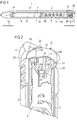
Figure 1 schematically shows a perspective sectional view of an exemplary embodiment of a drug delivery device, -
Figure 2 schematically shows a perspective sectional view of a part of the drug delivery device ofFigure 1 , -
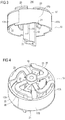
Figure 3 schematically shows a perspective side view of a part of the drug delivery device ofFigure 2 , -
Figure 4 schematically shows a perspective sectional view of the part of the drug delivery device ofFigure 3 , -
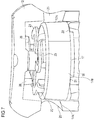
Figure 5 schematically shows a perspective sectional view of a part of the drug delivery device ofFigure 1 in an unprimed condition, -
Figure 6 schematically shows a perspective sectional view of a part of the drug delivery device ofFigure 1 in a primed condition, -
Figure 7 schematically shows a perspective sectional view of a part of the drug delivery device ofFigure 1 , -
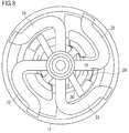
Figure 8 schematically shows a top view of the part of the drug delivery device ofFigures 3 and 4 , -
Figure 9 schematically shows a perspective sectional view of a part of the drug delivery device ofFigure 1 while switching from the unprimed condition into the primed condition. - Like elements, elements of the same kind and identically acting elements may be provided with the same reference numerals in the figures.
- In
Figure 1 , adrug delivery device 1 is shown. Thedrug delivery device 1 comprises acartridge holder 3. Thedevice 1 comprises a cartridge 4. The cartridge 4 is retained in thecartridge holder 3. Thecartridge holder 3 stabilizes the cartridge 4 mechanically. - The cartridge 4 holds a plurality of doses of a
drug 31. Thedrug 31 is preferably a liquid medication, comprising, for example, GLP-1, insulin, like short-acting or long-acting insulin, heparin or growth hormones. The term "drug", as used herein, preferably means a pharmaceutical formulation containing at least one pharmaceutically active compound,
wherein in one embodiment the pharmaceutically active compound has a molecular weight up to 1500 Da and/or is a peptide, a proteine, a polysaccharide, a vaccine, a DNA, a RNA, an enzyme, an antibody, a hormone or an oligonucleotide, or a mixture of the above-mentioned pharmaceutically active compound,
wherein in a further embodiment the pharmaceutically active compound is useful for the treatment and/or prophylaxis of diabetes mellitus or complications associated with diabetes mellitus such as diabetic retinopathy, thromboembolism disorders such as deep vein or pulmonary thromboembolism, acute coronary syndrome (ACS), angina, myocardial infarction, cancer, macular degeneration, inflammation, hay fever, atherosclerosis and/or rheumatoid arthritis,
wherein in a further embodiment the pharmaceutically active compound comprises at least one peptide for the treatment and/or prophylaxis of diabetes mellitus or complications associated with diabetes mellitus such as diabetic retinopathy,
wherein in a further embodiment the pharmaceutically active compound comprises at least one human insulin or a human insulin analogue or derivative, glucagon-like peptide (GLP-1) or an analogue or derivative thereof, or exedin-3 or exedin-4 or an analogue or derivative of exedin-3 or exedin-4. - Insulin analogues are for example Gly(A21), Arg(B31), Arg(B32) human insulin; Lys(B3), Glu(B29) human insulin; Lys(B28), Pro(B29) human insulin; Asp(B28) human insulin; human insulin, wherein proline in position B28 is replaced by Asp, Lys, Leu, Val or Ala and wherein in position B29 Lys may be replaced by Pro; Ala(B26) human insulin; Des(B28-B30) human insulin; Des(B27) human insulin and Des(B30) human insulin.
- Insulin derivates are for example B29-N-myristoyl-des(B30) human insulin; B29-N-palmitoyl-des(B30) human insulin; B29-N-myristoyl human insulin; B29-N-palmitoyl human insulin; B28-N-myristoyl LysB28ProB29 human insulin; B28-N-palmitoyl-LysB28ProB29 human insulin; B30-N-myristoyl-ThrB29LysB30 human insulin; B30-N-palmitoyl- ThrB29LysB30 human insulin; B29-N-(N-palmitoyl-Y-glutamyl)-des(B30) human insulin; B29-N-(N-lithocholyl-Y-glutamyl)-des(B30) human insulin; B29-N-(ω-carboxyheptadecanoyl)-des(B30) human insulin and B29-N-(ω-carboxyheptadecanoyl) human insulin.
- Exendin-4 for example means Exendin-4(1-39), a peptide of the sequence H-His-Gly-Glu-Gly-Thr-Phe-Thr-Ser-Asp-Leu-Ser-Lys-Gln-Met-Glu-Glu-Glu-Ala-Val-Arg-Leu-Phe-Ile-Glu-Trp-Leu-Lys-Asn-Gly-Gly-Pro-Ser-Ser-Gly-Ala-Pro-Pro-Pro-Ser-NH2.
- Exendin-4 derivatives are for example selected from the following list of compounds:
- H-(Lys)4-des Pro36, des Pro37 Exendin-4(1-39)-NH2,
- H-(Lys)5-des Pro36, des Pro37 Exendin-4(1-39)-NH2,
- des Pro36 [Asp28] Exendin-4(1-39),
- des Pro36 [IsoAsp28] Exendin-4(1-39),
- des Pro36 [Met(0)14, Asp28] Exendin-4(1-39),
- des Pro36 [Met(0)14, IsoAsp28] Exendin-4(1-39),
- des Pro36 [Trp(02)25, Asp28] Exendin-4(1-39),
- des Pro36 [Trp(02)25, IsoAsp28] Exendin-4(1-39),
- des Pro36 [Met(0)14 Trp(02)25, Asp28] Exendin-4(1-39),
- des Pro36 [Met(0)14 Trp(02)25, IsoAsp28] Exendin-4(1-39); or
- des Pro36 [Asp28] Exendin-4(1-39),
- des Pro36 [IsoAsp28] Exendin-4(1-39),
- des Pro36 [Met(0)14, Asp28] Exendin-4(1-39),
- des Pro36 [Met(0)14, IsoAsp28] Exendin-4(1-39),
- des Pro36 [Trp(02)25, Asp28] Exendin-4(1-39),
- des Pro36 [Trp(02)25, IsoAsp28] Exendin-4(1-39),
- des Pro36 [Met(0)14 Trp(02)25, Asp28] Exendin-4(1-39),
- des Pro36 [Met(0)14 Trp(02)25, IsoAsp28] Exendin-4(1-39),
- wherein the group -Lys6-NH2 may be bound to the C-terminus of the Exendin-4 derivative;
- or an Exendin-4 derivative of the sequence
- H-(Lys)6-des Pro36 [Asp28] Exendin-4(1-39)-Lys6-NH2,
- des Asp28 Pro36, Pro37, Pro38Exendin-4(1-39)-NH2,
- H-(Lys)6-des Pro36, Pro38 [Asp28] Exendin-4(1-39)-NH2,
- H-Asn-(Glu)5des Pro36, Pro37, Pro38 [Asp28] Exendin-4(1-39)-NH2,
- des Pro36, Pro37, Pro38 [Asp28] Exendin-4(1-39)-(Lys)6-NH2,
- H-(Lys)6-des Pro36, Pro37, Pro38 [Asp28] Exendin-4(1-39)-(Lys)6-NH2,
- H-Asn-(Glu)5-des Pro36, Pro37, Pro38 [Asp28] Exendin-4(1-39)-(Lys)6-NH2,
- H-(Lys)6-des Pro36 [Trp(02)25, Asp28] Exendin-4(1-39)-Lys6-NH2,
- H-des Asp28 Pro36, Pro37, Pro38 [Trp(02)25] Exendin-4(1-39)-NH2,
- H-(Lys)6-des Pro36, Pro37, Pro38 [Trp(02)25, Asp28] Exendin-4(1-39)-NH2,
- H-Asn-(Glu)5-des Pro36, Pro37, Pro38 [Trp(02)25, Asp28] Exendin-4(1-39)-NH2,
- des Pro36, Pro37, Pro38 [Trp(02)25, Asp28] Exendin-4(1-39)-(Lys)6-NH2,
- H-(Lys)6-des Pro36, Pro37, Pro38 [Trp(02)25, Asp28] Exendin-4(1-39)-(Lys)6-NH2,
- H-Asn-(Glu)5-des Pro36, Pro37, Pro38 [Trp(02)25, Asp28] Exendin-4(1-39)-(Lys)6-NH2,
- H-(Lys)6-des Pro36 [Met(0)14, Asp28] Exendin-4(1-39)-Lys6-NH2,
- des Met(0)14 Asp28 Pro36, Pro37, Pro38 Exendin-4(1-39)-NH2,
- H-(Lys)6-desPro36, Pro37, Pro38 [Met(O)14, Asp28] Exendin-4(1-39)-NH2,
- H-Asn-(Glu)5-des Pro36, Pro37, Pro38 [Met(0)14, Asp28] Exendin-4(1-39)-NH2,
- des Pro36, Pro37, Pro38 [Met(0)14, Asp28] Exendin-4(1-39)-(Lys)6-NH2,
- H-(Lys)6-des Pro36, Pro37, Pro38 [Met(0)14, Asp28] Exendin-4(1-39)-(Lys)6-NH2,
- H-Asn-(Glu)5 des Pro36, Pro37, Pro38 [Met(0)14, Asp28] Exendin-4(1-39)-(Lys)6-NH2,
- H-Lys6-des Pro36 [Met(0)14, Trp(02)25, Asp28] Exendin-4(1-39)-Lys6-NH2,
- H-des Asp28 Pro36, Pro37, Pro38 [Met(0)14, Trp(02)25] Exendin-4(1-39)-NH2,
- H-(Lys)6-des Pro36, Pro37, Pro38 [Met(0)14, Asp28] Exendin-4(1-39)-NH2,
- H-Asn-(Glu)5-des Pro36, Pro37, Pro38 [Met(0)14, Trp(02)25, Asp28] Exendin-4(1-39)-NH2,
- des Pro36, Pro37, Pro38 [Met(0)14, Trp(02)25, Asp28] Exendin-4(1-39)-(Lys)6-NH2,
- H-(Lys)6-des Pro36, Pro37, Pro38 [Met(0)14, Trp(02)25, Asp28] Exendin-4(S1-39)-(Lys)6-NH2,
- H-Asn-(Glu)5-des Pro36, Pro37, Pro38 [Met(0)14, Trp(02)25, Asp28] Exendin-4(1-39)-(Lys)6-NH2;
- Hormones are for example hypophysis hormones or hypothalamus hormones or regulatory active peptides and their antagonists as listed in Rote Liste, ed. 2008, Chapter 50, such as Gonadotropine (Follitropin, Lutropin, Choriongonadotropin, Menotropin), Somatropine (Somatropin), Desmopressin, Terlipressin, Gonadorelin, Triptorelin, Leuprorelin, Buserelin, Nafarelin, Goserelin.
- A polysaccharide is for example a glucosaminoglycane, a hyaluronic acid, a heparin, a low molecular weight heparin or an ultra low molecular weight heparin or a derivative thereof, or a sulphated, e.g. a poly-sulphated form of the above-mentioned polysaccharides, and/or a pharmaceutically acceptable salt thereof. An example of a pharmaceutically acceptable salt of a poly-sulphated low molecular weight heparin is enoxaparin sodium.
- Pharmaceutically acceptable salts are for example acid addition salts and basic salts. Acid addition salts are e.g. HCl or HBr salts. Basic salts are e.g. salts having a cation selected from alkali or alkaline, e.g. Na+, or K+, or Ca2+, or an ammonium ion N+(R1)(R2)(R3)(R4), wherein R1 to R4 independently of each other mean: hydrogen, an optionally substituted C1-C6-alkyl group, an optionally substituted C2-C6-alkenyl group, an optionally substituted C6-C10-aryl group, or an optionally substituted C6-C10-heteroaryl group. Further examples of pharmaceutically acceptable salts are described in "Remington's Pharmaceutical Sciences" 17. ed. Alfonso R. Gennaro (Ed.), Mark Publishing Company, Easton, Pa., U.S.A., 1985 and in Encyclopedia of Pharmaceutical Technology.
- Pharmaceutically acceptable solvates are for example hydrates.
- The cartridge 4 has an
outlet 5. Thedrug 31 can be dispensed from the cartridge 4 through theoutlet 5. Thedevice 1 comprises acap 14 which protects the cartridge 4 against external influences. - The
drug delivery device 1 may be an injection device. Thedrug delivery device 1 may be a pen-type device, in particular a pen-type injector. Thedevice 1 may be a disposable or a re-usable device. Preferably, thedevice 1 is a fixed dose device, in particular a device configured to dispense doses of thedrug 31 which may not be varied by the user. Alternatively, thedevice 1 may be configured to dispense variable, preferably user-settable, doses of thedrug 31. Thedrug delivery device 1 may be a manually, in particular a non-electrically, driven device. - The
drug delivery device 1 comprises ahousing 2. Thedrug delivery device 1 and thehousing 2 have a distal end and a proximal end. The term "distal end" designates that end of thedrug delivery device 1 or a component thereof which is or is to be arranged closest to a dispensing end of thedrug delivery device 1. The distal end of thedevice 1 is indicated byarrow 15. The term "proximal end" designates that end of thedevice 1 or a component thereof which is or is to be arranged furthest away from the dispensing end of thedevice 1. The proximal end of thedevice 1 is indicated byarrow 16. - The
drug delivery device 1 comprises abung 7. Thebung 7 is retained in the cartridge 4. Thebung 7 is moveable with respect to the cartridge 4. Thebung 7 seals the cartridge 4 proximally. Movement of thebung 7 in the distal direction with respect to the cartridge 4 causes thedrug 31 to be dispensed from the cartridge 4 through theoutlet 5. - The
device 1 comprises apiston rod 8. Thepiston rod 8 operates through thehousing 2 of thedrug delivery device 1. Thepiston rod 8 is rotatable in a delivery direction with respect to thehousing 8 for delivering a dose. Thepiston rod 8 is designed to transfer axial movement through thedrug delivery device 1, for example for the purpose of dispensing thedrug 31. In particular, thepiston rod 8 is designed to transfer force to thebung 7, thereby pushing thebung 7 in the distal direction with respect to the cartridge 4. In this way, a dose of thedrug 31 is dispensed from the cartridge 4. The size of the dispensed dose is determined by the distance by which thebung 7 is displaced in the distal direction with respect to the cartridge 4. - The
device 1 comprises a drive mechanism. The drive mechanism is arranged within thehousing 2 of thedrug delivery device 1. The drive mechanism comprises adose button 12. Thedose button 12 may comprise or may be embodied as a sleeve. Thedose button 12 is moveable with respect to thehousing 2. Preferably, thedose button 12 is splined to thehousing 2. Thedose button 12 is moveable in the proximal direction with respect to thehousing 2 for setting a dose of thedrug 31. Thedose button 12 is moveable in the distal direction with respect to thehousing 2 for delivering the dose of thedrug 31. - The distance by which the
dose button 12 is moved proximally with respect to thehousing 2 for setting the dose of thedrug 31 may determine the size of the dose. A proximal end position and a distal end position of thedose button 12 with respect to thehousing 2 is determined by a respective stop feature (not explicitly shown) limiting the proximal or distal movement of thedose button 12 with respect to thehousing 2. - The drive mechanism comprises a
drive member 11. Thedrive member 11 may comprise or may be embodied as a sleeve. Thedrive member 11 is axially moveable with respect to thehousing 2. Thedrive member 11 is prevented from rotating with respect to thehousing 11. Thedrive member 11 is secured against movement with respect to thedose button 12. Axial movement of thedose button 12 is converted into axial movement of thedrive member 11 with respect to thehousing 2. - A user-applied force causing the
dose button 12 to be moved distally with respect to thehousing 2 is transferred to thepiston rod 8 by the drive mechanism for dispensing the dose (seeFigures 1 and9 ). Thepiston rod 8 comprises athread 9B.Thread 9B is arranged in the proximal end section of thepiston rod 8.Thread 9B is formed on flexible arms of the piston rod 8 (seearms Figure 9 ). Thedrive member 11 comprises amating thread 11A.Thread 11A is arranged at an inner surface of thedrive member 11.Thread 11A comprises a ramp on one side. Due to mechanical cooperation ofthread 9B andmating thread 11A axial movement of thedrive member 11 is converted into rotation of thepiston rod 8 in the delivery direction for dispensing a dose of thedrug 31. The rotation axis is a main longitudinal axis of thehousing 2 or thedevice 1. Preferably, the rotation axis runs along thepiston rod 8 and, in particular, along a main direction of extent of thepiston rod 8. - The
piston rod 8 comprises afurther thread 9A. Due to mechanical cooperation ofthread 9A and a mating thread of a further component of the drive mechanism (not explicitly shown), thepiston rod 8 travels in the distal direction with respect to thehousing 2 for dispensing the dose of thedrug 31. Thereby, from dispensing of a prime dose, which is explained later on in more detail, to dispensing of a last dose of thedrug 31 held in the cartridge 4, thepiston rod 8 travels distally with respect to thehousing 2 away from a proximal start position and towards a distal end position for delivering thedrug 31. - In an initial state of the
device 1, e.g. an unprimed condition of thedevice 1, there is agap 33 between thepiston rod 8 and thebung 7, as indicated inFigure 1 . Thegap 33 arises from manufacturing or assembly tolerances. The size of thegap 33 may vary. However, when delivering thedrug 31, thegap 33 between thepiston rod 8 and thebung 7 reduces the dose accuracy, because thepiston rod 8 has to close thegap 33 before thebung 7 is advanced anddrug 31 is expelled. - In order to reduce, in particular to remove, the
gap 33, thedevice 1 has to be primed. For priming thedevice 1, often, a minimum dose of thedrug 31, e.g. a prime dose, is set and dispensed from the cartridge 4. While dispensing the prime dose, the distance between thepiston rod 8 and thebung 7 is removed and a small amount of thedrug 31 is delivered from the cartridge 4. Afterwards, thepiston rod 8 abuts thebung 7, i.e. thegap 33 between thepiston rod 8 and thebung 7 was removed. After having removed thegap 33, thedevice 1 is ready for setting and delivering a first dose of thedrug 31 to the user. - Often, it is difficult for the user to realize whether the
device 1 was primed or not, i.e. whether thedevice 1 is ready to deliver the first dose. However, it is crucial for the user to know whether thedevice 1 has been primed or not, as if the user erroneously primes thedevice 1 although its has already been primed, the user may waste a dose of thedrug 31. On the other hand, if the user dispenses the first dose, believing that thedevice 1 has already been primed, he may inject an underdose, which may have fatal, or even lethal consequences for the user. - In order to distinguish the primed
device 1, which is ready for setting and delivering the first dose to the user, from theunprimed device 1, e.g. in order to indicate if the prime dose has been dispended or not, thedevice 1 comprises an indicator 13 (see in particularFigures 2 to 4 ). Theindicator 13 is a prime status indicator. Theindicator 13 is adapted to indicate two different operation conditions, namely the primed condition (seeFigure 6 ) and the unprimed condition (seeFigure 5 ), of thedevice 1. - The
indicator 13 is arranged in the proximal end section of thedevice 1. Theindicator 13 is retained in thedose button 12. Theindicator 13 is rotatable with respect to thedose button 12 in a limited fashion. Theindicator 13 is secured against proximal displacement with respect to thedose button 12 and, hence, with respect to thedrive member 11, by means of mechanical cooperation, in particular abutment, of a proximal end face of theindicator 13 with a proximalinner face 30 of the dose button 12 (seeFigure 2 ). Theindicator 13 is secured against distal displacement with respect to thedose button 12 and, hence, with respect to thedrive member 11, by mechanical cooperation, in particular abutment, of a distal end face of theindicator 13 with a proximal end face of thedrive member 11. - The
indicator 13 is configured to mechanically cooperate with thepiston rod 8 when thedevice 1 is primed, in particular when the prime dose is dispensed. When thepiston rod 8 is rotated in the delivery direction with respect to thehousing 2 for dispensing the prime dose, thepiston rod 8 interacts with theindicator 13 such that theindicator 13 follows, in a limited fashion, rotation of thepiston rod 8 in the delivery direction. - The
indicator 13 comprises aninner member 18, as shown inFigure 2 , for example. Theinner member 18 is adapted to cooperate with thepiston rod 8. Theindicator 13 comprises an outer indication element 17 (seeFigure 2 and alsoFigures 3 and 4 ). Theouter indication element 17 is radially offset from theinner member 18. In particular, an outer surface, e.g. anindication surface outer indication element 17 is arranged closer to the inner surface of thedose button 12, than an outer surface of theinner member 18. Theinner member 18 reaches further in the proximal direction with respect to thehousing 2 than theouter indication element 17 in order to allow mechanical cooperation of theinner member 17 with thepiston rod 8. Theinner member 18 is partly arranged inside theouter indication element 17. Theouter indication element 17 may comprise or may be embodied as an outer ring. Theinner member 18 may comprise or may be embodied as a central hub. - The
outer indication element 17 is slightly axially moveable with respect to theinner member 18 while dispensing the prime dose, which is explained in connection withFigures 5 and 6 in more detail. Theouter indication element 17 is resiliently connected to theinner member 18 by means of a plurality of flexible members 23 (seeFigures 3 and 4 ). The respectiveflexible member 23 is a flexible web. Theflexible members 23, theinner member 18 and theouter indication element 17 are formed unitarily. - The
flexible members 23 are secured to the proximal end face of theouter indication element 17 and theinner member 18. In particular, theflexible members 23 resiliently connect the proximal end face of theinner member 18 with the proximal end face of theouter indication element 17. Theflexible members 23 extend in the radial direction with respect to thehousing 2. Theflexible members 23 are shaped s-like. This may help to increase flexibility of theflexible members 23 and, hence, may reduce the force the user must apply to rotate theindicator 13, e.g. when priming thedevice 1. Hence, a user-friendlydrug delivery device 1 is achieved. - When the
device 1 is assembled, in particular when thedose button 12 is assembled over theindicator 13, thedose button 12 forces theinner member 18 in the distal direction with respect to thehousing 2, thereby deforming theflexible members 23. This deformation tends to bias theouter indication element 17 in the distal direction with respect to thehousing 2 and distally onto thedrive member 11, which is explained later on in more detail. - The
inner member 18 comprises afirst interaction surface 20. Thefirst interaction surface 20 is arranged in the distal end section of theinner member 18. Thefirst interaction surface 20 protrudes radially outwardly from theinner member 18. Thefirst interaction surface 20 and theinner member 18 are unitarily formed. - When the
piston rod 8 is rotated for dispensing the prime dose, thepiston rod 8, in particular theflexible arm 32A (seeFigure 9 ) of thepiston rod 8, is moved towards thefirst interaction surface 20 until theflexible arm 32A abuts thefirst interaction surface 20. When thepiston rod 8 is rotated further in the delivery direction with respect to thehousing 2, theflexible arm 32A applies force onto thefirst interaction surface 20 and, hence, onto theindicator 13. Consequently, thepiston rod 8 rotates theindicator 13 in the delivery direction with respect to thehousing 2, thus switching theindicator 13 from a first indication position, e.g. the position of theindicator 13 when thedevice 1 is in the unprimed condition, into a second indication position, e.g. the position of theindicator 13 when thedevice 1 is in the primed condition. - For indicating the different operation conditions, e.g. the primed condition and the unprimed condition of the
device 1, theouter indication element 17 provides two first indication surfaces 17A. Theouter indication element 17 provides two second indication surfaces 17B. Therespective indication surfaces first indication surface 17A may comprise a different colour compared to the second indication surfaces 17A. Preferably, the first indication surfaces 17A comprise an orange or red colour for indicating that thedevice 1 is unprimed. The second indication surfaces 17A may comprise a green or white colour, for indicating that thedevice 1 has been primed. - The two first indication surfaces 17 are disposed oppositely. The two second indication surfaces 17B are disposed oppositely. The
dose button 12 comprises twoapertures 25. The twoapertures 25 are disposed oppositely. Theapertures 25 axially overlap with theouter indication element 17, in particular the respective indication surfaces 17A, 17B. - In the first indication position, e.g. when the
device 1 is in the unprimed condition, a respectivefirst indication surface 17A is visible through arespective aperture 25. When theindicator 13 and, hence, theouter indication element 17 was rotated into the second indication position, e.g. when thedevice 1 was switched into the primed condition due to dispensing the prime dose, a respectivesecond interaction surface 17B is visible through arespective aperture 25. In this way, the user easily recognizes in which operation condition thedevice 1 is, irrespective of the position of thedevice 1 with respect to the user. Hence, a very user-friendly and safedrug delivery device 1 is achieved. - When the
device 1 is unprimed, i.e. when theindicator 13 is in the first indication position, externally applied forces, such as those generated by vibration, impact or user tampering, may cause theindicator 13 to be unintentionally rotated into the second indication position such that the first indication surfaces 17A, e.g. the orange surfaces, move out of view and such that the user is erroneously indicated that thedevice 1 has been primed. In order to prevent that theindicator 13 is rotated in the second indication position without having primed the device, which may have fatal consequences for the user, theinner member 18 comprises asecond interaction surface 19. - The
second interaction surface 19 and theinner member 18 are formed unitarily. Thesecond interaction surface 19 is part of a rib. Thesecond interaction surface 19 is arranged closer to the proximal end section of theinner member 18 than thefirst interaction surface 20. This facilitates interaction of thepiston rod 8 and theinner member 18, when thedevice 1 is in the initial state, i.e. when thepiston rod 8 is in the proximal start position. - The
second interaction surface 19 has a smaller angular distance with respect to thepiston rod 8, in particular with respect to theflexible arm 32B of the piston rod 8 (seeFigure 2 and, in particular,arrow 29 inFigure 8 ), than thefirst interaction surface 20 has with respect to theflexible arm 32A when thedevice 1 is in the initial state. Preferably, theindicator 13 is splined to thepiston rod 8 by mechanical cooperation of thesecond interaction surface 19 and theflexible arm 32B. Mechanical cooperation of thesecond interaction surface 19 and theflexible arm 32B prevents unintentional rotation of theindicator 13 and, hence, of theouter indication element 17 in the delivery direction and, hence, into the second indication position when thedevice 1 is in the initial state. In other words, theindicator 13 is kept in the first indication position by means of mechanical cooperation ofinteraction surface 19 and thepiston rod 8. Furthermore, for keeping theindicator 13 in the first or in the second indication position, theouter indication element 17 comprises twofirst detents 21, as shown inFigure 5 . The respectivefirst detent 21 is an indentation. Theouter indication element 17 comprises twosecond detents 22, as shown inFigure 6 . The respectivesecond detent 22 is an indentation. Therespective detents outer indication element 17. - The two
first detents 21 are disposed oppositely. The twosecond detents 22 are disposed oppositely. Thefirst detents 21 and thesecond detents 22 are unitarily formed with theouter indication element 17. Preferably, thedetents outer indication element 17. - The
device 1 comprises two counter elements 24. The counter elements 24 are part of thedrive member 11. The counter elements 24 are disposed oppositely. Thedrive member 11 and the counter elements 24 are unitarily formed. The respective counter element 24 is a protrusion, protruding from thedrive member 11 in the proximal direction with respect to thehousing 2. - The respective counter element 24 engages with one
respective detent outer indication element 17 and, hence, theindicator 13 in one respective indication position. In other words, in the first indication position, e.g. in the unprimed position, the respective counter element 24 is engaged with the respectivefirst detent 21. In the second indication position, e.g. in the primed position, the respective counter element 24 is engaged with the respectivesecond detent 22. In particular, when the counter elements 24 are engaged with thefirst detents 21, thesecond detents 22 are disengaged and vice versa. - The
first detents 21 comprise a ramp. The ramp rises in the rotational direction of thepiston rod 8, i.e. the delivery direction. The ramp is adapted to releasably secure theindicator 13 in the first indication position. The ramp reduces the torque needed to rotate theindicator 13 in the delivery direction and out of engagement with the counter elements 24 while dispensing the prime dose. When theindicator 13 is rotated in the delivery direction, the counter elements 24 slide along the ramp, thus being brought out of engagement with thedetents 21. - The
flexible members 23 secured to the proximal end face of theindication element 17 allow theouter indication element 17 to ride up over thefirst detents 21. In other words, theflexible members 23 allow slight proximal movement of theouter indication element 17 for disengaging with the counter elements 24 while dispensing the prime dose, in particular while switching theindicator 13 from the first indication position into the second indication position. Theflexible members 23 force theouter indication element 17, in particular thesecond detents 22, into cooperation with the counter elements 24 when the prime dose was dispensed. - The
second detents 22 do not comprise a ramp but comprise side faces which run parallel to the main longitudinal axis of thehousing 2. This helps to prevent rotation of theindicator 13 from the second indication position back into the first indication position. In this way, thesecond detents 22 facilitate irreleasably securing theindicator 13 in the second indication position while thepiston rod 8 travels towards the distal end position when delivering thedrug 31 to the user after thedevice 1 was primed. - In order to help preventing movement of the
indicator 13 from the second indication position back into the first indication position, thedose button 12 comprises a plurality ofprotrusions 26, which are indicated inFigure 7 . The protrusions are ramp-shaped, the ramps rising in the delivery direction. Theprotrusions 26 are arranged inside thedose button 12. Theprotrusions 26 are arranged at the proximalinner face 30 of thedose button 12. Theprotrusions 26 are axially aligned with the middle of outer surfaces of theflexible members 23 when the counter element 24 is engaged with thefirst detents 21 or with thesecond detents 22. - When an external force is applied to bring the counter element 24 out of engagement with the
second detents 22, e.g. when theouter indication element 17 is slightly displaced proximally with respect to theinner member 18, the middle of theflexible members 23 abuts theprotrusions 26. In this way, the effective length over which theflexible members 23 are bent is reduced and, hence, proximal displacement of theouter indication element 17 to bring thesecond detents 22 out of engagement with the counter element 24 is minimized or even prevented. Hence, theindicator 13 is effectively prevented from switching from the second indication position back into the first indication position. - Accordingly, the
protrusions 26 act for preventing rotation of theindicator 13 in a direction opposite to the delivery direction to unintentionally switch theindicator 13 from the first indication position into the second indication position. However, as theprotrusions 26 are ramp-shaped in the delivery direction, proximal displacement of theouter indication element 17 to bring thefirst detents 21 out of engagement with the counter elements 24 for switching theindicator 13 from the first indication position into the second indication position is not prevented, when theindicator 13 is rotated in the delivery direction. - In the following, the operation of priming the
device 1 is described, as shown inFigure 9 : - The user pulls the
dose button 12 proximally for setting the prime dose. Proximal movement of thedose button 12 is converted into proximal movement of thedrive member 11 with respect to thehousing 2. Theindicator 13 moves proximally together with thedose button 12 and thedrive sleeve 11. - After the prime dose has been set, the user pushes the
dose button 12 and, hence, thedrive member 11 distally. Thereby, theindicator 13 is moved distally such that thefirst interaction surface 20 axially overlaps with theflexible arm 32A of thepiston rod 8. Distal movement of thedrive member 11 is converted into distal and rotational movement of thepiston rod 8 in the delivery direction with respect to thehousing 2. - The
flexible arm 32A abuts thefirst interaction surface 20 and, thus, rotation of thepiston rod 8 is converted into rotation of theindicator 13 in the delivery direction (seearrow 28 inFigure 9 ), the ramp of the primeddetents 21 thereby raising theouter indication element 17 out of engagement with the counter elements 24, as described previously. The first indication surfaces 17A are rotated out of theapertures 25 and thesecond indication surface 17B are rotated into theapertures 25. - The
outer indication element 17 is biased distally by means of theflexible members 23 and, hence, when thesecond detents 22 have reached the counter elements 24, thesecond detents 22 get engaged with the counter elements 24, preventing further rotation of theindicator 13 which would switch theindicator 13 from the second indication position back into the first indication position. Now, thedevice 1 is in the primed condition and theindicator 13 is irreleasably secured in the second indication position. - Accordingly, the user is indicated that the
device 1 has been primed and hence, that thedevice 1 is ready for setting and dispensing the first dose of thedrug 31. When the first dose is set, thefirst interaction surface 20 disengages with theflexible arm 32A. Hence, mechanical cooperation of thepiston rod 8 and theindicator 13 is prevented when thepiston rod 8 travels towards the distal end position for dispensing thedrug 31. Setting and dispensing a dose of thedrug 31 may occur in the same way as described for setting and dispensing the prime dose. - The
device 1 described above provides clear visual signals indicating to the user whether thedevice 1 has been primed or not. As the signal is binary, it is very difficult to misinterpret it. Hence, a user-friendly and easily handleddrug delivery device 1 is achieved. Due to the shape of theflexible members 23, thedevice 1 minimizes the force required for priming thedevice 1, which is especially useful for users with limited mobility. The above describedindicator 13 is an easy to manufacture component and hence, a very cost-effectivedrug delivery device 1 is achieved. - Other implementations are within the scope of the following claims. Elements of different implementations may be combined to form implementations not specifically described herein.
-
- 1
- Drug delivery device
- 2
- Housing
- 3
- Cartridge holder
- 4
- Cartridge
- 5
- Outlet
- 7
- Bung
- 8
- Piston rod
- 9A
- Thread
- 9B
- Thread
- 11
- Drive member
- 11A
- Thread
- 12
- Dose button
- 13
- Indicator
- 14
- Cap
- 15
- Distal end
- 16
- Proximal end
- 17
- Outer indication element
- 17A
- First indication surface
- 17B
- Second indication surface
- 18
- Inner member
- 19
- First interaction surface
- 20
- Second interaction surface
- 21
- First detent
- 22
- Second detent
- 23
- Flexible member
- 24
- Counter element
- 25
- Aperture
- 26
- Protrusion
- 27
- Arrow
- 28
- Arrow
- 29
- Arrow
- 30
- Inner face
- 31
- Drug
- 32A
- Flexible arm
- 32B
- Flexible arm
- 33
- Gap
Claims (16)
- An assembly for a drug delivery device (1),
comprising:- a housing (2) having a proximal end and a distal end,- a piston rod (8) which is adapted to be displaced distally with respect to the housing (2) away from a proximal start position and towards a distal end position for delivering a drug (31),- an indicator (13) for indicating at least two different operation conditions of the assembly, the indicator (13) being moveable with respect to the housing (2) from a first indication position for a first condition of the assembly into a second indication position for a second condition of the assembly, wherein- the piston rod (8) and the indicator (13) are configured to mechanically interact for converting movement of the piston rod (8) into movement of the indicator (13), and characterized by- a first detent (21) provided in the indicator (13), which is configured to releasably secure the indicator (13) in the first indication position such that movement into the second indication position is allowed, and by- a second detent (22) provided in the indicator (13), which is configured to secure the indicator (13) in the second indication position such that movement into the first indication position is prevented. - The assembly according to claim 1,
wherein the second detent (22) irreleasably secures the indicator (13) in the second indication position while the piston rod (8) travels to the distal end position. - The assembly according to claim 1 or claim 2,
wherein the piston rod (8) is rotatable in a first rotational direction with respect to the housing (2) and, wherein, the indicator (13) is arranged and configured to mechanically interact with the piston rod (8) such that the indicator (13) is at least partly rotated together with the piston rod (8) in the first rotational direction when the assembly switches from the first indication position into the second indication position. - The assembly according to claim 3,
wherein the first detent (21) comprises a ramp for releasably securing the indicator (13) in the first indication position, and, wherein, the ramp rises in the first rotational direction. - The assembly according to any of the previous claims,
wherein the indicator (13) comprises the first detent (21) and the second detent (22). - The assembly according to any of the previous claims,
comprising a drive member (11) and a dose button (12), wherein the dose button (12) is moveable with respect to the housing (2), with movement of the dose button (12) being converted into movement of the drive member (11) by mechanical interaction of dose button (12) and drive member (11), wherein movement of the dose button (12) in the distal direction with respect to the housing (2) causes transition of the indicator (13) from the first indication position into the second indication position. - The assembly according to claim 6,
comprising at least one counter element (24) for engaging the respective detent (21, 22), wherein the at least one counter element (24) is part of the drive member (11) and, wherein, when the counter element (24) engages with one of the detents (21, 22), the counter element (24) is disengaged from the other one of the detents (21,22). - The assembly according to any of the previous claims,
wherein the indicator (13) comprises an inner member (18) and an outer indication element (17), the inner member (18) and the outer indication element (17) being resiliently connected with each other such that the outer indication element (17) is moveable with respect to the inner member (18) when switching from the first indication position into the second indication position. - The assembly of claim 8,
wherein the inner member (18) is configured to cooperate with the piston rod (8) for switching from the first indication position into the second indication position and, wherein, the inner member (18) comprises at least one first interaction surface (20), wherein movement of the piston rod (8) is converted into movement of the indicator (13) by mechanical cooperation of the first interaction surface (20) and the piston rod (8). - The assembly of claim 8 or claim 9,
wherein the inner member (18) comprises at least one second interaction surface (19), with mechanical cooperation of the second interaction surface (19) and the piston rod (18) keeping the indicator (13) in the first indication position. - The assembly of claim 10,
wherein the first interaction surface (20) protrudes radially outwardly from the inner member (18) and the second interaction surface (19) is arranged closer to a proximal end of the piston rod (8) than the first interaction surface (20), and, wherein an angular distance between the second interaction surface (19) and the piston rod (8) is smaller than an angular distance between the first interaction surface (20) and the piston rod (8). - The assembly according to any of claims 8 to 11,
wherein the inner member (18) and the outer indication element (17) are connected by means of at least one flexible member (23) and, wherein, when the first detent (21) and the second detent (22) are disengaged from the counter element (24), the flexible member (23) provides a force which tends to displace the indicator element (17) in the distal direction with respect to the housing (2). - The assembly according to claim 12,
wherein the flexible member (23) is secured to an end face of the outer indication element (17), the flexible member (23) running in the radial direction with respect to the housing (2) and, wherein the flexible member (23) is shaped s-like. - The assembly according to claim 12 or 13,
wherein the dose button (12) comprises a plurality of protrusions (26) arranged on an inner surface of the dose button (12), the protrusions (26) being configured to mechanically interact with the at least one flexible member (23) such that movement of the indicator (13) away from the second indication position and back towards the first indication position is prevented. - The assembly according to any of the previous claims,
wherein the indicator (13) is configured to be a prime status indicator (13) and, wherein, the first indication position denotes an unprimed condition of the assembly and, wherein the second indication position denotes a primed condition of the assembly. - An indicator (13) for a drug delivery device (1), the indicator (13) comprising an inner member (18) and an outer indication element (17), the outer indication element (17) providing an indication surface (17A, 17B) and being resiliently connected to the inner member (18) by at least one flexible member (23), wherein the indicator (13) comprises at least one first detent (21) and at least one second detent (22), the first detent (21) being adapted to enable rotation of the indicator (13) in a first direction and the second detent (22) being adapted to prevent rotation of the indicator (13) in the direction opposite to the first direction.
Priority Applications (1)
| Application Number | Priority Date | Filing Date | Title |
|---|---|---|---|
| EP10762886.9A EP2480268B1 (en) | 2009-09-23 | 2010-09-21 | Assembly and indicator for a drug delivery device |
Applications Claiming Priority (3)
| Application Number | Priority Date | Filing Date | Title |
|---|---|---|---|
| EP09171134 | 2009-09-23 | ||
| EP10762886.9A EP2480268B1 (en) | 2009-09-23 | 2010-09-21 | Assembly and indicator for a drug delivery device |
| PCT/EP2010/063842 WO2011036134A2 (en) | 2009-09-23 | 2010-09-21 | Assembly and indicator for a drug delivery device |
Publications (2)
| Publication Number | Publication Date |
|---|---|
| EP2480268A2 EP2480268A2 (en) | 2012-08-01 |
| EP2480268B1 true EP2480268B1 (en) | 2016-08-17 |
Family
ID=41682306
Family Applications (1)
| Application Number | Title | Priority Date | Filing Date |
|---|---|---|---|
| EP10762886.9A Active EP2480268B1 (en) | 2009-09-23 | 2010-09-21 | Assembly and indicator for a drug delivery device |
Country Status (14)
| Country | Link |
|---|---|
| US (2) | US9511193B2 (en) |
| EP (1) | EP2480268B1 (en) |
| JP (1) | JP5875982B2 (en) |
| CN (1) | CN102510761B (en) |
| AU (1) | AU2010299934B2 (en) |
| BR (1) | BR112012006516B1 (en) |
| CA (1) | CA2772686C (en) |
| DK (1) | DK2480268T3 (en) |
| ES (1) | ES2603749T3 (en) |
| HK (1) | HK1173687A1 (en) |
| HU (1) | HUE031031T2 (en) |
| IL (1) | IL218493A (en) |
| PL (1) | PL2480268T3 (en) |
| WO (1) | WO2011036134A2 (en) |
Families Citing this family (40)
| Publication number | Priority date | Publication date | Assignee | Title |
|---|---|---|---|---|
| ES2314182T3 (en) | 2002-02-11 | 2009-03-16 | Antares Pharma, Inc. | INTRADERMIC INJECTOR. |
| EP1850892B2 (en) | 2005-01-24 | 2023-04-19 | Antares Pharma, Inc. | Prefilled needle assisted syringe jet injector |
| US9022980B2 (en) | 2005-02-01 | 2015-05-05 | Kaleo, Inc. | Medical injector simulation device |
| US8206360B2 (en) | 2005-02-01 | 2012-06-26 | Intelliject, Inc. | Devices, systems and methods for medicament delivery |
| NZ560516A (en) | 2005-02-01 | 2010-12-24 | Intelliject Inc | A delivery system where a medicant is automatically delivered on activation as well as a recorded instruction |
| US8231573B2 (en) | 2005-02-01 | 2012-07-31 | Intelliject, Inc. | Medicament delivery device having an electronic circuit system |
| US8361026B2 (en) | 2005-02-01 | 2013-01-29 | Intelliject, Inc. | Apparatus and methods for self-administration of vaccines and other medicaments |
| US9144648B2 (en) | 2006-05-03 | 2015-09-29 | Antares Pharma, Inc. | Injector with adjustable dosing |
| WO2007131013A1 (en) | 2006-05-03 | 2007-11-15 | Antares Pharma, Inc. | Two-stage reconstituting injector |
| WO2009114542A1 (en) | 2008-03-10 | 2009-09-17 | Antares Pharma, Inc. | Injector safety device |
| USD994111S1 (en) | 2008-05-12 | 2023-08-01 | Kaleo, Inc. | Medicament delivery device cover |
| EP2318075B1 (en) | 2008-08-05 | 2019-05-22 | Antares Pharma, Inc. | Multiple dosage injector |
| EP2408493A1 (en) | 2009-03-20 | 2012-01-25 | Antares Pharma, Inc. | Hazardous agent injection system |
| US8627816B2 (en) | 2011-02-28 | 2014-01-14 | Intelliject, Inc. | Medicament delivery device for administration of opioid antagonists including formulations for naloxone |
| US8939943B2 (en) | 2011-01-26 | 2015-01-27 | Kaleo, Inc. | Medicament delivery device for administration of opioid antagonists including formulations for naloxone |
| US9084849B2 (en) | 2011-01-26 | 2015-07-21 | Kaleo, Inc. | Medicament delivery devices for administration of a medicament within a prefilled syringe |
| US8496619B2 (en) | 2011-07-15 | 2013-07-30 | Antares Pharma, Inc. | Injection device with cammed ram assembly |
| US9220660B2 (en) | 2011-07-15 | 2015-12-29 | Antares Pharma, Inc. | Liquid-transfer adapter beveled spike |
| PT2822618T (en) | 2012-03-06 | 2024-03-04 | Antares Pharma Inc | Prefilled syringe with breakaway force feature |
| JP6457383B2 (en) | 2012-04-06 | 2019-01-23 | アンタレス・ファーマ・インコーポレーテッド | Needle-assisted jet injection of testosterone composition |
| WO2013169804A1 (en) | 2012-05-07 | 2013-11-14 | Antares Pharma, Inc. | Needle assisted jet injection device having reduced trigger force |
| US9522235B2 (en) | 2012-05-22 | 2016-12-20 | Kaleo, Inc. | Devices and methods for delivering medicaments from a multi-chamber container |
| WO2014106056A2 (en) | 2012-12-27 | 2014-07-03 | Kaleo, Inc. | Devices, systems and methods for locating and interacting with medicament delivery systems |
| ES2763633T3 (en) | 2013-02-11 | 2020-05-29 | Antares Pharma Inc | Needle assisted jet injection device having reduced firing force |
| ES2742046T3 (en) | 2013-03-11 | 2020-02-12 | Antares Pharma Inc | Dose injector with pinion system |
| WO2014165136A1 (en) | 2013-03-12 | 2014-10-09 | Antares Pharma, Inc. | Constant volume prefilled syringes and kits thereof |
| GB2511806A (en) | 2013-03-14 | 2014-09-17 | Norton Healthcare Ltd | Dispensing mechanism for a medical device |
| EP2968787B1 (en) * | 2013-03-14 | 2020-04-29 | Norton Healthcare Limited | Dispensing mechanism for a medical device |
| CA2906249C (en) * | 2013-03-14 | 2018-01-02 | Norton Healthcare Limited | Dispensing mechanism for a medical device |
| CA2906245C (en) | 2013-03-14 | 2019-04-30 | Norton Healthcare Limited | Dispensing mechanism for a medical device |
| TW201521819A (en) * | 2013-09-03 | 2015-06-16 | Sanofi Sa | Mechanism for a drug delivery device and drug delivery device comprising the mechanism |
| US9517307B2 (en) | 2014-07-18 | 2016-12-13 | Kaleo, Inc. | Devices and methods for delivering opioid antagonists including formulations for naloxone |
| EP3242698A1 (en) * | 2015-01-08 | 2017-11-15 | Novo Nordisk A/S | Drug injection device with visual end-of-contents indicator system |
| AU2016235054B2 (en) | 2015-03-24 | 2020-07-16 | Kaleo, Inc. | Devices and methods for delivering a lyophilized medicament |
| JP6830067B2 (en) | 2015-06-30 | 2021-02-17 | カレオ,インコーポレイテッド | Automatic syringe that administers medication in a prefilled syringe |
| AU2017379094B2 (en) | 2016-12-23 | 2023-08-24 | Kaleo, Inc. | Medicament delivery device and methods for delivering drugs to infants and children |
| US10332623B2 (en) | 2017-01-17 | 2019-06-25 | Kaleo, Inc. | Medicament delivery devices with wireless connectivity and event detection |
| EP3606585B1 (en) * | 2017-04-07 | 2023-08-02 | Novo Nordisk A/S | End-of-content mechanism |
| US11929160B2 (en) | 2018-07-16 | 2024-03-12 | Kaleo, Inc. | Medicament delivery devices with wireless connectivity and compliance detection |
| CA3145580A1 (en) | 2019-08-09 | 2021-02-18 | Kaleo, Inc. | Devices and methods for delivery of substances within a prefilled syringe |
Family Cites Families (49)
| Publication number | Priority date | Publication date | Assignee | Title |
|---|---|---|---|---|
| US533575A (en) | 1895-02-05 | wilkens | ||
| US2695023A (en) * | 1952-01-04 | 1954-11-23 | Pfizer & Co C | Hypodermic syringe |
| CH548212A (en) * | 1972-08-03 | 1974-04-30 | Compaselect Gmbh | INJECTION SYRINGE. |
| DE3715340C2 (en) * | 1987-05-08 | 1995-10-19 | Haselmeier Wilhelm Fa | Injection device |
| DK166948B1 (en) * | 1988-02-10 | 1993-08-09 | Dcp Af 1988 As | DOSING UNIT FOR DOSING A NUMBER OF MEASURED QUANTITIES OF A FLUID, SUCH AS INSULIN, FROM A GLASS STUBLE |
| US4973318A (en) * | 1988-02-10 | 1990-11-27 | D.C.P. Af 1988 A/S | Disposable syringe |
| US5226895A (en) | 1989-06-05 | 1993-07-13 | Eli Lilly And Company | Multiple dose injection pen |
| GB9007113D0 (en) | 1990-03-29 | 1990-05-30 | Sams Bernard | Dispensing device |
| ES2074771T3 (en) | 1991-07-24 | 1995-09-16 | Medico Dev Investment Co | INJECTOR. |
| DK175491D0 (en) | 1991-10-18 | 1991-10-18 | Novo Nordisk As | APPARATUS |
| US5279586A (en) | 1992-02-04 | 1994-01-18 | Becton, Dickinson And Company | Reusable medication delivery pen |
| US5391157A (en) * | 1992-10-20 | 1995-02-21 | Eli Lilly And Company | End of dose indicator |
| US5320609A (en) | 1992-12-07 | 1994-06-14 | Habley Medical Technology Corporation | Automatic pharmaceutical dispensing syringe |
| US5383865A (en) | 1993-03-15 | 1995-01-24 | Eli Lilly And Company | Medication dispensing device |
| ZA941881B (en) | 1993-04-02 | 1995-09-18 | Lilly Co Eli | Manifold medication injection apparatus and method |
| US5582598A (en) | 1994-09-19 | 1996-12-10 | Becton Dickinson And Company | Medication delivery pen with variable increment dose scale |
| JPH10510450A (en) * | 1994-12-02 | 1998-10-13 | サイエンス インコーポレイテッド | Drug dispensing device |
| US6030363A (en) * | 1994-12-02 | 2000-02-29 | Science Incorporated | Medicament dispenser |
| CA2213682C (en) | 1995-03-07 | 2009-10-06 | Eli Lilly And Company | Recyclable medication dispensing device |
| US5674204A (en) | 1995-09-19 | 1997-10-07 | Becton Dickinson And Company | Medication delivery pen cap actuated dose delivery clutch |
| US5688251A (en) | 1995-09-19 | 1997-11-18 | Becton Dickinson And Company | Cartridge loading and priming mechanism for a pen injector |
| US6110149A (en) | 1996-09-13 | 2000-08-29 | Novo Nordisk A/S | Syringe |
| DE19730999C1 (en) | 1997-07-18 | 1998-12-10 | Disetronic Licensing Ag | Injection pen dosing selected volume of fluid, especially insulin |
| US5957896A (en) | 1997-08-11 | 1999-09-28 | Becton, Dickinson And Company | Medication delivery pen |
| EP1003581B1 (en) | 1998-01-30 | 2000-11-08 | Novo Nordisk A/S | An injection syringe |
| US5961495A (en) | 1998-02-20 | 1999-10-05 | Becton, Dickinson And Company | Medication delivery pen having a priming mechanism |
| US6221053B1 (en) | 1998-02-20 | 2001-04-24 | Becton, Dickinson And Company | Multi-featured medication delivery pen |
| US6248095B1 (en) | 1998-02-23 | 2001-06-19 | Becton, Dickinson And Company | Low-cost medication delivery pen |
| JP2000070368A (en) * | 1998-08-27 | 2000-03-07 | Shimadzu Corp | Needle-less syringe |
| AU6892100A (en) | 1999-08-05 | 2001-03-05 | Becton Dickinson & Company | Medication delivery pen |
| GB0002095D0 (en) * | 2000-01-28 | 2000-03-22 | Novartis Ag | Device |
| GB0007071D0 (en) | 2000-03-24 | 2000-05-17 | Sams Bernard | One-way clutch mechanisms and injector devices |
| US6663602B2 (en) | 2000-06-16 | 2003-12-16 | Novo Nordisk A/S | Injection device |
| US6899699B2 (en) | 2001-01-05 | 2005-05-31 | Novo Nordisk A/S | Automatic injection device with reset feature |
| EP2258425B1 (en) | 2001-05-16 | 2013-01-30 | Eli Lilly and Company | Medication injector apparatus |
| GB0200444D0 (en) * | 2002-01-10 | 2002-02-27 | Owen Mumford Ltd | Improvements relating to medical injection devices |
| JP2005532129A (en) | 2002-07-10 | 2005-10-27 | ノボ・ノルデイスク・エー/エス | Syringe with dose setting limiter |
| DE10232412A1 (en) * | 2002-07-17 | 2004-02-05 | Disetronic Licensing Ag | Administration device with priming function |
| EP1542744B1 (en) * | 2002-09-24 | 2009-06-24 | SHL Group AB | Injecting device |
| GB0304823D0 (en) | 2003-03-03 | 2003-04-09 | Dca Internat Ltd | Improvements in and relating to a pen-type injector |
| GB2410188B (en) * | 2004-01-23 | 2006-01-25 | Medical House Plc | Injection device |
| PT1732628E (en) * | 2004-03-30 | 2011-12-07 | Lilly Co Eli | Medication dispensing apparatus with gear set having drive member accommodating opening |
| PL1732629T3 (en) * | 2004-03-30 | 2019-10-31 | Lilly Co Eli | Medication dispensing apparatus with spring-driven locking feature enabled by administration of final dose |
| DE102004063644A1 (en) | 2004-12-31 | 2006-07-20 | Tecpharma Licensing Ag | Device for the dosed administration of a fluid product with torsion spring drive |
| US7959607B2 (en) | 2005-05-27 | 2011-06-14 | Stryker Corporation | Hand-held fluid delivery device with sensors to determine fluid pressure and volume of fluid delivered to intervertebral discs during discography |
| US7304603B2 (en) | 2006-02-17 | 2007-12-04 | Science, Engineering And Technology Associates Corporation | Radar apparatus and processing method for detecting human carried explosive devices |
| EP2076302A1 (en) | 2006-09-15 | 2009-07-08 | TecPharma Licensing AG | Injection device with an automatically resettable dose limitation unit |
| MX2009013639A (en) * | 2007-06-12 | 2010-04-30 | Becton Dickinson Co | Syringe with disabling mechanism. |
| US8647309B2 (en) * | 2008-05-02 | 2014-02-11 | Sanofi-Aventis Deutschland Gmbh | Medication delivery device |
-
2010
- 2010-09-21 CA CA2772686A patent/CA2772686C/en active Active
- 2010-09-21 ES ES10762886.9T patent/ES2603749T3/en active Active
- 2010-09-21 JP JP2012530238A patent/JP5875982B2/en active Active
- 2010-09-21 EP EP10762886.9A patent/EP2480268B1/en active Active
- 2010-09-21 BR BR112012006516A patent/BR112012006516B1/en active IP Right Grant
- 2010-09-21 AU AU2010299934A patent/AU2010299934B2/en active Active
- 2010-09-21 PL PL10762886T patent/PL2480268T3/en unknown
- 2010-09-21 WO PCT/EP2010/063842 patent/WO2011036134A2/en active Application Filing
- 2010-09-21 US US13/392,882 patent/US9511193B2/en active Active
- 2010-09-21 DK DK10762886.9T patent/DK2480268T3/en active
- 2010-09-21 HU HUE10762886A patent/HUE031031T2/en unknown
- 2010-09-21 CN CN201080042506.9A patent/CN102510761B/en active Active
-
2012
- 2012-03-05 IL IL218493A patent/IL218493A/en active IP Right Grant
-
2013
- 2013-01-25 HK HK13101127.9A patent/HK1173687A1/en unknown
-
2016
- 2016-11-01 US US15/340,037 patent/US10413678B2/en active Active
Also Published As
| Publication number | Publication date |
|---|---|
| JP5875982B2 (en) | 2016-03-02 |
| HK1173687A1 (en) | 2013-05-24 |
| CA2772686C (en) | 2018-01-02 |
| AU2010299934A1 (en) | 2012-04-12 |
| BR112012006516B1 (en) | 2019-12-31 |
| WO2011036134A3 (en) | 2011-06-23 |
| DK2480268T3 (en) | 2016-12-12 |
| JP2013505094A (en) | 2013-02-14 |
| IL218493A0 (en) | 2012-04-30 |
| US20170043099A1 (en) | 2017-02-16 |
| EP2480268A2 (en) | 2012-08-01 |
| IL218493A (en) | 2014-07-31 |
| US9511193B2 (en) | 2016-12-06 |
| ES2603749T3 (en) | 2017-03-01 |
| WO2011036134A2 (en) | 2011-03-31 |
| US10413678B2 (en) | 2019-09-17 |
| US20120271243A1 (en) | 2012-10-25 |
| AU2010299934B2 (en) | 2014-08-14 |
| BR112012006516A2 (en) | 2016-04-26 |
| CN102510761B (en) | 2014-07-16 |
| CN102510761A (en) | 2012-06-20 |
| HUE031031T2 (en) | 2017-06-28 |
| CA2772686A1 (en) | 2011-03-31 |
| PL2480268T3 (en) | 2017-03-31 |
Similar Documents
| Publication | Publication Date | Title |
|---|---|---|
| US10413678B2 (en) | Assembly and indicator for a drug delivery device | |
| US11298464B2 (en) | Assembly for a drug delivery device and drug delivery device | |
| EP2482897B1 (en) | Assembly and piston rod for a drug delivery device | |
| EP2531241B1 (en) | Assembly for a drug delivery device and drug delivery device | |
| US9399099B2 (en) | Dose setting mechanism for a drug delivery device | |
| EP2579920B1 (en) | Assembly for a drug delivery device and drug delivery device | |
| US9849250B2 (en) | Drive assembly, drive component and drug delivery device | |
| EP2482889B1 (en) | Assembly for a drug delivery device |
Legal Events
| Date | Code | Title | Description |
|---|---|---|---|
| PUAI | Public reference made under article 153(3) epc to a published international application that has entered the european phase |
Free format text: ORIGINAL CODE: 0009012 |
|
| 17P | Request for examination filed |
Effective date: 20120423 |
|
| AK | Designated contracting states |
Kind code of ref document: A2 Designated state(s): AL AT BE BG CH CY CZ DE DK EE ES FI FR GB GR HR HU IE IS IT LI LT LU LV MC MK MT NL NO PL PT RO SE SI SK SM TR |
|
| AX | Request for extension of the european patent |
Extension state: BA ME RS |
|
| RIN1 | Information on inventor provided before grant (corrected) |
Inventor name: JONES, MATTHEW Inventor name: PLUMPTRE, DAVID Inventor name: VEASEY, ROBERT Inventor name: CLAUGHTON, TIMOTHY GILES Inventor name: TERRY, WARREN |
|
| REG | Reference to a national code |
Ref country code: HK Ref legal event code: DE Ref document number: 1173687 Country of ref document: HK |
|
| 17Q | First examination report despatched |
Effective date: 20150813 |
|
| GRAP | Despatch of communication of intention to grant a patent |
Free format text: ORIGINAL CODE: EPIDOSNIGR1 |
|
| INTG | Intention to grant announced |
Effective date: 20160317 |
|
| GRAS | Grant fee paid |
Free format text: ORIGINAL CODE: EPIDOSNIGR3 |
|
| GRAA | (expected) grant |
Free format text: ORIGINAL CODE: 0009210 |
|
| AK | Designated contracting states |
Kind code of ref document: B1 Designated state(s): AL AT BE BG CH CY CZ DE DK EE ES FI FR GB GR HR HU IE IS IT LI LT LU LV MC MK MT NL NO PL PT RO SE SI SK SM TR |
|
| AX | Request for extension of the european patent |
Extension state: BA ME RS |
|
| REG | Reference to a national code |
Ref country code: GB Ref legal event code: FG4D |
|
| REG | Reference to a national code |
Ref country code: FR Ref legal event code: PLFP Year of fee payment: 7 |
|
| REG | Reference to a national code |
Ref country code: CH Ref legal event code: EP |
|
| REG | Reference to a national code |
Ref country code: IE Ref legal event code: FG4D |
|
| REG | Reference to a national code |
Ref country code: AT Ref legal event code: REF Ref document number: 820446 Country of ref document: AT Kind code of ref document: T Effective date: 20160915 |
|
| REG | Reference to a national code |
Ref country code: DE Ref legal event code: R096 Ref document number: 602010035633 Country of ref document: DE |
|
| PGFP | Annual fee paid to national office [announced via postgrant information from national office to epo] |
Ref country code: FI Payment date: 20160909 Year of fee payment: 7 |
|
| REG | Reference to a national code |
Ref country code: NL Ref legal event code: FP |
|
| REG | Reference to a national code |
Ref country code: SE Ref legal event code: TRGR |
|
| REG | Reference to a national code |
Ref country code: DK Ref legal event code: T3 Effective date: 20161206 |
|
| REG | Reference to a national code |
Ref country code: LT Ref legal event code: MG4D |
|
| REG | Reference to a national code |
Ref country code: NO Ref legal event code: T2 Effective date: 20160817 |
|
| PG25 | Lapsed in a contracting state [announced via postgrant information from national office to epo] |
Ref country code: LT Free format text: LAPSE BECAUSE OF FAILURE TO SUBMIT A TRANSLATION OF THE DESCRIPTION OR TO PAY THE FEE WITHIN THE PRESCRIBED TIME-LIMIT Effective date: 20160817 Ref country code: FI Free format text: LAPSE BECAUSE OF FAILURE TO SUBMIT A TRANSLATION OF THE DESCRIPTION OR TO PAY THE FEE WITHIN THE PRESCRIBED TIME-LIMIT Effective date: 20160817 Ref country code: HR Free format text: LAPSE BECAUSE OF FAILURE TO SUBMIT A TRANSLATION OF THE DESCRIPTION OR TO PAY THE FEE WITHIN THE PRESCRIBED TIME-LIMIT Effective date: 20160817 |
|
| PG25 | Lapsed in a contracting state [announced via postgrant information from national office to epo] |
Ref country code: PT Free format text: LAPSE BECAUSE OF FAILURE TO SUBMIT A TRANSLATION OF THE DESCRIPTION OR TO PAY THE FEE WITHIN THE PRESCRIBED TIME-LIMIT Effective date: 20161219 Ref country code: LV Free format text: LAPSE BECAUSE OF FAILURE TO SUBMIT A TRANSLATION OF THE DESCRIPTION OR TO PAY THE FEE WITHIN THE PRESCRIBED TIME-LIMIT Effective date: 20160817 |
|
| REG | Reference to a national code |
Ref country code: ES Ref legal event code: FG2A Ref document number: 2603749 Country of ref document: ES Kind code of ref document: T3 Effective date: 20170301 |
|
| REG | Reference to a national code |
Ref country code: GR Ref legal event code: EP Ref document number: 20160402872 Country of ref document: GR Effective date: 20170222 |
|
| PG25 | Lapsed in a contracting state [announced via postgrant information from national office to epo] |
Ref country code: EE Free format text: LAPSE BECAUSE OF FAILURE TO SUBMIT A TRANSLATION OF THE DESCRIPTION OR TO PAY THE FEE WITHIN THE PRESCRIBED TIME-LIMIT Effective date: 20160817 Ref country code: RO Free format text: LAPSE BECAUSE OF FAILURE TO SUBMIT A TRANSLATION OF THE DESCRIPTION OR TO PAY THE FEE WITHIN THE PRESCRIBED TIME-LIMIT Effective date: 20160817 |
|
| REG | Reference to a national code |
Ref country code: DE Ref legal event code: R097 Ref document number: 602010035633 Country of ref document: DE |
|
| PG25 | Lapsed in a contracting state [announced via postgrant information from national office to epo] |
Ref country code: SK Free format text: LAPSE BECAUSE OF FAILURE TO SUBMIT A TRANSLATION OF THE DESCRIPTION OR TO PAY THE FEE WITHIN THE PRESCRIBED TIME-LIMIT Effective date: 20160817 Ref country code: SM Free format text: LAPSE BECAUSE OF FAILURE TO SUBMIT A TRANSLATION OF THE DESCRIPTION OR TO PAY THE FEE WITHIN THE PRESCRIBED TIME-LIMIT Effective date: 20160817 Ref country code: BG Free format text: LAPSE BECAUSE OF FAILURE TO SUBMIT A TRANSLATION OF THE DESCRIPTION OR TO PAY THE FEE WITHIN THE PRESCRIBED TIME-LIMIT Effective date: 20161117 |
|
| PLBE | No opposition filed within time limit |
Free format text: ORIGINAL CODE: 0009261 |
|
| STAA | Information on the status of an ep patent application or granted ep patent |
Free format text: STATUS: NO OPPOSITION FILED WITHIN TIME LIMIT |
|
| REG | Reference to a national code |
Ref country code: HU Ref legal event code: AG4A Ref document number: E031031 Country of ref document: HU |
|
| REG | Reference to a national code |
Ref country code: HK Ref legal event code: GR Ref document number: 1173687 Country of ref document: HK |
|
| 26N | No opposition filed |
Effective date: 20170518 |
|
| REG | Reference to a national code |
Ref country code: FR Ref legal event code: PLFP Year of fee payment: 8 |
|
| PG25 | Lapsed in a contracting state [announced via postgrant information from national office to epo] |
Ref country code: SI Free format text: LAPSE BECAUSE OF FAILURE TO SUBMIT A TRANSLATION OF THE DESCRIPTION OR TO PAY THE FEE WITHIN THE PRESCRIBED TIME-LIMIT Effective date: 20160817 |
|
| PG25 | Lapsed in a contracting state [announced via postgrant information from national office to epo] |
Ref country code: CY Free format text: LAPSE BECAUSE OF FAILURE TO SUBMIT A TRANSLATION OF THE DESCRIPTION OR TO PAY THE FEE WITHIN THE PRESCRIBED TIME-LIMIT Effective date: 20160817 |
|
| PG25 | Lapsed in a contracting state [announced via postgrant information from national office to epo] |
Ref country code: IS Free format text: LAPSE BECAUSE OF FAILURE TO SUBMIT A TRANSLATION OF THE DESCRIPTION OR TO PAY THE FEE WITHIN THE PRESCRIBED TIME-LIMIT Effective date: 20160817 Ref country code: MK Free format text: LAPSE BECAUSE OF FAILURE TO SUBMIT A TRANSLATION OF THE DESCRIPTION OR TO PAY THE FEE WITHIN THE PRESCRIBED TIME-LIMIT Effective date: 20160817 |
|
| REG | Reference to a national code |
Ref country code: FR Ref legal event code: PLFP Year of fee payment: 9 |
|
| PG25 | Lapsed in a contracting state [announced via postgrant information from national office to epo] |
Ref country code: AL Free format text: LAPSE BECAUSE OF FAILURE TO SUBMIT A TRANSLATION OF THE DESCRIPTION OR TO PAY THE FEE WITHIN THE PRESCRIBED TIME-LIMIT Effective date: 20160817 |
|
| REG | Reference to a national code |
Ref country code: AT Ref legal event code: UEP Ref document number: 820446 Country of ref document: AT Kind code of ref document: T Effective date: 20160817 |
|
| PGFP | Annual fee paid to national office [announced via postgrant information from national office to epo] |
Ref country code: DK Payment date: 20230627 Year of fee payment: 14 |
|
| PGFP | Annual fee paid to national office [announced via postgrant information from national office to epo] |
Ref country code: PL Payment date: 20230627 Year of fee payment: 14 |
|
| PGFP | Annual fee paid to national office [announced via postgrant information from national office to epo] |
Ref country code: NL Payment date: 20230816 Year of fee payment: 14 |
|
| PGFP | Annual fee paid to national office [announced via postgrant information from national office to epo] |
Ref country code: TR Payment date: 20230920 Year of fee payment: 14 Ref country code: NO Payment date: 20230911 Year of fee payment: 14 Ref country code: MC Payment date: 20230828 Year of fee payment: 14 Ref country code: LU Payment date: 20230914 Year of fee payment: 14 Ref country code: IT Payment date: 20230810 Year of fee payment: 14 Ref country code: IE Payment date: 20230710 Year of fee payment: 14 Ref country code: GB Payment date: 20230803 Year of fee payment: 14 Ref country code: CZ Payment date: 20230831 Year of fee payment: 14 Ref country code: AT Payment date: 20230825 Year of fee payment: 14 |
|
| PGFP | Annual fee paid to national office [announced via postgrant information from national office to epo] |
Ref country code: SE Payment date: 20230810 Year of fee payment: 14 Ref country code: HU Payment date: 20230829 Year of fee payment: 14 Ref country code: GR Payment date: 20230811 Year of fee payment: 14 Ref country code: FR Payment date: 20230808 Year of fee payment: 14 Ref country code: DE Payment date: 20230726 Year of fee payment: 14 Ref country code: BE Payment date: 20230818 Year of fee payment: 14 |
|
| PGFP | Annual fee paid to national office [announced via postgrant information from national office to epo] |
Ref country code: MT Payment date: 20230918 Year of fee payment: 14 |
|
| PGFP | Annual fee paid to national office [announced via postgrant information from national office to epo] |
Ref country code: ES Payment date: 20231004 Year of fee payment: 14 |
|
| PGFP | Annual fee paid to national office [announced via postgrant information from national office to epo] |
Ref country code: CH Payment date: 20231001 Year of fee payment: 14 |