EP2480059A1 - Improvements in or relating to the production of an electronic unit, such as a sensor unit for a motor vehicle safety device - Google Patents
Improvements in or relating to the production of an electronic unit, such as a sensor unit for a motor vehicle safety device Download PDFInfo
- Publication number
- EP2480059A1 EP2480059A1 EP11152127A EP11152127A EP2480059A1 EP 2480059 A1 EP2480059 A1 EP 2480059A1 EP 11152127 A EP11152127 A EP 11152127A EP 11152127 A EP11152127 A EP 11152127A EP 2480059 A1 EP2480059 A1 EP 2480059A1
- Authority
- EP
- European Patent Office
- Prior art keywords
- housing
- label
- vent hole
- circuit board
- sensor unit
- Prior art date
- Legal status (The legal status is an assumption and is not a legal conclusion. Google has not performed a legal analysis and makes no representation as to the accuracy of the status listed.)
- Granted
Links
Images

Classifications
-
- H—ELECTRICITY
- H05—ELECTRIC TECHNIQUES NOT OTHERWISE PROVIDED FOR
- H05K—PRINTED CIRCUITS; CASINGS OR CONSTRUCTIONAL DETAILS OF ELECTRIC APPARATUS; MANUFACTURE OF ASSEMBLAGES OF ELECTRICAL COMPONENTS
- H05K5/00—Casings, cabinets or drawers for electric apparatus
- H05K5/0026—Casings, cabinets or drawers for electric apparatus provided with connectors and printed circuit boards [PCB], e.g. automotive electronic control units
- H05K5/0078—Casings, cabinets or drawers for electric apparatus provided with connectors and printed circuit boards [PCB], e.g. automotive electronic control units specially adapted for acceleration sensors, e.g. crash sensors, airbag sensors
Definitions
- the present invention relates to a method of producing an electronic unit, and more particularly relates to a method of producing an electronic sensor unit for a motor vehicle safety device. Another aspect of the invention relates to an associated sensor unit.
- Modern motor vehicle safety systems typically comprise a number of sensor units which are configured to sense and detect the occurrence or likely occurrence of accidents such as crashes or other impacts involving the motor vehicle.
- a typical sensor unit of this type comprises one or more sensors responsive to acceleration.
- the sensors are mounted to a printed circuit board which is mounted inside a housing, the housing typically being moulded of plastics material.
- printed circuit boards are very delicate and are hence susceptible to damage if they are not adequately protected inside the housing.
- the potting material is typically a heat-curable plastics material which is injected into the space adjacent the circuit board in liquid form and which is then cured via the application of heat.
- the potting material may comprise an epoxy resin mixed with a curing agent. The use of either type of potting material results in the generation of heat as it is cured, and the heat can produce gases.
- vent hole It is desirable to provide the vent hole in a position which will not be exposed to water or substantial moisture during use of the sensor unit, because of course in such a situation the water or moisture could otherwise penetrate the housing via the vent hole. It has therefore been proposed previously to provide the vent hole within a female connector part of the housing which is configured to receive a male connector for electrical connection to the circuit board. In arrangements of this type, the vent hole becomes covered when the male connector is fully inserted into the female connector part of the sensor housing.
- a first aspect of the present invention provides a method of producing an electronic unit comprising a circuit board mounted within a housing, the method comprising the steps of: providing a housing having a vent hole; inserting a circuit board into the housing; filling a space around or against the circuit board with a potting material; curing the potting material; permitting gas within the housing to vent from the housing through the vent hole during at least one of said filling and curing steps; and subsequently sealing said vent hole, the method being characterised in that sealing the vent hole is achieved via the application of a label to the outside of the housing, the label being applied so as to extend across the vent hole and thereby seal the hole from the ingress of moisture into the housing.
- a method of producing an electronic sensor unit for a motor vehicle safety device comprising a circuit board mounted within a housing, and being produced by a method according to the first aspect of the invention.
- an electronic sensor unit for a motor vehicle safety device comprising a circuit board mounted within a housing having a space filled with potting material around or against the circuit board, the unit being characterised in that the housing has a vent hole which is sealed from the ingress of moisture by a label applied to the outside of the housing and which extends across the hole.
- the sensor unit is provided in the form of an impact sensor comprising an accelerometer mounted to the circuit board.
- said label is used to seal said vent aperture substantially hermetically.
- said label is a product label bearing indicia representative of the product identity and/or its operational characteristics.
- said label is adhesively secured to an outside surface of the housing.
- the label is self-adhesive.
- the method of either the first or second aspects of the invention further comprises the step of filling the vent hole with adhesive before the application of said label.
- the vent hole is located in a substantially planar external surface of the housing, and wherein said label is affixed to said planar surface.
- said substantially planar external surface and said label are both shaped and configured such that said label substantially covers said planar surface when affixed thereto.
- the method of either the first or second aspects of the invention further comprises the step of plugging said vent hole with a plug inserted from outside the housing prior to the application of said label.
- said label is applied over said plug so as to retain the plug in position within said vent hole.
- said plug takes the form of a screw-threaded element and wherein said step of plugging the vent hole comprises threadedly engaging said element within said vent hole.
- FIG. 1 there are illustrated a sensor housing 1 and a printed circuit board 2 prior to assembly to form a completed electronic sensor unit, such as an impact sensor for a motor vehicle safety arrangement.
- the housing 1 is preferably moulded from plastics material and defines an upwardly open cavity 3 configured to receive the printed circuit board 2.
- One end of the housing carries a female connector part 4 which is configured to slidingly receive a correspondingly formed male connector (not shown) in order to electrically connect the sensor unit to the circuitry of a safety arrangement in a manner known per se.
- Figure 2 shows the housing 1 viewed from a different angle, and in particular shows the inner configuration of the cavity 3 in more detail.
- the cavity 3 is generally rectangular in form, and is shown open in figure 2 , ready for the receipt of the circuit board 2.
- the cavity 3 has a bottom surface 5 which is spaced below the upper edge 6 of the housing.
- a mounting shoulder 7 is formed around the outer periphery of the bottom surface 5 at a position spaced between the bottom surface 5 and the upper edge 6 of the housing. The shoulder is formed in the manner of a step projecting inwardly of the cavity 3 from the peripheral upstanding sidewalls defined around the cavity.
- each corner of the cavity 3 there is provided a respective mounting post 8 (only one of which is visible in figure 2 ) extending vertically upwardly from the shoulder 7.
- Each mounting post 8 may be provided with an internally screw-threaded bore to threadedly receive a respective fixing screw (not shown) used to secure a cover plate (not shown) over the cavity 3 in a manner known per se when the sensor is otherwise fully assembled.
- the circuit board 2 is generally rectangular in form, having a shape corresponding generally to that of the cavity 3, for receipt therein.
- the corners of the circuit board are each provided with arcuate cut-outs 9, each cut-out 9 being configured to fit around a respective mounting post 8.
- the housing 1 is provided with a vent hole 10 which extends through the housing at a position between the bottom surface 5 of the cavity 3 and the mounting shoulder 7 and which serves to permit the flow of gas from the cavity 3 to the atmosphere.
- the vent hole 10 is provided through the end wall 11 of the housing which is opposed to the female connector part 4 and moulded as an integral part of the housing.
- the vent hole will take the form of an elongate bore therethrough.
- the housing 1 is moulded in a single piece, a removable tool is required in order to mould the vent hole 10 through the end wall 11. It is proposed that the toll will be provided in the form of a slide insert which is positioned to define the vent hole 10 as the housing is moulded, and which is slideably retracted from the vent hole 10 before the housing 1 is removed from the mould.
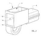
- FIG 3 shows the sensor housing 1 as viewed from the end in which the vent hole 10 is formed.
- the vent hole 10 opens in a generally central region of a substantially planar external surface 12 of the housing 1.
- the housing is configured such that the planar external surface 12 is substantially rectangular and is recessed slightly from the extreme end of the housing so as to define a peripheral lip 13 around the surface 12.
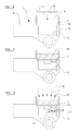
- Figure 4 shows the circuit board 2 being inserted downwardly into the cavity 3 through the opening at the top of the cavity.
- the circuit board 2 carries a number of electronic components 14 which may include, for example, an accelerometer in a generally conventional manner.
- the circuit board 2 is inserted into the cavity 3 of the housing with its components 14 facing downwardly towards the bottom surface 5 of the cavity 3. This is currently favoured for the production of impact sensors, although it should be appreciated that in variants of the invention the circuit board can instead be inserted into the cavity in the reverse orientation such that its components 14 sit on top of the circuit board and hence face away from the bottom surface 5.
- the circuit board 2 is inserted into the cavity as illustrated so that its peripheral edge-regions sit on the inwardly directed mounting shoulder 7. In this position the electronic components 14 mounted on the circuit board are supported in spaced relation to the bottom surface 5 of the cavity 3. When the circuit board 2 is properly inserted in this position, it is then fixed in position by filling the region of the cavity 3 above the circuit board 2 with potting material 15 as illustrated schematically in figure 5 .
- the potting material 15 can take any convenient form known in the art.
- the potting material 15 may be of a type which is cured by the application of heat, or may alternatively be of a sort which hardens due to the mixture of several constituents. In either case, the potting material is injected into the cavity 3 in liquid form and so will flow over the circuit board 2 and around the edge regions of the circuit board sitting on the shoulder 7.
- vent hole 10 permits gases created in the lower part of the cavity 3, below the circuit board 2, to vent through the end wall 11 of the housing (as illustrated schematically by arrows 17 in figure 6 ) in preference to escaping through the potting material 15 which could result in the creation of air bubbles in the potting material which could become trapped as it cures.
- vent hole 10 when the potting material 15 is fully cured the vent hole 10 is no longer required to perform its function of venting gases from the cavity 3. For applications of the sensor where it is important to prevent moisture from entering the sensor unit, the vent hole 10 must therefore then be sealed. For example, where the sensor unit may be required to operate in a humid environment where there is much water vapour in the air, sealing the vent hole 10 is important to prevent the moisture from penetrating the sensor housing and damaging the sensitive components inside.
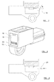
- Figure 7 shows the step of sealing the vent hole 10 after the potting material 15 has substantially fully cured.
- a label 18 is illustrated being applied to the planar external surface 12 of the housing, so as to extend over the vent hole 10, thereby sealing the hole and preventing the ingress of moisture into the housing.
- the label is preferably substantially impermeable to air and may be affixed to the surface 12 via adhesive, and indeed in some embodiments it is envisaged that the adhesive itself may be used to fill the vent hole 12 before the application of the label 18.
- the label will be self-adhesive and hence conveniently affixed to the surface 12 of the housing over the vent hole in a simple and inexpensive manner. In either case, it is envisaged that the label will be affixed in a manner which is effective to substantially hermetically seal the vent hole 10, thereby preventing the passage of moisture, even in vapour form, through the hole.
- Figure 8 shows the label 18 in position over the vent hole 10.
- the label is substantially rectangular in form and is hence configured to substantially fully cover the planar surface 12 of the housing, neatly fitting inside the peripheral lip 13.
- the label 18 may take the form of a product label carrying surface indicia (such as text 19 and/or a barcode 20) representative of the product identity and/or its operational characteristics or the like.
- Figure 9 illustrates an optional additional step in the assembly of the sensor unit, and shows the insertion of a plug 21 into the vent hole 10 from outside the housing after the potting material 15 has been cured but prior to the application of the label 18.
- the plug may be externally screw-threaded and thus is threadedly engaged inside the vent hole 15, either via engagement with a correspondingly formed internal screw thread in the vent hole, or in a self-tapping manner.
- the plug 21 may be press-fitted into the hole as an interference fit.
- the plug 21 will serve to substantially seal the vent hole, and subsequent application of the label 18 over the plug in a similar manner to that described above will serve to further seal the hole and also to retain the plug securely in position.
- the plug 21 may be overmoulded, either partially or entirely, after insertion onto the vent hole 10 in order to retain the plug 21 in position.
Landscapes
- Engineering & Computer Science (AREA)
- Microelectronics & Electronic Packaging (AREA)
- Casings For Electric Apparatus (AREA)
Abstract
Description
- The present invention relates to a method of producing an electronic unit, and more particularly relates to a method of producing an electronic sensor unit for a motor vehicle safety device. Another aspect of the invention relates to an associated sensor unit.
- Modern motor vehicle safety systems typically comprise a number of sensor units which are configured to sense and detect the occurrence or likely occurrence of accidents such as crashes or other impacts involving the motor vehicle. A typical sensor unit of this type comprises one or more sensors responsive to acceleration. The sensors are mounted to a printed circuit board which is mounted inside a housing, the housing typically being moulded of plastics material.
- As will be appreciated, printed circuit boards (and indeed the various components mounted to such boards in an impact sensor) are very delicate and are hence susceptible to damage if they are not adequately protected inside the housing. In order to ensure that the circuit board is securely mounted within the housing of the sensor unit, it is therefore common practice to fill a space within the housing adjacent the circuit board with potting material. The potting material is typically a heat-curable plastics material which is injected into the space adjacent the circuit board in liquid form and which is then cured via the application of heat. Alternatively, the potting material may comprise an epoxy resin mixed with a curing agent. The use of either type of potting material results in the generation of heat as it is cured, and the heat can produce gases. These gases must be allowed to vent from the housing before the potting material becomes significantly cured; otherwise they can cause bubbles in the potting material thereby comprising the effectiveness of the potting material in sealing the circuit board within the housing. It has therefore been proposed previously to provide the housing with a vent hole to permit the gases to vent from the housing as the potting material is cured.
- It is desirable to provide the vent hole in a position which will not be exposed to water or substantial moisture during use of the sensor unit, because of course in such a situation the water or moisture could otherwise penetrate the housing via the vent hole. It has therefore been proposed previously to provide the vent hole within a female connector part of the housing which is configured to receive a male connector for electrical connection to the circuit board. In arrangements of this type, the vent hole becomes covered when the male connector is fully inserted into the female connector part of the sensor housing.
- Nevertheless, arrangements of the type described above are often ineffective at preventing the ingress of moisture, for example through exposure of the sensor to humid environments during the course of its lifetime. It is therefore desirable in some applications to further seal the vent hole itself in order to prevent the ingress of moisture in this manner. One way to achieve this is to fill the vent hole with sealant after the potting material has been cured, for example along a sealing conduit moulded into the sensor housing. However, this sort of proposal, and other similar proposals are inconvenient from a manufacturing point of view and can add cost to the production process.
- It is therefore an object of the present invention to address these shortcomings of the prior art.
- Accordingly, a first aspect of the present invention provides a method of producing an electronic unit comprising a circuit board mounted within a housing, the method comprising the steps of: providing a housing having a vent hole; inserting a circuit board into the housing; filling a space around or against the circuit board with a potting material; curing the potting material; permitting gas within the housing to vent from the housing through the vent hole during at least one of said filling and curing steps; and subsequently sealing said vent hole, the method being characterised in that sealing the vent hole is achieved via the application of a label to the outside of the housing, the label being applied so as to extend across the vent hole and thereby seal the hole from the ingress of moisture into the housing.
- According to a second aspect of the present invention, there is provided a method of producing an electronic sensor unit for a motor vehicle safety device, the sensor unit comprising a circuit board mounted within a housing, and being produced by a method according to the first aspect of the invention.
- According to a third aspect of the present invention, there is provided an electronic sensor unit for a motor vehicle safety device, the unit comprising a circuit board mounted within a housing having a space filled with potting material around or against the circuit board, the unit being characterised in that the housing has a vent hole which is sealed from the ingress of moisture by a label applied to the outside of the housing and which extends across the hole.
- Preferably, the sensor unit is provided in the form of an impact sensor comprising an accelerometer mounted to the circuit board.
- Advantageously, said label is used to seal said vent aperture substantially hermetically.
- Conveniently, said label is a product label bearing indicia representative of the product identity and/or its operational characteristics.
- Preferably, said label is adhesively secured to an outside surface of the housing.
- Advantageously the label is self-adhesive.
- Conveniently, the method of either the first or second aspects of the invention further comprises the step of filling the vent hole with adhesive before the application of said label.
- Preferably, the vent hole is located in a substantially planar external surface of the housing, and wherein said label is affixed to said planar surface.
- Advantageously, said substantially planar external surface and said label are both shaped and configured such that said label substantially covers said planar surface when affixed thereto.
- Conveniently the method of either the first or second aspects of the invention further comprises the step of plugging said vent hole with a plug inserted from outside the housing prior to the application of said label.
- Preferably, said label is applied over said plug so as to retain the plug in position within said vent hole.
- Advantageously, said plug takes the form of a screw-threaded element and wherein said step of plugging the vent hole comprises threadedly engaging said element within said vent hole.
- So that the invention may be more readily understood, and so that further features thereof may be appreciated, embodiments of the invention will now be described by way of example with reference to the accompanying drawings in which:
-
Figure 1 is a perspective view, from above and one end, of a sensor housing and a printed circuit board generally in accordance with an embodiment of the present invention; -
Figure 2 is another perspective view, from a slightly different angle, showing further internal detail of the sensor housing; -
Figure 3 is a perspective view of the housing from above and the opposite end; -
Figure 4 is a schematic cross-sectional view through the housing showing an initial step in the production of the sensor unit; -
Figure 5 is a view corresponding generally to that offigure 4 , but which shows a subsequent step in the production process; -
Figure 6 shows a further step in the production process; -
Figure 7 shows a another subsequent step in the production process; -
Figure 8 is a view generally corresponding to that offigure 3 , but which shows the sensor after the production step offigure 7 ; and -
Figure 9 is a schematic cross-sectional view showing an additional optional step in the production method of the present invention. - Turning firstly to consider
figure 1 , there are illustrated asensor housing 1 and a printedcircuit board 2 prior to assembly to form a completed electronic sensor unit, such as an impact sensor for a motor vehicle safety arrangement. Thehousing 1 is preferably moulded from plastics material and defines an upwardlyopen cavity 3 configured to receive the printedcircuit board 2. One end of the housing carries afemale connector part 4 which is configured to slidingly receive a correspondingly formed male connector (not shown) in order to electrically connect the sensor unit to the circuitry of a safety arrangement in a manner known per se. -
Figure 2 shows thehousing 1 viewed from a different angle, and in particular shows the inner configuration of thecavity 3 in more detail. As will be noted, thecavity 3 is generally rectangular in form, and is shown open infigure 2 , ready for the receipt of thecircuit board 2. Thecavity 3 has abottom surface 5 which is spaced below theupper edge 6 of the housing. A mountingshoulder 7 is formed around the outer periphery of thebottom surface 5 at a position spaced between thebottom surface 5 and theupper edge 6 of the housing. The shoulder is formed in the manner of a step projecting inwardly of thecavity 3 from the peripheral upstanding sidewalls defined around the cavity. - In each corner of the
cavity 3 there is provided a respective mounting post 8 (only one of which is visible infigure 2 ) extending vertically upwardly from theshoulder 7. Eachmounting post 8 may be provided with an internally screw-threaded bore to threadedly receive a respective fixing screw (not shown) used to secure a cover plate (not shown) over thecavity 3 in a manner known per se when the sensor is otherwise fully assembled. As will be noted fromfigure 1 , thecircuit board 2 is generally rectangular in form, having a shape corresponding generally to that of thecavity 3, for receipt therein. However, the corners of the circuit board are each provided with arcuate cut-outs 9, each cut-out 9 being configured to fit around arespective mounting post 8. - Importantly, the
housing 1 is provided with avent hole 10 which extends through the housing at a position between thebottom surface 5 of thecavity 3 and the mountingshoulder 7 and which serves to permit the flow of gas from thecavity 3 to the atmosphere. As illustrated infigure 2 , thevent hole 10 is provided through theend wall 11 of the housing which is opposed to thefemale connector part 4 and moulded as an integral part of the housing. In the event that the wall of the housing in which thevent hole 10 is formed has significant thickness, the vent hole will take the form of an elongate bore therethrough. As will be appreciated, because thehousing 1 is moulded in a single piece, a removable tool is required in order to mould thevent hole 10 through theend wall 11. It is proposed that the toll will be provided in the form of a slide insert which is positioned to define thevent hole 10 as the housing is moulded, and which is slideably retracted from thevent hole 10 before thehousing 1 is removed from the mould. -
Figure 3 shows thesensor housing 1 as viewed from the end in which thevent hole 10 is formed. As will be noted, in the embodiment illustrated thevent hole 10 opens in a generally central region of a substantially planarexternal surface 12 of thehousing 1. In the particular arrangement illustrated infigure 3 , it will furthermore be noted that the housing is configured such that the planarexternal surface 12 is substantially rectangular and is recessed slightly from the extreme end of the housing so as to define aperipheral lip 13 around thesurface 12. - Assembly of a sensor unit in accordance with the invention will now be described with reference to
figures 4 to 9 of the accompanying drawings. -
Figure 4 shows thecircuit board 2 being inserted downwardly into thecavity 3 through the opening at the top of the cavity. As will be noted, thecircuit board 2 carries a number ofelectronic components 14 which may include, for example, an accelerometer in a generally conventional manner. In the arrangement illustrated, thecircuit board 2 is inserted into thecavity 3 of the housing with itscomponents 14 facing downwardly towards thebottom surface 5 of thecavity 3. This is currently favoured for the production of impact sensors, although it should be appreciated that in variants of the invention the circuit board can instead be inserted into the cavity in the reverse orientation such that itscomponents 14 sit on top of the circuit board and hence face away from thebottom surface 5. - The
circuit board 2 is inserted into the cavity as illustrated so that its peripheral edge-regions sit on the inwardly directed mountingshoulder 7. In this position theelectronic components 14 mounted on the circuit board are supported in spaced relation to thebottom surface 5 of thecavity 3. When thecircuit board 2 is properly inserted in this position, it is then fixed in position by filling the region of thecavity 3 above thecircuit board 2 withpotting material 15 as illustrated schematically infigure 5 . The pottingmaterial 15 can take any convenient form known in the art. For example, the pottingmaterial 15 may be of a type which is cured by the application of heat, or may alternatively be of a sort which hardens due to the mixture of several constituents. In either case, the potting material is injected into thecavity 3 in liquid form and so will flow over thecircuit board 2 and around the edge regions of the circuit board sitting on theshoulder 7. - When
sufficient potting material 15 has been injected into thecavity 3 above the circuit board, it is cured so as to harden and securely fix and seal thecircuit board 2 in position within thehousing 1. Regardless of whether the pottingmaterial 15 requires the addition of external heat energy to cure (as illustrated schematically byarrows 16 infigure 6 ), or hardens due to mixture together of different constituents, heat will be generated in the potting material. This generation of heat creates gases within thecavity 3. Gases formed in the upper part of thecavity 3, above thecircuit board 2, can of course naturally escape through the top opening of thecavity 3 through which thecircuit board 2 was inserted. - The
vent hole 10 permits gases created in the lower part of thecavity 3, below thecircuit board 2, to vent through theend wall 11 of the housing (as illustrated schematically byarrows 17 infigure 6 ) in preference to escaping through the pottingmaterial 15 which could result in the creation of air bubbles in the potting material which could become trapped as it cures. - As will be appreciated, when the potting
material 15 is fully cured thevent hole 10 is no longer required to perform its function of venting gases from thecavity 3. For applications of the sensor where it is important to prevent moisture from entering the sensor unit, thevent hole 10 must therefore then be sealed. For example, where the sensor unit may be required to operate in a humid environment where there is much water vapour in the air, sealing thevent hole 10 is important to prevent the moisture from penetrating the sensor housing and damaging the sensitive components inside. -
Figure 7 shows the step of sealing thevent hole 10 after thepotting material 15 has substantially fully cured. Alabel 18 is illustrated being applied to the planarexternal surface 12 of the housing, so as to extend over thevent hole 10, thereby sealing the hole and preventing the ingress of moisture into the housing. The label is preferably substantially impermeable to air and may be affixed to thesurface 12 via adhesive, and indeed in some embodiments it is envisaged that the adhesive itself may be used to fill thevent hole 12 before the application of thelabel 18. However, in other embodiments it is envisaged that the label will be self-adhesive and hence conveniently affixed to thesurface 12 of the housing over the vent hole in a simple and inexpensive manner. In either case, it is envisaged that the label will be affixed in a manner which is effective to substantially hermetically seal thevent hole 10, thereby preventing the passage of moisture, even in vapour form, through the hole. -
Figure 8 shows thelabel 18 in position over thevent hole 10. As will be noted, the label is substantially rectangular in form and is hence configured to substantially fully cover theplanar surface 12 of the housing, neatly fitting inside theperipheral lip 13. Thelabel 18 may take the form of a product label carrying surface indicia (such astext 19 and/or a barcode 20) representative of the product identity and/or its operational characteristics or the like. -
Figure 9 illustrates an optional additional step in the assembly of the sensor unit, and shows the insertion of aplug 21 into thevent hole 10 from outside the housing after thepotting material 15 has been cured but prior to the application of thelabel 18. It is envisaged that the plug may be externally screw-threaded and thus is threadedly engaged inside thevent hole 15, either via engagement with a correspondingly formed internal screw thread in the vent hole, or in a self-tapping manner. Alternatively, however, theplug 21 may be press-fitted into the hole as an interference fit. As will be appreciated, theplug 21 will serve to substantially seal the vent hole, and subsequent application of thelabel 18 over the plug in a similar manner to that described above will serve to further seal the hole and also to retain the plug securely in position. Alternatively, it is envisaged that theplug 21 may be overmoulded, either partially or entirely, after insertion onto thevent hole 10 in order to retain theplug 21 in position. - When used in this specification and claims, the terms "comprises" and "comprising" and variations thereof mean that the specified features, steps or integers are included. The terms are not to be interpreted to exclude the presence of other features, steps or integers.
- The features disclosed in the foregoing description, or in the following claims, or in the accompanying drawings, expressed in their specific forms or in terms of a means for performing the disclosed function, or a method or process for obtaining the disclosed results, as appropriate, may, separately, or in any combination of such features, be utilised for realising the invention in diverse forms thereof.
- While the invention has been described in conjunction with the exemplary embodiments described above, many equivalent modifications and variations will be apparent to those skilled in the art when given this disclosure. Accordingly, the exemplary embodiments of the invention set forth above are considered to be illustrative and not limiting. Various changes to the described embodiments may be made without departing from the spirit and scope of the invention.
Claims (15)
- A method of producing an electronic unit comprising a circuit board (2) mounted within a housing (1), the method comprising the steps of: providing a housing (1) having a vent hole (10); inserting a circuit board (2) into the housing; filling a space (3) around or against the circuit board with a potting material (15); curing the potting material; permitting gas within the housing to vent from the housing through the vent hole during at least one of said filling and curing steps; and subsequently sealing said vent hole, the method being characterised in that sealing the vent hole is achieved via the application of a label (18) to the outside of the housing, the label being applied so as to extend across the vent hole and thereby seal the hole from the ingress of moisture into the housing.
- A method according to claim 1, wherein said label (18) is used to seal said vent hole (10) substantially hermetically.
- A method according to claim 1 or claim 2, wherein said label (18) is a product label bearing indicia (19, 20) representative of the product identity and/or its operational characteristics.
- A method according to any preceding claim, wherein said label (18) is adhesively secured to an outside surface (12) of the housing (1).
- A method according to any preceding claim, wherein the label (18) is self-adhesive.
- A method according to claim 5, further comprising the step of filling the vent hole (10) with adhesive before the application of said label.
- A method according to any preceding claim, wherein the vent hole (10) is located in a substantially planar external surface (12) of the housing, and wherein said label is affixed to said planar surface.
- A method according to claim 7, wherein said substantially planar external surface (12) and said label (18) are both shaped and configured such that said label substantially covers said planar surface when affixed thereto.
- A method according to any preceding step, further comprising the step of plugging said vent hole (10) with a plug (21) inserted from outside the housing prior to the application of said label (18).
- A method according to claim 9, wherein said label (18) is applied over said plug (21) so as to retain the plug in position within said vent hole.
- A method according to claim 9 or claim 10, wherein said plug (21) takes the form of a screw-threaded element and wherein said step of plugging the vent hole (10) comprises threadedly engaging said element within said vent hole.
- A method of producing an electronic sensor unit for a motor vehicle safety device, the sensor unit comprising a circuit board (2) mounted within a housing (1), and being produced by a method according to any preceding claim.
- A method according to claim 12, wherein the sensor unit is an impact sensor unit comprising an accelerometer (14) mounted to the circuit board (20.
- An electronic sensor unit for a motor vehicle safety device, the unit comprising a circuit board (2) mounted within a housing (1) having a space (3) filled with potting material (15) around or against the circuit board, wherein the housing has a vent hole (100 which is sealed from the ingress of moisture by a label (18) applied to the outside of the housing and which extends across the hole.
- An electronic sensor unit according to claim 14 provided in the form of an impact sensor comprising an accelerometer (14) mounted to the circuit board (2).
Priority Applications (1)
| Application Number | Priority Date | Filing Date | Title |
|---|---|---|---|
| EP11152127.4A EP2480059B1 (en) | 2011-01-25 | 2011-01-25 | Improvements in or relating to the production of an electronic unit, such as a sensor unit for a motor vehicle safety device |
Applications Claiming Priority (1)
| Application Number | Priority Date | Filing Date | Title |
|---|---|---|---|
| EP11152127.4A EP2480059B1 (en) | 2011-01-25 | 2011-01-25 | Improvements in or relating to the production of an electronic unit, such as a sensor unit for a motor vehicle safety device |
Publications (2)
| Publication Number | Publication Date |
|---|---|
| EP2480059A1 true EP2480059A1 (en) | 2012-07-25 |
| EP2480059B1 EP2480059B1 (en) | 2013-11-20 |
Family
ID=44310346
Family Applications (1)
| Application Number | Title | Priority Date | Filing Date |
|---|---|---|---|
| EP11152127.4A Active EP2480059B1 (en) | 2011-01-25 | 2011-01-25 | Improvements in or relating to the production of an electronic unit, such as a sensor unit for a motor vehicle safety device |
Country Status (1)
| Country | Link |
|---|---|
| EP (1) | EP2480059B1 (en) |
Cited By (3)
| Publication number | Priority date | Publication date | Assignee | Title |
|---|---|---|---|---|
| US9497868B2 (en) | 2014-04-17 | 2016-11-15 | Continental Automotive Systems, Inc. | Electronics enclosure |
| CN113711447A (en) * | 2019-04-11 | 2021-11-26 | 维宁尔美国公司 | Electronic unit having vent holes integrated with terminal holes |
| WO2026032909A1 (en) * | 2024-08-06 | 2026-02-12 | Tdk Electronics Ag | System assembly, pressure sensor assembly and method for producing a system assembly |
Citations (3)
| Publication number | Priority date | Publication date | Assignee | Title |
|---|---|---|---|---|
| EP0862354A2 (en) * | 1997-02-28 | 1998-09-02 | TEMIC TELEFUNKEN microelectronic GmbH | Closing device for pressure equalising apertures |
| US7048564B1 (en) * | 2005-05-27 | 2006-05-23 | Delphi Technologies, Inc. | Sealed electronic module with fastenerless circuit board support post |
| US20100079934A1 (en) * | 2008-09-26 | 2010-04-01 | Denso Corporation | Electronic circuit device |
-
2011
- 2011-01-25 EP EP11152127.4A patent/EP2480059B1/en active Active
Patent Citations (3)
| Publication number | Priority date | Publication date | Assignee | Title |
|---|---|---|---|---|
| EP0862354A2 (en) * | 1997-02-28 | 1998-09-02 | TEMIC TELEFUNKEN microelectronic GmbH | Closing device for pressure equalising apertures |
| US7048564B1 (en) * | 2005-05-27 | 2006-05-23 | Delphi Technologies, Inc. | Sealed electronic module with fastenerless circuit board support post |
| US20100079934A1 (en) * | 2008-09-26 | 2010-04-01 | Denso Corporation | Electronic circuit device |
Cited By (4)
| Publication number | Priority date | Publication date | Assignee | Title |
|---|---|---|---|---|
| US9497868B2 (en) | 2014-04-17 | 2016-11-15 | Continental Automotive Systems, Inc. | Electronics enclosure |
| CN113711447A (en) * | 2019-04-11 | 2021-11-26 | 维宁尔美国公司 | Electronic unit having vent holes integrated with terminal holes |
| EP3953995A4 (en) * | 2019-04-11 | 2023-01-11 | Veoneer US, LLC | ELECTRONIC UNIT WITH VENTILATION INTEGRATED IN THE PORT |
| WO2026032909A1 (en) * | 2024-08-06 | 2026-02-12 | Tdk Electronics Ag | System assembly, pressure sensor assembly and method for producing a system assembly |
Also Published As
| Publication number | Publication date |
|---|---|
| EP2480059B1 (en) | 2013-11-20 |
Similar Documents
| Publication | Publication Date | Title |
|---|---|---|
| US7118646B2 (en) | Method of manufacturing a sealed electronic module | |
| US20190380220A1 (en) | Waterproof electronic device and production method of waterproof electronic device | |
| US9190766B2 (en) | Electronic control apparatus for vehicle using water proof type housing sealing and method thereof | |
| EP2480059B1 (en) | Improvements in or relating to the production of an electronic unit, such as a sensor unit for a motor vehicle safety device | |
| US8973437B2 (en) | Condensate sensing device | |
| US10856419B2 (en) | Printed circuit board assembly | |
| CN107926120A (en) | With can be via the electronic apparatus module and its manufacture method of the device that socket element is flexibly placed | |
| JP6193085B2 (en) | Manufacturing method of electrical equipment and electrical equipment | |
| US8578770B2 (en) | Encapsulated liquid level sensor device | |
| KR20160026895A (en) | Sensor with a sealing coating | |
| EP2934076B1 (en) | Electronics enclosure | |
| CN104316094B (en) | Glue seals formula sensor and its manufacturing process | |
| US20080030973A1 (en) | Method for the production of a sensor and sensor | |
| US20110255224A1 (en) | Electric component and pin header for such a component | |
| KR100788128B1 (en) | Speed sensor for automobile and assembly method | |
| JP5028441B2 (en) | Electronic control device | |
| EP2819826B1 (en) | Method and apparatus for sky-line potting | |
| JP4937976B2 (en) | Manufacturing method of connector device | |
| CN111799229B (en) | Electronic device and method for manufacturing electronic device | |
| JPH11103178A (en) | Substrate holding structure in electronic control unit for vehicle mounting | |
| JP5724974B2 (en) | Lead-acid battery, lead-acid battery terminal sealing part cover member, lead-acid battery terminal sealing method | |
| JP5548663B2 (en) | Manufacturing method of electronic control unit | |
| KR101735737B1 (en) | Electronic control unit for vehicle | |
| US7807934B2 (en) | Printed circuit board having protection means and a method of use thereof | |
| JP2007311706A (en) | Circuit board sealing method and circuit board device |
Legal Events
| Date | Code | Title | Description |
|---|---|---|---|
| PUAI | Public reference made under article 153(3) epc to a published international application that has entered the european phase |
Free format text: ORIGINAL CODE: 0009012 |
|
| 17P | Request for examination filed |
Effective date: 20120321 |
|
| AK | Designated contracting states |
Kind code of ref document: A1 Designated state(s): AL AT BE BG CH CY CZ DE DK EE ES FI FR GB GR HR HU IE IS IT LI LT LU LV MC MK MT NL NO PL PT RO RS SE SI SK SM TR |
|
| AX | Request for extension of the european patent |
Extension state: BA ME |
|
| GRAP | Despatch of communication of intention to grant a patent |
Free format text: ORIGINAL CODE: EPIDOSNIGR1 |
|
| INTG | Intention to grant announced |
Effective date: 20130611 |
|
| GRAS | Grant fee paid |
Free format text: ORIGINAL CODE: EPIDOSNIGR3 |
|
| GRAA | (expected) grant |
Free format text: ORIGINAL CODE: 0009210 |
|
| AK | Designated contracting states |
Kind code of ref document: B1 Designated state(s): AL AT BE BG CH CY CZ DE DK EE ES FI FR GB GR HR HU IE IS IT LI LT LU LV MC MK MT NL NO PL PT RO RS SE SI SK SM TR |
|
| REG | Reference to a national code |
Ref country code: GB Ref legal event code: FG4D |
|
| REG | Reference to a national code |
Ref country code: CH Ref legal event code: EP |
|
| REG | Reference to a national code |
Ref country code: AT Ref legal event code: REF Ref document number: 642294 Country of ref document: AT Kind code of ref document: T Effective date: 20131215 |
|
| REG | Reference to a national code |
Ref country code: IE Ref legal event code: FG4D |
|
| REG | Reference to a national code |
Ref country code: DE Ref legal event code: R096 Ref document number: 602011003794 Country of ref document: DE Effective date: 20140123 |
|
| PGFP | Annual fee paid to national office [announced via postgrant information from national office to epo] |
Ref country code: FR Payment date: 20131209 Year of fee payment: 4 |
|
| REG | Reference to a national code |
Ref country code: NL Ref legal event code: VDEP Effective date: 20131120 |
|
| REG | Reference to a national code |
Ref country code: AT Ref legal event code: MK05 Ref document number: 642294 Country of ref document: AT Kind code of ref document: T Effective date: 20131120 |
|
| REG | Reference to a national code |
Ref country code: LT Ref legal event code: MG4D |
|
| PG25 | Lapsed in a contracting state [announced via postgrant information from national office to epo] |
Ref country code: LT Free format text: LAPSE BECAUSE OF FAILURE TO SUBMIT A TRANSLATION OF THE DESCRIPTION OR TO PAY THE FEE WITHIN THE PRESCRIBED TIME-LIMIT Effective date: 20131120 Ref country code: IS Free format text: LAPSE BECAUSE OF FAILURE TO SUBMIT A TRANSLATION OF THE DESCRIPTION OR TO PAY THE FEE WITHIN THE PRESCRIBED TIME-LIMIT Effective date: 20140320 Ref country code: NO Free format text: LAPSE BECAUSE OF FAILURE TO SUBMIT A TRANSLATION OF THE DESCRIPTION OR TO PAY THE FEE WITHIN THE PRESCRIBED TIME-LIMIT Effective date: 20140220 Ref country code: SE Free format text: LAPSE BECAUSE OF FAILURE TO SUBMIT A TRANSLATION OF THE DESCRIPTION OR TO PAY THE FEE WITHIN THE PRESCRIBED TIME-LIMIT Effective date: 20131120 Ref country code: HR Free format text: LAPSE BECAUSE OF FAILURE TO SUBMIT A TRANSLATION OF THE DESCRIPTION OR TO PAY THE FEE WITHIN THE PRESCRIBED TIME-LIMIT Effective date: 20131120 Ref country code: NL Free format text: LAPSE BECAUSE OF FAILURE TO SUBMIT A TRANSLATION OF THE DESCRIPTION OR TO PAY THE FEE WITHIN THE PRESCRIBED TIME-LIMIT Effective date: 20131120 Ref country code: FI Free format text: LAPSE BECAUSE OF FAILURE TO SUBMIT A TRANSLATION OF THE DESCRIPTION OR TO PAY THE FEE WITHIN THE PRESCRIBED TIME-LIMIT Effective date: 20131120 |
|
| PG25 | Lapsed in a contracting state [announced via postgrant information from national office to epo] |
Ref country code: ES Free format text: LAPSE BECAUSE OF FAILURE TO SUBMIT A TRANSLATION OF THE DESCRIPTION OR TO PAY THE FEE WITHIN THE PRESCRIBED TIME-LIMIT Effective date: 20131120 Ref country code: BE Free format text: LAPSE BECAUSE OF FAILURE TO SUBMIT A TRANSLATION OF THE DESCRIPTION OR TO PAY THE FEE WITHIN THE PRESCRIBED TIME-LIMIT Effective date: 20131120 Ref country code: LV Free format text: LAPSE BECAUSE OF FAILURE TO SUBMIT A TRANSLATION OF THE DESCRIPTION OR TO PAY THE FEE WITHIN THE PRESCRIBED TIME-LIMIT Effective date: 20131120 Ref country code: AT Free format text: LAPSE BECAUSE OF FAILURE TO SUBMIT A TRANSLATION OF THE DESCRIPTION OR TO PAY THE FEE WITHIN THE PRESCRIBED TIME-LIMIT Effective date: 20131120 Ref country code: RS Free format text: LAPSE BECAUSE OF FAILURE TO SUBMIT A TRANSLATION OF THE DESCRIPTION OR TO PAY THE FEE WITHIN THE PRESCRIBED TIME-LIMIT Effective date: 20131120 |
|
| PG25 | Lapsed in a contracting state [announced via postgrant information from national office to epo] |
Ref country code: PT Free format text: LAPSE BECAUSE OF FAILURE TO SUBMIT A TRANSLATION OF THE DESCRIPTION OR TO PAY THE FEE WITHIN THE PRESCRIBED TIME-LIMIT Effective date: 20140320 |
|
| PG25 | Lapsed in a contracting state [announced via postgrant information from national office to epo] |
Ref country code: EE Free format text: LAPSE BECAUSE OF FAILURE TO SUBMIT A TRANSLATION OF THE DESCRIPTION OR TO PAY THE FEE WITHIN THE PRESCRIBED TIME-LIMIT Effective date: 20131120 |
|
| REG | Reference to a national code |
Ref country code: DE Ref legal event code: R097 Ref document number: 602011003794 Country of ref document: DE |
|
| PG25 | Lapsed in a contracting state [announced via postgrant information from national office to epo] |
Ref country code: PL Free format text: LAPSE BECAUSE OF FAILURE TO SUBMIT A TRANSLATION OF THE DESCRIPTION OR TO PAY THE FEE WITHIN THE PRESCRIBED TIME-LIMIT Effective date: 20131120 Ref country code: CZ Free format text: LAPSE BECAUSE OF FAILURE TO SUBMIT A TRANSLATION OF THE DESCRIPTION OR TO PAY THE FEE WITHIN THE PRESCRIBED TIME-LIMIT Effective date: 20131120 Ref country code: RO Free format text: LAPSE BECAUSE OF FAILURE TO SUBMIT A TRANSLATION OF THE DESCRIPTION OR TO PAY THE FEE WITHIN THE PRESCRIBED TIME-LIMIT Effective date: 20131120 Ref country code: SK Free format text: LAPSE BECAUSE OF FAILURE TO SUBMIT A TRANSLATION OF THE DESCRIPTION OR TO PAY THE FEE WITHIN THE PRESCRIBED TIME-LIMIT Effective date: 20131120 Ref country code: LU Free format text: LAPSE BECAUSE OF FAILURE TO SUBMIT A TRANSLATION OF THE DESCRIPTION OR TO PAY THE FEE WITHIN THE PRESCRIBED TIME-LIMIT Effective date: 20140125 |
|
| REG | Reference to a national code |
Ref country code: CH Ref legal event code: PL |
|
| PLBE | No opposition filed within time limit |
Free format text: ORIGINAL CODE: 0009261 |
|
| STAA | Information on the status of an ep patent application or granted ep patent |
Free format text: STATUS: NO OPPOSITION FILED WITHIN TIME LIMIT |
|
| PG25 | Lapsed in a contracting state [announced via postgrant information from national office to epo] |
Ref country code: DK Free format text: LAPSE BECAUSE OF FAILURE TO SUBMIT A TRANSLATION OF THE DESCRIPTION OR TO PAY THE FEE WITHIN THE PRESCRIBED TIME-LIMIT Effective date: 20131120 |
|
| 26N | No opposition filed |
Effective date: 20140821 |
|
| PG25 | Lapsed in a contracting state [announced via postgrant information from national office to epo] |
Ref country code: CH Free format text: LAPSE BECAUSE OF NON-PAYMENT OF DUE FEES Effective date: 20140131 Ref country code: LI Free format text: LAPSE BECAUSE OF NON-PAYMENT OF DUE FEES Effective date: 20140131 |
|
| REG | Reference to a national code |
Ref country code: IE Ref legal event code: MM4A |
|
| REG | Reference to a national code |
Ref country code: DE Ref legal event code: R097 Ref document number: 602011003794 Country of ref document: DE Effective date: 20140821 |
|
| PG25 | Lapsed in a contracting state [announced via postgrant information from national office to epo] |
Ref country code: IE Free format text: LAPSE BECAUSE OF NON-PAYMENT OF DUE FEES Effective date: 20140125 |
|
| PG25 | Lapsed in a contracting state [announced via postgrant information from national office to epo] |
Ref country code: SI Free format text: LAPSE BECAUSE OF FAILURE TO SUBMIT A TRANSLATION OF THE DESCRIPTION OR TO PAY THE FEE WITHIN THE PRESCRIBED TIME-LIMIT Effective date: 20131120 |
|
| PG25 | Lapsed in a contracting state [announced via postgrant information from national office to epo] |
Ref country code: MC Free format text: LAPSE BECAUSE OF FAILURE TO SUBMIT A TRANSLATION OF THE DESCRIPTION OR TO PAY THE FEE WITHIN THE PRESCRIBED TIME-LIMIT Effective date: 20131120 |
|
| GBPC | Gb: european patent ceased through non-payment of renewal fee |
Effective date: 20150125 |
|
| PG25 | Lapsed in a contracting state [announced via postgrant information from national office to epo] |
Ref country code: GB Free format text: LAPSE BECAUSE OF NON-PAYMENT OF DUE FEES Effective date: 20150125 |
|
| REG | Reference to a national code |
Ref country code: FR Ref legal event code: ST Effective date: 20150930 |
|
| PG25 | Lapsed in a contracting state [announced via postgrant information from national office to epo] |
Ref country code: FR Free format text: LAPSE BECAUSE OF NON-PAYMENT OF DUE FEES Effective date: 20150202 |
|
| PG25 | Lapsed in a contracting state [announced via postgrant information from national office to epo] |
Ref country code: MT Free format text: LAPSE BECAUSE OF FAILURE TO SUBMIT A TRANSLATION OF THE DESCRIPTION OR TO PAY THE FEE WITHIN THE PRESCRIBED TIME-LIMIT Effective date: 20131120 |
|
| PG25 | Lapsed in a contracting state [announced via postgrant information from national office to epo] |
Ref country code: SM Free format text: LAPSE BECAUSE OF FAILURE TO SUBMIT A TRANSLATION OF THE DESCRIPTION OR TO PAY THE FEE WITHIN THE PRESCRIBED TIME-LIMIT Effective date: 20131120 |
|
| PG25 | Lapsed in a contracting state [announced via postgrant information from national office to epo] |
Ref country code: GR Free format text: LAPSE BECAUSE OF FAILURE TO SUBMIT A TRANSLATION OF THE DESCRIPTION OR TO PAY THE FEE WITHIN THE PRESCRIBED TIME-LIMIT Effective date: 20140221 Ref country code: BG Free format text: LAPSE BECAUSE OF FAILURE TO SUBMIT A TRANSLATION OF THE DESCRIPTION OR TO PAY THE FEE WITHIN THE PRESCRIBED TIME-LIMIT Effective date: 20131120 Ref country code: IT Free format text: LAPSE BECAUSE OF FAILURE TO SUBMIT A TRANSLATION OF THE DESCRIPTION OR TO PAY THE FEE WITHIN THE PRESCRIBED TIME-LIMIT Effective date: 20131120 Ref country code: CY Free format text: LAPSE BECAUSE OF FAILURE TO SUBMIT A TRANSLATION OF THE DESCRIPTION OR TO PAY THE FEE WITHIN THE PRESCRIBED TIME-LIMIT Effective date: 20131120 |
|
| PG25 | Lapsed in a contracting state [announced via postgrant information from national office to epo] |
Ref country code: TR Free format text: LAPSE BECAUSE OF FAILURE TO SUBMIT A TRANSLATION OF THE DESCRIPTION OR TO PAY THE FEE WITHIN THE PRESCRIBED TIME-LIMIT Effective date: 20131120 Ref country code: HU Free format text: LAPSE BECAUSE OF FAILURE TO SUBMIT A TRANSLATION OF THE DESCRIPTION OR TO PAY THE FEE WITHIN THE PRESCRIBED TIME-LIMIT; INVALID AB INITIO Effective date: 20110125 |
|
| PG25 | Lapsed in a contracting state [announced via postgrant information from national office to epo] |
Ref country code: MK Free format text: LAPSE BECAUSE OF FAILURE TO SUBMIT A TRANSLATION OF THE DESCRIPTION OR TO PAY THE FEE WITHIN THE PRESCRIBED TIME-LIMIT Effective date: 20131120 |
|
| PG25 | Lapsed in a contracting state [announced via postgrant information from national office to epo] |
Ref country code: AL Free format text: LAPSE BECAUSE OF FAILURE TO SUBMIT A TRANSLATION OF THE DESCRIPTION OR TO PAY THE FEE WITHIN THE PRESCRIBED TIME-LIMIT Effective date: 20131120 |
|
| REG | Reference to a national code |
Ref country code: DE Ref legal event code: R081 Ref document number: 602011003794 Country of ref document: DE Owner name: VEONEER SWEDEN AB, SE Free format text: FORMER OWNER: AUTOLIV DEVELOPMENT AB, VARGARDA, SE |
|
| REG | Reference to a national code |
Ref country code: DE Ref legal event code: R081 Ref document number: 602011003794 Country of ref document: DE Owner name: VEONEER SWEDEN SAFETY SYSTEMS AB, SE Free format text: FORMER OWNER: VEONEER SWEDEN AB, VARGARDA, SE Ref country code: DE Ref legal event code: R081 Ref document number: 602011003794 Country of ref document: DE Owner name: VEONEER PASSIVE CO. AB, SE Free format text: FORMER OWNER: VEONEER SWEDEN AB, VARGARDA, SE Ref country code: DE Ref legal event code: R082 Ref document number: 602011003794 Country of ref document: DE |
|
| REG | Reference to a national code |
Ref country code: DE Ref legal event code: R081 Ref document number: 602011003794 Country of ref document: DE Owner name: VEONEER SWEDEN SAFETY SYSTEMS AB, SE Free format text: FORMER OWNER: VEONEER PASSIVE CO. AB, STOCKHOLM, SE |
|
| PGFP | Annual fee paid to national office [announced via postgrant information from national office to epo] |
Ref country code: DE Payment date: 20260120 Year of fee payment: 16 |