EP2480043A1 - Method and device for identifying universal serial bus (usb) insertion or charger insertion of mobile terminal - Google Patents
Method and device for identifying universal serial bus (usb) insertion or charger insertion of mobile terminal Download PDFInfo
- Publication number
- EP2480043A1 EP2480043A1 EP10816614A EP10816614A EP2480043A1 EP 2480043 A1 EP2480043 A1 EP 2480043A1 EP 10816614 A EP10816614 A EP 10816614A EP 10816614 A EP10816614 A EP 10816614A EP 2480043 A1 EP2480043 A1 EP 2480043A1
- Authority
- EP
- European Patent Office
- Prior art keywords
- module
- usb
- port
- charger
- switch module
- Prior art date
- Legal status (The legal status is an assumption and is not a legal conclusion. Google has not performed a legal analysis and makes no representation as to the accuracy of the status listed.)
- Granted
Links
Images


Classifications
-
- H—ELECTRICITY
- H02—GENERATION; CONVERSION OR DISTRIBUTION OF ELECTRIC POWER
- H02J—ELECTRIC POWER NETWORKS; CIRCUIT ARRANGEMENTS OR SYSTEMS FOR SUPPLYING OR DISTRIBUTING ELECTRIC POWER; SYSTEMS FOR STORING ELECTRIC ENERGY
- H02J7/00—Circuit arrangements for charging or discharging batteries or for supplying loads from batteries
- H02J7/60—Circuit arrangements for charging or discharging batteries or for supplying loads from batteries including safety or protection arrangements
- H02J7/685—Circuit arrangements for charging or discharging batteries or for supplying loads from batteries including safety or protection arrangements using connection detecting circuits
-
- H—ELECTRICITY
- H02—GENERATION; CONVERSION OR DISTRIBUTION OF ELECTRIC POWER
- H02J—ELECTRIC POWER NETWORKS; CIRCUIT ARRANGEMENTS OR SYSTEMS FOR SUPPLYING OR DISTRIBUTING ELECTRIC POWER; SYSTEMS FOR STORING ELECTRIC ENERGY
- H02J7/00—Circuit arrangements for charging or discharging batteries or for supplying loads from batteries
- H02J7/40—Circuit arrangements for charging or discharging batteries or for supplying loads from batteries characterised by the exchange of charge or discharge related data
- H02J7/47—Arrangements for checking compatibility or authentication between one component, e.g. a battery or a battery charger, and another component, e.g. a power source
-
- H—ELECTRICITY
- H02—GENERATION; CONVERSION OR DISTRIBUTION OF ELECTRIC POWER
- H02J—ELECTRIC POWER NETWORKS; CIRCUIT ARRANGEMENTS OR SYSTEMS FOR SUPPLYING OR DISTRIBUTING ELECTRIC POWER; SYSTEMS FOR STORING ELECTRIC ENERGY
- H02J2105/00—Networks for supplying or distributing electric power characterised by their spatial reach or by the load
- H02J2105/40—Networks for supplying or distributing electric power characterised by their spatial reach or by the load characterised by the loads connecting to the networks or being supplied by the networks
- H02J2105/44—Portable electronic devices
-
- H—ELECTRICITY
- H02—GENERATION; CONVERSION OR DISTRIBUTION OF ELECTRIC POWER
- H02J—ELECTRIC POWER NETWORKS; CIRCUIT ARRANGEMENTS OR SYSTEMS FOR SUPPLYING OR DISTRIBUTING ELECTRIC POWER; SYSTEMS FOR STORING ELECTRIC ENERGY
- H02J2207/00—Details of circuit arrangements for charging or discharging batteries or supplying loads from batteries
- H02J2207/40—Details of circuit arrangements for charging or discharging batteries or supplying loads from batteries adapted for charging from various sources, e.g. AC, DC or multivoltage
-
- H—ELECTRICITY
- H02—GENERATION; CONVERSION OR DISTRIBUTION OF ELECTRIC POWER
- H02J—ELECTRIC POWER NETWORKS; CIRCUIT ARRANGEMENTS OR SYSTEMS FOR SUPPLYING OR DISTRIBUTING ELECTRIC POWER; SYSTEMS FOR STORING ELECTRIC ENERGY
- H02J7/00—Circuit arrangements for charging or discharging batteries or for supplying loads from batteries
-
- H—ELECTRICITY
- H04—ELECTRIC COMMUNICATION TECHNIQUE
- H04M—TELEPHONIC COMMUNICATION
- H04M1/00—Substation equipment, e.g. for use by subscribers
- H04M1/72—Mobile telephones; Cordless telephones, i.e. devices for establishing wireless links to base stations without route selection
- H04M1/724—User interfaces specially adapted for cordless or mobile telephones
- H04M1/72403—User interfaces specially adapted for cordless or mobile telephones with means for local support of applications that increase the functionality
- H04M1/72409—User interfaces specially adapted for cordless or mobile telephones with means for local support of applications that increase the functionality by interfacing with external accessories
Definitions
- the present invention relates to the field of mobile communication terminals, and more specifically, to a circuit to identify plugged USB or charger.
- USB & USB A series USB cables when designing charging cables.
- the application of said common USB cable as a charging and data line for cell phone can maximize cost benefits and social benefits, such as energy saving and environmental protection.
- the cell phone When a user uses said common USB cable to charge with a charger or via USB or to transmit USB data, the cell phone will determine whether it is a charger or a computer that has been plugged in.
- the plug There are numerous methods to determine the plug by various terminal manufacturers and upstream development platforms, some of which make correct determination but are complex, while others use simple methods but tend to reach incorrect determination.
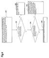
- Fig.1 is a schematic of the interface of a charger according to the new national standard.
- the left interface is a supply of 50Hz 220VAC commercial power
- the right interface is the 5V direct current (DC) output terminal of the charger. It can be seen that D- and D+ interfaces of the charger's output are short circuited.
- data D+ and D- pins of standard USB mini ports and USB in A port plugs are usually shorter than 5V and GND pins.
- the cell phone When a cell phone is connected to a charger, either the cell phone is plugged into a mini port or a charger is plugged into an A port, the cell phone would determine it to be a USB plug-in and enter a USB mode if the user plugs in very slowly or only plugs in half way. Once the cell phone enters the USB mode, it will not come back to the charger mode even when the charging plug is completely plugged in later. The reason is because many terminal manufacturers or development platforms must perform pullout determination before determining the next plug-in action.
- the object of the present invention is to provide a method to identify USB or charger plugged into a mobile terminal and an identification device thereof, which can quickly and accurately identify the type of USB or charger plugged into the terminal.
- the present invention employs the following technical solution:
- a device for identifying USB or charger plugged into a mobile terminal comprising a USB interface module connected with an external power supply device, wherein it further comprises an interface detection and control module, an electronic switch module, a charging switch module, an identification module and a baseband USB data transceiving module;
- Said identification device wherein it further comprises a charging module connected with the USB interface module and charging switch module, respectively, and said charging module is used for selecting corresponding charging method according to the type of said external power supply device identified by said identification module.
- said electronic switch module is an integrated chip with model number of FSUB30L10
- pin 1 (S control port) of said FSUB30L10 integrated chip is connected with said interface detection and control module
- pin 8 (HSD2- port) and pin 5 (GND port) are connected with reference ground
- pin 4 is connected with D+ port of the USB interface module
- pin 6 is connected with D- port of the USB interface module
- pin 3 (HSD2+ port) and pin 7 (HSD2- port) are connected with said baseband USB data transceiving module.
- said charging switch module comprises a field-effect transistor (FET) with model number of SI8415DB
- S pole of said SI8415DB FET is connected with pin 2 (HSD1+ port) of said FSUB30L10 integrated chip via a resistor R598, two D poles of said SI8415DB FET are connected with said identification module and charging module, and G pole of said SI8415DB FET is connected with reference ground via resistor R11 and resistor R590.
- FET field-effect transistor
- a method to identify USB or charger plugged into a mobile terminal comprising the steps:
- the present invention provides a method to identify USB or charger plugged into a mobile terminal and an identification device thereof.
- said identification device makes a terminal to preferentially enter a USB mode, while according to the ultimately detected D-signal state, interrupt responses can be flexibly generated to accurately determine USB or charger. It can quickly and accurately identify the type of USB or charger plugged into the terminal.
- the present invention provides a method to identify USB or charger plugged into a mobile terminal and an identification device thereof. To make the object, technical solution and advantages of the present invention clearer, the present invention is further described in detail below with reference to the accompanying drawings and embodiments.
- a device to identify USB or charger plugged into a mobile terminal comprises a USB interface module 110 plugged into an external power supply device, said external power supply device comprising a standard charger or a USB data line connected with a computer; wherein, the identification device according to the present invention further comprises: an interface detection and control module 120, an electronic switch module 130, a charging switch module 140, an identification module 150 and a baseband USB data transceiving module 160;
- said interface detection and control module 120 is connected with said USB interface module 110 for detecting D-port signal of said USB interface module, and generating interrupt responses according to changes of said D-port signal so as to output a corresponding control signal to the electronic switch module 130; wherein said corresponding control signal comprises a first control signal and a second control signal, when said interface detection and control module 120 detects that an external power supply device is plugged into said USB interface module 110, said interface detection and control module 120 initializes and outputs a first control signal to said electronic switch, such that the terminal preferentially enters a USB mode, and when said interface detection and control module 120 detects changes to D-port of the USB interface module 110, said interface detection and control module 120 generates an interrupt and outputs a second control signal to said electronic switch 130, such that the terminal enters a charger working mode.
- Said electronic switch module 130 is connected with said USB interface module 110 for receiving input signals from said USB interface module 110, and selecting said input signals according to said control signal to connect with said baseband USB data transceiving module 160 or charging switch module 140, such that the terminal enters a USB module or a charger working mode.
- Said charging switch module 140 is connected with said electronic switch module 130 for switching and outputting an identification signal according to an output signal of said electronic switch module 430.
- Said identification module 150 is connected with said USB interface module 110 and charging switch module 140, respectively, for identifying the type of said external power supply device according to signal states of said USB interface module 110 and charging switch module 140.
- the device to identify USB or charger plugged into a mobile terminal provided in Embodiment 1 of the present invention further comprises a charging module 170 connected with the USB interface module 110 and charging switch module 140, respectively, and said charging module 170 is used for selecting corresponding charging method according to the type of said external power supply device identified by said identification module 150, namely, said corresponding charging method comprises: a charging method in the working mode of a standard charger or a charging method of non-standard charger by connecting with a USB A series interface of a computer.
- Fig.2 The principle of the device to identify USB or charger plugged into a mobile terminal provided in Embodiment 1 of the present invention is shown in Fig.2 .
- the interface detection and control module 110 of the mobile terminal detects that an external power supply device (computer USB cable or standard charger) is plugged into the USB interface module 110, the interface detection and control module 120 initializes and outputs a first control signal to control the electronic switch module 140 to be connected with the baseband USB data transceiving module 160 and preferentially enter a USB mode;
- an external power supply device computer USB cable or standard charger
- the identification module 150 After preferentially entering the USB mode, if the identification module 150 detects that there is no change to the output state of the charging switch module 140 at this time, then at this time, the identification module 150 detects the output state of the charging switch module 140 is the same as the output state of the charging switch module 140 at the initialization by the interface detection and control module 120, the currently plugged power supply device is a computer's USB A series interface;
- the interface detection and control module 120 detects no more changes to the state of D-port signal of the USB interface module, then the interface detection and control module 120 generates an interrupt and outputs a second control signal to control said electronic switch module to be connected with the charging switch module and to enter a charger working mode, then the currently plugged power supply device is a standard charger; otherwise, the currently plugged power supply device is a non-standard charger.
- the USB interface module 110 comprises: 5V power input terminal ADAPTER_OR_USB_INPUT, i.e. V Bus, D-input port USB_D-_IPPUT, and D+ input port USB_D+_INPUT.
- Said electronic switch module 130 is an integrated chip U55 with model number of FSUB30L10, pin 1 (S control port) of said FSUB30L10 integrated chip is connected with the BASEBAND_GPIO_CONTROL port of said interface detection and control module, pin 9 (/OE port), pin 8 (HSD2- port) and pin 5 (GND port) are connected with reference ground, pin 4 is connected with D+ port USB_D+_INPUT of the USB interface module, pin 6 is connected with D- port USB_D-_IPPUT of the USB interface module, and pin 3 (HSD2+ port) and pin 7 (HSD2- port) are connected with said baseband USB data transceiving module 160 via USB_D+_TO_BASEBAND port and USB_D-_TO_BASEBAND port, respectively.
- Said charging switch module 140 comprises a field-effect transistor (FET) with model number of SI8415DB, S pole of said SI8415DB FET is connected with pin 2 (HSD1+ port) of said FSUB30L10 integrated chip via a resistor R598, two D poles of said SI8415DB FET are connected with said identification module and charging module, and G pole of said SI8415DB FET is connected with reference ground via resistor R11 and resistor R590.
- FET field-effect transistor
- the interface detection and control module 120 comprises an interface detection port (not shown) connected with D- input port USB_D-_IPPUT and a BASEBAND_GPIO_CONTROL control port connected with pin 1 (S control port) of said FSUB30L 10 integrated chip.
- Said identification module 150 comprises BASERAND_USB_DETECT port and BASERAND_ADAPTER_DETECT.
- GPIO When a charging power supply is plugged into a terminal system, some GPIO will be set to high level after completing initialization regardless of whether what is plugged in is a charger or USB and whether the cell phone is on or not.
- the device to identify USB or charger plugged into a mobile terminal provided in the embodiment of the present invention adopts this kind of GPIO (i.e. the BASEBAND_GPIO_CONTROL control port of the interface detection and control module in the figure) to connect with the "S" pin of U55 and to directly ground the "/OE” pin as shown in Fig.3 .
- control logic of said FSUB30L10 integrated chip U55 is when "S" and “/OE” are both at low level, D+ and D- are connected with HSD1+ and HSD1-, and when “S” is at high level and “/OE” is at low level, D+ and D- are connected with HSD2+ and HSD2-.
- the interface detection and control module 110 of the mobile terminal detects that an external power supply device (computer USB cable or standard charger) is plugged into the USB interface module 110, the interface detection and control module initializes, its BASEBAND_GPIO_CONTROL control port (GPIO) outputs a first control signal at high level, such that USB D+ (HSD2+) and D- (HSD2-) in the terminal system are connected with the interface's D+ and D- to create a physical connection channel for the terminal to enter the USB mode.
- GPIO BASEBAND_GPIO_CONTROL control port
- the baseband_USB_detect port of the identification module 150 will detect the high level, while its baseband_adapter_detect port will detect low level, with which the terminal can determine that it is a USB plug-in, generates a USB plug-in interrupt response, and enters the USB mode; if a charger is plugged in at this time, since D+ and D- of the charger interface are short circuited, the D+ signal is pulled up to 3.3 V in the terminal baseband, the D- signal will therefore also be pulled up to 3.3 V.
- the terminal's interface detection and control module 120 generates an interrupt response by detecting changes of the D- signal, and the BASEBAND_GPIO_CONTROL control port (GPIO) of the interface detection and control module outputs a second control signal at low level, i.e. set GPIO connected with the "S" pin of U55 (i.e.
- USB D+ (HSD2+) and D- (HSD2-) in the terminal system are cut off from the interface's D+ and D-, which subsequently cuts off the connection of USB signals from the baseband USB data transceiving module of the terminal with the external side, and connects HSD1+ and HSD1- pins of U55 with the charger interface's D+ and D-, at this time, HSD1+ is pulled to low level such that the U54 FET in the charging switch module opens, and at this time, an identification signal "baseband_adapter_detect" output by the charging switch module in Fig.3 changes to high level, when the terminal's identification module detects that both “baseband_adapter_detect" and “baseband_USB_detect” are high level, it activates the second interrupt and enters a charger working mode.
- the above description is the complete process to identify the plug-in of charger or USB.
- the terminal preferentially enters a USB mode through hardware when an external power supply is plugged in, while according to the ultimately detected D-signal state, interrupt responses can be flexibly generated to accurately determine USB or charger.
- Fig.4 the flow chart of a method to identify USB or charger plugged into a mobile terminal according to the present invention is shown in Fig.4 , comprising steps:
- Step 210 When the interface detection and control module of a mobile terminal detects that an external power supply device is plugged into the USB interface module, the interface detection and control module initializes and outputs a first control signal to control the electronic switch module to be connected with the baseband USB data transceiving module and to enter a USB mode;
- Step 220 The identification module detects whether the output state of the charging switch module changes, if it changes, go to Step 240; otherwise, go to Step 230;
- Step 230 the currently plugged power supply device is a computer's USB A series interface
- Step 240 The interface detection and control module detects whether the state of D-port signal of the USB interface module changes, if it changes, go to Step 260; otherwise, go to Step 250;
- Step 250 Then the interface detection and control module generates an interrupt and outputs a second control signal to control said electronic switch module to be connected with the charging switch module and to enter a charger working mode, while the currently plugged power supply device is a standard charger;
- Step 260 the currently plugged power supply device is a non-standard charger.
- the present invention provides a method to identify USB or charger plugged into a mobile terminal and an identification device thereof.
- said identification device makes a terminal to preferentially enter a USB mode, while according to the ultimately detected D-signal state, interrupt responses can be flexibly generated to accurately determine USB or charger plug-in. It can quickly and accurately identify the type of USB or charger plugged into the terminal.
Landscapes
- Engineering & Computer Science (AREA)
- Power Engineering (AREA)
- Charge And Discharge Circuits For Batteries Or The Like (AREA)
- Telephone Function (AREA)
Abstract
Description
- The present invention relates to the field of mobile communication terminals, and more specifically, to a circuit to identify plugged USB or charger.
- With the promulgation of the new national standard of charger, "Technical Requirements and Testing Methods for Chargers and Interfaces for Mobile Communication Handsets", in 2007, domestic cell phone chargers have been unified. In the new national standard, it is prescribed that connectors on the side of charging cables and chargers adopt USB A series plugs, while there is no mandatory requirement for connectors on the side of cell phones.
- Along with increasingly strengthened social awareness of environmental protection and energy saving, however, most terminal manufacturers begin to gradually adopt commonly used mini USB & USB A series USB cables when designing charging cables. The application of said common USB cable as a charging and data line for cell phone can maximize cost benefits and social benefits, such as energy saving and environmental protection.
- When a user uses said common USB cable to charge with a charger or via USB or to transmit USB data, the cell phone will determine whether it is a charger or a computer that has been plugged in. Currently, there are numerous methods to determine the plug by various terminal manufacturers and upstream development platforms, some of which make correct determination but are complex, while others use simple methods but tend to reach incorrect determination.
- Conventional determination process:
Fig.1 is a schematic of the interface of a charger according to the new national standard. In the figure, the left interface is a supply of 50Hz 220VAC commercial power, and the right interface is the 5V direct current (DC) output terminal of the charger. It can be seen that D- and D+ interfaces of the charger's output are short circuited. Therefore, all determination of charger or computer USB plug-in are made substantially around said characteristic, namely, when a charger is plugged in, the cell phone detects that D- and D+ have the same voltage and thereby determines that it is a charger that has been plugged in, when a computer USB is plugged in, the cell phone detects that D- and D+ have different voltages and thereby determines that it is a computer USB that has been plugged in. - However, the prior art has a drawback of misjudgment: data D+ and D- pins of standard USB mini ports and USB in A port plugs are usually shorter than 5V and GND pins. When a cell phone is connected to a charger, either the cell phone is plugged into a mini port or a charger is plugged into an A port, the cell phone would determine it to be a USB plug-in and enter a USB mode if the user plugs in very slowly or only plugs in half way. Once the cell phone enters the USB mode, it will not come back to the charger mode even when the charging plug is completely plugged in later. The reason is because many terminal manufacturers or development platforms must perform pullout determination before determining the next plug-in action. Therefore, different speeds of charger plug-in will make a cell phone enter different charging state. Those that are plugged in fast enter a mode of charging by a charger while those that are plugged in slowly enter a USB mode. The root cause is that many designs fail to fully consider the inconsistent lengths between D+ and D- pins in mini ports and A ports of a USB cable and 5V and GND pins, as well as different actual operations by users, thereby leading to misjudgment.
- Therefore, the prior art is to be improved.
- The object of the present invention is to provide a method to identify USB or charger plugged into a mobile terminal and an identification device thereof, which can quickly and accurately identify the type of USB or charger plugged into the terminal.
- In order to attain the above object, the present invention employs the following technical solution:
- A device for identifying USB or charger plugged into a mobile terminal, comprising a USB interface module connected with an external power supply device, wherein it further comprises an interface detection and control module, an electronic switch module, a charging switch module, an identification module and a baseband USB data transceiving module;
- Said interface detection and control module is connected with said USB interface module for detecting D-port signal of said USB interface module, and generating interrupt responses according to changes of said D-port signal so as to output a corresponding control signal to the electronic switch module;
- Said electronic switch module is connected with said USB interface module for receiving input signals from said USB interface module, and selecting said input signals according to said control signal to connect with said baseband USB data transceiving module or charging switch module;
- Said charging switch module is connected with said electronic switch module for switching and outputting an identification signal according to an output signal of said electronic switch module;
- Said identification module is connected with said USB interface module and charging switch module, respectively, for identifying the type of said external power supply device according to signal states of said USB interface module and charging switch module.
- Said identification device, wherein it further comprises a charging module connected with the USB interface module and charging switch module, respectively, and said charging module is used for selecting corresponding charging method according to the type of said external power supply device identified by said identification module.
- Said identification device, wherein said electronic switch module is an integrated chip with model number of FSUB30L10, pin 1 (S control port) of said FSUB30L10 integrated chip is connected with said interface detection and control module, pin 9 (/OE port), pin 8 (HSD2- port) and pin 5 (GND port) are connected with reference ground, pin 4 is connected with D+ port of the USB interface module, pin 6 is connected with D- port of the USB interface module, and pin 3 (HSD2+ port) and pin 7 (HSD2- port) are connected with said baseband USB data transceiving module.
- Said identification device, wherein said charging switch module comprises a field-effect transistor (FET) with model number of SI8415DB, S pole of said SI8415DB FET is connected with pin 2 (HSD1+ port) of said FSUB30L10 integrated chip via a resistor R598, two D poles of said SI8415DB FET are connected with said identification module and charging module, and G pole of said SI8415DB FET is connected with reference ground via resistor R11 and resistor R590.
- A method to identify USB or charger plugged into a mobile terminal, wherein it comprises the steps:
- A. When the interface detection and control module of the mobile terminal detects that an external power supply device is plugged into the USB interface module, the interface detection and control module initializes and outputs a first control signal to control the electronic switch module to be connected with the baseband USB data transceiving module and to enter a USB mode;
- B. The identification module detects whether the output state of the charging switch module changes, if it changes, go to Step C; otherwise, the currently plugged power supply device is a computer's USB A series interface;
- C. The interface detection and control module detects whether the state of D-port signal of the USB interface module changes, if no changes, the interface detection and control module generates an interrupt and outputs a second control signal to control said electronic switch module to be connected with the charging switch module and to enter a charger working mode, while the currently plugged power supply device is a standard charger; if there is change, the currently plugged power supply device is a non-standard charger.
- Said identification method, wherein said first control signal is a high level signal.
- Said identification method, wherein said second control signal is a low level signal.
- The present invention provides a method to identify USB or charger plugged into a mobile terminal and an identification device thereof. When an external power supply is plugged in, said identification device makes a terminal to preferentially enter a USB mode, while according to the ultimately detected D-signal state, interrupt responses can be flexibly generated to accurately determine USB or charger. It can quickly and accurately identify the type of USB or charger plugged into the terminal.
-
- Fig.1
- is a schematic diagram illustrating short circuited signal wires D+ and D- in a standard charger;
- Fig.2
- is a block diagram of the identification device provided in an embodiment of the present invention;
- Fig.3
- is a specific circuit diagram of the identification device provided in an embodiment of the present invention;
- Fig.4
- is a flow chart of the identification method provided in an embodiment of the present invention.
- The present invention provides a method to identify USB or charger plugged into a mobile terminal and an identification device thereof. To make the object, technical solution and advantages of the present invention clearer, the present invention is further described in detail below with reference to the accompanying drawings and embodiments.
- As shown in
Fig.2 , a device to identify USB or charger plugged into a mobile terminal provided in Embodiment 1 of the present invention comprises aUSB interface module 110 plugged into an external power supply device, said external power supply device comprising a standard charger or a USB data line connected with a computer; wherein, the identification device according to the present invention further comprises: an interface detection andcontrol module 120, anelectronic switch module 130, acharging switch module 140, anidentification module 150 and a baseband USBdata transceiving module 160; - Wherein said interface detection and
control module 120 is connected with saidUSB interface module 110 for detecting D-port signal of said USB interface module, and generating interrupt responses according to changes of said D-port signal so as to output a corresponding control signal to theelectronic switch module 130; wherein said corresponding control signal comprises a first control signal and a second control signal, when said interface detection andcontrol module 120 detects that an external power supply device is plugged into saidUSB interface module 110, said interface detection andcontrol module 120 initializes and outputs a first control signal to said electronic switch, such that the terminal preferentially enters a USB mode, and when said interface detection andcontrol module 120 detects changes to D-port of theUSB interface module 110, said interface detection andcontrol module 120 generates an interrupt and outputs a second control signal to saidelectronic switch 130, such that the terminal enters a charger working mode. - Said
electronic switch module 130 is connected with saidUSB interface module 110 for receiving input signals from saidUSB interface module 110, and selecting said input signals according to said control signal to connect with said baseband USBdata transceiving module 160 orcharging switch module 140, such that the terminal enters a USB module or a charger working mode. - Said
charging switch module 140 is connected with saidelectronic switch module 130 for switching and outputting an identification signal according to an output signal of said electronic switch module 430. - Said
identification module 150 is connected with saidUSB interface module 110 andcharging switch module 140, respectively, for identifying the type of said external power supply device according to signal states of saidUSB interface module 110 andcharging switch module 140. - As shown in
Fig.2 , the device to identify USB or charger plugged into a mobile terminal provided in Embodiment 1 of the present invention further comprises acharging module 170 connected with theUSB interface module 110 andcharging switch module 140, respectively, and saidcharging module 170 is used for selecting corresponding charging method according to the type of said external power supply device identified by saididentification module 150, namely, said corresponding charging method comprises: a charging method in the working mode of a standard charger or a charging method of non-standard charger by connecting with a USB A series interface of a computer. - The principle of the device to identify USB or charger plugged into a mobile terminal provided in Embodiment 1 of the present invention is shown in
Fig.2 . When the interface detection andcontrol module 110 of the mobile terminal detects that an external power supply device (computer USB cable or standard charger) is plugged into theUSB interface module 110, the interface detection andcontrol module 120 initializes and outputs a first control signal to control theelectronic switch module 140 to be connected with the baseband USBdata transceiving module 160 and preferentially enter a USB mode; - After preferentially entering the USB mode, if the
identification module 150 detects that there is no change to the output state of thecharging switch module 140 at this time, then at this time, theidentification module 150 detects the output state of thecharging switch module 140 is the same as the output state of thecharging switch module 140 at the initialization by the interface detection andcontrol module 120, the currently plugged power supply device is a computer's USB A series interface; - When the
identification module 150 detects changes to the output state of the charging switch module 140: if at this time, the interface detection andcontrol module 120 detects no more changes to the state of D-port signal of the USB interface module, then the interface detection andcontrol module 120 generates an interrupt and outputs a second control signal to control said electronic switch module to be connected with the charging switch module and to enter a charger working mode, then the currently plugged power supply device is a standard charger; otherwise, the currently plugged power supply device is a non-standard charger. - Specific circuit structure of each of the above components is described in detail below with reference with
Fig.3 : - The device to identify USB or charger plugged into a mobile terminal provided in the embodiment of the present invention is shown in
Fig.3 . TheUSB interface module 110 comprises: 5V power input terminal ADAPTER_OR_USB_INPUT, i.e. V Bus, D-input port USB_D-_IPPUT, and D+ input port USB_D+_INPUT. - Said
electronic switch module 130 is an integrated chip U55 with model number of FSUB30L10, pin 1 (S control port) of said FSUB30L10 integrated chip is connected with the BASEBAND_GPIO_CONTROL port of said interface detection and control module, pin 9 (/OE port), pin 8 (HSD2- port) and pin 5 (GND port) are connected with reference ground, pin 4 is connected with D+ port USB_D+_INPUT of the USB interface module, pin 6 is connected with D- port USB_D-_IPPUT of the USB interface module, and pin 3 (HSD2+ port) and pin 7 (HSD2- port) are connected with said baseband USBdata transceiving module 160 via USB_D+_TO_BASEBAND port and USB_D-_TO_BASEBAND port, respectively. - Said charging
switch module 140 comprises a field-effect transistor (FET) with model number of SI8415DB, S pole of said SI8415DB FET is connected with pin 2 (HSD1+ port) of said FSUB30L10 integrated chip via a resistor R598, two D poles of said SI8415DB FET are connected with said identification module and charging module, and G pole of said SI8415DB FET is connected with reference ground via resistor R11 and resistor R590. - The interface detection and
control module 120 comprises an interface detection port (not shown) connected with D- input port USB_D-_IPPUT and a BASEBAND_GPIO_CONTROL control port connected with pin 1 (S control port) of said FSUB30L 10 integrated chip. -
Said identification module 150 comprises BASERAND_USB_DETECT port and BASERAND_ADAPTER_DETECT. - When a charging power supply is plugged into a terminal system, some GPIO will be set to high level after completing initialization regardless of whether what is plugged in is a charger or USB and whether the cell phone is on or not. The device to identify USB or charger plugged into a mobile terminal provided in the embodiment of the present invention adopts this kind of GPIO (i.e. the BASEBAND_GPIO_CONTROL control port of the interface detection and control module in the figure) to connect with the "S" pin of U55 and to directly ground the "/OE" pin as shown in
Fig.3 . Wherein, the control logic of said FSUB30L10 integrated chip U55 is when "S" and "/OE" are both at low level, D+ and D- are connected with HSD1+ and HSD1-, and when "S" is at high level and "/OE" is at low level, D+ and D- are connected with HSD2+ and HSD2-. - When the interface detection and
control module 110 of the mobile terminal detects that an external power supply device (computer USB cable or standard charger) is plugged into theUSB interface module 110, the interface detection and control module initializes, its BASEBAND_GPIO_CONTROL control port (GPIO) outputs a first control signal at high level, such that USB D+ (HSD2+) and D- (HSD2-) in the terminal system are connected with the interface's D+ and D- to create a physical connection channel for the terminal to enter the USB mode. If a USB is plugged in at this time, the baseband_USB_detect port of theidentification module 150 will detect the high level, while its baseband_adapter_detect port will detect low level, with which the terminal can determine that it is a USB plug-in, generates a USB plug-in interrupt response, and enters the USB mode; if a charger is plugged in at this time, since D+ and D- of the charger interface are short circuited, the D+ signal is pulled up to 3.3 V in the terminal baseband, the D- signal will therefore also be pulled up to 3.3 V. At this time, the terminal's interface detection andcontrol module 120 generates an interrupt response by detecting changes of the D- signal, and the BASEBAND_GPIO_CONTROL control port (GPIO) of the interface detection and control module outputs a second control signal at low level, i.e. set GPIO connected with the "S" pin of U55 (i.e. BASEBAND_GPIO_CONTROL control port in the figure) at low level, such that USB D+ (HSD2+) and D- (HSD2-) in the terminal system are cut off from the interface's D+ and D-, which subsequently cuts off the connection of USB signals from the baseband USB data transceiving module of the terminal with the external side, and connects HSD1+ and HSD1- pins of U55 with the charger interface's D+ and D-, at this time, HSD1+ is pulled to low level such that the U54 FET in the charging switch module opens, and at this time, an identification signal "baseband_adapter_detect" output by the charging switch module inFig.3 changes to high level, when the terminal's identification module detects that both "baseband_adapter_detect" and "baseband_USB_detect" are high level, it activates the second interrupt and enters a charger working mode. - The above description is the complete process to identify the plug-in of charger or USB. The terminal preferentially enters a USB mode through hardware when an external power supply is plugged in, while according to the ultimately detected D-signal state, interrupt responses can be flexibly generated to accurately determine USB or charger.
- Based on the above principle of the identification device and circuits shown in
Fig.2 andFig.3 , the flow chart of a method to identify USB or charger plugged into a mobile terminal according to the present invention is shown inFig.4 , comprising steps: - Step 210: When the interface detection and control module of a mobile terminal detects that an external power supply device is plugged into the USB interface module, the interface detection and control module initializes and outputs a first control signal to control the electronic switch module to be connected with the baseband USB data transceiving module and to enter a USB mode;
- Step 220: The identification module detects whether the output state of the charging switch module changes, if it changes, go to
Step 240; otherwise, go toStep 230; - Step 230: the currently plugged power supply device is a computer's USB A series interface;
- Step 240: The interface detection and control module detects whether the state of D-port signal of the USB interface module changes, if it changes, go to
Step 260; otherwise, go toStep 250; - Step 250: Then the interface detection and control module generates an interrupt and outputs a second control signal to control said electronic switch module to be connected with the charging switch module and to enter a charger working mode, while the currently plugged power supply device is a standard charger;
- Step 260: the currently plugged power supply device is a non-standard charger.
- In summary, the present invention provides a method to identify USB or charger plugged into a mobile terminal and an identification device thereof. When an external power supply is plugged in, said identification device makes a terminal to preferentially enter a USB mode, while according to the ultimately detected D-signal state, interrupt responses can be flexibly generated to accurately determine USB or charger plug-in. It can quickly and accurately identify the type of USB or charger plugged into the terminal.
- It should be understood that to those skilled in the art, improvements and modifications can be made according to the above description, and all these improvements and modifications shall be encompassed in the scope defined by claims of the present invention.
Claims (7)
- A device for identifying USB or charger plugged into a mobile terminal, comprising a USB interface module connected with an external power supply device, characterized in that it further comprises an interface detection and control module, an electronic switch module, a charging switch module, an identification module and a baseband USB data transceiving module;- said interface detection and control module is connected with said USB interface module for detecting D-port signal of said USB interface module, and generating interrupt responses according to changes of said D-port signal so as to output a corresponding control signal to the electronic switch module;- said electronic switch module is connected with said USB interface module for receiving input signals from said USB interface module, and selecting said input signals according to said control signal to connect with said baseband USB data transceiving module or charging switch module;- said charging switch module is connected with said electronic switch module for switching and outputting an identification signal according to an output signal of said electronic switch module;- said identification module is connected with said USB interface module and charging switch module, respectively, for identifying the type of said external power supply device according to signal states of said USB interface module and charging switch module.
- The identification device as set forth in Claim 1, characterized in that it further comprises a charging module connected with the USB interface module and charging switch module, respectively, and said charging module is used for selecting corresponding charging method according to the type of said external power supply device identified by said identification module.
- The identification device as set forth in Claim 1 or 2, characterized in that said electronic switch module is an integrated chip with model number of FSUB30L10, pin 1 (S control port) of said FSUB30L10 integrated chip is connected with said interface detection and control module, pin 9 (/OE port), pin 8 (HSD2- port) and pin 5 (GND port) are connected with reference ground, pin 4 is connected with D+ port of the USB interface module, pin 6 is connected with D- port of the USB interface module, and pin 3 (HSD2+ port) and pin 7 (HSD2-port) are connected with said baseband USB data transceiving module.
- The identification device as set forth in Claim 3, characterized in that said charging switch module comprises a field-effect transistor (FET) with model number of SI8415DB, S pole of said SI8415DB FET is connected with pin 2 (HSD1+ port) of said FSUB30L10 integrated chip via a resistor R598, two D poles of said SI8415DB FET are connected with said identification module and charging module, and G pole of said SI8415DB FET is connected with reference ground via resistor R11 and resistor R590.
- A method to identify USB or charger plugged into a mobile terminal, characterized in that it comprises the steps:A. When the interface detection and control module of the mobile terminal detects that an external power supply device is plugged into the USB interface module, the interface detection and control module initializes and outputs a first control signal to control the electronic switch module to be connected with the baseband USB data transceiving module and to enter a USB mode;B. The identification module detects whether the output state of the charging switch module changes, if it changes, go to Step C; otherwise, the currently plugged power supply device is a computer's USB A series interface;C. The interface detection and control module detects whether the state of D-port signal of the USB interface module changes, if no changes, the interface detection and control module generates an interrupt and outputs a second control signal to control said electronic switch module to be connected with the charging switch module and to enter a charger working mode, while the currently plugged power supply device is a standard charger; if there is change, the currently plugged power supply device is a non-standard charger.
- The identification method as set forth in Claim 5, characterized in that said first control signal is a high level signal.
- The identification method as set forth in Claim 5, characterized in that said second control signal is a low level signal.
Applications Claiming Priority (2)
| Application Number | Priority Date | Filing Date | Title |
|---|---|---|---|
| CN2009101902327A CN101674366B (en) | 2009-09-19 | 2009-09-19 | Mobile terminal USB, or charger inserting identification method and identification device thereof |
| PCT/CN2010/074511 WO2011032410A1 (en) | 2009-09-19 | 2010-06-25 | Method and device for identifying universal serial bus (usb) insertion or charger insertion of mobile terminal |
Publications (3)
| Publication Number | Publication Date |
|---|---|
| EP2480043A1 true EP2480043A1 (en) | 2012-07-25 |
| EP2480043A4 EP2480043A4 (en) | 2017-07-12 |
| EP2480043B1 EP2480043B1 (en) | 2025-08-06 |
Family
ID=42021346
Family Applications (1)
| Application Number | Title | Priority Date | Filing Date |
|---|---|---|---|
| EP10816614.1A Active EP2480043B1 (en) | 2009-09-19 | 2010-06-25 | Method and device for identifying a computer insertion or a charger insertion in a mobile terminal |
Country Status (4)
| Country | Link |
|---|---|
| US (1) | US8756358B2 (en) |
| EP (1) | EP2480043B1 (en) |
| CN (1) | CN101674366B (en) |
| WO (1) | WO2011032410A1 (en) |
Families Citing this family (64)
| Publication number | Priority date | Publication date | Assignee | Title |
|---|---|---|---|---|
| CN101674366B (en) * | 2009-09-19 | 2012-03-28 | 惠州Tcl移动通信有限公司 | Mobile terminal USB, or charger inserting identification method and identification device thereof |
| CN102385018B (en) * | 2010-09-06 | 2016-06-01 | 国网山东省电力公司济宁供电公司 | External equipment connection sensing circuit |
| CN102403744B (en) * | 2010-09-17 | 2014-09-17 | 联芯科技有限公司 | Mobile phone charging circuit and charging method |
| CN102202117B (en) * | 2011-04-22 | 2015-01-28 | 中兴通讯股份有限公司 | Electronic device with USB (universal serial bus) interface and USB communication starting method thereof |
| CN102223439B (en) * | 2011-04-29 | 2014-09-17 | 中兴通讯股份有限公司 | Electronic equipment with USB interface and USB communication starting method thereof |
| CN102833387A (en) | 2011-06-15 | 2012-12-19 | 中兴通讯股份有限公司 | Mobile terminal and processing method thereof |
| CN102955557A (en) * | 2011-08-19 | 2013-03-06 | 宏碁股份有限公司 | Universal serial bus charging device and method |
| CN102332984B (en) * | 2011-10-19 | 2014-01-01 | 中国联合网络通信集团有限公司 | Multimedia public telephone system, network access equipment and method |
| CN103064489B (en) * | 2011-10-21 | 2016-03-30 | 华为终端有限公司 | A kind of method and terminal of carrying out internal circuit selection according to USB interface state |
| CN103186483B (en) * | 2011-12-27 | 2016-08-17 | 比亚迪股份有限公司 | Terminal, for its OTG function and the executed in parallel method of charge function |
| CN102546869B (en) * | 2012-01-06 | 2014-09-17 | 海能达通信股份有限公司 | USB (Universal Serial Bus) interface multiplexing interphone and control method thereof |
| US9312576B2 (en) * | 2012-02-15 | 2016-04-12 | Htc Corporation | Portable electronic devices capable of obtaining charging current value of charger and charging method thereof |
| US8904217B2 (en) * | 2012-03-09 | 2014-12-02 | Google Inc. | System and method for managing power consumption in a computer device |
| CN102681963B (en) * | 2012-04-25 | 2018-03-20 | 康佳集团股份有限公司 | A kind of electronic equipment and its charging or upgrade processing method and switching circuit |
| CN102866768A (en) * | 2012-07-27 | 2013-01-09 | 郑州信大捷安信息技术股份有限公司 | Device and power-saving method based on USB (universal serial bus) master device |
| CN103066340B (en) * | 2012-12-17 | 2015-08-12 | 中兴通讯股份有限公司 | charging method, mobile terminal and adapter |
| CN103149983B (en) * | 2013-03-27 | 2016-11-02 | 苏州朗昇通信科技有限公司 | A kind of expanding peripherals fitting method and expanding peripherals |
| US11797469B2 (en) | 2013-05-07 | 2023-10-24 | Snap-On Incorporated | Method and system of using USB user interface in electronic torque wrench |
| US9098644B2 (en) | 2013-08-29 | 2015-08-04 | Lenovo Enterprise Solutions (Singapore) Pte. Ltd. | Asserting physical presence to a trusted platform module by physically connecting or disconnecting a hot pluggable device |
| CN104796011A (en) * | 2014-01-21 | 2015-07-22 | 中兴通讯股份有限公司 | Charging method, AC adapter, charging managing device and terminal |
| CN103760451B (en) * | 2014-01-28 | 2016-08-17 | 天地融科技股份有限公司 | The interface access module detection method of a kind of intelligent cipher key equipment and equipment |
| CN104103868B (en) * | 2014-07-21 | 2017-04-12 | Tcl通讯(宁波)有限公司 | Charging method and system for charger of mobile terminal |
| CN104101808B (en) * | 2014-07-23 | 2017-08-08 | Tcl通讯(宁波)有限公司 | Charger detection system and its detection method and mobile terminal |
| CN105450843A (en) * | 2014-09-28 | 2016-03-30 | 中兴通讯股份有限公司 | Method and device of arranging operation mode of mobile terminal |
| CN104408015B (en) * | 2014-11-06 | 2017-11-03 | 深圳市广和通无线通信软件有限公司 | The USB mode adaptive approach of communication module |
| CN104810899A (en) * | 2015-05-21 | 2015-07-29 | 京东方科技集团股份有限公司 | Charger and mobile terminal |
| CN105281395B (en) * | 2015-05-28 | 2018-03-20 | 维沃移动通信有限公司 | A kind of charging detecting circuit, mobile terminal and charging detecting system |
| CN105098900B (en) * | 2015-08-05 | 2018-05-29 | 青岛海信移动通信技术股份有限公司 | Mobile terminal, can directly charge source adapter and charging method |
| CN110851387B (en) * | 2015-09-30 | 2022-08-19 | 联想(北京)有限公司 | Interface function configuration method and electronic equipment |
| CN107005062B (en) * | 2015-10-16 | 2020-01-17 | Oppo广东移动通信有限公司 | Charging method, mobile terminal and charging device |
| CN105512067B (en) * | 2015-11-25 | 2018-11-23 | 上海创功通讯技术有限公司 | A kind of mobile terminal and its port multiplexing circuit and method |
| CN105577391B (en) * | 2015-12-16 | 2019-02-12 | 青岛海信宽带多媒体技术有限公司 | A power supply device, method and system based on differential communication interface |
| CN105870988A (en) * | 2015-12-31 | 2016-08-17 | 乐视移动智能信息技术(北京)有限公司 | Charger |
| CN105573879B (en) * | 2016-01-04 | 2019-06-25 | 浙江德景电子科技有限公司 | A kind of method and apparatus of intelligent terminal USB, charger interface separation detection |
| US10186881B2 (en) | 2016-03-21 | 2019-01-22 | Microsoft Technology Licensing, Llc | Regulating charging port attach and detach |
| CN107770662B (en) * | 2016-08-23 | 2024-05-17 | 深圳市三诺数字科技有限公司 | Automatic charging and switching circuit |
| KR20180044602A (en) * | 2016-10-24 | 2018-05-03 | 삼성전자주식회사 | Method for detecting cable insertion and an electronic device thereof |
| CN106505686A (en) * | 2016-12-13 | 2017-03-15 | 广东欧珀移动通信有限公司 | USB charging control device and mobile terminal |
| CN106774769B (en) * | 2016-12-21 | 2021-09-21 | 浙江大华技术股份有限公司 | Terminal working mode switching method and device and handheld terminal |
| CN106684986A (en) * | 2016-12-26 | 2017-05-17 | 建荣半导体(深圳)有限公司 | Charging equipment and fast-charging protocol analytic method and system thereof |
| CN108271094B (en) * | 2016-12-30 | 2021-06-11 | 维沃移动通信有限公司 | Processing method of access equipment and mobile terminal |
| JP2018116648A (en) * | 2017-01-20 | 2018-07-26 | キヤノン株式会社 | Information processing apparatus, control method thereof, and program |
| CN108347069B (en) * | 2017-01-25 | 2019-11-05 | 维沃移动通信有限公司 | A kind of method and mobile terminal, charging equipment of charging |
| CN108347068B (en) * | 2017-01-25 | 2019-10-15 | 维沃移动通信有限公司 | A charging method and mobile terminal |
| CN107145456B (en) * | 2017-04-10 | 2021-05-04 | 硅谷数模半导体(北京)有限公司 | Method, apparatus and system for identifying device self-connection |
| CN107332952B (en) * | 2017-08-16 | 2020-09-04 | Oppo广东移动通信有限公司 | Mobile terminal and circuit thereof |
| KR102486833B1 (en) * | 2017-08-23 | 2023-01-11 | 삼성전자주식회사 | Method for controlling power between electronic devices and electronic device |
| CN108054818B (en) * | 2018-01-31 | 2024-11-12 | 深圳市鸿锡科技有限公司 | Charging circuit and charging method capable of switching between TYPE C port charging and TYPE A port or C port charging |
| CN110768318A (en) * | 2018-07-27 | 2020-02-07 | Oppo广东移动通信有限公司 | Electronic device, charging device, charging prompting method and storage medium |
| CN108803451B (en) * | 2018-08-08 | 2024-08-20 | 深圳市智童乐慧科技有限公司 | Module free replacement identification method and system |
| CN111049202B (en) * | 2018-10-11 | 2025-01-28 | 西安中兴新软件有限责任公司 | A method, device and computer-readable storage medium for identifying charging type |
| CN109918327A (en) * | 2019-03-27 | 2019-06-21 | 深圳传音通讯有限公司 | OTG reverse charging current improvement method and OTG mobile phone |
| CN109995110B (en) * | 2019-03-29 | 2021-08-24 | 维沃移动通信有限公司 | A connector, electronic equipment, data transmission method and device |
| CN110213754B (en) * | 2019-05-13 | 2022-08-30 | 惠州Tcl移动通信有限公司 | Bluetooth sharing method based on mobile terminal, storage medium and mobile terminal |
| CN110190650A (en) * | 2019-06-04 | 2019-08-30 | 深圳传音控股股份有限公司 | A kind of identifying system of charger, charger, intelligent terminal and recognition methods |
| CN110912224B (en) * | 2019-11-13 | 2023-04-14 | 宁波公牛数码科技有限公司 | Charging device and charging device control method |
| CN110784000B (en) * | 2019-12-11 | 2024-04-09 | 歌尔股份有限公司 | Charging box |
| CN112309103A (en) * | 2020-11-09 | 2021-02-02 | 沈阳卡得智能科技有限公司 | Electric energy quality detector with functions of detecting information of current flowing through electric energy and controlling electricity |
| JP7600764B2 (en) * | 2021-03-02 | 2024-12-17 | セイコーエプソン株式会社 | Printing device |
| CN117318220A (en) * | 2021-04-13 | 2023-12-29 | 上海传英信息技术有限公司 | A charging chip, charging device and mobile terminal |
| TWI781847B (en) * | 2021-12-08 | 2022-10-21 | 緯穎科技服務股份有限公司 | Electronic device, power switching method and related electronic system |
| CN114243407B (en) * | 2021-12-20 | 2024-02-27 | 深圳市爱普丰电子有限公司 | Quick-charging data line capable of adapting to various mobile phones |
| CN116755375A (en) * | 2023-08-14 | 2023-09-15 | 江苏东成工具科技有限公司 | A switch integrated control method, tool and computer-readable medium |
| CN117435433B (en) * | 2023-10-31 | 2025-04-08 | 东风电驱动系统有限公司 | Car miniUSB compatible with Type A USB automatic identification module |
Family Cites Families (12)
| Publication number | Priority date | Publication date | Assignee | Title |
|---|---|---|---|---|
| JP3795712B2 (en) * | 1999-09-02 | 2006-07-12 | アルプス電気株式会社 | Peripheral device connection device |
| US6936936B2 (en) * | 2001-03-01 | 2005-08-30 | Research In Motion Limited | Multifunctional charger system and method |
| GB2402819B (en) * | 2003-06-11 | 2005-08-03 | Research In Motion Ltd | Universal serial bus charger for a mobile device |
| US7679317B2 (en) * | 2005-02-15 | 2010-03-16 | Research In Motion Limited | Systems and methods for charging a chargeable USB device |
| WO2006102928A1 (en) * | 2005-04-01 | 2006-10-05 | Freescale Semiconductor, Inc. | Mobile device and a method for power management |
| US7834591B2 (en) * | 2006-02-16 | 2010-11-16 | Summit Microelectronics, Inc. | Switching battery charging systems and methods |
| KR101329307B1 (en) * | 2007-01-25 | 2013-11-13 | 삼성전자주식회사 | Apparatus and method for controlling USB operation |
| KR101494900B1 (en) * | 2007-07-25 | 2015-02-24 | 삼성전자주식회사 | Mobile phone and method for charging through discernment charging cable |
| CN101383627B (en) * | 2007-09-04 | 2012-12-26 | 联芯科技有限公司 | Device and method for terminal charger charging, USB charging and data communication |
| KR20090028196A (en) * | 2007-09-14 | 2009-03-18 | 삼성전자주식회사 | Charging device and method of mobile terminal |
| CN201550170U (en) * | 2009-09-18 | 2010-08-11 | 惠州Tcl移动通信有限公司 | USB/charger insert recognition device of mobile terminal |
| CN101674366B (en) * | 2009-09-19 | 2012-03-28 | 惠州Tcl移动通信有限公司 | Mobile terminal USB, or charger inserting identification method and identification device thereof |
-
2009
- 2009-09-19 CN CN2009101902327A patent/CN101674366B/en not_active Expired - Fee Related
-
2010
- 2010-06-25 EP EP10816614.1A patent/EP2480043B1/en active Active
- 2010-06-25 US US13/203,947 patent/US8756358B2/en active Active
- 2010-06-25 WO PCT/CN2010/074511 patent/WO2011032410A1/en not_active Ceased
Non-Patent Citations (1)
| Title |
|---|
| See references of WO2011032410A1 * |
Also Published As
| Publication number | Publication date |
|---|---|
| CN101674366B (en) | 2012-03-28 |
| US20110314201A1 (en) | 2011-12-22 |
| EP2480043A4 (en) | 2017-07-12 |
| WO2011032410A1 (en) | 2011-03-24 |
| US8756358B2 (en) | 2014-06-17 |
| EP2480043B1 (en) | 2025-08-06 |
| CN101674366A (en) | 2010-03-17 |
Similar Documents
| Publication | Publication Date | Title |
|---|---|---|
| EP2480043B1 (en) | Method and device for identifying a computer insertion or a charger insertion in a mobile terminal | |
| CN103064489B (en) | A kind of method and terminal of carrying out internal circuit selection according to USB interface state | |
| CN201550170U (en) | USB/charger insert recognition device of mobile terminal | |
| CN102820682B (en) | A kind of communicated by USB interface and be external equipment charging device and method | |
| US8683087B2 (en) | Mobile device auto detection apparatus and method | |
| CN100495377C (en) | Method for inspecting type of connected peripheral apparatus and terminal interface | |
| CN103019991B (en) | Interface system and changing method, USB key and UART terminal | |
| US10241935B2 (en) | Portable device, cable assembly, and USB system | |
| CN103259300B (en) | Portable electronic device and its charging method | |
| CN101989749B (en) | Charging device and charging method | |
| CN100574041C (en) | Charger type discrimination system, terminal charging method, terminal and charger | |
| CN101702146B (en) | The method of distinguishing charger and data line of universal serial bus and unit | |
| JP2009011153A (en) | Apparatus and method for detecting power supply | |
| CN101102119A (en) | A charging detection circuit of appliance device and charging detection method | |
| US20120306455A1 (en) | Method and system for determining whether a portable device is charging | |
| CN102156681B (en) | Mobile terminal and USB interface connection control device thereof | |
| CN107819344A (en) | Charging control circuit, charge control method and mobile terminal | |
| CN101179199A (en) | Terminal and charging method thereof | |
| CN201075704Y (en) | Charging detection circuit for electrical equipment and mobile phone with said circuit | |
| CN112821156B (en) | Electronic tags chip and TYPE-C data line | |
| CN103311766A (en) | Mobile equipment switching device and working mode switching method thereof | |
| CN102236374B (en) | motherboard | |
| CN205039565U (en) | Charger and electronic device | |
| CN203760209U (en) | MHL cable and MHL cable hot plug detecting system | |
| CN203241993U (en) | Interface system, USB key and UART terminal |
Legal Events
| Date | Code | Title | Description |
|---|---|---|---|
| PUAI | Public reference made under article 153(3) epc to a published international application that has entered the european phase |
Free format text: ORIGINAL CODE: 0009012 |
|
| 17P | Request for examination filed |
Effective date: 20120418 |
|
| AK | Designated contracting states |
Kind code of ref document: A1 Designated state(s): AL AT BE BG CH CY CZ DE DK EE ES FI FR GB GR HR HU IE IS IT LI LT LU LV MC MK MT NL NO PL PT RO SE SI SK SM TR |
|
| DAX | Request for extension of the european patent (deleted) | ||
| RA4 | Supplementary search report drawn up and despatched (corrected) |
Effective date: 20170612 |
|
| RIC1 | Information provided on ipc code assigned before grant |
Ipc: H04M 1/725 20060101ALI20170606BHEP Ipc: H02J 7/00 20060101AFI20170606BHEP |
|
| STAA | Information on the status of an ep patent application or granted ep patent |
Free format text: STATUS: EXAMINATION IS IN PROGRESS |
|
| 17Q | First examination report despatched |
Effective date: 20210222 |
|
| REG | Reference to a national code |
Ref country code: DE Ref legal event code: R079 Free format text: PREVIOUS MAIN CLASS: H04W0088020000 Ipc: H02J0007000000 Ref country code: DE Ref legal event code: R079 Ref document number: 602010069834 Country of ref document: DE Free format text: PREVIOUS MAIN CLASS: H04W0088020000 Ipc: H02J0007000000 |
|
| RIC1 | Information provided on ipc code assigned before grant |
Ipc: H04M 1/724 20210101ALN20241206BHEP Ipc: H02J 7/00 20060101AFI20241206BHEP |
|
| GRAP | Despatch of communication of intention to grant a patent |
Free format text: ORIGINAL CODE: EPIDOSNIGR1 |
|
| STAA | Information on the status of an ep patent application or granted ep patent |
Free format text: STATUS: GRANT OF PATENT IS INTENDED |
|
| INTG | Intention to grant announced |
Effective date: 20250127 |
|
| GRAS | Grant fee paid |
Free format text: ORIGINAL CODE: EPIDOSNIGR3 |
|
| P01 | Opt-out of the competence of the unified patent court (upc) registered |
Free format text: CASE NUMBER: APP_18895/2025 Effective date: 20250417 |
|
| GRAA | (expected) grant |
Free format text: ORIGINAL CODE: 0009210 |
|
| STAA | Information on the status of an ep patent application or granted ep patent |
Free format text: STATUS: THE PATENT HAS BEEN GRANTED |
|
| AK | Designated contracting states |
Kind code of ref document: B1 Designated state(s): AL AT BE BG CH CY CZ DE DK EE ES FI FR GB GR HR HU IE IS IT LI LT LU LV MC MK MT NL NO PL PT RO SE SI SK SM TR |
|
| REG | Reference to a national code |
Ref country code: GB Ref legal event code: FG4D |
|
| REG | Reference to a national code |
Ref country code: CH Ref legal event code: EP |
|
| REG | Reference to a national code |
Ref country code: IE Ref legal event code: FG4D |
|
| REG | Reference to a national code |
Ref country code: DE Ref legal event code: R096 Ref document number: 602010069834 Country of ref document: DE |
|
| PG25 | Lapsed in a contracting state [announced via postgrant information from national office to epo] |
Ref country code: IS Free format text: LAPSE BECAUSE OF FAILURE TO SUBMIT A TRANSLATION OF THE DESCRIPTION OR TO PAY THE FEE WITHIN THE PRESCRIBED TIME-LIMIT Effective date: 20251206 |
|
| PG25 | Lapsed in a contracting state [announced via postgrant information from national office to epo] |
Ref country code: NO Free format text: LAPSE BECAUSE OF FAILURE TO SUBMIT A TRANSLATION OF THE DESCRIPTION OR TO PAY THE FEE WITHIN THE PRESCRIBED TIME-LIMIT Effective date: 20251106 |
|
| REG | Reference to a national code |
Ref country code: LT Ref legal event code: MG9D |
|
| PG25 | Lapsed in a contracting state [announced via postgrant information from national office to epo] |
Ref country code: PT Free format text: LAPSE BECAUSE OF FAILURE TO SUBMIT A TRANSLATION OF THE DESCRIPTION OR TO PAY THE FEE WITHIN THE PRESCRIBED TIME-LIMIT Effective date: 20251209 |
|
| PG25 | Lapsed in a contracting state [announced via postgrant information from national office to epo] |
Ref country code: FI Free format text: LAPSE BECAUSE OF FAILURE TO SUBMIT A TRANSLATION OF THE DESCRIPTION OR TO PAY THE FEE WITHIN THE PRESCRIBED TIME-LIMIT Effective date: 20250806 |
|
| PG25 | Lapsed in a contracting state [announced via postgrant information from national office to epo] |
Ref country code: NL Free format text: LAPSE BECAUSE OF FAILURE TO SUBMIT A TRANSLATION OF THE DESCRIPTION OR TO PAY THE FEE WITHIN THE PRESCRIBED TIME-LIMIT Effective date: 20250806 Ref country code: HR Free format text: LAPSE BECAUSE OF FAILURE TO SUBMIT A TRANSLATION OF THE DESCRIPTION OR TO PAY THE FEE WITHIN THE PRESCRIBED TIME-LIMIT Effective date: 20250806 |
|
| PG25 | Lapsed in a contracting state [announced via postgrant information from national office to epo] |
Ref country code: GR Free format text: LAPSE BECAUSE OF FAILURE TO SUBMIT A TRANSLATION OF THE DESCRIPTION OR TO PAY THE FEE WITHIN THE PRESCRIBED TIME-LIMIT Effective date: 20251107 |
|
| PG25 | Lapsed in a contracting state [announced via postgrant information from national office to epo] |
Ref country code: SE Free format text: LAPSE BECAUSE OF FAILURE TO SUBMIT A TRANSLATION OF THE DESCRIPTION OR TO PAY THE FEE WITHIN THE PRESCRIBED TIME-LIMIT Effective date: 20250806 |
|
| PG25 | Lapsed in a contracting state [announced via postgrant information from national office to epo] |
Ref country code: LV Free format text: LAPSE BECAUSE OF FAILURE TO SUBMIT A TRANSLATION OF THE DESCRIPTION OR TO PAY THE FEE WITHIN THE PRESCRIBED TIME-LIMIT Effective date: 20250806 |
|
| PG25 | Lapsed in a contracting state [announced via postgrant information from national office to epo] |
Ref country code: BG Free format text: LAPSE BECAUSE OF FAILURE TO SUBMIT A TRANSLATION OF THE DESCRIPTION OR TO PAY THE FEE WITHIN THE PRESCRIBED TIME-LIMIT Effective date: 20250806 Ref country code: PL Free format text: LAPSE BECAUSE OF FAILURE TO SUBMIT A TRANSLATION OF THE DESCRIPTION OR TO PAY THE FEE WITHIN THE PRESCRIBED TIME-LIMIT Effective date: 20250806 |
|
| PG25 | Lapsed in a contracting state [announced via postgrant information from national office to epo] |
Ref country code: ES Free format text: LAPSE BECAUSE OF FAILURE TO SUBMIT A TRANSLATION OF THE DESCRIPTION OR TO PAY THE FEE WITHIN THE PRESCRIBED TIME-LIMIT Effective date: 20250806 |
|
| REG | Reference to a national code |
Ref country code: AT Ref legal event code: MK05 Ref document number: 1823099 Country of ref document: AT Kind code of ref document: T Effective date: 20250806 |
|
| PG25 | Lapsed in a contracting state [announced via postgrant information from national office to epo] |
Ref country code: SM Free format text: LAPSE BECAUSE OF FAILURE TO SUBMIT A TRANSLATION OF THE DESCRIPTION OR TO PAY THE FEE WITHIN THE PRESCRIBED TIME-LIMIT Effective date: 20250806 |
|
| PG25 | Lapsed in a contracting state [announced via postgrant information from national office to epo] |
Ref country code: DK Free format text: LAPSE BECAUSE OF FAILURE TO SUBMIT A TRANSLATION OF THE DESCRIPTION OR TO PAY THE FEE WITHIN THE PRESCRIBED TIME-LIMIT Effective date: 20250806 |
|
| PG25 | Lapsed in a contracting state [announced via postgrant information from national office to epo] |
Ref country code: AT Free format text: LAPSE BECAUSE OF FAILURE TO SUBMIT A TRANSLATION OF THE DESCRIPTION OR TO PAY THE FEE WITHIN THE PRESCRIBED TIME-LIMIT Effective date: 20250806 |
|
| PG25 | Lapsed in a contracting state [announced via postgrant information from national office to epo] |
Ref country code: IT Free format text: LAPSE BECAUSE OF FAILURE TO SUBMIT A TRANSLATION OF THE DESCRIPTION OR TO PAY THE FEE WITHIN THE PRESCRIBED TIME-LIMIT Effective date: 20250806 |
|
| PG25 | Lapsed in a contracting state [announced via postgrant information from national office to epo] |
Ref country code: CZ Free format text: LAPSE BECAUSE OF FAILURE TO SUBMIT A TRANSLATION OF THE DESCRIPTION OR TO PAY THE FEE WITHIN THE PRESCRIBED TIME-LIMIT Effective date: 20250806 |
|
| PG25 | Lapsed in a contracting state [announced via postgrant information from national office to epo] |
Ref country code: EE Free format text: LAPSE BECAUSE OF FAILURE TO SUBMIT A TRANSLATION OF THE DESCRIPTION OR TO PAY THE FEE WITHIN THE PRESCRIBED TIME-LIMIT Effective date: 20250806 Ref country code: SK Free format text: LAPSE BECAUSE OF FAILURE TO SUBMIT A TRANSLATION OF THE DESCRIPTION OR TO PAY THE FEE WITHIN THE PRESCRIBED TIME-LIMIT Effective date: 20250806 |