EP2479870A1 - Three-phase DC motor - Google Patents
Three-phase DC motor Download PDFInfo
- Publication number
- EP2479870A1 EP2479870A1 EP20120000306 EP12000306A EP2479870A1 EP 2479870 A1 EP2479870 A1 EP 2479870A1 EP 20120000306 EP20120000306 EP 20120000306 EP 12000306 A EP12000306 A EP 12000306A EP 2479870 A1 EP2479870 A1 EP 2479870A1
- Authority
- EP
- European Patent Office
- Prior art keywords
- rotor
- coil
- phase
- motor
- core units
- Prior art date
- Legal status (The legal status is an assumption and is not a legal conclusion. Google has not performed a legal analysis and makes no representation as to the accuracy of the status listed.)
- Granted
Links
Images

Classifications
-
- H—ELECTRICITY
- H02—GENERATION; CONVERSION OR DISTRIBUTION OF ELECTRIC POWER
- H02K—DYNAMO-ELECTRIC MACHINES
- H02K1/00—Details of the magnetic circuit
- H02K1/06—Details of the magnetic circuit characterised by the shape, form or construction
- H02K1/12—Stationary parts of the magnetic circuit
- H02K1/16—Stator cores with slots for windings
- H02K1/165—Shape, form or location of the slots
-
- H—ELECTRICITY
- H02—GENERATION; CONVERSION OR DISTRIBUTION OF ELECTRIC POWER
- H02K—DYNAMO-ELECTRIC MACHINES
- H02K21/00—Synchronous motors having permanent magnets; Synchronous generators having permanent magnets
- H02K21/12—Synchronous motors having permanent magnets; Synchronous generators having permanent magnets with stationary armatures and rotating magnets
- H02K21/14—Synchronous motors having permanent magnets; Synchronous generators having permanent magnets with stationary armatures and rotating magnets with magnets rotating within the armatures
-
- H—ELECTRICITY
- H02—GENERATION; CONVERSION OR DISTRIBUTION OF ELECTRIC POWER
- H02K—DYNAMO-ELECTRIC MACHINES
- H02K7/00—Arrangements for handling mechanical energy structurally associated with dynamo-electric machines, e.g. structural association with mechanical driving motors or auxiliary dynamo-electric machines
- H02K7/06—Means for converting reciprocating motion into rotary motion or vice versa
Definitions
- the present invention relates to a three-phase DC motor.
- the actuator disclosed in U.S. Patent Application Laid-Open No. 2006/0093694 has a ball-screw 63 horizontally mounted under a motor 61 with a drive shaft 61a thereof laid horizontally.
- the drive shaft 61a of the motor 61 and the ball-screw 63 are coupled to each other through a speed reduction mechanism 65.
- the ball-screw 63 rotates at a speed reduced at a predetermined rate relative to the rotation speed of the motor 61.
- the ball-screw 63 drives a driven unit or units.
- the driven unit is the flight control surface or a mechanism connected to the flight control surface.
- Three-phase DC motors with an inner rotor is known as motors for driving an actuator, as disclosed in, for example, Japanese Patent Application Laid-Open No. 2010-142006 .
- This three-phase DC motor has a rotor that is free to spin inside a stator's cylindrical hollow.
- the stator has inwardly projecting teeth spaced equally in the circumferential direction.
- a coil is wound around each of these core units (teeth). These coils are, U-phase coils, V-phase coils, and W-phase coils which are connected in series.
- the stator of the motor has a cylindrical shape, so that the wing is required to have a thickness sufficient for the diameter of the stator to house the actuator.
- stators with a smaller diameter obviously produce smaller motor torque.
- reduction in thickness of the wing in which the actuator is housed has a limitation.
- One measure to address this problem is to use a number of small power motors and combine the outputs of these motors to achieve a desired output. This configuration requires to combine torque with some difficulties in mechanical and control considerations.
- An object of the present invention is to provide a three-phase DC motor with which the aforementioned problems can be solved.
- an object of the present invention is to provide a three-phase DC motor which requires no combination of torque and contributes to reducing the thickness of wings of an aircraft.
- a three-phase DC motor is a motor that serves as a driving source for a flight control surface actuator.
- This is an inner rotor type three-phase DC motor.
- the flight control surface actuator is installed in, for example, a wing of an aircraft and is used to swing movable flight control surfaces such as ailerons, elevators, and rudders.
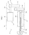
- a flight control surface actuator 10 comprises a three-phase DC motor (hereinafter, referred to as a "drive motor 12") according to this embodiment, a speed reduction mechanism 14, and a linear motion mechanism 16.
- the speed reduction mechanism 14 reduces the rotational speed of a drive shaft 12a of the drive motor 12 at a constant rate.
- the linear motion mechanism 16 converts rotary motion (the speed of which is decreased by the speed reduction mechanism 14) into linear motion.
- the linear motion mechanism 16 uses, for example, a ball screw which comprises a nut 16a and a male threaded shaft 16b.
- the nut 16a is secured to a transmission shaft 14a of the speed reduction mechanism 14.
- the male threaded shaft 16b threadedly engages with the nut 16a.
- the nut 16a rotates along with the transmission shaft 14a of the speed reduction mechanism 14.
- the male threaded shaft 16b moves in a linear motion as the nut 16a rotates.
- An end of the male threaded shaft 16b is connected to a movable flight control surface 20 with a pin.
- the speed reduction mechanism 14 includes a first reduction gear 14c and a second reduction gear 14d.
- the first reduction gear 14c reduces the rotation of a drive gear 14b secured to the drive shaft 12a of the drive motor 12.
- the second reduction gear 14d further reduces the rotation of the first reduction gear 14c.
- the transmission shaft 14a is projected from the second reduction gear 14d.
- the transmission shaft 14a is concentric with the rotation axis of the second reduction gear 14d.
- the male threaded shaft 16b may be connected to the transmission shaft 14a with a pin while the nut 16a may be secured to the movable flight control surface 20.
- the rotation of the transmission shaft 14a brings about the rotation of the male threaded shaft 16b, leading linear motion of the nut 16a which is threadedly engaged with the male threaded shaft 16b.
- the drive motor 12 has a motor body 22 and the drive shaft 12a extending from the motor body 22.
- the drive shaft 12a may be arranged in parallel with, for example, the male threaded shaft 16b of the linear motion mechanism 16.
- the drive shaft 12a may be arranged horizontally.
- the drive shaft 12a and the male threaded shaft 16b may be arranged along the same direction or in different directions, in perspective from the top.
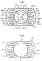
- Fig. 2 is a schematic view of the motor body 22 of the drive motor 12 as seen in the direction of the drive shaft 12a.
- the drive motor 12 shown in Fig. 2 has eight rotor poles as an example.
- the motor body 22 comprises a casing 26 as well as a stator 28 and a rotor 30 which are housed in the casing 26.
- the casing 26 has an oblong shape that is longer than it is wide in one direction (horizontal direction in Fig. 2 ) when viewed in cross section perpendicular to the shaft.
- the casing 26 comprises a pair of side segments at longitudinal extremities 26a positioned at the opposite longitudinal ends thereof, and a pair of parallel segments 26b connecting the side segments at longitudinal extremities 26a with each other.
- Each of the parallel segments 26b is formed to have a flat shape.
- the parallel segments 26b are arranged in parallel to each other and connected to the opposite ends (the upper and lower ends in Fig. 2 ) of the side segments at longitudinal extremities 26a.
- the distance between the parallel segments 26b is smaller than the distance between the side segments at longitudinal extremities 26a.
- one parallel segment 26b forms the upper wall of the casing 26 and the other parallel segment 26b forms the bottom wall of the casing 26.
- Each of the side segments at longitudinal extremities 26a is not limited to a combination of multiple flat pieces connected to each other to form a single segment with internal angles as shown in Fig. 2 . Alternatively, it may have a shape like an arc.
- the stator 28 has a pair of stator units 32.
- the stator units 32 are arranged on both sides of the rotor 30.
- Each stator unit 32 is secured to either of inner walls of the side segments at longitudinal extremities 26a of the casing 26.
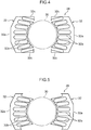
- the stator 28 is integrally formed. More specifically, as shown in Fig. 3 , the stator 28 has a connecting unit 33 that is placed between the stator units 32, 32.
- the connecting unit 33 connects the stator units 32, 32 to integrally form the stator 28.
- the connecting unit 33 may be omitted to provide the stator 28 with a pair of stator units 32 that are spaced apart from each other.
- the stator unit 32 shown in Fig. 4 has triangular units 32c each of which is generally triangular in shape.
- the triangular units 32c are secured to the casing 26 with a slot formed between the units 32c and their respective adjacent core units 32b.
- the stator units 32 shown in Fig. 5 have no triangular unit 32c.
- the stator units 32, 32 have the same shape.
- Each stator unit 32 has a body unit 32a and a number of (seven in this embodiment) core units 32b.
- the body unit 32a contours with the inner surface of the side segment at longitudinal extremities 26a.
- the core unit 32b extends inwardly from the body unit 32a.
- the outer surface of the body unit 32a is joined to the inner surface of the side segment at longitudinal extremities 26a of the casing 26.
- Flat ends of the body unit 32a (the upper and lower end surfaces in Fig. 2 ) are joined to the inner surfaces of the parallel segments 26b, respectively, of the casing 26.
- the entire inner surface of the body unit 32a contours the outer surface of the rotor 30.
- the core units 32b, .., are integrally formed on this inner surface of the body unit 32a.
- the core units 32b, ... are spaced apart from each other at predetermined intervals.
- Each core unit 32b is oblong in the radial direction of the rotor 30 or in the direction slightly oblique to that direction.
- the rotor 30 has a hollow cylindrical shape of a predetermined length in the axial direction of the drive shaft 12a.
- the rotor 30 has alternating poles 30a, ..., around its circumference. More specifically, the rotor 30 is magnetized with alternating poles 30a, ..., of the rotor 30 around its circumference on the radially outer surface thereof.
- the outer surface of the rotor 30 is magnetized with alternating N and S poles around its circumference.
- the "N" and "S” denotations in Fig. 2 indicate that the outer surface is magnetized with the N poles 30a and the S poles 30a.
- the radially inner surface of the magnetic poles 30a denoted by “N” is magnetized with the south pole while the radially inner surface of the magnetic poles 30a denoted by “S” is magnetized with the north pole.
- the rotor 30 may be integrally formed to have a hollow cylindrical shape so that it has alternating poles 30a, ..., around its circumference. Alternatively, a number of magnets may be assembled into a hollow cylinder. The magnets are not necessarily placed on the outer surface.
- the core units 32b are placed so that they are opposite to a part of the circumferential span of the rotor 30. More specifically, the core units 32b are placed only within a range defined by two second virtual planes P2. These second virtual planes P2 are specified respectively by rotating a first virtual plane P1 according to a predetermined angle in the rotor rotating direction or the direction opposite thereto, the first virtual plane P1 being a plane passing through the axial center O of the rotor 30. Accordingly, no core unit 32b is placed in the region outside this range, i.e., a region within the predetermined angular range relative to the direction perpendicular to the first virtual plane P1.
- the stator 28 have neither the connecting unit 33 nor the triangular units 32c (see Fig.
- this region contains no parts of the stator 28.
- the core units 32b coils
- motor torque tends to be lower than a case where the coils are arranged along the entire circumference of the rotor 30.
- the core unit 32b is elongated in the direction of the first virtual plane P1 to increase the number of winds of the coil.
- the first virtual plane P1 is a plane parallel to the parallel segments 26b of the casing 26.
- the second virtual plane P2 is a plane that crosses the first virtual plane P1 at the axial center O of the rotor 30.
- the angle ⁇ between the first virtual plane P1 and the second virtual plane P2 is not limited to a specific value, but is a value not larger than, for example, 70 degrees.
- the casing 26 has the shorter sides in the direction perpendicular to the first virtual plane P1 and the longer sides in the direction parallel to the first virtual plane P1.
- the outer surface of the rotor 30 has eight poles 30a.
- Each one pole 30a is opposed to three core units 32b.
- Each of the poles 30a is formed to be within a range formed when the rotor 30 rotates at an angle of 45 degrees around the axial center of the rotor 30.
- each of the core units 32b with the first virtual plane P1 being placed in the middle thereof can be opposed to one S pole and one N pole.
- Coils 35a, 35b, and 35c are wound around the five core units 32b (except for the outermost core units 32b) through which three phase currents (U-phase current, V-phase current, and W-phase current) are applied.
- the coils 35a, 35b, and 35c are placed within a range defined from the first virtual plane P1 to the two second virtual planes P2 which are specified by rotating through a predetermined angle in the forward and reverse direction of rotation of the rotor 30.
- Auxiliary coils 35d as described below are also placed within this range.
- the coils arez the first coil 35a through which the first phase (e.g. U-phase) current flows, the second coil 35b through which the second phase (e.g., V-phase) current flows, and the third coil 35c through which the third phase (e.g., W-phase) current flows.
- Each of the first coil 35a, the second coil 35b, and the third coil 35c is wound around a bundle of the adjacent three core units 32b (corresponding to one pole) out of the six core units 32b.
- N is equal to or larger than 2
- the coil is wound around a bundle of four or more core units.
- the first coil 35a, the second coil 35b, and the third coil 35c are offset in this order by the amount of one core unit 32b (1/3 pole pitch) in the direction of rotation of the rotor 30.
- the coils 35a, 35b, and 35c are illustrated as they are wound around a part of the core units 32b for the convenient purpose, but the coils 35a, 35b, and 35c are wound around the whole core units 32b.
- the outermost core units 32b have no windings of the coils 35a, 35b, and 35c. Instead, the auxiliary coil 35d is wound around each of the outermost core units 32b.
- the auxiliary coils 35d are the coils other than the coils 35a, 35b, and 35c (a multiple of 3 coils).
- the auxiliary coils 35d are provided to achieve higher torque as compared with a case where only the coils 35a, 35b, and 35c are used.
- the auxiliary coil 35d is wound around a bundle of two or three (or not smaller than three or four when N is equal to or larger than 2) core units 32b including the outermost core units 32b.
- the auxiliary coils 35d illustrated at an upper portion in Fig. 2 are supplied with, for example, the V-phase and W-phase currents.
- the auxiliary coils 35d illustrated at a lower portion in Fig. 2 are supplied with, for example, the U-phase and V-phase currents.
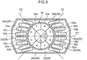
- auxiliary coils 35d contribute to increasing motor torque. If a thinner assembly is required, the outermost core units 32b at both ends in Fig. 2 may be omitted without using any auxiliary coil 35d. In addition, as shown in Fig. 6 , the stator 28 in Fig. 1 may be used without the auxiliary coil 35d.
- the inner surface of the adjacent 3N number of core units 32b is delimited in the width of one pole 30a on the outer surface of the rotor 30. Accordingly, a magnetic effect between the stator 28 and the rotor 30 can be used as the driving force for the rotor 30 when each of the three-phase currents is applied to the coils 35a, 35b, and 35c to generate the magnetic flux around the coils 35a, 35b, and 35c.
- stator units 32 having the coils 35a, 35b, 35c, and 35d are placed only within a range between the second virtual planes P2 which are specified by rotating the first virtual plane P1 through a predetermined angle in the forward and reverse direction of rotation of the rotor 30. Accordingly, the width of the stator 28 in the direction perpendicular to the first virtual plane P1 can be reduced as compared with a case where the stator units 32 as well as the coils 35a, 35b, and 35c are placed along the entire circumference of the rotor 30. As a result, it becomes possible to reduce the thickness of the three-phase DC motor. Thus, a desired output can be obtained without combining an output of another motor.
- so-called distributed winding is used in which the first coil 35a, the second coil 35b, and the third coil 35c are wound around the two or more core units 32b, 32b, ....
- the auxiliary coil 35d is wound around the core units 32b placed at the outermost ends close to the second virtual planes P2 out of the core units 32b, 32b, .... This makes it possible to increase motor torque without enlarging the outer diameter of the stator 28.
- stator 28 and the rotor 30 are housed in the thin casing 26.
- the parallel segments 26b of the casing 26 may be used as the surface used for installation, facilitating more stable installation of the motor.
- the linear motion mechanism 16 and the drive motor 12 are illustrated as being aligned on top of one another.
- the drive motor 12 may be placed in the axial direction of the linear motion mechanism 16.
- so-called distributed winding is used in which the first coil, the second coil, and the third coil are wound around the two or more core units.
- this embodiment can contribute to reducing the thickness of wings without combining torque with any other motor torque.
Landscapes
- Engineering & Computer Science (AREA)
- Power Engineering (AREA)
- Permanent Magnet Type Synchronous Machine (AREA)
- Iron Core Of Rotating Electric Machines (AREA)
- Connection Of Motors, Electrical Generators, Mechanical Devices, And The Like (AREA)
Abstract
Description
- The present invention relates to a three-phase DC motor.
- Conventionally, as disclosed in
U.S. Patent Application Laid-Open No. 2006/0093694 , motor-driven actuators are known. As shown inFig. 7 , the actuator disclosed inU.S. Patent Application Laid-Open No. 2006/0093694 has a ball-screw 63 horizontally mounted under amotor 61 with adrive shaft 61a thereof laid horizontally. Thedrive shaft 61a of themotor 61 and the ball-screw 63 are coupled to each other through aspeed reduction mechanism 65. The ball-screw 63 rotates at a speed reduced at a predetermined rate relative to the rotation speed of themotor 61. Thus, the ball-screw 63 drives a driven unit or units. When the actuator is the one for driving a flight control surface of an aircraft, the driven unit is the flight control surface or a mechanism connected to the flight control surface. - Three-phase DC motors with an inner rotor is known as motors for driving an actuator, as disclosed in, for example, Japanese Patent Application Laid-Open No.
2010-142006 - When the three-phase DC motor with an inner rotor as disclosed in Japanese Patent Application Laid-Open No.
2010-142006 - An object of the present invention is to provide a three-phase DC motor with which the aforementioned problems can be solved. In other words, an object of the present invention is to provide a three-phase DC motor which requires no combination of torque and contributes to reducing the thickness of wings of an aircraft.
- A three-phase DC motor according to an aspect of the present invention comprises: a rotor having a outer surface and magnets; said outer surface of said rotor being configured to have alternating poles of N and S around a circumference of said rotor, a stator including a plurality of core units that are arranged around said rotor and having an inner surface opposite to said outer surface of said rotor; and three or more coils wound around said core units, said coils being placed only within a range defined by second virtual planes, said second virtual planes being specified respectively by rotating a first virtual plane according to a predetermined angle in a rotor rotating direction and a direction opposite thereto, said first virtual plane being a plane passing through the axial center of said rotor, inner surfaces of a adjacent 3N (N = 1, 2, 3, ...) number of core units of said a plurality of core units being delimited within a width of one pole on said outer surface of said rotor.
-
-
Fig. 1 is a schematic view showing a flight control surface actuator in which a three-phase DC motor according to an embodiment of the present invention is mounted; -
Fig. 2 is a schematic view of the three-phase DC motor; -
Fig. 3 is a view showing a stator provided in the three-phase DC motor; -
Fig. 4 is a view showing a variation of a stator; -
Fig. 5 is a view showing another variation of a stator; -
Fig. 6 is a schematic view of a three-phase DC motor according to an aspect where no auxiliary coil is used; and -
Fig. 7 is a cross-sectional view of a conventional actuator. - Now, an embodiment of the present invention is described in detail with reference to the drawings.
- A three-phase DC motor according to an embodiment of the present invention is a motor that serves as a driving source for a flight control surface actuator. This is an inner rotor type three-phase DC motor. The flight control surface actuator is installed in, for example, a wing of an aircraft and is used to swing movable flight control surfaces such as ailerons, elevators, and rudders.
- As shown in
Fig. 1 , a flightcontrol surface actuator 10 comprises a three-phase DC motor (hereinafter, referred to as a "drive motor 12") according to this embodiment, aspeed reduction mechanism 14, and alinear motion mechanism 16. Thespeed reduction mechanism 14 reduces the rotational speed of adrive shaft 12a of thedrive motor 12 at a constant rate. Thelinear motion mechanism 16 converts rotary motion (the speed of which is decreased by the speed reduction mechanism 14) into linear motion. Thelinear motion mechanism 16 uses, for example, a ball screw which comprises anut 16a and a male threadedshaft 16b. Thenut 16a is secured to atransmission shaft 14a of thespeed reduction mechanism 14. The male threadedshaft 16b threadedly engages with thenut 16a. Thenut 16a rotates along with thetransmission shaft 14a of thespeed reduction mechanism 14. The male threadedshaft 16b moves in a linear motion as thenut 16a rotates. An end of the male threadedshaft 16b is connected to a movableflight control surface 20 with a pin. - The
speed reduction mechanism 14 includes afirst reduction gear 14c and asecond reduction gear 14d. Thefirst reduction gear 14c reduces the rotation of adrive gear 14b secured to thedrive shaft 12a of thedrive motor 12. Thesecond reduction gear 14d further reduces the rotation of thefirst reduction gear 14c. Thetransmission shaft 14a is projected from thesecond reduction gear 14d. Thetransmission shaft 14a is concentric with the rotation axis of thesecond reduction gear 14d. - Alternatively, the male threaded
shaft 16b may be connected to thetransmission shaft 14a with a pin while thenut 16a may be secured to the movableflight control surface 20. In this case, the rotation of thetransmission shaft 14a brings about the rotation of the male threadedshaft 16b, leading linear motion of thenut 16a which is threadedly engaged with the male threadedshaft 16b. - The
drive motor 12 has amotor body 22 and thedrive shaft 12a extending from themotor body 22. Thedrive shaft 12a may be arranged in parallel with, for example, the male threadedshaft 16b of thelinear motion mechanism 16. When thedrive motor 12 is mounted within, for example, ahorizontal tail 24, thedrive shaft 12a may be arranged horizontally. Thedrive shaft 12a and the male threadedshaft 16b may be arranged along the same direction or in different directions, in perspective from the top. -
Fig. 2 is a schematic view of themotor body 22 of thedrive motor 12 as seen in the direction of thedrive shaft 12a. Thedrive motor 12 shown inFig. 2 has eight rotor poles as an example. As shown inFig. 2 , themotor body 22 comprises acasing 26 as well as astator 28 and arotor 30 which are housed in thecasing 26. - The
casing 26 has an oblong shape that is longer than it is wide in one direction (horizontal direction inFig. 2 ) when viewed in cross section perpendicular to the shaft. Thecasing 26 comprises a pair of side segments atlongitudinal extremities 26a positioned at the opposite longitudinal ends thereof, and a pair ofparallel segments 26b connecting the side segments atlongitudinal extremities 26a with each other. Each of theparallel segments 26b is formed to have a flat shape. Theparallel segments 26b are arranged in parallel to each other and connected to the opposite ends (the upper and lower ends inFig. 2 ) of the side segments atlongitudinal extremities 26a. Thus, the distance between theparallel segments 26b is smaller than the distance between the side segments atlongitudinal extremities 26a. When thedrive shaft 12a is arranged horizontally as in the case of this embodiment, oneparallel segment 26b forms the upper wall of thecasing 26 and the otherparallel segment 26b forms the bottom wall of thecasing 26. Each of the side segments atlongitudinal extremities 26a is not limited to a combination of multiple flat pieces connected to each other to form a single segment with internal angles as shown inFig. 2 . Alternatively, it may have a shape like an arc. - The
stator 28 has a pair ofstator units 32. Thestator units 32 are arranged on both sides of therotor 30. Eachstator unit 32 is secured to either of inner walls of the side segments atlongitudinal extremities 26a of thecasing 26. - The
stator 28 is integrally formed. More specifically, as shown inFig. 3 , thestator 28 has a connectingunit 33 that is placed between thestator units unit 33 connects thestator units stator 28. As shown inFig. 4 or Fig. 5 , the connectingunit 33 may be omitted to provide thestator 28 with a pair ofstator units 32 that are spaced apart from each other. Of these, thestator unit 32 shown inFig. 4 hastriangular units 32c each of which is generally triangular in shape. Thetriangular units 32c are secured to thecasing 26 with a slot formed between theunits 32c and their respectiveadjacent core units 32b. Thestator units 32 shown inFig. 5 have notriangular unit 32c. - The
stator units stator unit 32 has abody unit 32a and a number of (seven in this embodiment)core units 32b. Thebody unit 32a contours with the inner surface of the side segment atlongitudinal extremities 26a. Thecore unit 32b extends inwardly from thebody unit 32a. The outer surface of thebody unit 32a is joined to the inner surface of the side segment atlongitudinal extremities 26a of thecasing 26. Flat ends of thebody unit 32a (the upper and lower end surfaces inFig. 2 ) are joined to the inner surfaces of theparallel segments 26b, respectively, of thecasing 26. - The entire inner surface of the
body unit 32a contours the outer surface of therotor 30. Thecore units 32b, .., are integrally formed on this inner surface of thebody unit 32a. Thecore units 32b, ... are spaced apart from each other at predetermined intervals. Eachcore unit 32b is oblong in the radial direction of therotor 30 or in the direction slightly oblique to that direction. - The
rotor 30 has a hollow cylindrical shape of a predetermined length in the axial direction of thedrive shaft 12a. Therotor 30 has alternatingpoles 30a, ..., around its circumference. More specifically, therotor 30 is magnetized with alternatingpoles 30a, ..., of therotor 30 around its circumference on the radially outer surface thereof. Thus, the outer surface of therotor 30 is magnetized with alternating N and S poles around its circumference. The "N" and "S" denotations inFig. 2 indicate that the outer surface is magnetized with theN poles 30a and theS poles 30a. Thus, the radially inner surface of themagnetic poles 30a denoted by "N" is magnetized with the south pole while the radially inner surface of themagnetic poles 30a denoted by "S" is magnetized with the north pole. Therotor 30 may be integrally formed to have a hollow cylindrical shape so that it has alternatingpoles 30a, ..., around its circumference. Alternatively, a number of magnets may be assembled into a hollow cylinder. The magnets are not necessarily placed on the outer surface. - The
core units 32b are placed so that they are opposite to a part of the circumferential span of therotor 30. More specifically, thecore units 32b are placed only within a range defined by two second virtual planes P2. These second virtual planes P2 are specified respectively by rotating a first virtual plane P1 according to a predetermined angle in the rotor rotating direction or the direction opposite thereto, the first virtual plane P1 being a plane passing through the axial center O of therotor 30. Accordingly, nocore unit 32b is placed in the region outside this range, i.e., a region within the predetermined angular range relative to the direction perpendicular to the first virtual plane P1. When thestator 28 have neither the connectingunit 33 nor thetriangular units 32c (seeFig. 5 ), this region contains no parts of thestator 28. In cases where thecore units 32b (coils) are placed only within the region that is formed when the rotor rotates at a predetermined angle around the axial center of the rotor, motor torque tends to be lower than a case where the coils are arranged along the entire circumference of therotor 30. In order to compensate for this, thecore unit 32b is elongated in the direction of the first virtual plane P1 to increase the number of winds of the coil. - The first virtual plane P1 is a plane parallel to the
parallel segments 26b of thecasing 26. The second virtual plane P2 is a plane that crosses the first virtual plane P1 at the axial center O of therotor 30. The angle θ between the first virtual plane P1 and the second virtual plane P2 is not limited to a specific value, but is a value not larger than, for example, 70 degrees. Thecasing 26 has the shorter sides in the direction perpendicular to the first virtual plane P1 and the longer sides in the direction parallel to the first virtual plane P1. - In this embodiment, the outer surface of the
rotor 30 has eightpoles 30a. Each onepole 30a is opposed to threecore units 32b. Each of thepoles 30a is formed to be within a range formed when therotor 30 rotates at an angle of 45 degrees around the axial center of therotor 30. In thestator units 32, each of thecore units 32b with the first virtual plane P1 being placed in the middle thereof can be opposed to one S pole and one N pole.Coils core units 32b (except for theoutermost core units 32b) through which three phase currents (U-phase current, V-phase current, and W-phase current) are applied. In other words, thecoils rotor 30.Auxiliary coils 35d as described below are also placed within this range. - It should be noted that the
rotor 30 is not limited to the one having eightpoles 30a on the outer surface thereof. It may have even number ofpoles 30a, such as six, ten, or 12 poles in which the number herein is not smaller than 6. It is not limited that onepole 30a is opposed to the threecore units 32b. Alternatively, onepole 30a may be opposed to a multiple of 3core units 32b, i.e., 3N (N = 1, 2, ...)core units 32b. - The coils arez the
first coil 35a through which the first phase (e.g. U-phase) current flows, thesecond coil 35b through which the second phase (e.g., V-phase) current flows, and thethird coil 35c through which the third phase (e.g., W-phase) current flows. Each of thefirst coil 35a, thesecond coil 35b, and thethird coil 35c is wound around a bundle of the adjacent threecore units 32b (corresponding to one pole) out of the sixcore units 32b. When the core units are increased (N is equal to or larger than 2), the coil is wound around a bundle of four or more core units. Thefirst coil 35a, thesecond coil 35b, and thethird coil 35c are offset in this order by the amount of onecore unit 32b (1/3 pole pitch) in the direction of rotation of therotor 30. - It should be noted that, in
Fig. 2 , thecoils core units 32b for the convenient purpose, but thecoils whole core units 32b. - The
outermost core units 32b have no windings of thecoils auxiliary coil 35d is wound around each of theoutermost core units 32b. - The
auxiliary coils 35d are the coils other than thecoils auxiliary coils 35d are provided to achieve higher torque as compared with a case where only thecoils auxiliary coil 35d is wound around a bundle of two or three (or not smaller than three or four when N is equal to or larger than 2)core units 32b including theoutermost core units 32b. Theauxiliary coils 35d illustrated at an upper portion inFig. 2 are supplied with, for example, the V-phase and W-phase currents. Theauxiliary coils 35d illustrated at a lower portion inFig. 2 are supplied with, for example, the U-phase and V-phase currents. Theauxiliary coils 35d contribute to increasing motor torque. If a thinner assembly is required, theoutermost core units 32b at both ends inFig. 2 may be omitted without using anyauxiliary coil 35d. In addition, as shown inFig. 6 , thestator 28 inFig. 1 may be used without theauxiliary coil 35d. - As described above, in the
drive motor 12 according to this embodiment, the inner surface of the adjacent 3N number ofcore units 32b is delimited in the width of onepole 30a on the outer surface of therotor 30. Accordingly, a magnetic effect between thestator 28 and therotor 30 can be used as the driving force for therotor 30 when each of the three-phase currents is applied to thecoils coils stator units 32 having thecoils rotor 30. Accordingly, the width of thestator 28 in the direction perpendicular to the first virtual plane P1 can be reduced as compared with a case where thestator units 32 as well as thecoils rotor 30. As a result, it becomes possible to reduce the thickness of the three-phase DC motor. Thus, a desired output can be obtained without combining an output of another motor. - In addition, in this embodiment, so-called distributed winding is used in which the
first coil 35a, thesecond coil 35b, and thethird coil 35c are wound around the two ormore core units - Moreover, in this embodiment, the
auxiliary coil 35d is wound around thecore units 32b placed at the outermost ends close to the second virtual planes P2 out of thecore units stator 28. - Furthermore, in this embodiment, the
stator 28 and therotor 30 are housed in thethin casing 26. Theparallel segments 26b of thecasing 26 may be used as the surface used for installation, facilitating more stable installation of the motor. - It should be noted that the present invention is not limited to the embodiment, and various changes and modifications can be made without departing from the scope and spirit thereof.
- In the embodiment, the
linear motion mechanism 16 and thedrive motor 12 are illustrated as being aligned on top of one another. However, this is not the only embodiment. For example, thedrive motor 12 may be placed in the axial direction of thelinear motion mechanism 16. - Now, the embodiment is summarized.
- (1) In this embodiment, the inner surface of the adjacent 3N number of core units is delimited in the width of one pole on the rotor. Accordingly, a magnetic effect between the stator and the rotor can be used as the driving force for the rotor when each of the three-phase currents is applied to the coils to generate the magnetic flux around the coils Furthermore, the coils are placed only within a range between the second virtual planes which are specified by rotating the first virtual plane through a predetermined angle in the forward and reverse direction of rotation of the rotor. Accordingly, the width of the stator in the direction perpendicular to the first virtual plane can be reduced as compared with a case where the coils are placed along the entire circumference of the rotor. As a result, it becomes possible to reduce the thickness of the three-phase DC motor. Thus, a desired output can be obtained without combining an output of another motor.
- (2) The three or more coils may include the first coil through which the first phase current flows, the second coil through which the second phase current flows, and the third coil through which the third phase current flows. In this case, the first coil, the second coil, and the third coil are each wound around a bundle of the adjacent core units. The first coil, the second coil, and the third coil may be offset in this order by 1/3 pole pitch in the direction of rotation of the rotor.
- In this aspect, so-called distributed winding is used in which the first coil, the second coil, and the third coil are wound around the two or more core units. This reduces torque ripple and allows relatively smooth driving without any special measure to the shape of teeth, the shape of the rotor, and a method of applying current. Accordingly, it is possible to reduce vibration and noise. Even with a high power motor, it is possible to reduce vibration and noise and improve reliability.
- (3) The auxiliary coil may be wound around at least core units placed at outermost ends on a side of the second virtual planes out of the core units.
- In this aspect, it is possible to increase motor torque without enlarging the outer diameter of the stator.
- (4) The three-phase DC motor may have the casing in which the stator and the rotor are housed. In this case, the casing may have sides shorter in the direction perpendicular to the first virtual plane than sides in the direction parallel to the first virtual plane. In this aspect, the stator and the rotor are housed in the thin casing.
- (5) The three-phase DC motor may be configured as a driving source for the flight control surface actuator.
- As described above, this embodiment can contribute to reducing the thickness of wings without combining torque with any other motor torque.
- This application is based on Japanese Patent application No.
2011-010036 - Although the present invention has been fully described by way of example with reference to the accompanying drawings, it is to be understood that various changes and modifications will be apparent to those skilled in the art. Therefore, unless otherwise such changes and modifications depart from the scope of the present invention hereinafter defined, they should be construed as being included therein.
Claims (5)
- A three-phase DC motor comprising:a rotor having a outer surface and magnets; said outer surface of said rotor being configured to have alternating poles ofN and S around a circumference of said rotor,a stator including a plurality of core units that are arranged around said rotor and having an inner surface opposite to said outer surface of said rotor; andthree or more coils wound around said core units, said coils being placed only within a range defined by second virtual planes, said second virtual planes being specified respectively by rotating a first virtual plane according to a predetermined angle in a rotor rotating direction and a direction opposite thereto, said first virtual plane being a plane passing through the axial center of said rotor,inner surfaces of a adjacent 3N (N = 1, 2, 3, ...) number of core units of said a plurality of said core units being delimited within a width of one pole on said outer surface of said rotor.
- The three-phase DC motor as claimed in Claim 1, wherein:said three or more coils include a first coil through which a first phase current flows, a second coil through which a second phase current flows, and a third coil through which a third phase current flows,said first coil, said second coil, and said third coil are each wound around a bundle of adjacent core units, andsaid first coil, said second coil, and said third coil are offset in this order by 1/3 pole pitch in the rotor rotating direction.
- The three-phase DC motor as claimed in Claim 1 or 2, wherein
an auxiliary coil is wound around at least core units placed at outermost ends on a side of said second virtual planes, out of said core units. - The three-phase DC motor as claimed in any one of Claims 1 to 3, further comprising a casing in which said stator and said rotor are housed, wherein
said casing has sides shorter in the direction perpendicular to said first virtual plane than sides in the direction parallel to said first virtual plane. - The three-phase DC motor as claimed in any one of Claims 1 to 4, wherein the three-phase DC motor is configured as a driving source for a flight control surface actuator.
Applications Claiming Priority (1)
| Application Number | Priority Date | Filing Date | Title |
|---|---|---|---|
| JP2011010036A JP5739172B2 (en) | 2011-01-20 | 2011-01-20 | Motor and aircraft control surface drive actuator |
Publications (2)
| Publication Number | Publication Date |
|---|---|
| EP2479870A1 true EP2479870A1 (en) | 2012-07-25 |
| EP2479870B1 EP2479870B1 (en) | 2015-11-18 |
Family
ID=45554455
Family Applications (1)
| Application Number | Title | Priority Date | Filing Date |
|---|---|---|---|
| EP12000306.6A Active EP2479870B1 (en) | 2011-01-20 | 2012-01-18 | Three-phase DC motor |
Country Status (3)
| Country | Link |
|---|---|
| US (1) | US8618711B2 (en) |
| EP (1) | EP2479870B1 (en) |
| JP (1) | JP5739172B2 (en) |
Families Citing this family (4)
| Publication number | Priority date | Publication date | Assignee | Title |
|---|---|---|---|---|
| CN104953728B (en) * | 2014-03-28 | 2019-07-09 | 德昌电机(深圳)有限公司 | Polygon stator core and motor including it |
| US10680497B2 (en) * | 2014-10-23 | 2020-06-09 | Robert Bosch Gmbh | Fluid-cooled housing for an electrical machine |
| JP6301521B1 (en) * | 2016-12-14 | 2018-03-28 | 株式会社ミスミ | Stator core, stepping motor and linear actuator |
| WO2020113056A1 (en) | 2018-11-29 | 2020-06-04 | Milwaukee Electric Tool Corporation | Motor winding design for an electric motor |
Citations (5)
| Publication number | Priority date | Publication date | Assignee | Title |
|---|---|---|---|---|
| DE1964900A1 (en) * | 1969-12-24 | 1971-07-01 | Licentia Gmbh | Single-phase induction motor with a stand flattened symmetrically to a center line |
| WO2000062400A1 (en) * | 1999-04-09 | 2000-10-19 | Motor Power Company S.R.L. | Brushless synchronous electric motor |
| US20060093694A1 (en) | 2004-11-03 | 2006-05-04 | Moog Inc. | Electro-mechanical injection actuator for controllably rotating and translating the feedscrew of a single-stage injection molding machine |
| US20090134738A1 (en) * | 2005-11-28 | 2009-05-28 | Matsushita Electric Industrial Co., Ltd. | Motor and apparatus employing the same |
| JP2010142006A (en) | 2008-12-11 | 2010-06-24 | Asmo Co Ltd | Motor |
Family Cites Families (7)
| Publication number | Priority date | Publication date | Assignee | Title |
|---|---|---|---|---|
| US3783318A (en) * | 1972-10-06 | 1974-01-01 | Marathon Electric Mfg | Laminated stator core for dynamoelectric machines |
| JPH04340338A (en) * | 1991-05-13 | 1992-11-26 | Fujitsu General Ltd | Stator core for motor |
| EP0771061B1 (en) * | 1995-10-25 | 2003-05-07 | Sawafuji Electric Co., Ltd. | Small generator |
| JP2004353521A (en) * | 2003-05-28 | 2004-12-16 | Matsushita Electric Ind Co Ltd | Hermetic compressor |
| JP4285137B2 (en) * | 2003-07-23 | 2009-06-24 | ダイキン工業株式会社 | Fluid machinery |
| JP4821770B2 (en) * | 2005-07-19 | 2011-11-24 | 株式会社デンソー | AC motor and its control device |
| DE102009049525A1 (en) | 2008-10-16 | 2010-05-20 | Asmo Co., Ltd., Kosai-shi | engine |
-
2011
- 2011-01-20 JP JP2011010036A patent/JP5739172B2/en active Active
-
2012
- 2012-01-18 EP EP12000306.6A patent/EP2479870B1/en active Active
- 2012-01-18 US US13/352,700 patent/US8618711B2/en active Active
Patent Citations (5)
| Publication number | Priority date | Publication date | Assignee | Title |
|---|---|---|---|---|
| DE1964900A1 (en) * | 1969-12-24 | 1971-07-01 | Licentia Gmbh | Single-phase induction motor with a stand flattened symmetrically to a center line |
| WO2000062400A1 (en) * | 1999-04-09 | 2000-10-19 | Motor Power Company S.R.L. | Brushless synchronous electric motor |
| US20060093694A1 (en) | 2004-11-03 | 2006-05-04 | Moog Inc. | Electro-mechanical injection actuator for controllably rotating and translating the feedscrew of a single-stage injection molding machine |
| US20090134738A1 (en) * | 2005-11-28 | 2009-05-28 | Matsushita Electric Industrial Co., Ltd. | Motor and apparatus employing the same |
| JP2010142006A (en) | 2008-12-11 | 2010-06-24 | Asmo Co Ltd | Motor |
Also Published As
| Publication number | Publication date |
|---|---|
| US8618711B2 (en) | 2013-12-31 |
| JP2012152062A (en) | 2012-08-09 |
| EP2479870B1 (en) | 2015-11-18 |
| US20120187798A1 (en) | 2012-07-26 |
| JP5739172B2 (en) | 2015-06-24 |
Similar Documents
| Publication | Publication Date | Title |
|---|---|---|
| US8324779B2 (en) | Motor | |
| CN104022609B (en) | Novel double-stator lowripple torque stepping motor | |
| EP3121939B1 (en) | Electric motor, electric power steering device, and vehicle | |
| EP2840680B1 (en) | System and method for reducing torque ripple in an interior permanent magnet motor | |
| KR20020053709A (en) | A rotary electromechanical device and a pulley driving system using the rotary electromechanical device | |
| BR112015028472B1 (en) | Aircraft with at least one synchronous reluctance machine | |
| CN109428407B (en) | Stator core | |
| US8618711B2 (en) | Three-phase DC motor | |
| WO2015152372A1 (en) | Double-stator switched reluctance dynamo | |
| US20130187501A1 (en) | Electric motor assembly with electric phasing of rotor segments to reduce back electromotive force | |
| US20190312476A1 (en) | Motor | |
| US20110025156A1 (en) | Machine for fixing | |
| CN100468914C (en) | rotating electrical machine | |
| EP0226586A1 (en) | A synchronous servomotor. | |
| WO2014192609A1 (en) | Inner rotor brushless motor | |
| US20130320798A1 (en) | System and method for reducing cogging torque in an interior permanent magnet motor | |
| CN103891110A (en) | Drive device | |
| CN103891109B (en) | Driving means | |
| US10707705B2 (en) | Motor with a stator having salient poles and method of manufacturing the motor | |
| JP7348829B2 (en) | Hoisting machine and elevator | |
| WO2018123830A1 (en) | Dynamo-electric machine | |
| JP7361914B2 (en) | Electromagnetic equipment and aircraft using electromagnetic equipment | |
| JP5097989B2 (en) | Spiral motor and method for manufacturing spiral motor | |
| EP2474081A1 (en) | Transverse flux electrical motor | |
| WO2012071569A2 (en) | Virtual pole electric motor |
Legal Events
| Date | Code | Title | Description |
|---|---|---|---|
| PUAI | Public reference made under article 153(3) epc to a published international application that has entered the european phase |
Free format text: ORIGINAL CODE: 0009012 |
|
| AK | Designated contracting states |
Kind code of ref document: A1 Designated state(s): AL AT BE BG CH CY CZ DE DK EE ES FI FR GB GR HR HU IE IS IT LI LT LU LV MC MK MT NL NO PL PT RO RS SE SI SK SM TR |
|
| AX | Request for extension of the european patent |
Extension state: BA ME |
|
| 17P | Request for examination filed |
Effective date: 20130124 |
|
| GRAP | Despatch of communication of intention to grant a patent |
Free format text: ORIGINAL CODE: EPIDOSNIGR1 |
|
| INTG | Intention to grant announced |
Effective date: 20150528 |
|
| RIN1 | Information on inventor provided before grant (corrected) |
Inventor name: SHIRAI, YASUYUKI |
|
| GRAS | Grant fee paid |
Free format text: ORIGINAL CODE: EPIDOSNIGR3 |
|
| GRAA | (expected) grant |
Free format text: ORIGINAL CODE: 0009210 |
|
| AK | Designated contracting states |
Kind code of ref document: B1 Designated state(s): AL AT BE BG CH CY CZ DE DK EE ES FI FR GB GR HR HU IE IS IT LI LT LU LV MC MK MT NL NO PL PT RO RS SE SI SK SM TR |
|
| REG | Reference to a national code |
Ref country code: GB Ref legal event code: FG4D |
|
| REG | Reference to a national code |
Ref country code: CH Ref legal event code: EP |
|
| REG | Reference to a national code |
Ref country code: AT Ref legal event code: REF Ref document number: 761983 Country of ref document: AT Kind code of ref document: T Effective date: 20151215 |
|
| REG | Reference to a national code |
Ref country code: IE Ref legal event code: FG4D |
|
| REG | Reference to a national code |
Ref country code: FR Ref legal event code: PLFP Year of fee payment: 5 |
|
| REG | Reference to a national code |
Ref country code: DE Ref legal event code: R096 Ref document number: 602012012269 Country of ref document: DE |
|
| REG | Reference to a national code |
Ref country code: NL Ref legal event code: MP Effective date: 20160218 |
|
| REG | Reference to a national code |
Ref country code: LT Ref legal event code: MG4D |
|
| REG | Reference to a national code |
Ref country code: AT Ref legal event code: MK05 Ref document number: 761983 Country of ref document: AT Kind code of ref document: T Effective date: 20151118 |
|
| PG25 | Lapsed in a contracting state [announced via postgrant information from national office to epo] |
Ref country code: HR Free format text: LAPSE BECAUSE OF FAILURE TO SUBMIT A TRANSLATION OF THE DESCRIPTION OR TO PAY THE FEE WITHIN THE PRESCRIBED TIME-LIMIT Effective date: 20151118 Ref country code: NO Free format text: LAPSE BECAUSE OF FAILURE TO SUBMIT A TRANSLATION OF THE DESCRIPTION OR TO PAY THE FEE WITHIN THE PRESCRIBED TIME-LIMIT Effective date: 20160218 Ref country code: IT Free format text: LAPSE BECAUSE OF FAILURE TO SUBMIT A TRANSLATION OF THE DESCRIPTION OR TO PAY THE FEE WITHIN THE PRESCRIBED TIME-LIMIT Effective date: 20151118 Ref country code: LT Free format text: LAPSE BECAUSE OF FAILURE TO SUBMIT A TRANSLATION OF THE DESCRIPTION OR TO PAY THE FEE WITHIN THE PRESCRIBED TIME-LIMIT Effective date: 20151118 Ref country code: ES Free format text: LAPSE BECAUSE OF FAILURE TO SUBMIT A TRANSLATION OF THE DESCRIPTION OR TO PAY THE FEE WITHIN THE PRESCRIBED TIME-LIMIT Effective date: 20151118 Ref country code: IS Free format text: LAPSE BECAUSE OF FAILURE TO SUBMIT A TRANSLATION OF THE DESCRIPTION OR TO PAY THE FEE WITHIN THE PRESCRIBED TIME-LIMIT Effective date: 20160318 Ref country code: NL Free format text: LAPSE BECAUSE OF FAILURE TO SUBMIT A TRANSLATION OF THE DESCRIPTION OR TO PAY THE FEE WITHIN THE PRESCRIBED TIME-LIMIT Effective date: 20151118 |
|
| PG25 | Lapsed in a contracting state [announced via postgrant information from national office to epo] |
Ref country code: BE Free format text: LAPSE BECAUSE OF NON-PAYMENT OF DUE FEES Effective date: 20160131 Ref country code: LV Free format text: LAPSE BECAUSE OF FAILURE TO SUBMIT A TRANSLATION OF THE DESCRIPTION OR TO PAY THE FEE WITHIN THE PRESCRIBED TIME-LIMIT Effective date: 20151118 Ref country code: SE Free format text: LAPSE BECAUSE OF FAILURE TO SUBMIT A TRANSLATION OF THE DESCRIPTION OR TO PAY THE FEE WITHIN THE PRESCRIBED TIME-LIMIT Effective date: 20151118 Ref country code: AT Free format text: LAPSE BECAUSE OF FAILURE TO SUBMIT A TRANSLATION OF THE DESCRIPTION OR TO PAY THE FEE WITHIN THE PRESCRIBED TIME-LIMIT Effective date: 20151118 Ref country code: PT Free format text: LAPSE BECAUSE OF FAILURE TO SUBMIT A TRANSLATION OF THE DESCRIPTION OR TO PAY THE FEE WITHIN THE PRESCRIBED TIME-LIMIT Effective date: 20160318 Ref country code: PL Free format text: LAPSE BECAUSE OF FAILURE TO SUBMIT A TRANSLATION OF THE DESCRIPTION OR TO PAY THE FEE WITHIN THE PRESCRIBED TIME-LIMIT Effective date: 20151118 Ref country code: RS Free format text: LAPSE BECAUSE OF FAILURE TO SUBMIT A TRANSLATION OF THE DESCRIPTION OR TO PAY THE FEE WITHIN THE PRESCRIBED TIME-LIMIT Effective date: 20151118 Ref country code: FI Free format text: LAPSE BECAUSE OF FAILURE TO SUBMIT A TRANSLATION OF THE DESCRIPTION OR TO PAY THE FEE WITHIN THE PRESCRIBED TIME-LIMIT Effective date: 20151118 Ref country code: GR Free format text: LAPSE BECAUSE OF FAILURE TO SUBMIT A TRANSLATION OF THE DESCRIPTION OR TO PAY THE FEE WITHIN THE PRESCRIBED TIME-LIMIT Effective date: 20160219 |
|
| PG25 | Lapsed in a contracting state [announced via postgrant information from national office to epo] |
Ref country code: CZ Free format text: LAPSE BECAUSE OF FAILURE TO SUBMIT A TRANSLATION OF THE DESCRIPTION OR TO PAY THE FEE WITHIN THE PRESCRIBED TIME-LIMIT Effective date: 20151118 |
|
| REG | Reference to a national code |
Ref country code: DE Ref legal event code: R097 Ref document number: 602012012269 Country of ref document: DE |
|
| PG25 | Lapsed in a contracting state [announced via postgrant information from national office to epo] |
Ref country code: EE Free format text: LAPSE BECAUSE OF FAILURE TO SUBMIT A TRANSLATION OF THE DESCRIPTION OR TO PAY THE FEE WITHIN THE PRESCRIBED TIME-LIMIT Effective date: 20151118 Ref country code: DK Free format text: LAPSE BECAUSE OF FAILURE TO SUBMIT A TRANSLATION OF THE DESCRIPTION OR TO PAY THE FEE WITHIN THE PRESCRIBED TIME-LIMIT Effective date: 20151118 Ref country code: LU Free format text: LAPSE BECAUSE OF FAILURE TO SUBMIT A TRANSLATION OF THE DESCRIPTION OR TO PAY THE FEE WITHIN THE PRESCRIBED TIME-LIMIT Effective date: 20160118 Ref country code: RO Free format text: LAPSE BECAUSE OF FAILURE TO SUBMIT A TRANSLATION OF THE DESCRIPTION OR TO PAY THE FEE WITHIN THE PRESCRIBED TIME-LIMIT Effective date: 20151118 Ref country code: SK Free format text: LAPSE BECAUSE OF FAILURE TO SUBMIT A TRANSLATION OF THE DESCRIPTION OR TO PAY THE FEE WITHIN THE PRESCRIBED TIME-LIMIT Effective date: 20151118 Ref country code: SM Free format text: LAPSE BECAUSE OF FAILURE TO SUBMIT A TRANSLATION OF THE DESCRIPTION OR TO PAY THE FEE WITHIN THE PRESCRIBED TIME-LIMIT Effective date: 20151118 |
|
| REG | Reference to a national code |
Ref country code: CH Ref legal event code: PL |
|
| PLBE | No opposition filed within time limit |
Free format text: ORIGINAL CODE: 0009261 |
|
| STAA | Information on the status of an ep patent application or granted ep patent |
Free format text: STATUS: NO OPPOSITION FILED WITHIN TIME LIMIT |
|
| PG25 | Lapsed in a contracting state [announced via postgrant information from national office to epo] |
Ref country code: MC Free format text: LAPSE BECAUSE OF FAILURE TO SUBMIT A TRANSLATION OF THE DESCRIPTION OR TO PAY THE FEE WITHIN THE PRESCRIBED TIME-LIMIT Effective date: 20151118 |
|
| 26N | No opposition filed |
Effective date: 20160819 |
|
| GBPC | Gb: european patent ceased through non-payment of renewal fee |
Effective date: 20160218 |
|
| PG25 | Lapsed in a contracting state [announced via postgrant information from national office to epo] |
Ref country code: CH Free format text: LAPSE BECAUSE OF NON-PAYMENT OF DUE FEES Effective date: 20160131 Ref country code: LI Free format text: LAPSE BECAUSE OF NON-PAYMENT OF DUE FEES Effective date: 20160131 |
|
| REG | Reference to a national code |
Ref country code: IE Ref legal event code: MM4A |
|
| PG25 | Lapsed in a contracting state [announced via postgrant information from national office to epo] |
Ref country code: SI Free format text: LAPSE BECAUSE OF FAILURE TO SUBMIT A TRANSLATION OF THE DESCRIPTION OR TO PAY THE FEE WITHIN THE PRESCRIBED TIME-LIMIT Effective date: 20151118 |
|
| PG25 | Lapsed in a contracting state [announced via postgrant information from national office to epo] |
Ref country code: BE Free format text: LAPSE BECAUSE OF FAILURE TO SUBMIT A TRANSLATION OF THE DESCRIPTION OR TO PAY THE FEE WITHIN THE PRESCRIBED TIME-LIMIT Effective date: 20151118 |
|
| REG | Reference to a national code |
Ref country code: FR Ref legal event code: PLFP Year of fee payment: 6 |
|
| PG25 | Lapsed in a contracting state [announced via postgrant information from national office to epo] |
Ref country code: IE Free format text: LAPSE BECAUSE OF NON-PAYMENT OF DUE FEES Effective date: 20160118 Ref country code: GB Free format text: LAPSE BECAUSE OF NON-PAYMENT OF DUE FEES Effective date: 20160218 |
|
| PG25 | Lapsed in a contracting state [announced via postgrant information from national office to epo] |
Ref country code: MT Free format text: LAPSE BECAUSE OF FAILURE TO SUBMIT A TRANSLATION OF THE DESCRIPTION OR TO PAY THE FEE WITHIN THE PRESCRIBED TIME-LIMIT Effective date: 20151118 |
|
| REG | Reference to a national code |
Ref country code: FR Ref legal event code: PLFP Year of fee payment: 7 |
|
| PG25 | Lapsed in a contracting state [announced via postgrant information from national office to epo] |
Ref country code: CY Free format text: LAPSE BECAUSE OF FAILURE TO SUBMIT A TRANSLATION OF THE DESCRIPTION OR TO PAY THE FEE WITHIN THE PRESCRIBED TIME-LIMIT Effective date: 20151118 Ref country code: HU Free format text: LAPSE BECAUSE OF FAILURE TO SUBMIT A TRANSLATION OF THE DESCRIPTION OR TO PAY THE FEE WITHIN THE PRESCRIBED TIME-LIMIT; INVALID AB INITIO Effective date: 20120118 |
|
| PG25 | Lapsed in a contracting state [announced via postgrant information from national office to epo] |
Ref country code: MT Free format text: LAPSE BECAUSE OF FAILURE TO SUBMIT A TRANSLATION OF THE DESCRIPTION OR TO PAY THE FEE WITHIN THE PRESCRIBED TIME-LIMIT Effective date: 20160131 Ref country code: MK Free format text: LAPSE BECAUSE OF FAILURE TO SUBMIT A TRANSLATION OF THE DESCRIPTION OR TO PAY THE FEE WITHIN THE PRESCRIBED TIME-LIMIT Effective date: 20151118 Ref country code: TR Free format text: LAPSE BECAUSE OF FAILURE TO SUBMIT A TRANSLATION OF THE DESCRIPTION OR TO PAY THE FEE WITHIN THE PRESCRIBED TIME-LIMIT Effective date: 20151118 |
|
| PG25 | Lapsed in a contracting state [announced via postgrant information from national office to epo] |
Ref country code: BG Free format text: LAPSE BECAUSE OF FAILURE TO SUBMIT A TRANSLATION OF THE DESCRIPTION OR TO PAY THE FEE WITHIN THE PRESCRIBED TIME-LIMIT Effective date: 20151118 |
|
| PG25 | Lapsed in a contracting state [announced via postgrant information from national office to epo] |
Ref country code: AL Free format text: LAPSE BECAUSE OF FAILURE TO SUBMIT A TRANSLATION OF THE DESCRIPTION OR TO PAY THE FEE WITHIN THE PRESCRIBED TIME-LIMIT Effective date: 20151118 |
|
| P01 | Opt-out of the competence of the unified patent court (upc) registered |
Effective date: 20230615 |
|
| PGFP | Annual fee paid to national office [announced via postgrant information from national office to epo] |
Ref country code: DE Payment date: 20250121 Year of fee payment: 14 |
|
| PGFP | Annual fee paid to national office [announced via postgrant information from national office to epo] |
Ref country code: FR Payment date: 20250127 Year of fee payment: 14 |