EP2479864A1 - Secondary battery pack system - Google Patents
Secondary battery pack system Download PDFInfo
- Publication number
- EP2479864A1 EP2479864A1 EP09849418A EP09849418A EP2479864A1 EP 2479864 A1 EP2479864 A1 EP 2479864A1 EP 09849418 A EP09849418 A EP 09849418A EP 09849418 A EP09849418 A EP 09849418A EP 2479864 A1 EP2479864 A1 EP 2479864A1
- Authority
- EP
- European Patent Office
- Prior art keywords
- battery pack
- main body
- control signal
- discharge control
- body side
- Prior art date
- Legal status (The legal status is an assumption and is not a legal conclusion. Google has not performed a legal analysis and makes no representation as to the accuracy of the status listed.)
- Granted
Links
Images


Classifications
-
- H—ELECTRICITY
- H02—GENERATION; CONVERSION OR DISTRIBUTION OF ELECTRIC POWER
- H02J—ELECTRIC POWER NETWORKS; CIRCUIT ARRANGEMENTS OR SYSTEMS FOR SUPPLYING OR DISTRIBUTING ELECTRIC POWER; SYSTEMS FOR STORING ELECTRIC ENERGY
- H02J7/00—Circuit arrangements for charging or discharging batteries or for supplying loads from batteries
- H02J7/50—Circuit arrangements for charging or discharging batteries or for supplying loads from batteries acting upon multiple batteries simultaneously or sequentially
-
- H—ELECTRICITY
- H02—GENERATION; CONVERSION OR DISTRIBUTION OF ELECTRIC POWER
- H02J—ELECTRIC POWER NETWORKS; CIRCUIT ARRANGEMENTS OR SYSTEMS FOR SUPPLYING OR DISTRIBUTING ELECTRIC POWER; SYSTEMS FOR STORING ELECTRIC ENERGY
- H02J7/00—Circuit arrangements for charging or discharging batteries or for supplying loads from batteries
- H02J7/60—Circuit arrangements for charging or discharging batteries or for supplying loads from batteries including safety or protection arrangements
- H02J7/663—Circuit arrangements for charging or discharging batteries or for supplying loads from batteries including safety or protection arrangements using battery or load disconnect circuits
-
- H—ELECTRICITY
- H02—GENERATION; CONVERSION OR DISTRIBUTION OF ELECTRIC POWER
- H02J—ELECTRIC POWER NETWORKS; CIRCUIT ARRANGEMENTS OR SYSTEMS FOR SUPPLYING OR DISTRIBUTING ELECTRIC POWER; SYSTEMS FOR STORING ELECTRIC ENERGY
- H02J7/00—Circuit arrangements for charging or discharging batteries or for supplying loads from batteries
- H02J7/80—Circuit arrangements for charging or discharging batteries or for supplying loads from batteries including monitoring or indicating arrangements
-
- H—ELECTRICITY
- H02—GENERATION; CONVERSION OR DISTRIBUTION OF ELECTRIC POWER
- H02J—ELECTRIC POWER NETWORKS; CIRCUIT ARRANGEMENTS OR SYSTEMS FOR SUPPLYING OR DISTRIBUTING ELECTRIC POWER; SYSTEMS FOR STORING ELECTRIC ENERGY
- H02J7/00—Circuit arrangements for charging or discharging batteries or for supplying loads from batteries
- H02J7/90—Regulation of charging or discharging current or voltage
Definitions
- the present invention relates to a secondary battery pack system for supplying power to an electronic device, etc., and, more particularly, to a secondary battery pack system in which a plurality of battery packs can be connected in parallel.
- a conventional system capable of using secondary battery packs connected in parallel has a configuration in which a diode is used for each battery pack to prevent backflow of electricity for parallel connection or a control signal is issued from a system main body so as to cause each battery pack to discharge its energy.
- PTL 1 JP-A-2004-229391 discloses a battery pack having first and second battery blocks each in which a plurality of secondary batteries are connected in series and in parallel, one battery terminal to which one terminals of the first and second battery blocks are connected respectively via first and second switch means, the other battery terminal to which the other terminals of the first and second battery blocks are connected, a switch means for switching the first and second switch means when charging or discharging is carried out, a capacity detection means for detecting the capacity of each of the batteries in the first and second battery blocks, and a switch control means for controlling the switch means depending on the detected battery capacity, and when the first and second switch means are switched, after elapse of a predetermined time when one of the first and second switch means is turned OFF, the other switch means is turned ON.
- PTL 1 JP-A-2004-229391
- the invention according to claim 1 is a secondary battery pack system for supplying power to an electronic device, including: a plurality of battery packs each having a controller; a main body side connection circuit which is provided on the electronic device side so as to be connected to the plurality of battery packs; and a main body side discharge control signal line which is provided in the main body side connection circuit.
- the main body side discharge control signal line and controllers of the plurality of battery packs are connected to each other.
- the invention according to claim 2 is the secondary battery pack system according to claim 1, wherein, when the battery pack is attached to the electronic device, a discharge control signal line of the controller is connected to the main body side discharge control signal line.
- the invention according to claim 3 is the secondary battery pack system according to claim 1 or claim 2, wherein a battery connection signal for recognizing a connection of the battery pack is input to the controller.
- the invention according to claim 4 is the secondary battery pack system according to claim 3, wherein a discharge control signal input from the main body side discharge control signal line is pulled up by a pull-up resistor and is distributed into two lines, and one of the distributed signals is input to the controller via a resistor and the other is directly input to the controller.
- the invention according to claim 5 is the secondary battery pack system according to claim 4, wherein in the main body side connection circuit, the discharge control signal of the battery pack is connected to the main body side discharge control signal line, which is then pulled up by a resistor, and in the main body side connection circuit, the battery connection signal is connected to a GND terminal.
- the invention according to claim 6 is the secondary battery pack system according to claim 5, wherein, when the battery pack is connected to the main body side connection circuit and the level of the battery connection signal is changed, establishment of a connection between the battery pack and main body side connection circuit is recognized, and the voltage of the discharge control signal is read by the controller in the battery pack so as to determine whether discharging is permitted or not.
- the secondary battery pack system of the embodiment of the present invention it is possible to control the battery packs which are connected in parallel without necessity of measuring the voltage, current, and temperature of each battery pack, transmitting thus obtained measurement information to the system main body, and determining a battery pack that discharges its energy based on the measurement information.
- FIG. 1 is a view schematically illustrating a circuit configuration of one battery pack constituting a secondary battery pack system according to the embodiment of the present invention.
- reference numeral 100 denotes a battery pack
- 110 denotes a controller
- CL denotes secondary battery cells
- SW denotes a discharge switch
- R1, R2, and R3 each denote a resistor
- T1, T2, T3, and T4 each denote a connection terminal
- 200 denotes an electronic device.
- the present embodiment targets a secondary battery pack system in which a plurality of the battery packs 100 are connected in parallel.
- the controller 110 constituted using a microcomputer or the like has an N-ch open drain output port, an A/D conversion input port, and an input port. Based on inputs via these ports, the controller 110 turns ON/OFF the discharge switch SW to thereby control power supply to the electronic device 200.
- the N-ch open drain output port of the controller 110 outputs a signal representing the discharge (switch) state of the battery pack.
- the A/D conversion input port of the controller 110 periodically fetches a signal representing the discharge (switch) state of the battery pack.
- the input port of the controller 110 confirms the connection state between the battery pack and a system main body and, in the case where the connection between the battery pack and system main body is not established, turns OFF the discharge switch, and extends the signal fetching period of the A/D conversion input port or stops the operation of the controller.
- the above function of the input port is useful for reducing power consumed inside the battery pack.
- the battery pack 100 is provided with four connection terminals T1 to T4.
- the battery pack 100 is connected to the electronic device 200 via the connection terminals T1 to T4.
- connection terminal T1 is a terminal (BATT+) for power supply
- connection terminal T2 is a terminal for discharge control signal
- connection terminals T3 is a terminal for battery connection signal
- connection terminal T4 is a ground terminal (GND).
- a discharge control signal input via the connection terminal T2 is pulled up by the resistor R2 in the battery pack 100 and is distributed into two lines for input to the controller 110.
- One of the distributed signals is connected to the N-ch open drain output port via the resistor R1 and the other is directly connected to the AD conversion port.
- the discharge control signal of the battery pack 100 that is discharging its energy makes the N-ch open drain output port into a low state to thereby notify other battery packs of information indicating that discharging is being performed.
- the battery connection signal is pulled up by the resistor R3 in the battery pack 100 and is connected to the input port of the controller 110.
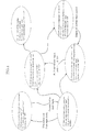
- FIG. 2 is a view schematically illustrating a circuit configuration of a secondary battery pack system according to the embodiment of the present invention.
- FIG. 2 illustrates a secondary battery pack system including two battery packs which are connected in parallel.
- reference numeral 100 denotes a battery pack 1
- 100' denotes a battery pack 2 for the sake of simplification.
- the battery packs 1 and 2 each have the same configuration as the battery pack illustrated in FIG. 1 .
- the discharge control signals from the battery packs 1 and 2 are connected to a main body side discharge control signal line of a main body side connection circuit of the electronic device 200 and are pulled up by a resistor R4.
- the terminal T3 for battery connection signal is connected to GND as illustrated. Further, when the battery pack is connected to the main body side connection circuit, the battery connection signal to be input to the input port is changed from Hi-level to Low level, whereby the controller can recognize that a connection between the battery pack and main body have been established.
- FIGS. 3 (A) to 3 (C) are views each obtained by extracting only the discharge control signal line of the secondary battery pack system according to the embodiment of the present invention.
- FIG. 3(A) illustrates a state where no battery pack discharges its energy
- FIG. 3(B) illustrates a state where one battery pack discharges its energy
- FIG. 3(C) illustrates a state where two battery packs discharge their energy.
- the terminal of the N-ch open drain output port assumes a LOW level, that is, the terminal of the N-ch open drain output port is connected to GND.
- the sum of values of the pull-up resistors is 9.98 k ⁇ , and the value of the pull-down resistor is 10 k ⁇ , so that the voltage of the discharge control signal line is about 2.5 V.
- the pull-down resistors of 10 k ⁇ are arranged in two-parallel configuration, resulting in 5 k ⁇ .
- the sum of values of the pull-up resistors is 9.98 k ⁇ , so that the voltage of the discharge control signal line is about 1.66 V.
- the voltage of the discharge control signal line is decreased, making it easy to grasp whether one or more battery packs discharge their energy or individual battery pack discharges its energy without requiring a complicated system.
- FIG. 4 is a state transition view of the secondary battery pack system according to the embodiment of the present invention.
- the discharge switch SW is turned OFF in consideration of possibility of external short circuit of the battery pack.
- the present invention is designed mainly for a battery pack having a two or more series-connected battery cells (about 8 V). Further, it is possible to use even a battery pack having one series-connected battery cell by changing the detection range of the A/D conversion input port.
- the battery pack constituting the secondary battery pack system has the discharge control signal and battery connection signal.
- a control is made based on the state of these signals so as not to allow a control-target battery pack to perform discharging when any other battery pack than the control-target battery pack is discharging its energy.
- the battery packs discharge their energy in a one-by-one manner.
- the discharge control signal is change from "Low” to "open” to allow the next battery pack to start discharging its energy so as to continue power supply.
- the present invention relates to a secondary battery pack system whose use has recently extended into the field of electrically-powered device or storage.
- a secondary battery pack system whose use has recently extended into the field of electrically-powered device or storage.
- parallel-connected individual battery packs constituting such a secondary battery pack needed to be provided with devices or sensors with which a higher-level controller manages voltage, current, temperature, and the like, causing cost increase.
- a controller is provided for each of a plurality of the battery packs so as to eliminate the above devices or sensors. This contributes to cost reduction and thereby enhance industrial applicability.
Landscapes
- Engineering & Computer Science (AREA)
- Power Engineering (AREA)
- Secondary Cells (AREA)
- Charge And Discharge Circuits For Batteries Or The Like (AREA)
- Battery Mounting, Suspending (AREA)
Abstract
Description
- The present invention relates to a secondary battery pack system for supplying power to an electronic device, etc., and, more particularly, to a secondary battery pack system in which a plurality of battery packs can be connected in parallel.
- A conventional system capable of using secondary battery packs connected in parallel has a configuration in which a diode is used for each battery pack to prevent backflow of electricity for parallel connection or a control signal is issued from a system main body so as to cause each battery pack to discharge its energy.
- For example, PTL 1 (
JP-A-2004-229391
[PTL 1]JP-A-2004-229391 - In the conventional system in which battery packs are connected in parallel and a diode is used for each battery pack to prevent backflow of electricity, power of a battery pack having a higher voltage is first consumed and, finally, all the battery packs connected in parallel are simultaneously over discharged. Then, the battery packs are removed from the system one by one for charging. In this procedure, the time at which charging is to be done is hard to make out.
- Further, in the configuration in which a control signal issued from the system main body is used to control the parallel-connected battery packs, in order to manage the residual capacity of each battery pack, it is necessary to measure the voltage, current, and temperature of each battery pack, to transmit thus obtained measurement information to the system main body, and to determine a battery pack that discharges its energy based on the measurement information. That is, devices or sensors for the above measurements and connector or IC chips for communication, etc., need to be provided, complicating the system configuration, which may result in an increase in cost.
- To solve the above problems, the invention according to
claim 1 is a secondary battery pack system for supplying power to an electronic device, including: a plurality of battery packs each having a controller; a main body side connection circuit which is provided on the electronic device side so as to be connected to the plurality of battery packs; and a main body side discharge control signal line which is provided in the main body side connection circuit. The main body side discharge control signal line and controllers of the plurality of battery packs are connected to each other. - The invention according to
claim 2 is the secondary battery pack system according toclaim 1, wherein, when the battery pack is attached to the electronic device, a discharge control signal line of the controller is connected to the main body side discharge control signal line. - The invention according to
claim 3 is the secondary battery pack system according toclaim 1 orclaim 2, wherein a battery connection signal for recognizing a connection of the battery pack is input to the controller. - The invention according to claim 4 is the secondary battery pack system according to
claim 3, wherein a discharge control signal input from the main body side discharge control signal line is pulled up by a pull-up resistor and is distributed into two lines, and one of the distributed signals is input to the controller via a resistor and the other is directly input to the controller. - The invention according to
claim 5 is the secondary battery pack system according to claim 4, wherein in the main body side connection circuit, the discharge control signal of the battery pack is connected to the main body side discharge control signal line, which is then pulled up by a resistor, and in the main body side connection circuit, the battery connection signal is connected to a GND terminal. - The invention according to claim 6 is the secondary battery pack system according to
claim 5, wherein, when the battery pack is connected to the main body side connection circuit and the level of the battery connection signal is changed, establishment of a connection between the battery pack and main body side connection circuit is recognized, and the voltage of the discharge control signal is read by the controller in the battery pack so as to determine whether discharging is permitted or not. - According to the secondary battery pack system of the embodiment of the present invention, it is possible to control the battery packs which are connected in parallel without necessity of measuring the voltage, current, and temperature of each battery pack, transmitting thus obtained measurement information to the system main body, and determining a battery pack that discharges its energy based on the measurement information. This eliminates the need to provide devices or sensors for the above measurements and connector or IC chips for communication, etc., to simplify the system configuration, leading to a reduction in cost.
-
-
FIG. 1 is a view schematically illustrating a circuit configuration of one battery pack constituting a secondary battery pack system according to an embodiment of the present invention; -
FIG. 2 is a view schematically illustrating a circuit configuration of a secondary battery pack system according to the embodiment of the present invention; -
FIGS. 3(A) to 3(C) are views each obtained by extracting only a discharge control signal line of the secondary battery pack system according to the embodiment of the present invention; and -
FIG. 4 is a state transition view of the secondary battery pack system according to the embodiment of the present invention. - An embodiment of the present invention will be described below with reference to the accompanying drawings.
FIG. 1 is a view schematically illustrating a circuit configuration of one battery pack constituting a secondary battery pack system according to the embodiment of the present invention. - In
FIG. 1 ,reference numeral 100 denotes a battery pack, 110 denotes a controller, CL denotes secondary battery cells, SW denotes a discharge switch, R1, R2, and R3 each denote a resistor, T1, T2, T3, and T4 each denote a connection terminal, and 200 denotes an electronic device. - In this configuration, power charged in the secondary battery cells CL of the
battery pack 100 is supplied to theelectronic device 200 via the discharge switch SW that is tuned ON/OFF by the control of thecontroller 110. Particularly, the present embodiment targets a secondary battery pack system in which a plurality of thebattery packs 100 are connected in parallel. - The
controller 110 constituted using a microcomputer or the like has an N-ch open drain output port, an A/D conversion input port, and an input port. Based on inputs via these ports, thecontroller 110 turns ON/OFF the discharge switch SW to thereby control power supply to theelectronic device 200. - The N-ch open drain output port of the
controller 110 outputs a signal representing the discharge (switch) state of the battery pack. - The A/D conversion input port of the
controller 110 periodically fetches a signal representing the discharge (switch) state of the battery pack. - The input port of the
controller 110 confirms the connection state between the battery pack and a system main body and, in the case where the connection between the battery pack and system main body is not established, turns OFF the discharge switch, and extends the signal fetching period of the A/D conversion input port or stops the operation of the controller. The above function of the input port is useful for reducing power consumed inside the battery pack. - The
battery pack 100 is provided with four connection terminals T1 to T4. Thebattery pack 100 is connected to theelectronic device 200 via the connection terminals T1 to T4. - The connection terminal T1 is a terminal (BATT+) for power supply, connection terminal T2 is a terminal for discharge control signal, connection terminals T3 is a terminal for battery connection signal, and connection terminal T4 is a ground terminal (GND).
- A discharge control signal input via the connection terminal T2 is pulled up by the resistor R2 in the
battery pack 100 and is distributed into two lines for input to thecontroller 110. One of the distributed signals is connected to the N-ch open drain output port via the resistor R1 and the other is directly connected to the AD conversion port. - The discharge control signal of the
battery pack 100 that is discharging its energy makes the N-ch open drain output port into a low state to thereby notify other battery packs of information indicating that discharging is being performed. - The battery connection signal is pulled up by the resistor R3 in the
battery pack 100 and is connected to the input port of thecontroller 110. - Next, a secondary battery pack system in which two
battery packs 100 each having the above configuration are connected in parallel will be described.FIG. 2 is a view schematically illustrating a circuit configuration of a secondary battery pack system according to the embodiment of the present invention.FIG. 2 illustrates a secondary battery pack system including two battery packs which are connected in parallel. InFIG. 2 ,reference numeral 100 denotes abattery pack 1, and 100' denotes abattery pack 2 for the sake of simplification. Thebattery packs FIG. 1 . - The discharge control signals from the
battery packs electronic device 200 and are pulled up by a resistor R4. - When the battery pack is connected to the main body side connection circuit of the
electronic device 200, the terminal T3 for battery connection signal is connected to GND as illustrated. Further, when the battery pack is connected to the main body side connection circuit, the battery connection signal to be input to the input port is changed from Hi-level to Low level, whereby the controller can recognize that a connection between the battery pack and main body have been established. - Next, the discharge control signal line of the secondary battery pack system of
FIG. 2 will be described.FIGS. 3 (A) to 3 (C) are views each obtained by extracting only the discharge control signal line of the secondary battery pack system according to the embodiment of the present invention. - In
FIG. 3 , for more concrete description, the resistance value of each resistor connected to the discharge control signal line is set as follows: R1 = 10 KΩ, R2 = 10 MΩ, and R4 = 10 KΩ. -
FIG. 3(A) illustrates a state where no battery pack discharges its energy,FIG. 3(B) illustrates a state where one battery pack discharges its energy, andFIG. 3(C) illustrates a state where two battery packs discharge their energy. - In the case of
FIG. 3(A) representing a state where no battery pack discharges its energy, the terminal of the N-ch open drain output port is opened, so that the voltage pulled up to 5 V can be directly seen, and thus the voltage of the discharge control signal line is 5V. - In the case of
FIG. 3(B) representing a state where one battery pack discharges its energy, the terminal of the N-ch open drain output port assumes a LOW level, that is, the terminal of the N-ch open drain output port is connected to GND. The sum of values of the pull-up resistors is 9.98 kΩ, and the value of the pull-down resistor is 10 kΩ, so that the voltage of the discharge control signal line is about 2.5 V. - In the case of
FIG. 3(C) representing a state where two battery packs discharge their energy, the pull-down resistors of 10 kΩ are arranged in two-parallel configuration, resulting in 5 kΩ. The sum of values of the pull-up resistors is 9.98 kΩ, so that the voltage of the discharge control signal line is about 1.66 V. - As described above, according to the configuration of the present invention, when the number of battery packs that discharge their energy is increased, the voltage of the discharge control signal line is decreased, making it easy to grasp whether one or more battery packs discharge their energy or individual battery pack discharges its energy without requiring a complicated system.
- Hereinafter, the basic operation of the
controller 110 of the secondary battery pack system according to the embodiment of the present invention will be described.FIG. 4 is a state transition view of the secondary battery pack system according to the embodiment of the present invention. - (1) State where battery pack is not connected
Battery connection signal: Hi-level
Discharge control signal: N-ch open drain output port "open"
Discharge control signal: A/D conversion input port "5V" - Since the battery connection signal assumes a Hi-level, it is determined that the battery pack is in a non-connection state. The discharge switch SW is turned OFF in consideration of possibility of external short circuit of the battery pack.
- (2) State where battery pack is connected to main body side connection circuit
Battery connection signal: Low level
Discharge control signal: N-ch open drain output port "open"
Discharge control signal: A/D conversion input port "3 V to 5V" → Other battery packs do not discharge their energy → Discharge control signal: N-ch open drain output port "LOW" → Discharge switch SW "ON"
Discharge control signal: A/D conversion input port "3 V or less" → Any other battery pack is discharging its energy → Discharge control signal: N-ch open drain output port "open" → Discharge switch SW "OFF" - (3) Last phase of discharging of battery pack
Discharge control signal: N-ch open drain output port "Low" → "open"
Discharge control signal: A/D conversion input port "changing from 3 V or less to 5V" - (4) State where battery pack issues discharge control signal while being connected to main body side connection circuit
In the case where N-ch open drain output port is "open" Discharge control signal: A/D conversion input port "changing to 3V or more"
→ discharge of any other battery pack is ended → discharge switch is turned ON
Discharge control signal: N-ch open drain output port "Low"
Discharge control signal: A/D conversion input port "3 V or less" → Any other battery pack is discharging its energy → Discharge control signal: N-ch open drain output port "open" → Discharge switch SW "OFF" - (5) State where battery pack is discharging its energy
After confirming that any other battery pack is discharging with discharge switch held in ON position for given time, the discharge switch SW is turned OFF.
Discharge control signal: A/D conversion input port "2 V or less" → Any other battery pack is discharging its energy → Discharge control signal: N-ch open drain output port "open" → Discharge switch SW "ON" - The present invention is designed mainly for a battery pack having a two or more series-connected battery cells (about 8 V). Further, it is possible to use even a battery pack having one series-connected battery cell by changing the detection range of the A/D conversion input port.
- As described above, the battery pack constituting the secondary battery pack system according to the embodiment of the present invention has the discharge control signal and battery connection signal. A control is made based on the state of these signals so as not to allow a control-target battery pack to perform discharging when any other battery pack than the control-target battery pack is discharging its energy. As a result, the battery packs discharge their energy in a one-by-one manner. Then, at the last phase of discharging, the discharge control signal is change from "Low" to "open" to allow the next battery pack to start discharging its energy so as to continue power supply. Thus, it is possible to remove only the fully discharged battery pack for charging.
- The present invention relates to a secondary battery pack system whose use has recently extended into the field of electrically-powered device or storage. Conventionally, parallel-connected individual battery packs constituting such a secondary battery pack needed to be provided with devices or sensors with which a higher-level controller manages voltage, current, temperature, and the like, causing cost increase. On the other hand, in the secondary battery pack system, a controller is provided for each of a plurality of the battery packs so as to eliminate the above devices or sensors. This contributes to cost reduction and thereby enhance industrial applicability.
-
- 100:
- Battery pack
- 110:
- Controller
- 200:
- Electronic device
- CL:
- Secondary battery cell
- SW:
- Discharge switch
- R1, R2, R3:
- Resistor
- T1, T2, T3, T4:
- Connection terminal
Claims (6)
- A secondary battery pack system for supplying power to an electronic device, comprising:a plurality of battery packs each having a controller;a main body side connection circuit which is provided on the electronic device side so as to be connected to the plurality of battery packs; anda main body side discharge control signal line which is provided in the main body side connection circuit, whereinthe main body side discharge control signal line and controllers of the plurality of battery packs are connected to each other.
- The secondary battery pack system according to claim 1, wherein,
when the battery pack is attached to the electronic device, a discharge control signal line of the controller is connected to the main body side discharge control signal line. - The secondary battery pack system according to claim 1 or 2, wherein
a battery connection signal for recognizing a connection of the battery pack is input to the controller. - The secondary battery pack system according to claim 3, wherein
a discharge control signal input from the main body side discharge control signal line is pulled up by a pull-up resistor and is distributed into two lines, and one of the distributed signals is input to the controller via a resistor and the other is directly input to the controller. - The secondary battery pack system according to claim 4, wherein,
in the main body side connection circuit, the discharge control signal of the battery pack is connected to the main body side discharge control signal line, which is then pulled up by a resistor, and
in the main body side connection circuit, the battery connection signal is connected to a GND terminal. - The secondary battery pack system according to claim 5, wherein,
when the battery pack is connected to the main body side connection circuit and the level of the battery connection signal is changed, establishment of a connection between the battery pack and main body side connection circuit is recognized, and the voltage of the discharge control signal is read by the controller in the battery pack so as to determine whether discharging is permitted or not.
Applications Claiming Priority (1)
| Application Number | Priority Date | Filing Date | Title |
|---|---|---|---|
| PCT/JP2009/004625 WO2011033558A1 (en) | 2009-09-16 | 2009-09-16 | Secondary battery pack system |
Publications (3)
| Publication Number | Publication Date |
|---|---|
| EP2479864A1 true EP2479864A1 (en) | 2012-07-25 |
| EP2479864A4 EP2479864A4 (en) | 2013-12-25 |
| EP2479864B1 EP2479864B1 (en) | 2016-04-20 |
Family
ID=43758187
Family Applications (1)
| Application Number | Title | Priority Date | Filing Date |
|---|---|---|---|
| EP09849418.0A Not-in-force EP2479864B1 (en) | 2009-09-16 | 2009-09-16 | Secondary battery pack system |
Country Status (4)
| Country | Link |
|---|---|
| US (2) | US8803483B2 (en) |
| EP (1) | EP2479864B1 (en) |
| CN (1) | CN102484375B (en) |
| WO (1) | WO2011033558A1 (en) |
Families Citing this family (5)
| Publication number | Priority date | Publication date | Assignee | Title |
|---|---|---|---|---|
| US9673738B2 (en) | 2014-05-16 | 2017-06-06 | Techtronic Power Tools Technology Limited | Multi-battery pack for power tools |
| EP3905479B1 (en) * | 2016-11-14 | 2025-05-07 | SZ DJI Technology Co., Ltd. | Multi-battery system and management thereof |
| CN110768361B (en) * | 2019-11-19 | 2024-02-02 | 格力博(江苏)股份有限公司 | electrical tools |
| US11691261B2 (en) * | 2020-06-02 | 2023-07-04 | Snap-On Incorporated | Housing clamp for a power tool |
| HUE062680T2 (en) * | 2020-12-16 | 2023-12-28 | Contemporary Amperex Technology Co Ltd | Power supply apparatus, battery management system, power supply system, control method and medium |
Family Cites Families (17)
| Publication number | Priority date | Publication date | Assignee | Title |
|---|---|---|---|---|
| JP2928431B2 (en) * | 1993-01-13 | 1999-08-03 | 富士通株式会社 | Auxiliary battery device and charge / discharge control method |
| JP3223659B2 (en) | 1993-09-13 | 2001-10-29 | オムロン株式会社 | Uninterruptible power system |
| JPH10124182A (en) * | 1996-10-24 | 1998-05-15 | Fujitsu Ltd | Portable computer device to which an additional battery can be attached |
| US6043626A (en) * | 1996-10-29 | 2000-03-28 | Ericsson Inc. | Auxiliary battery holder with multicharger functionality |
| US6184654B1 (en) * | 1998-07-28 | 2001-02-06 | Double-Time Battery Corporation | Wearable docking-holster system, with energy management, to support portable electronic devices |
| JP2000116014A (en) | 1998-10-06 | 2000-04-21 | Hitachi Ltd | Power storage device |
| JP2001057247A (en) * | 1999-08-17 | 2001-02-27 | Hitachi Maxell Ltd | Rechargeable battery or rechargeable battery pack |
| JP3655171B2 (en) | 2000-06-22 | 2005-06-02 | 富士通株式会社 | Charge / discharge control circuit and secondary battery device |
| US7145312B2 (en) * | 2002-12-06 | 2006-12-05 | Comarco Wireless Technologies, Inc. | Battery coupled to adapter and tip |
| JP2004229391A (en) | 2003-01-22 | 2004-08-12 | Sony Corp | Battery pack |
| JP4101205B2 (en) * | 2004-05-11 | 2008-06-18 | 松下電器産業株式会社 | Battery pack and power supply |
| US7453236B2 (en) | 2005-10-21 | 2008-11-18 | Lg Chem, Ltd. | Battery pack of automatically setting master and slave pack, multi-battery pack system including the same and method for controlling the same |
| US7688029B2 (en) * | 2005-11-08 | 2010-03-30 | Eveready Battery Company, Inc. | Portable battery powered appliance and method of operation |
| JP4886530B2 (en) * | 2007-01-24 | 2012-02-29 | パナソニック株式会社 | Electronic device system and battery pack |
| JP5127383B2 (en) * | 2007-09-28 | 2013-01-23 | 株式会社日立製作所 | Battery integrated circuit and vehicle power supply system using the battery integrated circuit |
| JP4692554B2 (en) | 2008-02-06 | 2011-06-01 | ソニー株式会社 | Charger |
| JP5267975B2 (en) * | 2008-03-28 | 2013-08-21 | Necエナジーデバイス株式会社 | Secondary battery pack system |
-
2009
- 2009-09-16 US US13/318,641 patent/US8803483B2/en active Active
- 2009-09-16 EP EP09849418.0A patent/EP2479864B1/en not_active Not-in-force
- 2009-09-16 WO PCT/JP2009/004625 patent/WO2011033558A1/en not_active Ceased
- 2009-09-16 CN CN200980161465.2A patent/CN102484375B/en not_active Expired - Fee Related
-
2014
- 2014-03-10 US US14/202,442 patent/US9118200B2/en active Active
Also Published As
| Publication number | Publication date |
|---|---|
| US20120056597A1 (en) | 2012-03-08 |
| CN102484375B (en) | 2014-12-03 |
| US8803483B2 (en) | 2014-08-12 |
| US9118200B2 (en) | 2015-08-25 |
| EP2479864A4 (en) | 2013-12-25 |
| EP2479864B1 (en) | 2016-04-20 |
| CN102484375A (en) | 2012-05-30 |
| US20140184167A1 (en) | 2014-07-03 |
| WO2011033558A1 (en) | 2011-03-24 |
Similar Documents
| Publication | Publication Date | Title |
|---|---|---|
| EP2706646B1 (en) | Cell balancing system | |
| EP1806592B1 (en) | Method and system for monitoring battery stacks | |
| US9118200B2 (en) | Secondary battery pack system | |
| US8793087B2 (en) | Modular device for protecting and monitoring a battery | |
| CN102165626B (en) | Multiple series/multiple parallel battery pack | |
| CN107147153A (en) | Battery management system and battery system using it | |
| EP0988684A1 (en) | Multi-functional battery management module operable in a charging mode and a battery pack mode | |
| US9236753B2 (en) | Power source device and method of controlling assembled battery | |
| EP1977263B1 (en) | Device for monitoring cell voltage | |
| KR102045047B1 (en) | Maximum capacity charging apparatus considering SOH unbalance of battery module and control method thereof | |
| JP2011097772A (en) | Battery-state monitoring circuit and battery device | |
| US20060091854A1 (en) | Power monitoring and balancing device | |
| US9281698B2 (en) | Battery pack | |
| CN101325342A (en) | Charger for storage battery | |
| US8294423B2 (en) | Voltage measuring device | |
| JP2003282159A (en) | Battery control system | |
| EP2216873A2 (en) | Battery state monitoring circuit and battery device | |
| KR100942640B1 (en) | Lithium polymer battery alarm method for radio control | |
| US20150185291A1 (en) | Switched capacitor battery unit monitoring system | |
| US8487588B2 (en) | Battery pack | |
| CN101144837A (en) | Voltage detection circuit and method thereof | |
| JP5267975B2 (en) | Secondary battery pack system | |
| CN109075603A (en) | Determine the capacity of the accumulator of the DC power supply unit without interruption | |
| TWI392188B (en) | 2 times battery pack system | |
| JP2014236584A (en) | Battery pack |
Legal Events
| Date | Code | Title | Description |
|---|---|---|---|
| PUAI | Public reference made under article 153(3) epc to a published international application that has entered the european phase |
Free format text: ORIGINAL CODE: 0009012 |
|
| 17P | Request for examination filed |
Effective date: 20111206 |
|
| AK | Designated contracting states |
Kind code of ref document: A1 Designated state(s): AT BE BG CH CY CZ DE DK EE ES FI FR GB GR HR HU IE IS IT LI LT LU LV MC MK MT NL NO PL PT RO SE SI SK SM TR |
|
| DAX | Request for extension of the european patent (deleted) | ||
| A4 | Supplementary search report drawn up and despatched |
Effective date: 20131127 |
|
| RIC1 | Information provided on ipc code assigned before grant |
Ipc: H02J 7/00 20060101AFI20131121BHEP |
|
| GRAP | Despatch of communication of intention to grant a patent |
Free format text: ORIGINAL CODE: EPIDOSNIGR1 |
|
| INTG | Intention to grant announced |
Effective date: 20150724 |
|
| RIN1 | Information on inventor provided before grant (corrected) |
Inventor name: NAGASE, KAZUHISA |
|
| GRAS | Grant fee paid |
Free format text: ORIGINAL CODE: EPIDOSNIGR3 |
|
| INTG | Intention to grant announced |
Effective date: 20160104 |
|
| GRAA | (expected) grant |
Free format text: ORIGINAL CODE: 0009210 |
|
| AK | Designated contracting states |
Kind code of ref document: B1 Designated state(s): AT BE BG CH CY CZ DE DK EE ES FI FR GB GR HR HU IE IS IT LI LT LU LV MC MK MT NL NO PL PT RO SE SI SK SM TR |
|
| REG | Reference to a national code |
Ref country code: GB Ref legal event code: FG4D |
|
| REG | Reference to a national code |
Ref country code: CH Ref legal event code: EP |
|
| REG | Reference to a national code |
Ref country code: AT Ref legal event code: REF Ref document number: 793388 Country of ref document: AT Kind code of ref document: T Effective date: 20160515 |
|
| REG | Reference to a national code |
Ref country code: IE Ref legal event code: FG4D |
|
| REG | Reference to a national code |
Ref country code: DE Ref legal event code: R096 Ref document number: 602009038129 Country of ref document: DE |
|
| REG | Reference to a national code |
Ref country code: LT Ref legal event code: MG4D |
|
| REG | Reference to a national code |
Ref country code: AT Ref legal event code: MK05 Ref document number: 793388 Country of ref document: AT Kind code of ref document: T Effective date: 20160420 |
|
| REG | Reference to a national code |
Ref country code: NL Ref legal event code: MP Effective date: 20160420 Ref country code: FR Ref legal event code: PLFP Year of fee payment: 8 |
|
| PG25 | Lapsed in a contracting state [announced via postgrant information from national office to epo] |
Ref country code: FI Free format text: LAPSE BECAUSE OF FAILURE TO SUBMIT A TRANSLATION OF THE DESCRIPTION OR TO PAY THE FEE WITHIN THE PRESCRIBED TIME-LIMIT Effective date: 20160420 Ref country code: LT Free format text: LAPSE BECAUSE OF FAILURE TO SUBMIT A TRANSLATION OF THE DESCRIPTION OR TO PAY THE FEE WITHIN THE PRESCRIBED TIME-LIMIT Effective date: 20160420 Ref country code: NL Free format text: LAPSE BECAUSE OF FAILURE TO SUBMIT A TRANSLATION OF THE DESCRIPTION OR TO PAY THE FEE WITHIN THE PRESCRIBED TIME-LIMIT Effective date: 20160420 Ref country code: NO Free format text: LAPSE BECAUSE OF FAILURE TO SUBMIT A TRANSLATION OF THE DESCRIPTION OR TO PAY THE FEE WITHIN THE PRESCRIBED TIME-LIMIT Effective date: 20160720 Ref country code: PL Free format text: LAPSE BECAUSE OF FAILURE TO SUBMIT A TRANSLATION OF THE DESCRIPTION OR TO PAY THE FEE WITHIN THE PRESCRIBED TIME-LIMIT Effective date: 20160420 |
|
| PG25 | Lapsed in a contracting state [announced via postgrant information from national office to epo] |
Ref country code: AT Free format text: LAPSE BECAUSE OF FAILURE TO SUBMIT A TRANSLATION OF THE DESCRIPTION OR TO PAY THE FEE WITHIN THE PRESCRIBED TIME-LIMIT Effective date: 20160420 Ref country code: ES Free format text: LAPSE BECAUSE OF FAILURE TO SUBMIT A TRANSLATION OF THE DESCRIPTION OR TO PAY THE FEE WITHIN THE PRESCRIBED TIME-LIMIT Effective date: 20160420 Ref country code: SE Free format text: LAPSE BECAUSE OF FAILURE TO SUBMIT A TRANSLATION OF THE DESCRIPTION OR TO PAY THE FEE WITHIN THE PRESCRIBED TIME-LIMIT Effective date: 20160420 Ref country code: LV Free format text: LAPSE BECAUSE OF FAILURE TO SUBMIT A TRANSLATION OF THE DESCRIPTION OR TO PAY THE FEE WITHIN THE PRESCRIBED TIME-LIMIT Effective date: 20160420 Ref country code: GR Free format text: LAPSE BECAUSE OF FAILURE TO SUBMIT A TRANSLATION OF THE DESCRIPTION OR TO PAY THE FEE WITHIN THE PRESCRIBED TIME-LIMIT Effective date: 20160721 Ref country code: HR Free format text: LAPSE BECAUSE OF FAILURE TO SUBMIT A TRANSLATION OF THE DESCRIPTION OR TO PAY THE FEE WITHIN THE PRESCRIBED TIME-LIMIT Effective date: 20160420 Ref country code: PT Free format text: LAPSE BECAUSE OF FAILURE TO SUBMIT A TRANSLATION OF THE DESCRIPTION OR TO PAY THE FEE WITHIN THE PRESCRIBED TIME-LIMIT Effective date: 20160822 |
|
| PG25 | Lapsed in a contracting state [announced via postgrant information from national office to epo] |
Ref country code: BE Free format text: LAPSE BECAUSE OF FAILURE TO SUBMIT A TRANSLATION OF THE DESCRIPTION OR TO PAY THE FEE WITHIN THE PRESCRIBED TIME-LIMIT Effective date: 20160420 Ref country code: IT Free format text: LAPSE BECAUSE OF FAILURE TO SUBMIT A TRANSLATION OF THE DESCRIPTION OR TO PAY THE FEE WITHIN THE PRESCRIBED TIME-LIMIT Effective date: 20160420 |
|
| REG | Reference to a national code |
Ref country code: DE Ref legal event code: R097 Ref document number: 602009038129 Country of ref document: DE |
|
| PG25 | Lapsed in a contracting state [announced via postgrant information from national office to epo] |
Ref country code: CZ Free format text: LAPSE BECAUSE OF FAILURE TO SUBMIT A TRANSLATION OF THE DESCRIPTION OR TO PAY THE FEE WITHIN THE PRESCRIBED TIME-LIMIT Effective date: 20160420 Ref country code: EE Free format text: LAPSE BECAUSE OF FAILURE TO SUBMIT A TRANSLATION OF THE DESCRIPTION OR TO PAY THE FEE WITHIN THE PRESCRIBED TIME-LIMIT Effective date: 20160420 Ref country code: DK Free format text: LAPSE BECAUSE OF FAILURE TO SUBMIT A TRANSLATION OF THE DESCRIPTION OR TO PAY THE FEE WITHIN THE PRESCRIBED TIME-LIMIT Effective date: 20160420 Ref country code: SK Free format text: LAPSE BECAUSE OF FAILURE TO SUBMIT A TRANSLATION OF THE DESCRIPTION OR TO PAY THE FEE WITHIN THE PRESCRIBED TIME-LIMIT Effective date: 20160420 Ref country code: RO Free format text: LAPSE BECAUSE OF FAILURE TO SUBMIT A TRANSLATION OF THE DESCRIPTION OR TO PAY THE FEE WITHIN THE PRESCRIBED TIME-LIMIT Effective date: 20160420 |
|
| PLBE | No opposition filed within time limit |
Free format text: ORIGINAL CODE: 0009261 |
|
| STAA | Information on the status of an ep patent application or granted ep patent |
Free format text: STATUS: NO OPPOSITION FILED WITHIN TIME LIMIT |
|
| PG25 | Lapsed in a contracting state [announced via postgrant information from national office to epo] |
Ref country code: SM Free format text: LAPSE BECAUSE OF FAILURE TO SUBMIT A TRANSLATION OF THE DESCRIPTION OR TO PAY THE FEE WITHIN THE PRESCRIBED TIME-LIMIT Effective date: 20160420 |
|
| 26N | No opposition filed |
Effective date: 20170123 |
|
| PG25 | Lapsed in a contracting state [announced via postgrant information from national office to epo] |
Ref country code: MC Free format text: LAPSE BECAUSE OF FAILURE TO SUBMIT A TRANSLATION OF THE DESCRIPTION OR TO PAY THE FEE WITHIN THE PRESCRIBED TIME-LIMIT Effective date: 20160420 |
|
| REG | Reference to a national code |
Ref country code: CH Ref legal event code: PL |
|
| PG25 | Lapsed in a contracting state [announced via postgrant information from national office to epo] |
Ref country code: SI Free format text: LAPSE BECAUSE OF FAILURE TO SUBMIT A TRANSLATION OF THE DESCRIPTION OR TO PAY THE FEE WITHIN THE PRESCRIBED TIME-LIMIT Effective date: 20160420 |
|
| REG | Reference to a national code |
Ref country code: IE Ref legal event code: MM4A |
|
| PG25 | Lapsed in a contracting state [announced via postgrant information from national office to epo] |
Ref country code: CH Free format text: LAPSE BECAUSE OF NON-PAYMENT OF DUE FEES Effective date: 20160930 Ref country code: IE Free format text: LAPSE BECAUSE OF NON-PAYMENT OF DUE FEES Effective date: 20160916 Ref country code: LI Free format text: LAPSE BECAUSE OF NON-PAYMENT OF DUE FEES Effective date: 20160930 |
|
| REG | Reference to a national code |
Ref country code: FR Ref legal event code: PLFP Year of fee payment: 9 |
|
| PG25 | Lapsed in a contracting state [announced via postgrant information from national office to epo] |
Ref country code: LU Free format text: LAPSE BECAUSE OF NON-PAYMENT OF DUE FEES Effective date: 20160916 |
|
| PG25 | Lapsed in a contracting state [announced via postgrant information from national office to epo] |
Ref country code: HU Free format text: LAPSE BECAUSE OF FAILURE TO SUBMIT A TRANSLATION OF THE DESCRIPTION OR TO PAY THE FEE WITHIN THE PRESCRIBED TIME-LIMIT; INVALID AB INITIO Effective date: 20090916 Ref country code: CY Free format text: LAPSE BECAUSE OF FAILURE TO SUBMIT A TRANSLATION OF THE DESCRIPTION OR TO PAY THE FEE WITHIN THE PRESCRIBED TIME-LIMIT Effective date: 20160420 |
|
| PG25 | Lapsed in a contracting state [announced via postgrant information from national office to epo] |
Ref country code: MT Free format text: LAPSE BECAUSE OF NON-PAYMENT OF DUE FEES Effective date: 20160930 Ref country code: IS Free format text: LAPSE BECAUSE OF FAILURE TO SUBMIT A TRANSLATION OF THE DESCRIPTION OR TO PAY THE FEE WITHIN THE PRESCRIBED TIME-LIMIT Effective date: 20160420 Ref country code: MK Free format text: LAPSE BECAUSE OF FAILURE TO SUBMIT A TRANSLATION OF THE DESCRIPTION OR TO PAY THE FEE WITHIN THE PRESCRIBED TIME-LIMIT Effective date: 20160420 Ref country code: TR Free format text: LAPSE BECAUSE OF FAILURE TO SUBMIT A TRANSLATION OF THE DESCRIPTION OR TO PAY THE FEE WITHIN THE PRESCRIBED TIME-LIMIT Effective date: 20160420 |
|
| PG25 | Lapsed in a contracting state [announced via postgrant information from national office to epo] |
Ref country code: BG Free format text: LAPSE BECAUSE OF FAILURE TO SUBMIT A TRANSLATION OF THE DESCRIPTION OR TO PAY THE FEE WITHIN THE PRESCRIBED TIME-LIMIT Effective date: 20160420 |
|
| REG | Reference to a national code |
Ref country code: FR Ref legal event code: PLFP Year of fee payment: 10 |
|
| REG | Reference to a national code |
Ref country code: GB Ref legal event code: 732E Free format text: REGISTERED BETWEEN 20190704 AND 20190710 |
|
| REG | Reference to a national code |
Ref country code: DE Ref legal event code: R082 Ref document number: 602009038129 Country of ref document: DE Representative=s name: HOYNG ROKH MONEGIER PARTNERSCHAFTSGESELLSCHAFT, DE Ref country code: DE Ref legal event code: R081 Ref document number: 602009038129 Country of ref document: DE Owner name: ENVISION AESC ENERGY DEVICES LTD., SAGAMIHARA-, JP Free format text: FORMER OWNER: NEC ENERGY DEVICES, LTD., SAGAMIHARA-SHI, KANAGAWA, JP Ref country code: DE Ref legal event code: R082 Ref document number: 602009038129 Country of ref document: DE Representative=s name: VOSSIUS & PARTNER PATENTANWAELTE RECHTSANWAELT, DE |
|
| REG | Reference to a national code |
Ref country code: DE Ref legal event code: R082 Ref document number: 602009038129 Country of ref document: DE Representative=s name: VOSSIUS & PARTNER PATENTANWAELTE RECHTSANWAELT, DE |
|
| P01 | Opt-out of the competence of the unified patent court (upc) registered |
Effective date: 20230428 |
|
| PGFP | Annual fee paid to national office [announced via postgrant information from national office to epo] |
Ref country code: GB Payment date: 20230727 Year of fee payment: 15 |
|
| PGFP | Annual fee paid to national office [announced via postgrant information from national office to epo] |
Ref country code: FR Payment date: 20230808 Year of fee payment: 15 Ref country code: DE Payment date: 20230802 Year of fee payment: 15 |
|
| REG | Reference to a national code |
Ref country code: GB Ref legal event code: 732E Free format text: REGISTERED BETWEEN 20240516 AND 20240522 |
|
| REG | Reference to a national code |
Ref country code: DE Ref legal event code: R119 Ref document number: 602009038129 Country of ref document: DE |
|
| GBPC | Gb: european patent ceased through non-payment of renewal fee |
Effective date: 20240916 |
|
| PG25 | Lapsed in a contracting state [announced via postgrant information from national office to epo] |
Ref country code: DE Free format text: LAPSE BECAUSE OF NON-PAYMENT OF DUE FEES Effective date: 20250401 |
|
| PG25 | Lapsed in a contracting state [announced via postgrant information from national office to epo] |
Ref country code: GB Free format text: LAPSE BECAUSE OF NON-PAYMENT OF DUE FEES Effective date: 20240916 |
|
| PG25 | Lapsed in a contracting state [announced via postgrant information from national office to epo] |
Ref country code: FR Free format text: LAPSE BECAUSE OF NON-PAYMENT OF DUE FEES Effective date: 20240930 |