EP2479799A1 - Solar cell module laminate - Google Patents
Solar cell module laminate Download PDFInfo
- Publication number
- EP2479799A1 EP2479799A1 EP10816941A EP10816941A EP2479799A1 EP 2479799 A1 EP2479799 A1 EP 2479799A1 EP 10816941 A EP10816941 A EP 10816941A EP 10816941 A EP10816941 A EP 10816941A EP 2479799 A1 EP2479799 A1 EP 2479799A1
- Authority
- EP
- European Patent Office
- Prior art keywords
- solar cell
- cell module
- adhesive
- laminated body
- adhesive layer
- Prior art date
- Legal status (The legal status is an assumption and is not a legal conclusion. Google has not performed a legal analysis and makes no representation as to the accuracy of the status listed.)
- Withdrawn
Links
Images


Classifications
-
- H—ELECTRICITY
- H10—SEMICONDUCTOR DEVICES; ELECTRIC SOLID-STATE DEVICES NOT OTHERWISE PROVIDED FOR
- H10F—INORGANIC SEMICONDUCTOR DEVICES SENSITIVE TO INFRARED RADIATION, LIGHT, ELECTROMAGNETIC RADIATION OF SHORTER WAVELENGTH OR CORPUSCULAR RADIATION
- H10F19/00—Integrated devices, or assemblies of multiple devices, comprising at least one photovoltaic cell covered by group H10F10/00, e.g. photovoltaic modules
- H10F19/80—Encapsulations or containers for integrated devices, or assemblies of multiple devices, having photovoltaic cells
-
- Y—GENERAL TAGGING OF NEW TECHNOLOGICAL DEVELOPMENTS; GENERAL TAGGING OF CROSS-SECTIONAL TECHNOLOGIES SPANNING OVER SEVERAL SECTIONS OF THE IPC; TECHNICAL SUBJECTS COVERED BY FORMER USPC CROSS-REFERENCE ART COLLECTIONS [XRACs] AND DIGESTS
- Y02—TECHNOLOGIES OR APPLICATIONS FOR MITIGATION OR ADAPTATION AGAINST CLIMATE CHANGE
- Y02E—REDUCTION OF GREENHOUSE GAS [GHG] EMISSIONS, RELATED TO ENERGY GENERATION, TRANSMISSION OR DISTRIBUTION
- Y02E10/00—Energy generation through renewable energy sources
- Y02E10/50—Photovoltaic [PV] energy
Definitions
- the present invention relates to a solar cell module laminated body including a solar cell module and a supporting body, such as a metal plate, resin sheet, or tile, that supports the solar cell module, and relates to a solar cell module laminated body wherein the solar cell module is bonded to the supporting body using an adhesive layer.
- Patent Document 1 there is disclosed a laminated body wherein a solar cell panel and at least thermal insulating material and a flat plate, provided on the rear surface side of the solar cell panel, are integrated using an adhesive layer.
- Patent Document 2 there is disclosed a configuration wherein a metal roof and a solar cell panel are bonded using double-sided tape.
- the invention having been contrived in order to solve these kinds of problem, has an object of providing a solar cell module laminated body with a structure wherein it is possible to balance a reduction in the cost of the solar cell module laminated body and sufficient adhesive strength of a supporting body and solar cell module.
- the invention is a solar cell module laminated body including a solar cell module and a supporting body formed by a metal plate, resin sheet, tile, or the like, that supports the solar cell module, the solar cell module being bonded to the supporting body using an adhesive layer, wherein an adhesive area proportional to adhesive strength is determined based on the strength ratio of a shear adhesive strength required of the solar cell module laminated body and a tensile shear adhesive strength when assuming that the whole area of the solar cell module is bonded.
- an adhesive area proportional to adhesive strength is determined based on the strength ratio of a shear adhesive strength required of the solar cell module laminated body and a tensile shear adhesive strength when assuming that the whole area of the solar cell module is bonded.
- the cost decreases in accordance with the amount of adhesive layer, and it is possible to obtain a solar cell module laminated body with a structure wherein it is possible to balance a reduction in the cost of the solar cell module laminated body and sufficient adhesive strength between a supporting body and solar cell module.
- Fig. 1 is a sectional view showing the structure of a solar cell module laminated body according to the embodiment of the invention.
- the solar cell module laminated body is configured by a solar cell module 1 being supported by a supporting body 2 across an adhesive layer 3.
- a solar cell element 4 is enveloped by the solar cell module 1.
- the adhesive layer 3 occupies one portion between the solar cell module 1 and supporting body 2.
- the portion between the solar cell module 1 and supporting body 2 not occupied by the adhesive layer 3 is an empty space, but a material other than the adhesive layer, for example, a drying agent or a heat transfer agent, may be packed into one portion or the whole of the empty space.
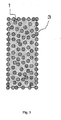
- the form of the adhesive layer 3 interposed between the solar cell module 1 and supporting body 2 is not particularly limited, a band form and circular form are suggested as preferable examples. Of these, a plane sectional view when the adhesive layer is an assembly of band-like portions is shown in Fig. 2 . Also, a plane sectional view when the adhesive layer is an assembly of circular portions is shown in Fig. 3 .
- an advantage of preventing detachment of the solar cell module 1 from the supporting body 2 is particularly high.
- a polymeric material such as polyethylene, an ethylene-vinyl acetate copolymer, a fluorine series resin, or a polyester resin, or a metal, can be used as the material of an adhesive surface side of the solar cell module 1.
- a metal plate, a resin sheet, a tile, or the like, can be used for the supporting body 2. These may be such that the surface is covered with a material other than the main material thereof.
- the solar cell module laminated body obtained in the invention is also flexible, meaning that there is an advantage in that there is an increase in ways of using the solar cell module laminated body, such as installing it on a curved surface portion of an external wall of a building or transporting it rolled up.
- the elasticity of the adhesive layer 3 is 100 MPa or less, and in order to maintain adhesive strength, thus preventing unnecessary distortion of the solar cell module laminated body, it is preferable that the elasticity of the adhesive layer 3 is 100 kPa or more.
- a reaction curing type adhesive or a pressure sensitive adhesive sheet can be used for the adhesive layer 3.
- a silicone series adhesive an acrylic adhesive, an epoxy series adhesive, or the like
- a silicone series adhesive is particularly suitable.
- a moisture curing type, a thermal curing type, a light curing type, or a two-liquid mixed curing type of adhesive is possible.
- a butyl rubber series, acrylic foam series, or the like is possible to use one of a pressure sensitive adhesive sheet, and it may also contain a film, a mesh, or the like, with an object of increasing strength, or the like.
- An adhesive area of the adhesive layer 3 disposed between the solar cell module 1 and supporting body 2 is calculated using the following Equation (1).
- Aa Am ⁇ Sd / Sm
- Am is the area of the solar cell module 1
- Sd is the value of the minimum shear strength of the solar cell module 1 and supporting body 2 required of the solar cell module laminated body
- Sm is the value of the shear adhesive strength exerted over the whole of the solar cell module 1 and supporting body 2 when supposing an adhesion over the whole surface of the solar cell module 1 using the adhesive layer 3.
- the tensile shear adhesive strength of the solar cell module 1 and supporting body 2 of the solar cell module laminated body obtained by adhesion with the adhesive layer 3 having the adhesive area Aa calculated using Equation (1) is the tensile shear adhesive strength Sd. Also, in the case of this adhesive area, the amount of the adhesive layer is minimal, and the solar cell module laminated body cost reducing effect is high.
- the adhesive area of the adhesive layer 3 may be larger than the previously mentioned Aa calculated using Equation (1).
- the adhesive layer 3 with an adhesive area larger than the previously mentioned Aa it is possible to obtain a solar cell module laminated body with a tensile shear adhesive strength greater than the previously mentioned Sd.
- a flexible type with a thickness of 0.85 mm is used for the solar cell module.
- the material of the adhesive surface side is an ethylene tetrafluoroethylene copolymer, and the surface of the adhesive surface side is plasma treated.
- a polyvinylidene fluoride-chlorine trifluoride vinyl copolymer sheet with a thickness of 0.58 mm is used for the supporting body.
- a tape-form acrylic foam series pressure sensitive adhesive sheet with a thickness of 0.4 mm and width of 12.5 mm is used for the adhesive.
- the solar cell module in Example 1 has a length of 500 mm and a width of 250 mm, meaning that the area Am of the solar cell module used in Equation (1) is 125,000 mm 2 .
- the shear adhesive strength Sd required of the solar cell module laminated body in Example 1, being a value set based on the installation environment and the like, is 3.0 N/cm 2 .
- the shear adhesive strength Sm of the tape-form acrylic foam series pressure sensitive adhesive sheet in Example 1 is calculated by bonding the solar cell module and supporting body over an adhesive area of 1 cm 2 using the tape-form acrylic foam series pressure sensitive adhesive sheet and conducting a shear adhesive strength test, the result of which is 24. 0 N/cm 2 . Also, the price of the tape-form acrylic foam series pressure sensitive adhesive sheet is 0.4 yen per 1 cm 2 .
- Equation (1) the necessary adhesive area Aa is calculated to be 15,625 mm 2 . Therefore, a solar cell module laminated body is obtained by making the adhesive area 18,750 mm 2 using three of the tape-form acrylic foam series pressure sensitive adhesive sheets with a length of 500 mm, and bonding the solar cell module and supporting body in the way shown in Fig. 2 .
- the price of the tape-form acrylic foam series pressure sensitive adhesive sheet used is calculated from the unit price thereof and the adhesive area to be 75 yen. Also, the result of measuring the shear adhesive strength of the solar cell module laminated body obtained is 3.5 N/cm 2 , exceeding the required value of 3.0 N/cm 2 .
- a solar cell module laminated body is obtained by making the adhesive area 12,500 mm 2 using two tape-form acrylic foam series pressure sensitive adhesive sheets with a length of 500 mm, and bonding in the same way as that shown in Fig. 2 .
- the price of the tape-form acrylic foam series pressure sensitive adhesive sheet used is calculated from the unit price thereof and the adhesive area to be 50 yen, lower than the 75 yen of Example 1.
- the shear adhesive strength of the solar cell module laminated body obtained is 2.3 N/cm 2 , lower than the required value of 3.0 N/cm 2 , it is clear that it does not stand up to use.
- a solar cell module laminated body is obtained by making the adhesive area 125, 000 mm 2 using twenty tape-form acrylic foam series pressure sensitive adhesive sheets with a length of 500 mm, and bonding over the whole surface of the solar cell module.
- the result of measuring the shear adhesive strength of the solar cell module laminated body obtained is 23.1 N/cm 2 , exceeding the required value of 3.0 N/cm 2 .
- the price of the tape-form acrylic foam series pressure sensitive adhesive sheet used is calculated from the unit price thereof and the adhesive area to be 500 yen, exceeding the 75 yen of Example 1.
- Example 2 The same solar cell module and supporting body as in Example 1 are used.
- a moisture curing type silicone series adhesive is used for the adhesive layer, and the coating thickness is 0.5 mm.
- the shear adhesive strength Sd required of the solar cell module laminated body in Example 2 being a value set based on the installation environment and the like, is 2.0 N/cm 2 .
- the shear adhesive strength Sm of the moisture curing type silicone series adhesive in Example 2 is calculated by bonding the solar cell module and supporting body over an adhesive area of 1 cm 2 using the moisture curing type silicone series adhesive and conducting a shear adhesive strength test, the result of which is 22.4 N/cm 2 . Also, the price when applying the moisture curing type silicone series adhesive to a thickness of 0.5 mm is 0.45 yen per 1 cm 2 .
- Equation (1) the necessary adhesive area Aa is calculated to be 11,161 mm 2 . Therefore, a solar cell module laminated body is obtained by making the adhesive area 12, 000 mm 2 , and bonding the solar cell module and supporting body in the way shown in Fig. 3 .
- the price of the moisture curing type silicone series adhesive used is calculated from the unit price thereof and the adhesive area to be 54 yen. Also, the result of measuring the shear adhesive strength of the solar cell module laminated body obtained is 2.1 N/cm 2 , exceeding the required value of 2.0 N/cm 2 .
- the amount of moisture curing type silicone series adhesive used is changed with respect to the conditions of Example 2, and a solar cell module laminated body is obtained by making the adhesive area 10, 000 cm 2 , and bonding in the same way as that shown in Fig. 3 .
- the price of the moisture curing type silicone series adhesive used is calculated from the unit price thereof and the adhesive area to be 45 yen, lower than the 54 yen of Example 2.
- the shear adhesive strength of the solar cell module laminated body obtained is 1.7 N/cm 2 , lower than the required value of 2.0 N/cm 2 , it is clear that it does not stand up to use.
- the amount of moisture curing type silicone series adhesive used is changed with respect to the conditions of Example 2, and a solar cell module laminated body is obtained by making the adhesive area 125,000 mm 2 , and bonding over the whole surface of the solar cell module.
- the result of measuring the shear adhesive strength of the solar cell module laminated body obtained is 21.7 N/cm 2 , exceeding the required value of 2.0 N/cm 2 .
- the price of the moisture curing type silicone series adhesive used is calculated from the unit price thereof and the adhesive area to be 563 yen, exceeding the 54 yen of Example 2.
- a flexible type solar cell module with dimensions of length 500 mm, width 250 mm, thickness 0.85 mm, and area Am 125, 000 mm 2 is used.
- the material of the adhesive surface side is an ethylene tetrafluoroethylene copolymer, and the surface of the adhesive surface side is plasma treated.
- a polyvinylidene fluoride-chlorine trifluoride vinyl copolymer sheet with a thickness of 0.58 mm is used for the supporting body.
- a tape-form acrylic foam series pressure sensitive adhesive sheet with a thickness of 0.4 mm and width of 12.5 mm is used for the adhesive.
- the shear adhesive strength Sd required of the solar cell module laminated body in Example 3, being a value set based on the installation environment and the like, is 3.0 N/cm 2 .
- the tensile shear adhesive strength Sm of the tape-form acrylic foam series pressure sensitive adhesive sheet in Example 3 is calculated by bonding the solar cell module and supporting body over an adhesive area of 1 cm 2 using the tape-form acrylic foam series pressure sensitive adhesive sheet and conducting a shear adhesive strength test, the result of which is 24.0 N/cm 2 .
- the necessary minimum adhesive area Aa is calculated to be 15, 625 mm 2 . Therefore, the adhesive area is made 18,750 mm 2 using the tape-form acrylic foam series pressure sensitive adhesive sheet, and four kinds of solar cell module laminated body are fabricated by changing the length of the adhesive layer 3 disposed on the external edge portion of the solar cell module, and bonding the supporting body and solar cell module.
- the individual ratios of the length of the external edge portion on which the adhesive layer 3 is disposed with respect to the overall length of the external edge portion of the solar cell module are 30, 50, 80, and 100%. Of these, the case in which the ratio of the length of the bonded external edge portion is 100% indicates that the adhesive layer 3 is disposed over the whole of the external edge portion.
- a module of length 500 mm, width 250m m, thickness 0.85 mm, and area Am 125,000 mm 2 is used as a flexible type solar cell module.
- the material of the adhesive surface side is an ethylene tetrafluoroethylene copolymer, and the surface of the adhesive surface side is plasma treated.
- a polyvinylidene fluoride-chlorine trifluoride vinyl copolymer sheet with a thickness of 0.58 mm is used for the supporting body.
- a tape-form acrylic foam series pressure sensitive adhesive sheet with a thickness of 0.4 mm and width of 12.5 mm is used for the adhesive layer.
- the shear adhesive strength Sd required of the solar cell module laminated body in Example 4 is 3.0 N/cm 2 .
- the shear adhesive strength Sm of the tape-form acrylic foam series pressure sensitive adhesive sheet in Example 4 is calculated by bonding the solar cell module and supporting body over an adhesive area of 1 cm 2 using the tape-form acrylic foam series pressure sensitive adhesive sheet and conducting a shear adhesive strength test, the result of which is 24. 0 N/cm 2 . Also, the elasticity of the tape-form acrylic foam series pressure sensitive adhesive sheet in Example 4 is 500 kPa.
- the necessary adhesive area Aa is calculated to be 15,625 mm 2 .
- a solar cell module laminated body is obtained by making the adhesive area 18,750 mm 2 using a tape-form acrylic foam series pressure sensitive adhesive sheet with a length of 500 mm, and bonding the solar cell module and supporting body.
- the solar cell module laminated body is installed vertically by the supporting body portion of the solar cell module laminated body being fixed to a building. When examining one year later, there is no deformation of the bonded portion of the solar cell module laminated body.
- Example 4 The same flexible type solar cell module and supporting body as in Example 4 are used.
- the elasticity of the tape-form acrylic foam series pressure sensitive adhesive sheet in Example 5 is 80 kPa.
- the shear adhesive strength Sd required of the solar cell module laminated body in Example 5 is 3. 0 N/cm 2 , the same as in Example 4.
- the shear adhesive strength Sm of the tape-form acrylic foam series pressure sensitive adhesive sheet in Example 5 is calculated by bonding the solar cell module and supporting body over an adhesive area of 1 cm 2 using the tape-form acrylic foam series pressure sensitive adhesive sheet and conducting a tensile shear adhesive strength test, the result of which is 24.5 N/cm 2 , equivalent to that in Example 4.
- a solar cell module laminated body is obtained by making the adhesive area the same 18,750 mm 2 as in Example 4, and bonding the solar cell module and supporting body.
- the solar cell module laminated body is installed vertically by the supporting body portion of the solar cell module laminated body being fixed to a building.
- the position of bonding of the solar cell module to the supporting body has slipped to approximately 1 cm below the initial position.
- Example 4 The same flexible type solar cell module and supporting body as in Example 4 are used.
- the elasticity of the tape-form acrylic foam series pressure sensitive adhesive sheet in Comparative Example 6 is 110 MPa.
- the tensile shear adhesive strength Sd required of the solar cell module laminated body in Comparative Example 6 is 3.0 N/cm 2 , the same as in Example 4.
- the tensile shear adhesive strength Sm of the tape-form acrylic foam series pressure sensitive adhesive sheet in Comparative Example 6 is calculated by bonding the solar cell module and supporting body over an adhesive area of 1 cm 2 using the tape-form acrylic foam series pressure sensitive adhesive sheet and conducting a tensile shear adhesive strength test, the result of which is 24.7 N/cm 2 , equivalent to that in Example 4.
- a solar cell module laminated body is obtained by making the adhesive area the same 18,750 mm 2 as in Example 4, and bonding the solar cell module and supporting body.
- the solar cell module laminated body is installed vertically by the supporting body portion of the solar cell module laminated body being fixed to a building. When examining one year later, detachment is observed between the solar cell module and supporting body.
Landscapes
- Photovoltaic Devices (AREA)
- Adhesive Tapes (AREA)
- Adhesives Or Adhesive Processes (AREA)
- Roof Covering Using Slabs Or Stiff Sheets (AREA)
Abstract
Description
- The present invention relates to a solar cell module laminated body including a solar cell module and a supporting body, such as a metal plate, resin sheet, or tile, that supports the solar cell module, and relates to a solar cell module laminated body wherein the solar cell module is bonded to the supporting body using an adhesive layer.
- In order to obtain power by installing a solar cell module outdoors, it is necessary to fix the solar cell module to a structure such as a building or mounting. To this end, there are methods of attaching the solar cell module to a supporting body such as a metal plate, resin sheet, or tile, which is one portion of the structure.
- As one specific attachment method, there is a configuration wherein the supporting body and solar cell module are stacked using an adhesive layer. For example, in
Patent Document 1 below, there is disclosed a laminated body wherein a solar cell panel and at least thermal insulating material and a flat plate, provided on the rear surface side of the solar cell panel, are integrated using an adhesive layer. Also, inPatent Document 2, there is disclosed a configuration wherein a metal roof and a solar cell panel are bonded using double-sided tape. -
- Patent Document 1:
JP-A-9-119202 - Patent Document 2:
JP-A-6-85306 - The solar cell module laminated bodies wherein the whole areas of the supporting body and solar cell module are bonded, described in the related art documents, have the following problems.
- Firstly, as a cost in accordance with an amount used of the adhesive layer used in the bonding is added to the cost of the solar cell module laminated body, when the adhesive layer is used over the whole of a non-light receiving surface of the solar cell module, there is a drawback in that, although the adhesive strength of the supporting body and solar cell module is sufficient, the cost of the solar cell module laminated body increases.
- Meanwhile, when the amount used of the adhesive layer used in the bonding is reduced, there is an advantage in that the cost of the solar cell module laminated body decreases, but there is a danger that the adhesive strength of the supporting body and solar cell module is insufficient.
- The invention, having been contrived in order to solve these kinds of problem, has an object of providing a solar cell module laminated body with a structure wherein it is possible to balance a reduction in the cost of the solar cell module laminated body and sufficient adhesive strength of a supporting body and solar cell module.
- In order to achieve the object, the invention is a solar cell module laminated body including a solar cell module and a supporting body formed by a metal plate, resin sheet, tile, or the like, that supports the solar cell module, the solar cell module being bonded to the supporting body using an adhesive layer, wherein an adhesive area proportional to adhesive strength is determined based on the strength ratio of a shear adhesive strength required of the solar cell module laminated body and a tensile shear adhesive strength when assuming that the whole area of the solar cell module is bonded. As a result of this, a structure is such that the minimal amount of adhesive layer necessary in order to obtain the solar cell module laminated body is disposed.
- According to the invention, the cost decreases in accordance with the amount of adhesive layer, and it is possible to obtain a solar cell module laminated body with a structure wherein it is possible to balance a reduction in the cost of the solar cell module laminated body and sufficient adhesive strength between a supporting body and solar cell module.
-
- [
Fig. 1] Fig. 1 is a sectional view of a solar cell module laminated body according to an embodiment of the invention. - [
Fig. 2] Fig. 2 is a sectional view along A-A ofFig. 1 when an adhesive layer is formed from an assembly of band-like portions. - [
Fig. 3] Fig. 3 is a sectional view along A-A ofFig. 1 when the adhesive layer is formed from an assembly of circular portions. - [
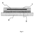
Fig. 4] Fig. 4 is a sectional view of a heretofore known solar cell module laminated body. - Hereafter, a description will be given, referring to the drawings, of an embodiment of the invention.
Fig. 1 is a sectional view showing the structure of a solar cell module laminated body according to the embodiment of the invention. InFig. 1 , the solar cell module laminated body is configured by asolar cell module 1 being supported by a supportingbody 2 across anadhesive layer 3. Asolar cell element 4 is enveloped by thesolar cell module 1. - Herein, the
adhesive layer 3 occupies one portion between thesolar cell module 1 and supportingbody 2. The portion between thesolar cell module 1 and supportingbody 2 not occupied by theadhesive layer 3 is an empty space, but a material other than the adhesive layer, for example, a drying agent or a heat transfer agent, may be packed into one portion or the whole of the empty space. - Although the form of the
adhesive layer 3 interposed between thesolar cell module 1 and supportingbody 2 is not particularly limited, a band form and circular form are suggested as preferable examples. Of these, a plane sectional view when the adhesive layer is an assembly of band-like portions is shown inFig. 2 . Also, a plane sectional view when the adhesive layer is an assembly of circular portions is shown inFig. 3 . - When the adhesive layer is disposed continuously or intermittently in a portion of a length at least one half of the overall length of the external edge portion of the solar cell module, an advantage of preventing detachment of the
solar cell module 1 from the supportingbody 2 is particularly high. - A polymeric material such as polyethylene, an ethylene-vinyl acetate copolymer, a fluorine series resin, or a polyester resin, or a metal, can be used as the material of an adhesive surface side of the
solar cell module 1. A metal plate, a resin sheet, a tile, or the like, can be used for the supportingbody 2. These may be such that the surface is covered with a material other than the main material thereof. - When both the
solar cell module 1 and supportingbody 2 are flexible, the solar cell module laminated body obtained in the invention is also flexible, meaning that there is an advantage in that there is an increase in ways of using the solar cell module laminated body, such as installing it on a curved surface portion of an external wall of a building or transporting it rolled up. - It is possible to carry out a surface treatment using a corona discharge, plasma, or the like, or apply a primer coating, on the surfaces of both the
solar cell module 1 and supportingbody 2 in order to increase adhesion to theadhesive layer 3. - In order to absorb a discrepancy in dimensional change resulting from a difference in the thermal expansion rates of the
solar cell module 1 and supportingbody 2, distortion occurring when deforming the flexible solar cell module laminated body, and the like, thus preventing damage to the adhesive interface, it is preferable that the elasticity of theadhesive layer 3 is 100 MPa or less, and in order to maintain adhesive strength, thus preventing unnecessary distortion of the solar cell module laminated body, it is preferable that the elasticity of theadhesive layer 3 is 100 kPa or more. - A reaction curing type adhesive or a pressure sensitive adhesive sheet can be used for the
adhesive layer 3. Although it is possible to use a silicone series adhesive, an acrylic adhesive, an epoxy series adhesive, or the like, as a reaction curing type adhesive, a silicone series adhesive is particularly suitable. It is possible to use a moisture curing type, a thermal curing type, a light curing type, or a two-liquid mixed curing type of adhesive as a silicone series adhesive. It is possible to use one of a butyl rubber series, acrylic foam series, or the like, as a pressure sensitive adhesive sheet, and it may also contain a film, a mesh, or the like, with an object of increasing strength, or the like. - Next, a specific description will be given of main points of the invention.
An adhesive area of theadhesive layer 3 disposed between thesolar cell module 1 and supportingbody 2 is calculated using the following Equation (1).
Herein, Aa is the minimum adhesive area necessary for theadhesive layer 3, Am is the area of thesolar cell module 1, Sd is the value of the minimum shear strength of thesolar cell module 1 and supportingbody 2 required of the solar cell module laminated body, and Sm is the value of the shear adhesive strength exerted over the whole of thesolar cell module 1 and supportingbody 2 when supposing an adhesion over the whole surface of thesolar cell module 1 using theadhesive layer 3. - The tensile shear adhesive strength of the
solar cell module 1 and supportingbody 2 of the solar cell module laminated body obtained by adhesion with theadhesive layer 3 having the adhesive area Aa calculated using Equation (1) is the tensile shear adhesive strength Sd. Also, in the case of this adhesive area, the amount of the adhesive layer is minimal, and the solar cell module laminated body cost reducing effect is high. - When there is little need to reduce the cost of the solar cell module laminated body, the adhesive area of the
adhesive layer 3 may be larger than the previously mentioned Aa calculated using Equation (1). When using anadhesive layer 3 with an adhesive area larger than the previously mentioned Aa, it is possible to obtain a solar cell module laminated body with a tensile shear adhesive strength greater than the previously mentioned Sd. - By adopting the heretofore described kind of solar cell module laminated body structure, it is possible to obtain a solar cell module laminated body with which it is possible to balance cost reduction and sufficient adhesive strength.
- Next, the invention will be further described giving Examples and Comparative Examples. Results of Example 1 and Comparative Examples are shown in Table 1, results of Example 2 and Comparative Examples in Table 2, and results of Example 3 and Comparative Examples in Table 3.
- A flexible type with a thickness of 0.85 mm is used for the solar cell module. The material of the adhesive surface side is an ethylene tetrafluoroethylene copolymer, and the surface of the adhesive surface side is plasma treated. A polyvinylidene fluoride-chlorine trifluoride vinyl copolymer sheet with a thickness of 0.58 mm is used for the supporting body. A tape-form acrylic foam series pressure sensitive adhesive sheet with a thickness of 0.4 mm and width of 12.5 mm is used for the adhesive.
- The solar cell module in Example 1 has a length of 500 mm and a width of 250 mm, meaning that the area Am of the solar cell module used in Equation (1) is 125,000 mm2.
- The shear adhesive strength Sd required of the solar cell module laminated body in Example 1, being a value set based on the installation environment and the like, is 3.0 N/cm2.
- The shear adhesive strength Sm of the tape-form acrylic foam series pressure sensitive adhesive sheet in Example 1 is calculated by bonding the solar cell module and supporting body over an adhesive area of 1 cm2 using the tape-form acrylic foam series pressure sensitive adhesive sheet and conducting a shear adhesive strength test, the result of which is 24. 0 N/cm2. Also, the price of the tape-form acrylic foam series pressure sensitive adhesive sheet is 0.4 yen per 1 cm2.
- Using Equation (1), the necessary adhesive area Aa is calculated to be 15,625 mm2. Therefore, a solar cell module laminated body is obtained by making the adhesive area 18,750 mm2 using three of the tape-form acrylic foam series pressure sensitive adhesive sheets with a length of 500 mm, and bonding the solar cell module and supporting body in the way shown in
Fig. 2 . - The price of the tape-form acrylic foam series pressure sensitive adhesive sheet used is calculated from the unit price thereof and the adhesive area to be 75 yen. Also, the result of measuring the shear adhesive strength of the solar cell module laminated body obtained is 3.5 N/cm2, exceeding the required value of 3.0 N/cm2.
- The amount of tape-form acrylic foam series pressure sensitive adhesive sheet used is changed with respect to the conditions of Example 1. A solar cell module laminated body is obtained by making the adhesive area 12,500 mm2 using two tape-form acrylic foam series pressure sensitive adhesive sheets with a length of 500 mm, and bonding in the same way as that shown in
Fig. 2 . - The price of the tape-form acrylic foam series pressure sensitive adhesive sheet used is calculated from the unit price thereof and the adhesive area to be 50 yen, lower than the 75 yen of Example 1. However, as the result of measuring the shear adhesive strength of the solar cell module laminated body obtained is 2.3 N/cm2, lower than the required value of 3.0 N/cm2, it is clear that it does not stand up to use.
- The amount of tape-form acrylic foam series pressure sensitive adhesive sheet used is changed with respect to the conditions of Example 1. A solar cell module laminated body is obtained by making the adhesive area 125, 000 mm2 using twenty tape-form acrylic foam series pressure sensitive adhesive sheets with a length of 500 mm, and bonding over the whole surface of the solar cell module.
- The result of measuring the shear adhesive strength of the solar cell module laminated body obtained is 23.1 N/cm2, exceeding the required value of 3.0 N/cm2. However, the price of the tape-form acrylic foam series pressure sensitive adhesive sheet used is calculated from the unit price thereof and the adhesive area to be 500 yen, exceeding the 75 yen of Example 1.
-
(Table 1) Shear Adhesive Strength (N/cm2) Price of Adhesive Layer Used (Yen) Example 1 3.5 75 Comparative Example 1 2.3 50 Comparative Example 2 23.1 500 - The same solar cell module and supporting body as in Example 1 are used. A moisture curing type silicone series adhesive is used for the adhesive layer, and the coating thickness is 0.5 mm. The shear adhesive strength Sd required of the solar cell module laminated body in Example 2, being a value set based on the installation environment and the like, is 2.0 N/cm2.
- The shear adhesive strength Sm of the moisture curing type silicone series adhesive in Example 2 is calculated by bonding the solar cell module and supporting body over an adhesive area of 1 cm2 using the moisture curing type silicone series adhesive and conducting a shear adhesive strength test, the result of which is 22.4 N/cm2. Also, the price when applying the moisture curing type silicone series adhesive to a thickness of 0.5 mm is 0.45 yen per 1 cm2.
- Using Equation (1), the necessary adhesive area Aa is calculated to be 11,161 mm2. Therefore, a solar cell module laminated body is obtained by making the adhesive area 12, 000 mm2, and bonding the solar cell module and supporting body in the way shown in
Fig. 3 . - The price of the moisture curing type silicone series adhesive used is calculated from the unit price thereof and the adhesive area to be 54 yen. Also, the result of measuring the shear adhesive strength of the solar cell module laminated body obtained is 2.1 N/cm2, exceeding the required value of 2.0 N/cm2.
- The amount of moisture curing type silicone series adhesive used is changed with respect to the conditions of Example 2, and a solar cell module laminated body is obtained by making the adhesive area 10, 000 cm2, and bonding in the same way as that shown in
Fig. 3 . - The price of the moisture curing type silicone series adhesive used is calculated from the unit price thereof and the adhesive area to be 45 yen, lower than the 54 yen of Example 2. However, as the result of measuring the shear adhesive strength of the solar cell module laminated body obtained is 1.7 N/cm2, lower than the required value of 2.0 N/cm2, it is clear that it does not stand up to use.
- The amount of moisture curing type silicone series adhesive used is changed with respect to the conditions of Example 2, and a solar cell module laminated body is obtained by making the adhesive area 125,000 mm2, and bonding over the whole surface of the solar cell module.
- The result of measuring the shear adhesive strength of the solar cell module laminated body obtained is 21.7 N/cm2, exceeding the required value of 2.0 N/cm2. However, the price of the moisture curing type silicone series adhesive used is calculated from the unit price thereof and the adhesive area to be 563 yen, exceeding the 54 yen of Example 2.
-
(Table 2) Shear Adhesive Strength (N/cm2) Price of Adhesive Used (Yen) Example 2 2.1 54 Comparative Example 3 1.7 45 Comparative Example 4 21.7 563 - A flexible type solar cell module with dimensions of length 500 mm, width 250 mm, thickness 0.85 mm, and area Am 125, 000 mm2 is used. The material of the adhesive surface side is an ethylene tetrafluoroethylene copolymer, and the surface of the adhesive surface side is plasma treated. A polyvinylidene fluoride-chlorine trifluoride vinyl copolymer sheet with a thickness of 0.58 mm is used for the supporting body. A tape-form acrylic foam series pressure sensitive adhesive sheet with a thickness of 0.4 mm and width of 12.5 mm is used for the adhesive.
- The shear adhesive strength Sd required of the solar cell module laminated body in Example 3, being a value set based on the installation environment and the like, is 3.0 N/cm2.
- The tensile shear adhesive strength Sm of the tape-form acrylic foam series pressure sensitive adhesive sheet in Example 3 is calculated by bonding the solar cell module and supporting body over an adhesive area of 1 cm2 using the tape-form acrylic foam series pressure sensitive adhesive sheet and conducting a shear adhesive strength test, the result of which is 24.0 N/cm2.
- Using Equation (1), the necessary minimum adhesive area Aa is calculated to be 15, 625 mm2. Therefore, the adhesive area is made 18,750 mm2 using the tape-form acrylic foam series pressure sensitive adhesive sheet, and four kinds of solar cell module laminated body are fabricated by changing the length of the
adhesive layer 3 disposed on the external edge portion of the solar cell module, and bonding the supporting body and solar cell module. The individual ratios of the length of the external edge portion on which theadhesive layer 3 is disposed with respect to the overall length of the external edge portion of the solar cell module are 30, 50, 80, and 100%. Of these, the case in which the ratio of the length of the bonded external edge portion is 100% indicates that theadhesive layer 3 is disposed over the whole of the external edge portion. - Next, using the heretofore described four laminated bodies, a weather resistance test is conducted with a weatherometer. The bonding condition of the laminated bodies is visually examined after conducting a 500 hour test under conditions of an irradiance of 78 W/m2, a temperature of 63°C, and a water spraying for 18 minutes every 120 minutes. The results thereof are shown in Table 3.
- When disposing the adhesive layer on 50% or more of the overall length of the external edge portion of the solar cell module, there is no detachment of the module. However, in the laminated body in which only 30% of the overall length of the external edge portion of the solar cell module is bonded, a detachment of 1 cm of the solar cell module and supporting body is observed in the adhesive layer. These results indicate that disposing the
adhesive layer 3 in a portion of a length one half the overall length of the external edge portion of the solar cell module has an advantage of preventing detachment of the solar cell module and supporting body. -
(Table 3) Ratio of Length of External Edge Portion on which Adhesive Layer is Disposed Result Observed After Weather Resistance Test 30% Detachment 50% No detachment 80% No detachment 100% No detachment - A module of length 500 mm, width 250m m, thickness 0.85 mm, and area Am 125,000 mm2 is used as a flexible type solar cell module. The material of the adhesive surface side is an ethylene tetrafluoroethylene copolymer, and the surface of the adhesive surface side is plasma treated. A polyvinylidene fluoride-chlorine trifluoride vinyl copolymer sheet with a thickness of 0.58 mm is used for the supporting body. A tape-form acrylic foam series pressure sensitive adhesive sheet with a thickness of 0.4 mm and width of 12.5 mm is used for the adhesive layer.
- The shear adhesive strength Sd required of the solar cell module laminated body in Example 4, being a value set based on the installation environment and the like, is 3.0 N/cm2.
- The shear adhesive strength Sm of the tape-form acrylic foam series pressure sensitive adhesive sheet in Example 4 is calculated by bonding the solar cell module and supporting body over an adhesive area of 1 cm2 using the tape-form acrylic foam series pressure sensitive adhesive sheet and conducting a shear adhesive strength test, the result of which is 24. 0 N/cm2. Also, the elasticity of the tape-form acrylic foam series pressure sensitive adhesive sheet in Example 4 is 500 kPa.
- Using Equation (1), the necessary adhesive area Aa is calculated to be 15,625 mm2. A solar cell module laminated body is obtained by making the adhesive area 18,750 mm2 using a tape-form acrylic foam series pressure sensitive adhesive sheet with a length of 500 mm, and bonding the solar cell module and supporting body.
- The solar cell module laminated body is installed vertically by the supporting body portion of the solar cell module laminated body being fixed to a building. When examining one year later, there is no deformation of the bonded portion of the solar cell module laminated body.
- The same flexible type solar cell module and supporting body as in Example 4 are used. A tape-form acrylic foam series pressure sensitive adhesive sheet with a thickness of 0.4 mm and width of 12.5 mm, and elasticity differing from that in Example 4, is used for the adhesive.
- The elasticity of the tape-form acrylic foam series pressure sensitive adhesive sheet in Example 5 is 80 kPa. The shear adhesive strength Sd required of the solar cell module laminated body in Example 5 is 3. 0 N/cm2, the same as in Example 4.
- The shear adhesive strength Sm of the tape-form acrylic foam series pressure sensitive adhesive sheet in Example 5 is calculated by bonding the solar cell module and supporting body over an adhesive area of 1 cm2 using the tape-form acrylic foam series pressure sensitive adhesive sheet and conducting a tensile shear adhesive strength test, the result of which is 24.5 N/cm2, equivalent to that in Example 4.
- A solar cell module laminated body is obtained by making the adhesive area the same 18,750 mm2 as in Example 4, and bonding the solar cell module and supporting body.
- The solar cell module laminated body is installed vertically by the supporting body portion of the solar cell module laminated body being fixed to a building. When examining one year later, the position of bonding of the solar cell module to the supporting body has slipped to approximately 1 cm below the initial position.
- The same flexible type solar cell module and supporting body as in Example 4 are used. A tape-form acrylic foam series pressure sensitive adhesive sheet with a thickness of 0.4 mm and width of 12.5 mm, and elasticity differing from that in Example 4 and Comparative Example 5, is used for the adhesive.
- The elasticity of the tape-form acrylic foam series pressure sensitive adhesive sheet in Comparative Example 6 is 110 MPa. The tensile shear adhesive strength Sd required of the solar cell module laminated body in Comparative Example 6 is 3.0 N/cm2, the same as in Example 4.
- The tensile shear adhesive strength Sm of the tape-form acrylic foam series pressure sensitive adhesive sheet in Comparative Example 6 is calculated by bonding the solar cell module and supporting body over an adhesive area of 1 cm2 using the tape-form acrylic foam series pressure sensitive adhesive sheet and conducting a tensile shear adhesive strength test, the result of which is 24.7 N/cm2, equivalent to that in Example 4.
- A solar cell module laminated body is obtained by making the adhesive area the same 18,750 mm2 as in Example 4, and bonding the solar cell module and supporting body.
- The solar cell module laminated body is installed vertically by the supporting body portion of the solar cell module laminated body being fixed to a building. When examining one year later, detachment is observed between the solar cell module and supporting body.
-
- 1
- Solar cell module
- 2
- Supporting body
- 3
- Adhesive layer
- 4
- Solar cell element
Claims (4)
- A solar cell module laminated body, characterized by including:a flexible type solar cell module; anda supporting body that supports the solar cell module,the solar cell module being bonded to the supporting body using an adhesive layer, whereinthe adhesive layer has an elasticity of 100 kPa or more, 100 MPa or less, and an adhesive area Aa thereof is determined, based on an area Am of the solar cell module, a value Sd of a shear adhesive strength required of a laminated body of the supporting body and solar cell module, and a value Sm of a shear adhesive strength of the adhesive layer and solar cell module, using the following equation

- The solar cell module laminated body according to claim 1, characterized in that
the adhesive layer is disposed continuously or intermittently to a length at least one half of the overall length of the external edge portion of the solar cell module. - The solar cell module laminated body according to claim 1 or claim 2, characterized in that
the adhesive layer is formed from a pressure sensitive adhesive. - The solar cell module laminated body according to claim 1 or claim 2, characterized in that
the adhesive layer is formed from a reaction curing type adhesive.
Applications Claiming Priority (2)
| Application Number | Priority Date | Filing Date | Title |
|---|---|---|---|
| JP2009215822A JP2011066220A (en) | 2009-09-17 | 2009-09-17 | Solar cell module laminate |
| PCT/JP2010/059235 WO2011033828A1 (en) | 2009-09-17 | 2010-06-01 | Solar cell module laminate |
Publications (1)
| Publication Number | Publication Date |
|---|---|
| EP2479799A1 true EP2479799A1 (en) | 2012-07-25 |
Family
ID=43758441
Family Applications (1)
| Application Number | Title | Priority Date | Filing Date |
|---|---|---|---|
| EP10816941A Withdrawn EP2479799A1 (en) | 2009-09-17 | 2010-06-01 | Solar cell module laminate |
Country Status (5)
| Country | Link |
|---|---|
| US (1) | US20120160305A1 (en) |
| EP (1) | EP2479799A1 (en) |
| JP (1) | JP2011066220A (en) |
| CN (1) | CN102598296A (en) |
| WO (1) | WO2011033828A1 (en) |
Families Citing this family (1)
| Publication number | Priority date | Publication date | Assignee | Title |
|---|---|---|---|---|
| CN116087095A (en) * | 2023-01-29 | 2023-05-09 | 东软睿驰汽车技术(沈阳)有限公司 | Structural adhesive testing method and device |
Family Cites Families (4)
| Publication number | Priority date | Publication date | Assignee | Title |
|---|---|---|---|---|
| JP2660138B2 (en) * | 1992-09-03 | 1997-10-08 | キヤノン株式会社 | Solar cell module |
| JP2586865B2 (en) * | 1992-09-03 | 1997-03-05 | キヤノン株式会社 | Roof material integrated solar cell and solar cell installation method |
| JP3552369B2 (en) * | 1995-10-25 | 2004-08-11 | 鐘淵化学工業株式会社 | Manufacturing method of high rigidity solar cell module |
| WO2002016721A1 (en) * | 2000-08-25 | 2002-02-28 | Asahi Glass Company, Limited | Bonding structure of vehicle window pane and method of removing vehicle window pane from bonded body |
-
2009
- 2009-09-17 JP JP2009215822A patent/JP2011066220A/en active Pending
-
2010
- 2010-06-01 CN CN201080040592XA patent/CN102598296A/en active Pending
- 2010-06-01 US US13/389,721 patent/US20120160305A1/en not_active Abandoned
- 2010-06-01 EP EP10816941A patent/EP2479799A1/en not_active Withdrawn
- 2010-06-01 WO PCT/JP2010/059235 patent/WO2011033828A1/en not_active Ceased
Non-Patent Citations (1)
| Title |
|---|
| See references of WO2011033828A1 * |
Also Published As
| Publication number | Publication date |
|---|---|
| WO2011033828A1 (en) | 2011-03-24 |
| US20120160305A1 (en) | 2012-06-28 |
| JP2011066220A (en) | 2011-03-31 |
| CN102598296A (en) | 2012-07-18 |
Similar Documents
| Publication | Publication Date | Title |
|---|---|---|
| JP5582936B2 (en) | Solar cell module | |
| US9350288B2 (en) | Photovoltaic module support clamp assembly | |
| US8420218B2 (en) | Photovoltaic modules having reduced weight | |
| KR20090100410A (en) | Solar cell backside protective sheet and solar cell module including same | |
| WO2008083164A1 (en) | Structural attachment of solar modules to frames by glazing | |
| US20050224108A1 (en) | Enhanced photovoltaic module | |
| US20090205704A1 (en) | Photovoltaic module for roofs | |
| US10381498B2 (en) | Flexible laminates for solar modules | |
| EP2584612A1 (en) | Joint structure of solar cell module and installation method for solar cell module | |
| US9239173B2 (en) | Photovoltaic module support with interface strips | |
| US20120080076A1 (en) | Photovoltaic module support with cable clamps | |
| EP2450967A1 (en) | Solar cell module and method for reinforcing solar cell module | |
| US20150357967A1 (en) | Apparatus and method of mounting and supporting a solar panel | |
| HU209222B (en) | Apparatus for utilizing solar energy by means of solar cell | |
| AU2016341146B2 (en) | Rear face element for a solar module | |
| WO2006121013A1 (en) | Solar cell module, and solar cell installation surface | |
| US20120160305A1 (en) | Solar cell module laminate body | |
| JP2000114569A (en) | Solar cell module | |
| CN102208469A (en) | Solar cell module | |
| JP4025679B2 (en) | How to install the solar cell module | |
| US11935979B2 (en) | Lightweight solar panels with solar cell structural protection | |
| JP2012156216A (en) | Fixation apparatus of solar cell module | |
| KR102944445B1 (en) | Polyurethane foam/metal conductive sheet with improved bonding strength and conductive adhesive tape containing the same | |
| JP4132023B2 (en) | Solar cell module | |
| JP5607090B2 (en) | Roof structure |
Legal Events
| Date | Code | Title | Description |
|---|---|---|---|
| PUAI | Public reference made under article 153(3) epc to a published international application that has entered the european phase |
Free format text: ORIGINAL CODE: 0009012 |
|
| 17P | Request for examination filed |
Effective date: 20120201 |
|
| AK | Designated contracting states |
Kind code of ref document: A1 Designated state(s): AL AT BE BG CH CY CZ DE DK EE ES FI FR GB GR HR HU IE IS IT LI LT LU LV MC MK MT NL NO PL PT RO SE SI SK SM TR |
|
| DAX | Request for extension of the european patent (deleted) | ||
| RIN1 | Information on inventor provided before grant (corrected) |
Inventor name: HITOMI, MIYAKO Inventor name: TANDA, MASAYUKI Inventor name: NAMIKI, YOICHI |
|
| STAA | Information on the status of an ep patent application or granted ep patent |
Free format text: STATUS: THE APPLICATION HAS BEEN WITHDRAWN |
|
| 18W | Application withdrawn |
Effective date: 20130909 |