EP2479694A2 - Automatic tooth charting using digital images - Google Patents
Automatic tooth charting using digital images Download PDFInfo
- Publication number
- EP2479694A2 EP2479694A2 EP12000277A EP12000277A EP2479694A2 EP 2479694 A2 EP2479694 A2 EP 2479694A2 EP 12000277 A EP12000277 A EP 12000277A EP 12000277 A EP12000277 A EP 12000277A EP 2479694 A2 EP2479694 A2 EP 2479694A2
- Authority
- EP
- European Patent Office
- Prior art keywords
- dental chart
- tooth
- teeth
- chart
- patient
- Prior art date
- Legal status (The legal status is an assumption and is not a legal conclusion. Google has not performed a legal analysis and makes no representation as to the accuracy of the status listed.)
- Granted
Links
Images


Classifications
-
- A—HUMAN NECESSITIES
- A61—MEDICAL OR VETERINARY SCIENCE; HYGIENE
- A61C—DENTISTRY; APPARATUS OR METHODS FOR ORAL OR DENTAL HYGIENE
- A61C19/00—Dental auxiliary appliances
-
- A—HUMAN NECESSITIES
- A61—MEDICAL OR VETERINARY SCIENCE; HYGIENE
- A61C—DENTISTRY; APPARATUS OR METHODS FOR ORAL OR DENTAL HYGIENE
- A61C9/00—Impression cups, i.e. impression trays; Impression methods
- A61C9/004—Means or methods for taking digitized impressions
- A61C9/0046—Data acquisition means or methods
-
- G—PHYSICS
- G16—INFORMATION AND COMMUNICATION TECHNOLOGY [ICT] SPECIALLY ADAPTED FOR SPECIFIC APPLICATION FIELDS
- G16H—HEALTHCARE INFORMATICS, i.e. INFORMATION AND COMMUNICATION TECHNOLOGY [ICT] SPECIALLY ADAPTED FOR THE HANDLING OR PROCESSING OF MEDICAL OR HEALTHCARE DATA
- G16H10/00—ICT specially adapted for the handling or processing of patient-related medical or healthcare data
- G16H10/60—ICT specially adapted for the handling or processing of patient-related medical or healthcare data for patient-specific data, e.g. for electronic patient records
-
- G—PHYSICS
- G16—INFORMATION AND COMMUNICATION TECHNOLOGY [ICT] SPECIALLY ADAPTED FOR SPECIFIC APPLICATION FIELDS
- G16H—HEALTHCARE INFORMATICS, i.e. INFORMATION AND COMMUNICATION TECHNOLOGY [ICT] SPECIALLY ADAPTED FOR THE HANDLING OR PROCESSING OF MEDICAL OR HEALTHCARE DATA
- G16H30/00—ICT specially adapted for the handling or processing of medical images
- G16H30/20—ICT specially adapted for the handling or processing of medical images for handling medical images, e.g. DICOM, HL7 or PACS
-
- G—PHYSICS
- G16—INFORMATION AND COMMUNICATION TECHNOLOGY [ICT] SPECIALLY ADAPTED FOR SPECIFIC APPLICATION FIELDS
- G16H—HEALTHCARE INFORMATICS, i.e. INFORMATION AND COMMUNICATION TECHNOLOGY [ICT] SPECIALLY ADAPTED FOR THE HANDLING OR PROCESSING OF MEDICAL OR HEALTHCARE DATA
- G16H30/00—ICT specially adapted for the handling or processing of medical images
- G16H30/40—ICT specially adapted for the handling or processing of medical images for processing medical images, e.g. editing
-
- A—HUMAN NECESSITIES
- A61—MEDICAL OR VETERINARY SCIENCE; HYGIENE
- A61C—DENTISTRY; APPARATUS OR METHODS FOR ORAL OR DENTAL HYGIENE
- A61C9/00—Impression cups, i.e. impression trays; Impression methods
- A61C9/004—Means or methods for taking digitized impressions
- A61C9/0046—Data acquisition means or methods
- A61C9/0086—Acoustic means or methods
-
- G—PHYSICS
- G16—INFORMATION AND COMMUNICATION TECHNOLOGY [ICT] SPECIALLY ADAPTED FOR SPECIFIC APPLICATION FIELDS
- G16H—HEALTHCARE INFORMATICS, i.e. INFORMATION AND COMMUNICATION TECHNOLOGY [ICT] SPECIALLY ADAPTED FOR THE HANDLING OR PROCESSING OF MEDICAL OR HEALTHCARE DATA
- G16H15/00—ICT specially adapted for medical reports, e.g. generation or transmission thereof
Definitions
- the invention relates generally to the field of diagnostic imaging and more particularly relates to a method and apparatus that automate the task of tooth charting in dental practice.
- Dental charts aid the dental practitioner in the systematic diagnosis, tracking, and treatment of teeth and supporting structures.
- Conventional dental charting is a largely manual process, performed by the dental practitioner with the help of a standardized paper template that allows written annotation related to each tooth to be recorded and stored in the patient's file.
- An object of the present invention is to provide a method for automatic generation of an electronic dental chart for a patient, using information obtained from analysis of any of a number of types of digital images obtained from the patient.
- Another object of the present invention is to provide a method for updating an existing electronic dental chart when new data is available from patient images or from measurements obtained from the patient.
- the present invention facilitates generation and update of dental records using data available from image analysis.
- Another advantage relates to the capability to present the same dental chart information in a conventional two-dimensional (2-D) format or in a three-dimensional (3-D) format.
- a method for generation of an electronic dental chart for a patient executed at least in part by a host processor, the method comprising: obtaining image data for each of a plurality of teeth of the patient; generating a template dental chart for the patient that represents the position of each imaged tooth with a symbol according to the obtained image data; populating the template dental chart for each imaged tooth symbol to form the electronic dental chart by: (i) associating the obtained image data to the corresponding symbol in the template dental chart for the imaged tooth; (ii) analyzing the obtained image data to identify a condition of the imaged tooth; (iii) associating at least the identified condition with the symbol for the imaged tooth; and displaying the populated electronic dental chart, wherein the displayed electronic dental chart provides a visual indication of the identified condition.
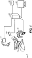
- FIG. 1 shows a dental information system 10 for obtaining patient images and generating an electronic dental chart according to an embodiment of the present invention.
- Dental information system 10 includes at least one imaging apparatus, which may be an x-ray imaging apparatus 12, a digital camera 14 such as an intra-oral camera, or a dental cone-beam computed tomography (CBCT) system 16 for generating volume images of tooth structure.
- imaging apparatus could also be employed for obtaining images of teeth and supporting structures, gums, and related tissue, such as apparatus using ultrasound or other imaging type.
- various types of diagnostic measurement instrumentation may also be provided for working with dental information system 10, as described in more detail subsequently.
- a host processor 20 such as a computer or other type of dedicated logic processor for obtaining, processing, and storing image data from the imaging apparatus is also part of dental information system 10, along with one or more displays 26 for viewing image results.
- Host processor 20 is in data communication with one or more image capture devices and, optionally, with any number of automated measurement devices.
- host processor 20 can also be in data communication with a database of patient records, stored internally or on a networked host or server, for example
- a computer-accessible memory 24 is also provided, which may be a non-volatile memory storage device used for longer term storage, such as a device using magnetic, optical, or other data storage media.
- computer-accessible memory 24 can comprise a volatile electronic memory such as a random access memory (RAM) within or otherwise in data communication with host processor 20, that is used for shorter term data storage, such as memory used in conjunction with a display device for temporarily storing image content as a display buffer, or memory that is employed to store a computer program having instructions for controlling one or more computers to practice the method according to the present invention.
- RAM random access memory
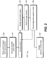
- FIG. 2 shows a sequence of process steps for generating and displaying an electronic dental chart according to one embodiment of the present invention.
- Figures 3A and 3B represent data structures that are formed in various steps of the Figure 2 sequence according to one embodiment.
- this sequence first obtains and uses a set of multiple images to form a template dental chart 40 for the patient as shown in Figure 3A .
- Template dental chart 40 shows, in outline or thumbnail form, the arrangement of teeth that have been detected from obtained images.
- template dental chart 40 is analogous to a "blank" standard dental chart that is used as a starting point for recording data for a new patient.
- template dental chart 40 is generated from images of the patient's teeth in one embodiment, using analysis of the images, and shows features that are particular to the patient, such as number of teeth, relative tooth size, and detected tooth outline and angle, as well as overall tooth condition, tooth color, and restorations and other treatments for the tooth or for specific surfaces of the tooth.
- a standardized template using conventional tooth outline symbols can alternately be used, such as with symbols 42 appropriately highlighted or otherwise marked to indicate whether or not images have been obtained for the corresponding teeth.
- one or more images needed for generating template dental chart 40 are obtained in an obtain images step 100.
- the images obtained can be any of a number of types of images, as well as combinations that include different types of images. It can be appreciated that, for this processing, at least some amount of image data content is required for a particular tooth in order for that tooth to be presented in template dental chart 40.
- the images that are obtained can be of one or more image types or modalities, including visible light images (VL), fluorescence images (F), x-ray images (X), image projections used for forming a volume image in CBCT processing, contour images, and ultrasound images.
- VL visible light images
- F fluorescence images
- X x-ray images
- image projections used for forming a volume image in CBCT processing contour images
- ultrasound images ultrasound images.
- visible light images are obtained using an intra-oral digital camera.
- a scanning sequence is carefully followed, beginning in one quadrant of the mouth and progressing along the teeth, obtaining a series of images that will be used for diagnostic purposes, with the information that has been obtained from the teeth used to populate the electronic dental chart.
- multiple images are acquired, such as images taken from different views, for example. These can alternately be images of different types, such as both visible light and fluorescence images whose combination can be used to more effectively show a caries condition.
- the collected images that are stored for an individual tooth may also include images that provide color or shade information.
- Manual entry of the tooth number or other identifier is used to associate each image with its corresponding tooth and symbol in the template in one embodiment.
- a typed entry or screen selection is used to enter the tooth number, such as selecting the corresponding symbol with a computer mouse or other pointer. Alternately, voice recognition can be used for tooth number identification.
- the obtained images are identified by the tooth number entered by the technician or are correlated to individual teeth in the patient's mouth in some other way, such as by following a set sequence of image capture steps prompted by the system, by automatic recognition in which images are analyzed and correlated to the appropriate tooth automatically, by explicit technician labeling, or by some other means.
- previously stored images can be accessed from a local or remote memory and each image associated with its corresponding symbol 42 in template dental chart 40. Tooth outline and related features from the obtained images are then used to generate the arrangement of symbols 42 in template dental chart 40 for the patient.
- Multiple template dental charts 40 can be generated for the same patient, such as using different views of the set of teeth with different symbols 42, for example, as shown in the side view of Figure 3A and the top view of Figure 3B .
- a single template could be used, with a single symbol 42 for storing and accessing one or more images for each tooth.
- a combination of templates is employed, each linked to other template views, allowing the practitioner to navigate from one template view to another by entering an instruction on the display or on a control console, for example. This provides different presentations of the patient's mouth, allowing local positioning of symbols to indicate which portion of a tooth has a restoration, for example.
- a 3-D image such as a reconstructed CBCT image
- a 3-D contour image obtained by projecting, recording, and analyzing a contour pattern or projection fringe pattern from the tooth surface, could be used for generating template dental chart 40.
- a 3-D template is provided as an alternative type of dental chart image. This can be advantageous for storing images appropriately and for accessing image data for each successive tooth.
- template dental chart 40 is generated directly from the image data.
- the chart that is generated contains symbols for only those teeth for which images have been obtained.
- the dental chart for a particular patient may appear to be incomplete, including only those teeth having images accessible to the system.
- a reduced-size image, or an outline image generated from other images of a particular tooth is used to represent the tooth as symbol 42 in template dental chart 40, rather than using a standard tooth outline pattern. Where a tooth has been extracted or is missing, there can be a corresponding blank spot or a specific symbol indicating a removed or missing tooth in template dental chart 40.
- a template population step 120 then populates the template dental chart for a set of one or more teeth by analyzing the obtained image data to identify a condition, such as caries, a restoration, or a treatment for one or more teeth in the set.
- template population step 120 loops successively through each tooth, identifies images related to the tooth in an identify images step 122, performs image analysis in an image analysis step 124, and records results in a recording step 126, associating a condition detected in image analysis step 124 with the corresponding tooth.
- the tooth condition may include detected caries as well as previous restorations or treatments, and may include a condition that is not visible, such as a root canal or implant, for example.
- Image analysis step 124 in the Figure 2 sequence can utilize any of a number of computer-aided diagnostic tools that are available for determining a tooth condition, including not only caries or other detected problem, but also restoration or previous treatment data.
- One example of an available diagnostic technique is the fluorescence imaging with reflectance enhancement (FIRE) technique taught in commonly-assigned U.S. Patent No. 7,596,253 entitled “Method And Apparatus For Detection Of Caries" to Wong et al., incorporated herein by reference.
- FIRE imaging enhancement combines both fluorescence and reflectance effects for caries detection.
- FIRE imaging techniques can also be used to identify crowns and fillings of various types, as well as to distinguish one type of filling from another. Automatic identification of various types of restorations can then be entered directly into the electronic dental chart for the patient. Operator or practitioner verification may or may not be requested for such automated entry.
- FIRE imaging In addition to FIRE imaging, other tools that can be used include visible light techniques, fluorescent light detection techniques, and automated analysis of x-ray images. Automated analysis of data from visible, fluorescent, or x-ray image data, or from some combination of image data from any number of image data sources, can be used for detection of caries and other conditions. Image processing algorithms can also detect various types of treatment applied to teeth, including sealant, implant, crown, bridge, fillings and various filling types, or other conditions. Any automatically detected condition data are stored and associated with each tooth or group of teeth. Various types of codes and symbols can be used to represent tooth conditions or treatments, automatically entered and updated as new image data for the patient is obtained.
- color shade data such as visual color values that are associated with some portion of the tooth
- HSV hue-saturation-brightness value
- CIELAB Commission Internationale de L'Éclairage L*a*b*
- image analysis step 124 can use practitioner observations, allowing annotation for entering text comments on tooth condition as well as symbols to indicate conditions or treatment that may not have been identified automatically.
- Information from panoramic x-ray image data can also be used with dental chart 40.
- Panoramic images can provide information on hidden features such as root canal treatment and implants. Image thresholding can be used to detect the presence of metal and other materials in the x-ray image.
- panoramic images can also be analyzed for tooth identification, such as by shape identification or other suitable processing, enabling a panoramic image to be automatically processed for entry of data on hidden features for one or more teeth.
- results of automated image analysis are available with each of one or more teeth. As is shown in Figure 3C , these results can be accessed and displayed from a populated electronic dental chart 50 in a display step 130.
- “hovering" or placing a mouse cursor 28 or using some other pointing element to a designated tooth symbol 42 in the displayed electronic dental chart 50 enables the display of the corresponding diagnostic results generated for the tooth using the process outlined in Figure 2 .
- a window 52 ( Figure 3C ) shows results for a specified tooth in one embodiment. This may be a pop-up window or, alternately, a dedicated area of a user interface screen for display of stored information on any selected tooth.
- the system provides a visual indication of any identified condition.
- the symbol for a selected tooth is enlarged or highlighted and different views of any selected tooth are available, such as views achieved by rotating the tooth to enable information on which portion of the tooth has been restored, for example.
- window 52 includes an optional "Notes" text field 58 for practitioner annotation of the displayed data. This also enables the practitioner to edit and correct information about the tooth that has been automatically generated.
- a link is generated between at least one tooth in the electronic dental chart 50 and the obtained image data that is stored for the at least one tooth, such as stored on a different host processor or stored in a networked database, for example.
- tooth images display as index images 56 in reduced size or "thumbnail" form, such as along the side of displayed electronic dental chart 50, as shown in Figure 4A .
- An image can be enlarged on the display when the corresponding index image 56 is selected by the practitioner.
- index images 56 scroll vertically as a computer mouse or other pointer is moved across the electronic dental chart 50 display.
- Various codes and color-coding can be used as a visual indication to indicate an identified condition of each tooth, using standardized or customized notation.
- a red color could be used to indicate a tooth requiring near-term treatment.
- Other colors could be used to indicate teeth needing particular attention or monitoring or to indicate portions of teeth having a particular type of restoration. At least a portion of this coding and notation is initially generated by computer-automated detection/diagnostics software. In one embodiment, color highlighting or indexing is used to indicate what types of images are available for each tooth.
- Embodiments of the present invention further expand upon the conventional 2-D dental chart to provide dental charting with alternative 3-D views where these views are available from CBCT imaging, from contour imaging, or from some other 3-D imaging type.
- FIG 4B there is shown, by way of example, an alternate 3-D view of a dental chart 51 that can be presented instead of, or as an alternative to, the more conventional 2-D dental chart 50 provided in Figure 4A for some portion or all of the patient's teeth.
- the viewer can switch between 2-D and 3-D viewing modes for dental chart 50 or 51 using a user interface command. This allows the system to present the same dental chart information in both a conventional 2-D format and in a 3-D format, according to viewer preference, where 3-D information is available.
- the 3-D representation can be rotated or oriented to a position that is favorable for viewing or for access to corresponding stored images.
- the 3-D information displays using a standard template.
- the 3-D display is derived from contour imaging, CBCT imaging, or other 3-D imaging of the patient.
- measurement information can also be obtained and recorded to support electronic dental chart 50.
- a practitioner command displays a measurement chart 54 that records periodontal probe measurements and entry of BPE (Basic Periodontal Examination) codes that give pocket depth values for surfaces near the teeth. Manual or automated entry of periodontal measurements can be obtained for display on chart 54.
- an automated probe is provided for generating measurement data.
- a number of types of automated probes are available for measuring periodontal pocket depth, including probes using ultrasonic, optical, or mechanical measurement devices. These devices generate a digital signal that provides the periodontal measurement data.
- an audio transcription device records the manual reading obtained by the dental practitioner, obtaining the measurement data in a "hands-free" mode of operation.
- Periodontal measurement data can be displayed graphically, enabling the practitioner to identify problems or areas of concern at a glance and to monitor trouble-spots more effectively.
- the periodontal measurements can be accessed in conjunction with information specific to a tooth.
- cursor 28 can be used to point to a tooth or area and display useful measurement information, such as in a window 56, for example.
- Electronic dental chart 50 acts as a tool for recording subsequent information and updates on tooth condition or treatment and can serve as a guide for generation of a treatment plan for the patient.
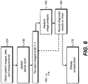
- the logic flow diagram of Figure 6 shows a sequence of steps for update of the electronic dental chart.
- An obtain images, data, and measurements step 104 enables the practitioner to update images of the patient's teeth of any type and to correlate these with the existing electronic dental chart 50. Images used can include any of the types of images that were used initially to generate electronic dental chart 50. Additional information about the tooth or about tooth treatment, such as a recent restoration, can be automatically or manually entered.
- control software prompts the dentist or dental technician to obtain an image or to provide any information about teeth for which there is currently no available image or other data.
- An update step 150 then uses this additional information to generate a revised electronic dental chart 50.
- a template population step 160 sequences through each tooth for which additional images and information have been made available.
- an image analysis step 162 is executed and results stored in a recording step 164.
- a display step 170 then displays the revised electronic dental chart, updated with the new information.
- a practitioner can enter a command to send a reminder to obtain X-rays of an area of interest upon the next patient visit or after a given time interval. This information could be used as a feed to the scheduling software that is used at the dental facility.
- the electronic dental chart of the present invention acts not only as an electronic version of the conventional paper dental chart, but also provides a convenient tool for storage of updated information on a patient's intra-oral condition and, for some aspects of diagnosis and treatment, can help to guide and organize collection of subsequent data on the patient's teeth and overall oral health.
- the electronic dental chart can cooperate with automated tools that provide images, measurement, and analysis for obtaining dental data.
- new diagnostic utilities are developed, for example, the electronic dental chart can be reconfigured to incorporate their capabilities as support utilities, helping the dental practitioner to more effectively treat patient conditions.
- fairly complete dental information about a patient can be broadcast from one site to another. This can help the patient to get the proper dental care when out of town or after moving to a new location that is not served by a particular dental practice.
Landscapes
- Health & Medical Sciences (AREA)
- Public Health (AREA)
- Epidemiology (AREA)
- General Health & Medical Sciences (AREA)
- Primary Health Care (AREA)
- Medical Informatics (AREA)
- Engineering & Computer Science (AREA)
- Veterinary Medicine (AREA)
- Animal Behavior & Ethology (AREA)
- Life Sciences & Earth Sciences (AREA)
- Dentistry (AREA)
- Oral & Maxillofacial Surgery (AREA)
- Nuclear Medicine, Radiotherapy & Molecular Imaging (AREA)
- Radiology & Medical Imaging (AREA)
- Dental Tools And Instruments Or Auxiliary Dental Instruments (AREA)
- Apparatus For Radiation Diagnosis (AREA)
- Medical Treatment And Welfare Office Work (AREA)
Abstract
Description
- The invention relates generally to the field of diagnostic imaging and more particularly relates to a method and apparatus that automate the task of tooth charting in dental practice.
- Dental charts aid the dental practitioner in the systematic diagnosis, tracking, and treatment of teeth and supporting structures. Conventional dental charting is a largely manual process, performed by the dental practitioner with the help of a standardized paper template that allows written annotation related to each tooth to be recorded and stored in the patient's file.
- With the increased use of electronic tools for image storage and display, the value of maintaining dental charts as digital data that can be displayed as needed is widely recognized. Various types of dental charting software have been developed, such as the SOFTDENT software from Kodak Dental Systems by Carestream Health.
- Refer to
U.S. Patent No. 7,010,153 entitled "Tooth Identification Digital X-Ray Images and Assignment of Information to Digital X-Ray Images" (Zimmerman). - Refer to
U.S. Patent Application Publication No. 2006/0285636 entitled "Dental Image Charting System and Method"(Razzano). - Applicants have recognized that there is a need for automatic tooth charting methods and apparatus that can generate an appropriate dental chart for a particular patient from dental images and populate the generated chart with information obtained from applying automated diagnostics to the tooth image data.
- An object of the present invention is to provide a method for automatic generation of an electronic dental chart for a patient, using information obtained from analysis of any of a number of types of digital images obtained from the patient.
- Another object of the present invention is to provide a method for updating an existing electronic dental chart when new data is available from patient images or from measurements obtained from the patient.
- Among its advantages, the present invention facilitates generation and update of dental records using data available from image analysis.
- Another advantage relates to the capability to present the same dental chart information in a conventional two-dimensional (2-D) format or in a three-dimensional (3-D) format.
- These objects are given only by way of illustrative example, and such objects may be exemplary of one or more embodiments of the invention. Other desirable objectives and advantages inherently achieved by the disclosed invention may occur or become apparent to those skilled in the art. The invention is defined by the appended claims.
- According to one aspect of the invention, there is provided a method for generation of an electronic dental chart for a patient, executed at least in part by a host processor, the method comprising: obtaining image data for each of a plurality of teeth of the patient; generating a template dental chart for the patient that represents the position of each imaged tooth with a symbol according to the obtained image data; populating the template dental chart for each imaged tooth symbol to form the electronic dental chart by: (i) associating the obtained image data to the corresponding symbol in the template dental chart for the imaged tooth; (ii) analyzing the obtained image data to identify a condition of the imaged tooth; (iii) associating at least the identified condition with the symbol for the imaged tooth; and displaying the populated electronic dental chart, wherein the displayed electronic dental chart provides a visual indication of the identified condition.
- The foregoing and other objects, features, and advantages of the invention will be apparent from the following more particular description of the embodiments of the invention, as illustrated in the accompanying drawings. The elements of the drawings are not necessarily to scale relative to each other.
-
Figure 1 is a schematic diagram showing a dental information system that generates an electronic dental chart. -
Figure 2 is a logic flow diagram that shows a process sequence for generating and displaying an electronic dental chart for one or more teeth. -
Figure 3A is a diagram that shows image data related to each of a number of teeth in an electronic dental chart. -
Figure 3B is a top view diagram that shows image data related to each of a number of teeth in an electronic dental chart according to an alternate embodiment. -
Figure 3C is a diagram that shows some of the reference data that is available for a tooth in an electronic dental chart according to one embodiment. -
Figure 4A is a user interface example showing an electronic dental chart. -
Figure 4B is a user interface example showing an alternate electronic dental chart with a 3-D representation of the patient's teeth. -
Figure 5 is an example of a chart that provides additional measurement information. -
Figure 6 is a logic flow diagram that shows a process sequence for updating an existing electronic dental chart. - The following is a detailed description of the preferred embodiments of the invention, reference being made to the drawings in which the same reference numerals identify the same elements of structure in each of the several figures.
- In the drawings and text that follow, like components are designated with like reference numerals, and similar descriptions concerning components and arrangement or interaction of components already described are omitted. Where they are used, the terms "first", "second", and so on, do not necessarily denote any ordinal or priority relation, but may simply be used to more clearly distinguish one element from another.
-
Figure 1 shows adental information system 10 for obtaining patient images and generating an electronic dental chart according to an embodiment of the present invention.Dental information system 10 includes at least one imaging apparatus, which may be anx-ray imaging apparatus 12, adigital camera 14 such as an intra-oral camera, or a dental cone-beam computed tomography (CBCT)system 16 for generating volume images of tooth structure. Other types of imaging apparatus could also be employed for obtaining images of teeth and supporting structures, gums, and related tissue, such as apparatus using ultrasound or other imaging type. In addition, various types of diagnostic measurement instrumentation may also be provided for working withdental information system 10, as described in more detail subsequently. - Still referring to
Figure 1 , ahost processor 20, such as a computer or other type of dedicated logic processor for obtaining, processing, and storing image data from the imaging apparatus is also part ofdental information system 10, along with one ormore displays 26 for viewing image results.Host processor 20 is in data communication with one or more image capture devices and, optionally, with any number of automated measurement devices. In addition,host processor 20 can also be in data communication with a database of patient records, stored internally or on a networked host or server, for example A computer-accessible memory 24 is also provided, which may be a non-volatile memory storage device used for longer term storage, such as a device using magnetic, optical, or other data storage media. In addition, computer-accessible memory 24 can comprise a volatile electronic memory such as a random access memory (RAM) within or otherwise in data communication withhost processor 20, that is used for shorter term data storage, such as memory used in conjunction with a display device for temporarily storing image content as a display buffer, or memory that is employed to store a computer program having instructions for controlling one or more computers to practice the method according to the present invention. - The logic flow diagram of
Figure 2 shows a sequence of process steps for generating and displaying an electronic dental chart according to one embodiment of the present invention.Figures 3A and3B represent data structures that are formed in various steps of theFigure 2 sequence according to one embodiment. In brief, this sequence first obtains and uses a set of multiple images to form a template dental chart 40 for the patient as shown inFigure 3A . Template dental chart 40 shows, in outline or thumbnail form, the arrangement of teeth that have been detected from obtained images. In this way, template dental chart 40 is analogous to a "blank" standard dental chart that is used as a starting point for recording data for a new patient. There is asymbol 42 for each imaged tooth in template dental chart 40. Unlike a standard printed blank dental chart, however, template dental chart 40 is generated from images of the patient's teeth in one embodiment, using analysis of the images, and shows features that are particular to the patient, such as number of teeth, relative tooth size, and detected tooth outline and angle, as well as overall tooth condition, tooth color, and restorations and other treatments for the tooth or for specific surfaces of the tooth. A standardized template using conventional tooth outline symbols can alternately be used, such as withsymbols 42 appropriately highlighted or otherwise marked to indicate whether or not images have been obtained for the corresponding teeth. - Referring to the logic flow shown in
Figure 2 , one or more images needed for generating template dental chart 40 are obtained in an obtainimages step 100. The images obtained can be any of a number of types of images, as well as combinations that include different types of images. It can be appreciated that, for this processing, at least some amount of image data content is required for a particular tooth in order for that tooth to be presented in template dental chart 40. - As is shown by example for a partial template chart in
Figure 3A and in the alternate top view ofFigure 3B , the images that are obtained can be of one or more image types or modalities, including visible light images (VL), fluorescence images (F), x-ray images (X), image projections used for forming a volume image in CBCT processing, contour images, and ultrasound images. Images obtained directly on digital detectors as well as images from scanned film or storage phosphor media can be used in this way, each image indexed to thesymbol 42 for the corresponding tooth. In one embodiment, visible light images are obtained using an intra-oral digital camera. A scanning sequence is carefully followed, beginning in one quadrant of the mouth and progressing along the teeth, obtaining a series of images that will be used for diagnostic purposes, with the information that has been obtained from the teeth used to populate the electronic dental chart. For at least one tooth, multiple images are acquired, such as images taken from different views, for example. These can alternately be images of different types, such as both visible light and fluorescence images whose combination can be used to more effectively show a caries condition. The collected images that are stored for an individual tooth may also include images that provide color or shade information. Manual entry of the tooth number or other identifier is used to associate each image with its corresponding tooth and symbol in the template in one embodiment. A typed entry or screen selection is used to enter the tooth number, such as selecting the corresponding symbol with a computer mouse or other pointer. Alternately, voice recognition can be used for tooth number identification. - In a template generation step 110 (
Figure 2 ), the obtained images are identified by the tooth number entered by the technician or are correlated to individual teeth in the patient's mouth in some other way, such as by following a set sequence of image capture steps prompted by the system, by automatic recognition in which images are analyzed and correlated to the appropriate tooth automatically, by explicit technician labeling, or by some other means. In one embodiment, previously stored images can be accessed from a local or remote memory and each image associated with itscorresponding symbol 42 in template dental chart 40. Tooth outline and related features from the obtained images are then used to generate the arrangement ofsymbols 42 in template dental chart 40 for the patient. Multiple template dental charts 40 can be generated for the same patient, such as using different views of the set of teeth withdifferent symbols 42, for example, as shown in the side view ofFigure 3A and the top view ofFigure 3B . Alternately, a single template could be used, with asingle symbol 42 for storing and accessing one or more images for each tooth. In one embodiment, a combination of templates is employed, each linked to other template views, allowing the practitioner to navigate from one template view to another by entering an instruction on the display or on a control console, for example. This provides different presentations of the patient's mouth, allowing local positioning of symbols to indicate which portion of a tooth has a restoration, for example. - In addition to use of 2-D images, a 3-D image, such as a reconstructed CBCT image, can be used as a basis for generating at least some portion of template dental chart 40. Alternately, a 3-D contour image, obtained by projecting, recording, and analyzing a contour pattern or projection fringe pattern from the tooth surface, could be used for generating template dental chart 40. In one embodiment, a 3-D template is provided as an alternative type of dental chart image. This can be advantageous for storing images appropriately and for accessing image data for each successive tooth.
- In one embodiment, template dental chart 40 is generated directly from the image data. The chart that is generated contains symbols for only those teeth for which images have been obtained. Thus, the dental chart for a particular patient may appear to be incomplete, including only those teeth having images accessible to the system. A reduced-size image, or an outline image generated from other images of a particular tooth, is used to represent the tooth as
symbol 42 in template dental chart 40, rather than using a standard tooth outline pattern. Where a tooth has been extracted or is missing, there can be a corresponding blank spot or a specific symbol indicating a removed or missing tooth in template dental chart 40. - Still referring to the sequence of
Figure 2 , a template population step 120 then populates the template dental chart for a set of one or more teeth by analyzing the obtained image data to identify a condition, such as caries, a restoration, or a treatment for one or more teeth in the set. In the example process shown inFigure 3A , template population step 120 loops successively through each tooth, identifies images related to the tooth in an identify images step 122, performs image analysis in animage analysis step 124, and records results in arecording step 126, associating a condition detected inimage analysis step 124 with the corresponding tooth. The tooth condition may include detected caries as well as previous restorations or treatments, and may include a condition that is not visible, such as a root canal or implant, for example. -
Image analysis step 124 in theFigure 2 sequence can utilize any of a number of computer-aided diagnostic tools that are available for determining a tooth condition, including not only caries or other detected problem, but also restoration or previous treatment data. One example of an available diagnostic technique is the fluorescence imaging with reflectance enhancement (FIRE) technique taught in commonly-assignedU.S. Patent No. 7,596,253 entitled "Method And Apparatus For Detection Of Caries" to Wong et al., incorporated herein by reference. FIRE imaging enhancement combines both fluorescence and reflectance effects for caries detection. FIRE imaging techniques can also be used to identify crowns and fillings of various types, as well as to distinguish one type of filling from another. Automatic identification of various types of restorations can then be entered directly into the electronic dental chart for the patient. Operator or practitioner verification may or may not be requested for such automated entry. - In addition to FIRE imaging, other tools that can be used include visible light techniques, fluorescent light detection techniques, and automated analysis of x-ray images. Automated analysis of data from visible, fluorescent, or x-ray image data, or from some combination of image data from any number of image data sources, can be used for detection of caries and other conditions. Image processing algorithms can also detect various types of treatment applied to teeth, including sealant, implant, crown, bridge, fillings and various filling types, or other conditions. Any automatically detected condition data are stored and associated with each tooth or group of teeth. Various types of codes and symbols can be used to represent tooth conditions or treatments, automatically entered and updated as new image data for the patient is obtained.
- In addition to diagnostic data, color shade data, such as visual color values that are associated with some portion of the tooth, can be stored. These can be values from a standard color space, such as hue-saturation-brightness value (HSV) or Commission Internationale de L'Éclairage L*a*b* (CIELAB) color space, for example.
- Alternately,
image analysis step 124 can use practitioner observations, allowing annotation for entering text comments on tooth condition as well as symbols to indicate conditions or treatment that may not have been identified automatically. - Information from panoramic x-ray image data can also be used with dental chart 40. Panoramic images can provide information on hidden features such as root canal treatment and implants. Image thresholding can be used to detect the presence of metal and other materials in the x-ray image. In addition, panoramic images can also be analyzed for tooth identification, such as by shape identification or other suitable processing, enabling a panoramic image to be automatically processed for entry of data on hidden features for one or more teeth.
- Following recording step 126 (
Figure 2 ), the results of automated image analysis are available with each of one or more teeth. As is shown inFigure 3C , these results can be accessed and displayed from a populated electronicdental chart 50 in adisplay step 130. In the example ofFigure 3C , "hovering" or placing amouse cursor 28 or using some other pointing element to a designatedtooth symbol 42 in the displayed electronicdental chart 50 enables the display of the corresponding diagnostic results generated for the tooth using the process outlined inFigure 2 . A window 52 (Figure 3C ) shows results for a specified tooth in one embodiment. This may be a pop-up window or, alternately, a dedicated area of a user interface screen for display of stored information on any selected tooth. The system provides a visual indication of any identified condition. In one embodiment, the symbol for a selected tooth is enlarged or highlighted and different views of any selected tooth are available, such as views achieved by rotating the tooth to enable information on which portion of the tooth has been restored, for example. - It can be appreciated that further information can alternately be added, based on practitioner observations or on measured data, including data not associated with a particular image. The dental practitioner may want to enter additional data relevant to a tooth in electronic
dental chart 50, such as by typed or audible entry. Alternately, scanned notes or other data could also be provided and linked with electronicdental chart 50. - As is shown in
Figure 3C ,window 52 includes an optional "Notes"text field 58 for practitioner annotation of the displayed data. This also enables the practitioner to edit and correct information about the tooth that has been automatically generated. - In one embodiment, a link is generated between at least one tooth in the electronic
dental chart 50 and the obtained image data that is stored for the at least one tooth, such as stored on a different host processor or stored in a networked database, for example. In the electronic dental chart, tooth images display asindex images 56 in reduced size or "thumbnail" form, such as along the side of displayed electronicdental chart 50, as shown inFigure 4A . An image can be enlarged on the display when the correspondingindex image 56 is selected by the practitioner. In one embodiment,index images 56 scroll vertically as a computer mouse or other pointer is moved across the electronicdental chart 50 display. Various codes and color-coding can be used as a visual indication to indicate an identified condition of each tooth, using standardized or customized notation. For example, a red color could be used to indicate a tooth requiring near-term treatment. Other colors could be used to indicate teeth needing particular attention or monitoring or to indicate portions of teeth having a particular type of restoration. At least a portion of this coding and notation is initially generated by computer-automated detection/diagnostics software. In one embodiment, color highlighting or indexing is used to indicate what types of images are available for each tooth. - Embodiments of the present invention further expand upon the conventional 2-D dental chart to provide dental charting with alternative 3-D views where these views are available from CBCT imaging, from contour imaging, or from some other 3-D imaging type. Referring to
Figure 4B , there is shown, by way of example, an alternate 3-D view of adental chart 51 that can be presented instead of, or as an alternative to, the more conventional 2-Ddental chart 50 provided inFigure 4A for some portion or all of the patient's teeth. In one embodiment, the viewer can switch between 2-D and 3-D viewing modes fordental chart - In one embodiment, the 3-D information displays using a standard template. In another embodiment, the 3-D display is derived from contour imaging, CBCT imaging, or other 3-D imaging of the patient.
- In addition to information obtained from digital images of the tooth, measurement information can also be obtained and recorded to support electronic
dental chart 50. A practitioner command displays ameasurement chart 54 that records periodontal probe measurements and entry of BPE (Basic Periodontal Examination) codes that give pocket depth values for surfaces near the teeth. Manual or automated entry of periodontal measurements can be obtained for display onchart 54. In one embodiment, an automated probe is provided for generating measurement data. A number of types of automated probes are available for measuring periodontal pocket depth, including probes using ultrasonic, optical, or mechanical measurement devices. These devices generate a digital signal that provides the periodontal measurement data. In another embodiment, an audio transcription device records the manual reading obtained by the dental practitioner, obtaining the measurement data in a "hands-free" mode of operation. Manual entry of BPE codes or other related values is another option. One advantage in using the display for this purpose is that periodontal measurement data can be displayed graphically, enabling the practitioner to identify problems or areas of concern at a glance and to monitor trouble-spots more effectively. In addition, the periodontal measurements can be accessed in conjunction with information specific to a tooth. As with tooth information obtained from image content,cursor 28 can be used to point to a tooth or area and display useful measurement information, such as in awindow 56, for example. - Once electronic
dental chart 50 has been generated, it can be used to support and improve treatment work flow. Electronicdental chart 50 acts as a tool for recording subsequent information and updates on tooth condition or treatment and can serve as a guide for generation of a treatment plan for the patient. The logic flow diagram ofFigure 6 shows a sequence of steps for update of the electronic dental chart. An obtain images, data, and measurements step 104 enables the practitioner to update images of the patient's teeth of any type and to correlate these with the existing electronicdental chart 50. Images used can include any of the types of images that were used initially to generate electronicdental chart 50. Additional information about the tooth or about tooth treatment, such as a recent restoration, can be automatically or manually entered. In one embodiment, control software prompts the dentist or dental technician to obtain an image or to provide any information about teeth for which there is currently no available image or other data. Anupdate step 150 then uses this additional information to generate a revised electronicdental chart 50. Atemplate population step 160 sequences through each tooth for which additional images and information have been made available. For each tooth, animage analysis step 162 is executed and results stored in arecording step 164. A display step 170 then displays the revised electronic dental chart, updated with the new information. - Among features available using the electronic dental chart are links to timing and scheduling software and utilities. For example, a practitioner can enter a command to send a reminder to obtain X-rays of an area of interest upon the next patient visit or after a given time interval. This information could be used as a feed to the scheduling software that is used at the dental facility.
- It can be seen that the electronic dental chart of the present invention acts not only as an electronic version of the conventional paper dental chart, but also provides a convenient tool for storage of updated information on a patient's intra-oral condition and, for some aspects of diagnosis and treatment, can help to guide and organize collection of subsequent data on the patient's teeth and overall oral health. The electronic dental chart can cooperate with automated tools that provide images, measurement, and analysis for obtaining dental data. As new diagnostic utilities are developed, for example, the electronic dental chart can be reconfigured to incorporate their capabilities as support utilities, helping the dental practitioner to more effectively treat patient conditions. As another advantage, fairly complete dental information about a patient can be broadcast from one site to another. This can help the patient to get the proper dental care when out of town or after moving to a new location that is not served by a particular dental practice.
- The invention has been described in detail with particular reference to a presently preferred embodiment, but it will be understood that variations and modifications can be effected within the spirit and scope of the invention. The presently disclosed embodiments are therefore considered in all respects to be illustrative and not restrictive. The scope of the invention is indicated by the appended claims, and all changes that come within the meaning and range of equivalents thereof are intended to be embraced therein.
Claims (15)
- A method for generating an electronic dental chart for a patient, executed at least in part by a processor, comprising:obtaining image data for each of a plurality of teeth of the patient;generating a template dental chart for the patient representing the position of each of the plurality of teeth with a symbol according to the obtained image data;populating the template dental chart for each symbol to form the electronic dental chart by, for each of the plurality of teeth:(i) associating the obtained image data to the corresponding symbol in the template dental chart for the tooth;(ii) analyzing the obtained image data to identify a condition of the tooth; and(iii) associating the identified condition with the symbol for the tooth; anddisplaying the populated electronic dental chart, wherein the displayed electronic dental chart provides a visual indication of the identified condition.
- The method of claim 1 wherein obtaining image data comprises obtaining image data from one or more of a digital camera, an x-ray system, a cone-beam computed tomography system, and an ultrasound system.
- The method of claim 1 wherein displaying the electronic dental chart further comprises displaying images associated with at least one of the plurality of teeth according to the position of a pointer on the displayed electronic dental chart.
- The method of claim 1 further comprising annotating entries on the electronic dental chart according to information provided by a dental practitioner about at least one of the plurality of teeth.
- The method of claim 1 wherein populating the template dental chart further comprises obtaining and storing periodontal measurement data that relates to the electronic dental chart.
- The method of claim 5 wherein the periodontal measurement data is obtained from a digital signal.
- The method of claim 1 further comprising recording an instruction to schedule image acquisition during a subsequent patient visit.
- The method of claim 1 wherein generating the template dental chart comprises processing an image for the tooth to obtain an outline image.
- The method of claim 1 wherein generating the template dental chart comprises generating a three-dimensional dental image.
- The method of claim 1 further comprising storing one or more values that represent a color shade for the at least one tooth.
- The method of claim 1 further comprising updating the electronic dental chart for the patient for one or more teeth by:obtaining digital image data for at least one image for at least one tooth of the patient;analyzing the at least one obtained image to identify a condition of the imaged tooth;associating at least the identified condition with the symbol for the imaged tooth in the electronic dental chart to form an updated dental chart; anddisplaying the updated electronic dental chart.
- The method of claim 1 wherein populating the template dental chart is performed, at least in part, by an automated procedure.
- The method of claim 1 further comprising indicating the position of one or more missing teeth on the template dental chart.
- The method of claim 1 wherein the obtained image data is a panoramic x-ray image.
- A method for displaying dental images for a patient, the method comprising:obtaining digital image data for each of a plurality of teeth of the patient;generating a template dental chart for the patient that represents the position of each of the plurality of teeth with a symbol that is generated from the obtained image data;populating the generated template dental chart for each of the plurality of teeth to form an electronic dental chart that relates the obtained image data to the corresponding symbol for each of the plurality of teeth; and displaying the electronic dental chart and displaying, along with the electronic dental chart, one or more index images related to symbols on the electronic dental chart according to viewer selection.
Applications Claiming Priority (1)
| Application Number | Priority Date | Filing Date | Title |
|---|---|---|---|
| US13/010,031 US8416984B2 (en) | 2011-01-20 | 2011-01-20 | Automatic tooth charting using digital images |
Publications (3)
| Publication Number | Publication Date |
|---|---|
| EP2479694A2 true EP2479694A2 (en) | 2012-07-25 |
| EP2479694A3 EP2479694A3 (en) | 2013-09-04 |
| EP2479694B1 EP2479694B1 (en) | 2020-09-23 |
Family
ID=45654751
Family Applications (1)
| Application Number | Title | Priority Date | Filing Date |
|---|---|---|---|
| EP12000277.9A Active EP2479694B1 (en) | 2011-01-20 | 2012-01-18 | Automatic tooth charting using digital images |
Country Status (4)
| Country | Link |
|---|---|
| US (1) | US8416984B2 (en) |
| EP (1) | EP2479694B1 (en) |
| JP (1) | JP6099310B2 (en) |
| ES (1) | ES2827295T3 (en) |
Cited By (5)
| Publication number | Priority date | Publication date | Assignee | Title |
|---|---|---|---|---|
| WO2014165553A3 (en) * | 2013-04-05 | 2014-12-11 | Marshfield Clinic Health System, Inc | Systems and methods for tooth charting |
| WO2017093563A1 (en) * | 2015-12-04 | 2017-06-08 | 3Shape A/S | Deriving tooth condition information for populating digital dental charts |
| WO2018167530A1 (en) * | 2017-03-17 | 2018-09-20 | Trophy | Dynamic dental arch map |
| CN109035386A (en) * | 2018-06-22 | 2018-12-18 | 泰康保险集团股份有限公司 | A kind of gear division VR imaging method and device |
| EP3915510B1 (en) * | 2019-02-20 | 2025-09-24 | Osstemimplant Co., Ltd. | Dental formula information input method, dental formula information input device, and recording medium with the corresponding programm. |
Families Citing this family (66)
| Publication number | Priority date | Publication date | Assignee | Title |
|---|---|---|---|---|
| EP2569748A4 (en) * | 2010-05-13 | 2015-11-04 | Quantum Dental Technologies Inc | Method of processing and displaying oral health diagnostic data |
| US8712181B2 (en) * | 2011-06-14 | 2014-04-29 | Apteryx, Inc. | Real-time application of filters based on image attributes |
| US20140091001A1 (en) * | 2012-10-02 | 2014-04-03 | Karen Lai-Ting CHAN | Reminder System Associated with a Consumer Product |
| DE102012219865B3 (en) * | 2012-10-30 | 2014-03-13 | Sirona Dental Systems Gmbh | Method for determining at least one relevant individual image of a dental object |
| JP6253665B2 (en) | 2012-12-24 | 2017-12-27 | デンタリテック ジー.ピー.エル. リミテッド | Device for measuring tooth area |
| JP5744084B2 (en) * | 2013-03-06 | 2015-07-01 | 株式会社モリタ製作所 | Dental image display device, dental treatment device, and method of operating dental image display device |
| US10090070B2 (en) * | 2013-04-26 | 2018-10-02 | Hisham Badawi | Electronic dental charting |
| US9158889B2 (en) * | 2013-04-26 | 2015-10-13 | Oral4D Systems Ltd. | Electronic dental charting |
| US9675419B2 (en) | 2013-08-21 | 2017-06-13 | Brachium, Inc. | System and method for automating medical procedures |
| EP2904988B1 (en) * | 2014-02-05 | 2020-04-01 | Sirona Dental Systems GmbH | Method for intraoral three-dimensional measurement |
| US10673922B2 (en) * | 2014-02-19 | 2020-06-02 | RealCloud Imaging Inc. | Cloud based 2D dental imaging system with HTML web browser acquisition |
| US20150294066A1 (en) * | 2014-04-09 | 2015-10-15 | Douglas A. Golay | Combination dental imaging system and dental practice management and charting system with a bi-directional communication interface |
| US10572625B2 (en) * | 2014-04-09 | 2020-02-25 | RealCloud Imaging Inc. | Combination dental imaging system and dental practice management and charting system with a bi-directional communication interface |
| JP6448921B2 (en) * | 2014-06-05 | 2019-01-09 | キヤノンメディカルシステムズ株式会社 | Electronic medical record real pseudo storage device |
| US9870613B2 (en) * | 2014-11-05 | 2018-01-16 | Carestream Health, Inc. | Detection of tooth condition using reflectance images with red and green fluorescence |
| US11426062B2 (en) * | 2014-12-17 | 2022-08-30 | Carestream Health, Inc. | Intra-oral 3-D fluorescence imaging |
| US12259231B2 (en) | 2015-01-18 | 2025-03-25 | Dentlytec G.P.L. Ltd. | Intraoral scanner |
| WO2017125926A2 (en) | 2016-01-18 | 2017-07-27 | Dentlytec G.P.L. Ltd | Intraoral scanner |
| EP3288486B1 (en) | 2015-05-01 | 2020-01-15 | Dentlytec G.P.L. Ltd. | System for dental digital impressions |
| US10445390B2 (en) * | 2015-08-14 | 2019-10-15 | Carol A. CUNNINGHAM | Coordination of dental implant information |
| US20170124043A1 (en) | 2015-11-02 | 2017-05-04 | Microsoft Technology Licensing, Llc | Sound associated with cells in spreadsheets |
| US9990350B2 (en) | 2015-11-02 | 2018-06-05 | Microsoft Technology Licensing, Llc | Videos associated with cells in spreadsheets |
| US20170168812A1 (en) * | 2015-12-13 | 2017-06-15 | Douglas A. Golay | Integration of non-supported dental imaging devices into legacy and proprietary dental imaging software |
| WO2017130060A1 (en) * | 2016-01-26 | 2017-08-03 | Ciriello Christopher John | Automated dental treatment system |
| EP4437943B1 (en) | 2016-02-24 | 2026-04-15 | 3Shape A/S | Detecting and monitoring development of a dental condition |
| WO2017216803A1 (en) | 2016-06-16 | 2017-12-21 | Safesac Medical Ltd. | Tissue containment device for use in surgical procedures |
| EP3496654B1 (en) | 2016-08-15 | 2020-05-06 | Trophy | Dynamic dental arch map |
| EP3509501B1 (en) | 2016-09-10 | 2025-06-25 | Ark Surgical Ltd. | Laparoscopic workspace device |
| US12285188B2 (en) | 2016-09-10 | 2025-04-29 | Ark Surgical Ltd. | Laparoscopic workspace device |
| JP6749193B2 (en) * | 2016-09-27 | 2020-09-02 | 株式会社アドバンスト・メディア | Finding creation device, finding creation method, finding creation program, and recording medium recording the same |
| JP7097545B2 (en) * | 2016-10-13 | 2022-07-08 | メディア株式会社 | Image analysis system |
| EP3648703B1 (en) | 2017-07-04 | 2023-04-26 | Dentlytec G.P.L. Ltd. | Dental scanner with ultrasonic sensor component for augmentation of optical data |
| US11690701B2 (en) | 2017-07-26 | 2023-07-04 | Dentlytec G.P.L. Ltd. | Intraoral scanner |
| US11154375B2 (en) | 2018-02-02 | 2021-10-26 | Brachium, Inc. | Medical robotic work station |
| AU2018282326A1 (en) * | 2018-02-07 | 2019-08-22 | Animal Dental Chart Inc. | System and methods for animal dental charting |
| CA179646S (en) | 2018-02-07 | 2022-03-07 | Animal Dental Chart Inc | Display screen with graphical user interface |
| AU2019266407A1 (en) | 2018-05-10 | 2021-01-07 | Cyberdontics (Usa), Inc. | Automated dental drill |
| CA3100495A1 (en) * | 2018-05-16 | 2019-11-21 | Benevis Informatics, Llc | Systems and methods for review of computer-aided detection of pathology in images |
| JP6996625B2 (en) * | 2018-06-13 | 2022-01-17 | 富士通株式会社 | Programs, information processing equipment and information processing methods |
| US11389131B2 (en) | 2018-06-27 | 2022-07-19 | Denti.Ai Technology Inc. | Systems and methods for processing of dental images |
| KR20200007602A (en) * | 2018-07-13 | 2020-01-22 | 김태훈 | Oral care device and oral care service system |
| US10991091B2 (en) * | 2018-10-30 | 2021-04-27 | Diagnocat Inc. | System and method for an automated parsing pipeline for anatomical localization and condition classification |
| US12555283B2 (en) * | 2018-10-30 | 2026-02-17 | Matvey Dmitrievich Ezhov | Systems and methods for generating quick-glance interactive diagnostic reports |
| US11464467B2 (en) * | 2018-10-30 | 2022-10-11 | Dgnct Llc | Automated tooth localization, enumeration, and diagnostic system and method |
| ES3052991T3 (en) | 2018-12-28 | 2026-01-16 | Nobel Biocare Services Ag | Apparatus for generating a 3d model image of a patient's dentition |
| WO2020144692A2 (en) * | 2019-01-09 | 2020-07-16 | Dentlytec G.P.L. Ltd | Dental device with probe and methods associated therewith |
| WO2020161301A1 (en) * | 2019-02-07 | 2020-08-13 | Trophy Sas | Method and apparatus for training automatic tooth charting systems |
| US11366985B2 (en) * | 2020-05-15 | 2022-06-21 | Retrace Labs | Dental image quality prediction platform using domain specific artificial intelligence |
| US11311247B2 (en) * | 2019-06-27 | 2022-04-26 | Retrace Labs | System and methods for restorative dentistry treatment planning using adversarial learning |
| US11367188B2 (en) * | 2019-10-18 | 2022-06-21 | Retrace Labs | Dental image synthesis using generative adversarial networks with semantic activation blocks |
| US11217350B2 (en) | 2019-06-27 | 2022-01-04 | Retrace Labs | Systems and method for artificial-intelligence-based dental image to text generation |
| US20210358604A1 (en) * | 2020-05-15 | 2021-11-18 | Retrace Labs | Interface For Generating Workflows Operating On Processing Dental Information From Artificial Intelligence |
| US20200411167A1 (en) * | 2019-06-27 | 2020-12-31 | Retrace Labs | Automated Dental Patient Identification And Duplicate Content Extraction Using Adversarial Learning |
| US11189028B1 (en) | 2020-05-15 | 2021-11-30 | Retrace Labs | AI platform for pixel spacing, distance, and volumetric predictions from dental images |
| US11276151B2 (en) * | 2019-06-27 | 2022-03-15 | Retrace Labs | Inpainting dental images with missing anatomy |
| US11357604B2 (en) | 2020-05-15 | 2022-06-14 | Retrace Labs | Artificial intelligence platform for determining dental readiness |
| US11348237B2 (en) * | 2019-05-16 | 2022-05-31 | Retrace Labs | Artificial intelligence architecture for identification of periodontal features |
| US11398013B2 (en) * | 2019-10-18 | 2022-07-26 | Retrace Labs | Generative adversarial network for dental image super-resolution, image sharpening, and denoising |
| US12465464B2 (en) * | 2019-12-04 | 2025-11-11 | Dental Imaging Technologies Corporation | Intraoral 3D scanning with automatic charting |
| KR102877625B1 (en) * | 2020-05-15 | 2025-10-29 | 한국 한의학 연구원 | Method and system for inputting acupoint to electronic medical record for oriental medicine hospital based patient's images |
| CN111914975B (en) * | 2020-08-06 | 2024-08-16 | 深圳开立生物医疗科技股份有限公司 | Color-level bar generation method, device, equipment and readable storage medium |
| CN116801810A (en) | 2020-09-03 | 2023-09-22 | 网络牙科(美国)公司 | Methods and apparatus for CNA analysis of dental anatomy |
| JP7801345B2 (en) | 2020-12-17 | 2026-01-16 | アーク サージカル リミテッド | Laparoscopic tissue containment device |
| KR102544203B1 (en) * | 2021-04-22 | 2023-06-16 | 주식회사 메디트 | An intraoral image processing apparatus, an intraoral image processing method |
| JP2022183026A (en) * | 2021-05-27 | 2022-12-08 | メディア株式会社 | System for dental care recording and explanation to patient, and care record sheet |
| US20240366319A1 (en) | 2023-05-04 | 2024-11-07 | Perceptive Technologies, Inc. | Robotic Dental System and Method of Preparing for a Robotic Dental Procedure |
Citations (3)
| Publication number | Priority date | Publication date | Assignee | Title |
|---|---|---|---|---|
| US7010153B2 (en) | 2001-02-21 | 2006-03-07 | Sirona Dental Systems Gmbh | Tooth identification digital X-ray images and assignment of information to digital X-ray images |
| US20060285636A1 (en) | 2004-09-29 | 2006-12-21 | Interactive Diagnostic Imaging, Inc. | Dental image charting system and method |
| US7596253B2 (en) | 2005-10-31 | 2009-09-29 | Carestream Health, Inc. | Method and apparatus for detection of caries |
Family Cites Families (14)
| Publication number | Priority date | Publication date | Assignee | Title |
|---|---|---|---|---|
| JPH1097404A (en) * | 1996-09-20 | 1998-04-14 | Sanyo Electric Co Ltd | Computer system |
| US7507088B2 (en) | 1997-09-30 | 2009-03-24 | Cadent Ltd. | Method for comparing orthodontic element placement |
| US6532299B1 (en) * | 2000-04-28 | 2003-03-11 | Orametrix, Inc. | System and method for mapping a surface |
| JP2002224148A (en) * | 2001-01-30 | 2002-08-13 | Hiromoto Namikawa | Method for assisting oral situation determination, assistance apparatus for determining oral situation, and program for assisting oral situation determination |
| US7343305B2 (en) | 2001-05-03 | 2008-03-11 | University Of Florida Research Foundation, Inc. | Method and system for recording carious lesions |
| JP2003167957A (en) * | 2001-12-04 | 2003-06-13 | Hitachi Ltd | Medical information management method and medical information management system |
| JP2004033663A (en) * | 2002-07-08 | 2004-02-05 | Yoshinori Nodera | Support system for dental treatment of pet animal by dentist |
| US20040049956A1 (en) * | 2002-09-16 | 2004-03-18 | Xiang-Long Li | System for personalized collection of baby teeth |
| US20040254478A1 (en) * | 2003-05-22 | 2004-12-16 | De Josselin De Jong Elbert | Fluorescence filter for tissue examination and imaging |
| JP2005196662A (en) * | 2004-01-09 | 2005-07-21 | Hitachi Medical Corp | Dental practice support device |
| AU2006230551A1 (en) * | 2005-03-31 | 2006-10-05 | Perio-Imaging Inc. | Ultrasonic periodontal system and method of using |
| JP5210616B2 (en) * | 2007-12-14 | 2013-06-12 | 日立メディカルコンピュータ株式会社 | Medical image diagnosis support apparatus and medical image diagnosis support program |
| US20090214089A1 (en) * | 2008-02-27 | 2009-08-27 | Therametric Technologies, Inc. | System and Method for Data Analysis And Capture |
| US9710603B2 (en) * | 2008-11-12 | 2017-07-18 | Softech, Inc. | Dental charting system |
-
2011
- 2011-01-20 US US13/010,031 patent/US8416984B2/en active Active
-
2012
- 2012-01-11 JP JP2012002721A patent/JP6099310B2/en active Active
- 2012-01-18 EP EP12000277.9A patent/EP2479694B1/en active Active
- 2012-01-18 ES ES12000277T patent/ES2827295T3/en active Active
Patent Citations (3)
| Publication number | Priority date | Publication date | Assignee | Title |
|---|---|---|---|---|
| US7010153B2 (en) | 2001-02-21 | 2006-03-07 | Sirona Dental Systems Gmbh | Tooth identification digital X-ray images and assignment of information to digital X-ray images |
| US20060285636A1 (en) | 2004-09-29 | 2006-12-21 | Interactive Diagnostic Imaging, Inc. | Dental image charting system and method |
| US7596253B2 (en) | 2005-10-31 | 2009-09-29 | Carestream Health, Inc. | Method and apparatus for detection of caries |
Cited By (14)
| Publication number | Priority date | Publication date | Assignee | Title |
|---|---|---|---|---|
| WO2014165553A3 (en) * | 2013-04-05 | 2014-12-11 | Marshfield Clinic Health System, Inc | Systems and methods for tooth charting |
| US11931128B2 (en) | 2015-12-04 | 2024-03-19 | 3Shape A/S | Deriving tooth condition information for populating digital dental charts |
| US10902595B2 (en) | 2015-12-04 | 2021-01-26 | 3Shape A/S | Deriving tooth condition information for populating digital dental charts |
| US11612324B2 (en) | 2015-12-04 | 2023-03-28 | 3Shape A/S | Deriving tooth condition information for populating digital dental charts |
| WO2017093563A1 (en) * | 2015-12-04 | 2017-06-08 | 3Shape A/S | Deriving tooth condition information for populating digital dental charts |
| EP4418279A3 (en) * | 2015-12-04 | 2024-11-27 | 3Shape A/S | Deriving tooth condition information for populating digital dental charts |
| US12207899B2 (en) | 2015-12-04 | 2025-01-28 | 3Shape A/S | Deriving tooth condition information for populating digital dental charts |
| KR102916602B1 (en) | 2015-12-04 | 2026-01-21 | 쓰리세이프 에이/에스 | Deriving dental condition information for populating digital dental charts |
| WO2018167530A1 (en) * | 2017-03-17 | 2018-09-20 | Trophy | Dynamic dental arch map |
| CN110612069A (en) * | 2017-03-17 | 2019-12-24 | 特罗菲公司 | Dynamic dental arch map |
| US11648094B2 (en) | 2017-03-17 | 2023-05-16 | Nobel Biocare Services Ag | Dynamic dental arch map |
| CN109035386A (en) * | 2018-06-22 | 2018-12-18 | 泰康保险集团股份有限公司 | A kind of gear division VR imaging method and device |
| CN109035386B (en) * | 2018-06-22 | 2023-06-16 | 泰康保险集团股份有限公司 | Dental VR imaging method and device |
| EP3915510B1 (en) * | 2019-02-20 | 2025-09-24 | Osstemimplant Co., Ltd. | Dental formula information input method, dental formula information input device, and recording medium with the corresponding programm. |
Also Published As
| Publication number | Publication date |
|---|---|
| EP2479694B1 (en) | 2020-09-23 |
| US8416984B2 (en) | 2013-04-09 |
| EP2479694A3 (en) | 2013-09-04 |
| JP6099310B2 (en) | 2017-03-22 |
| ES2827295T3 (en) | 2021-05-20 |
| JP2012150801A (en) | 2012-08-09 |
| US20120189182A1 (en) | 2012-07-26 |
Similar Documents
| Publication | Publication Date | Title |
|---|---|---|
| US8416984B2 (en) | Automatic tooth charting using digital images | |
| US11648094B2 (en) | Dynamic dental arch map | |
| US9579170B2 (en) | Method for creating a personalized digital planning file for simulation of dental implant placement | |
| EP3496654B1 (en) | Dynamic dental arch map | |
| JP5336750B2 (en) | Medical image diagnosis support apparatus and medical image diagnosis support program | |
| US20220351813A1 (en) | Method and apparatus for training automatic tooth charting systems | |
| WO2020136245A1 (en) | 3d printing optimization using clinical indications | |
| EP4599792A1 (en) | Method for generating orthodontic treatment plan, and device therefor | |
| US8447378B2 (en) | System and method of capturing images | |
| KR102369100B1 (en) | Method for displaying multi panoramic image and imaging processing apparatus thereof | |
| JP2009146179A (en) | Medical image diagnosis support apparatus and medical image diagnosis support program | |
| Amm et al. | A critical appraisal of computer vision in orthodontics | |
| US20260134156A1 (en) | Method and system for action based workflow | |
| JP5203762B2 (en) | Medical image diagnosis support apparatus and medical image diagnosis support program | |
| EP3515312B1 (en) | Image acquisition in darkroom mode | |
| JP5122339B2 (en) | Medical image diagnosis support apparatus and medical image diagnosis support program | |
| Montazerlotf et al. | Artificial Intelligence-Based Dental Caries Detection in Cone Beam Computed Tomography Images: A Systematic Review |
Legal Events
| Date | Code | Title | Description |
|---|---|---|---|
| PUAI | Public reference made under article 153(3) epc to a published international application that has entered the european phase |
Free format text: ORIGINAL CODE: 0009012 |
|
| AK | Designated contracting states |
Kind code of ref document: A2 Designated state(s): AL AT BE BG CH CY CZ DE DK EE ES FI FR GB GR HR HU IE IS IT LI LT LU LV MC MK MT NL NO PL PT RO RS SE SI SK SM TR |
|
| AX | Request for extension of the european patent |
Extension state: BA ME |
|
| PUAL | Search report despatched |
Free format text: ORIGINAL CODE: 0009013 |
|
| AK | Designated contracting states |
Kind code of ref document: A3 Designated state(s): AL AT BE BG CH CY CZ DE DK EE ES FI FR GB GR HR HU IE IS IT LI LT LU LV MC MK MT NL NO PL PT RO RS SE SI SK SM TR |
|
| AX | Request for extension of the european patent |
Extension state: BA ME |
|
| RIC1 | Information provided on ipc code assigned before grant |
Ipc: G06F 19/00 20110101AFI20130801BHEP |
|
| 17P | Request for examination filed |
Effective date: 20140227 |
|
| RBV | Designated contracting states (corrected) |
Designated state(s): AL AT BE BG CH CY CZ DE DK EE ES FI FR GB GR HR HU IE IS IT LI LT LU LV MC MK MT NL NO PL PT RO RS SE SI SK SM TR |
|
| RAP1 | Party data changed (applicant data changed or rights of an application transferred) |
Owner name: CARESTREAM DENTAL TECHNOLOGY TOPCO LIMITED |
|
| STAA | Information on the status of an ep patent application or granted ep patent |
Free format text: STATUS: EXAMINATION IS IN PROGRESS |
|
| 17Q | First examination report despatched |
Effective date: 20190219 |
|
| REG | Reference to a national code |
Ref country code: DE Ref legal event code: R079 Ref document number: 602012072408 Country of ref document: DE Free format text: PREVIOUS MAIN CLASS: G06F0019000000 Ipc: G16H0030400000 |
|
| GRAP | Despatch of communication of intention to grant a patent |
Free format text: ORIGINAL CODE: EPIDOSNIGR1 |
|
| STAA | Information on the status of an ep patent application or granted ep patent |
Free format text: STATUS: GRANT OF PATENT IS INTENDED |
|
| RIC1 | Information provided on ipc code assigned before grant |
Ipc: G16H 30/40 20180101AFI20200310BHEP |
|
| INTG | Intention to grant announced |
Effective date: 20200414 |
|
| GRAS | Grant fee paid |
Free format text: ORIGINAL CODE: EPIDOSNIGR3 |
|
| GRAA | (expected) grant |
Free format text: ORIGINAL CODE: 0009210 |
|
| STAA | Information on the status of an ep patent application or granted ep patent |
Free format text: STATUS: THE PATENT HAS BEEN GRANTED |
|
| AK | Designated contracting states |
Kind code of ref document: B1 Designated state(s): AL AT BE BG CH CY CZ DE DK EE ES FI FR GB GR HR HU IE IS IT LI LT LU LV MC MK MT NL NO PL PT RO RS SE SI SK SM TR |
|
| REG | Reference to a national code |
Ref country code: GB Ref legal event code: FG4D |
|
| REG | Reference to a national code |
Ref country code: CH Ref legal event code: EP |
|
| REG | Reference to a national code |
Ref country code: DE Ref legal event code: R096 Ref document number: 602012072408 Country of ref document: DE |
|
| REG | Reference to a national code |
Ref country code: FI Ref legal event code: FGE |
|
| REG | Reference to a national code |
Ref country code: IE Ref legal event code: FG4D |
|
| REG | Reference to a national code |
Ref country code: AT Ref legal event code: REF Ref document number: 1317204 Country of ref document: AT Kind code of ref document: T Effective date: 20201015 |
|
| PG25 | Lapsed in a contracting state [announced via postgrant information from national office to epo] |
Ref country code: HR Free format text: LAPSE BECAUSE OF FAILURE TO SUBMIT A TRANSLATION OF THE DESCRIPTION OR TO PAY THE FEE WITHIN THE PRESCRIBED TIME-LIMIT Effective date: 20200923 Ref country code: BG Free format text: LAPSE BECAUSE OF FAILURE TO SUBMIT A TRANSLATION OF THE DESCRIPTION OR TO PAY THE FEE WITHIN THE PRESCRIBED TIME-LIMIT Effective date: 20201223 Ref country code: SE Free format text: LAPSE BECAUSE OF FAILURE TO SUBMIT A TRANSLATION OF THE DESCRIPTION OR TO PAY THE FEE WITHIN THE PRESCRIBED TIME-LIMIT Effective date: 20200923 Ref country code: GR Free format text: LAPSE BECAUSE OF FAILURE TO SUBMIT A TRANSLATION OF THE DESCRIPTION OR TO PAY THE FEE WITHIN THE PRESCRIBED TIME-LIMIT Effective date: 20201224 Ref country code: NO Free format text: LAPSE BECAUSE OF FAILURE TO SUBMIT A TRANSLATION OF THE DESCRIPTION OR TO PAY THE FEE WITHIN THE PRESCRIBED TIME-LIMIT Effective date: 20201223 |
|
| PGFP | Annual fee paid to national office [announced via postgrant information from national office to epo] |
Ref country code: FI Payment date: 20201009 Year of fee payment: 10 |
|
| REG | Reference to a national code |
Ref country code: AT Ref legal event code: MK05 Ref document number: 1317204 Country of ref document: AT Kind code of ref document: T Effective date: 20200923 |
|
| PG25 | Lapsed in a contracting state [announced via postgrant information from national office to epo] |
Ref country code: RS Free format text: LAPSE BECAUSE OF FAILURE TO SUBMIT A TRANSLATION OF THE DESCRIPTION OR TO PAY THE FEE WITHIN THE PRESCRIBED TIME-LIMIT Effective date: 20200923 Ref country code: LV Free format text: LAPSE BECAUSE OF FAILURE TO SUBMIT A TRANSLATION OF THE DESCRIPTION OR TO PAY THE FEE WITHIN THE PRESCRIBED TIME-LIMIT Effective date: 20200923 |
|
| REG | Reference to a national code |
Ref country code: NL Ref legal event code: MP Effective date: 20200923 |
|
| REG | Reference to a national code |
Ref country code: LT Ref legal event code: MG4D |
|
| PG25 | Lapsed in a contracting state [announced via postgrant information from national office to epo] |
Ref country code: EE Free format text: LAPSE BECAUSE OF FAILURE TO SUBMIT A TRANSLATION OF THE DESCRIPTION OR TO PAY THE FEE WITHIN THE PRESCRIBED TIME-LIMIT Effective date: 20200923 Ref country code: CZ Free format text: LAPSE BECAUSE OF FAILURE TO SUBMIT A TRANSLATION OF THE DESCRIPTION OR TO PAY THE FEE WITHIN THE PRESCRIBED TIME-LIMIT Effective date: 20200923 Ref country code: SM Free format text: LAPSE BECAUSE OF FAILURE TO SUBMIT A TRANSLATION OF THE DESCRIPTION OR TO PAY THE FEE WITHIN THE PRESCRIBED TIME-LIMIT Effective date: 20200923 Ref country code: RO Free format text: LAPSE BECAUSE OF FAILURE TO SUBMIT A TRANSLATION OF THE DESCRIPTION OR TO PAY THE FEE WITHIN THE PRESCRIBED TIME-LIMIT Effective date: 20200923 Ref country code: PT Free format text: LAPSE BECAUSE OF FAILURE TO SUBMIT A TRANSLATION OF THE DESCRIPTION OR TO PAY THE FEE WITHIN THE PRESCRIBED TIME-LIMIT Effective date: 20210125 Ref country code: NL Free format text: LAPSE BECAUSE OF FAILURE TO SUBMIT A TRANSLATION OF THE DESCRIPTION OR TO PAY THE FEE WITHIN THE PRESCRIBED TIME-LIMIT Effective date: 20200923 Ref country code: LT Free format text: LAPSE BECAUSE OF FAILURE TO SUBMIT A TRANSLATION OF THE DESCRIPTION OR TO PAY THE FEE WITHIN THE PRESCRIBED TIME-LIMIT Effective date: 20200923 |
|
| REG | Reference to a national code |
Ref country code: ES Ref legal event code: FG2A Ref document number: 2827295 Country of ref document: ES Kind code of ref document: T3 Effective date: 20210520 |
|
| PG25 | Lapsed in a contracting state [announced via postgrant information from national office to epo] |
Ref country code: PL Free format text: LAPSE BECAUSE OF FAILURE TO SUBMIT A TRANSLATION OF THE DESCRIPTION OR TO PAY THE FEE WITHIN THE PRESCRIBED TIME-LIMIT Effective date: 20200923 Ref country code: AL Free format text: LAPSE BECAUSE OF FAILURE TO SUBMIT A TRANSLATION OF THE DESCRIPTION OR TO PAY THE FEE WITHIN THE PRESCRIBED TIME-LIMIT Effective date: 20200923 Ref country code: AT Free format text: LAPSE BECAUSE OF FAILURE TO SUBMIT A TRANSLATION OF THE DESCRIPTION OR TO PAY THE FEE WITHIN THE PRESCRIBED TIME-LIMIT Effective date: 20200923 Ref country code: IS Free format text: LAPSE BECAUSE OF FAILURE TO SUBMIT A TRANSLATION OF THE DESCRIPTION OR TO PAY THE FEE WITHIN THE PRESCRIBED TIME-LIMIT Effective date: 20210123 |
|
| REG | Reference to a national code |
Ref country code: DE Ref legal event code: R097 Ref document number: 602012072408 Country of ref document: DE |
|
| PG25 | Lapsed in a contracting state [announced via postgrant information from national office to epo] |
Ref country code: SK Free format text: LAPSE BECAUSE OF FAILURE TO SUBMIT A TRANSLATION OF THE DESCRIPTION OR TO PAY THE FEE WITHIN THE PRESCRIBED TIME-LIMIT Effective date: 20200923 |
|
| PLBE | No opposition filed within time limit |
Free format text: ORIGINAL CODE: 0009261 |
|
| STAA | Information on the status of an ep patent application or granted ep patent |
Free format text: STATUS: NO OPPOSITION FILED WITHIN TIME LIMIT |
|
| PG25 | Lapsed in a contracting state [announced via postgrant information from national office to epo] |
Ref country code: DK Free format text: LAPSE BECAUSE OF FAILURE TO SUBMIT A TRANSLATION OF THE DESCRIPTION OR TO PAY THE FEE WITHIN THE PRESCRIBED TIME-LIMIT Effective date: 20200923 Ref country code: MC Free format text: LAPSE BECAUSE OF FAILURE TO SUBMIT A TRANSLATION OF THE DESCRIPTION OR TO PAY THE FEE WITHIN THE PRESCRIBED TIME-LIMIT Effective date: 20200923 Ref country code: SI Free format text: LAPSE BECAUSE OF FAILURE TO SUBMIT A TRANSLATION OF THE DESCRIPTION OR TO PAY THE FEE WITHIN THE PRESCRIBED TIME-LIMIT Effective date: 20200923 |
|
| REG | Reference to a national code |
Ref country code: CH Ref legal event code: PL |
|
| 26N | No opposition filed |
Effective date: 20210624 |
|
| PG25 | Lapsed in a contracting state [announced via postgrant information from national office to epo] |
Ref country code: LU Free format text: LAPSE BECAUSE OF NON-PAYMENT OF DUE FEES Effective date: 20210118 |
|
| REG | Reference to a national code |
Ref country code: BE Ref legal event code: MM Effective date: 20210131 |
|
| PG25 | Lapsed in a contracting state [announced via postgrant information from national office to epo] |
Ref country code: CH Free format text: LAPSE BECAUSE OF NON-PAYMENT OF DUE FEES Effective date: 20210131 Ref country code: LI Free format text: LAPSE BECAUSE OF NON-PAYMENT OF DUE FEES Effective date: 20210131 |
|
| PG25 | Lapsed in a contracting state [announced via postgrant information from national office to epo] |
Ref country code: IE Free format text: LAPSE BECAUSE OF NON-PAYMENT OF DUE FEES Effective date: 20210118 |
|
| PG25 | Lapsed in a contracting state [announced via postgrant information from national office to epo] |
Ref country code: BE Free format text: LAPSE BECAUSE OF NON-PAYMENT OF DUE FEES Effective date: 20210131 |
|
| REG | Reference to a national code |
Ref country code: FI Ref legal event code: MAE |
|
| PG25 | Lapsed in a contracting state [announced via postgrant information from national office to epo] |
Ref country code: FI Free format text: LAPSE BECAUSE OF NON-PAYMENT OF DUE FEES Effective date: 20220118 |
|
| PG25 | Lapsed in a contracting state [announced via postgrant information from national office to epo] |
Ref country code: HU Free format text: LAPSE BECAUSE OF FAILURE TO SUBMIT A TRANSLATION OF THE DESCRIPTION OR TO PAY THE FEE WITHIN THE PRESCRIBED TIME-LIMIT; INVALID AB INITIO Effective date: 20120118 Ref country code: CY Free format text: LAPSE BECAUSE OF FAILURE TO SUBMIT A TRANSLATION OF THE DESCRIPTION OR TO PAY THE FEE WITHIN THE PRESCRIBED TIME-LIMIT Effective date: 20200923 |
|
| PG25 | Lapsed in a contracting state [announced via postgrant information from national office to epo] |
Ref country code: MK Free format text: LAPSE BECAUSE OF FAILURE TO SUBMIT A TRANSLATION OF THE DESCRIPTION OR TO PAY THE FEE WITHIN THE PRESCRIBED TIME-LIMIT Effective date: 20200923 |
|
| PG25 | Lapsed in a contracting state [announced via postgrant information from national office to epo] |
Ref country code: MT Free format text: LAPSE BECAUSE OF FAILURE TO SUBMIT A TRANSLATION OF THE DESCRIPTION OR TO PAY THE FEE WITHIN THE PRESCRIBED TIME-LIMIT Effective date: 20200923 |
|
| PG25 | Lapsed in a contracting state [announced via postgrant information from national office to epo] |
Ref country code: TR Free format text: LAPSE BECAUSE OF FAILURE TO SUBMIT A TRANSLATION OF THE DESCRIPTION OR TO PAY THE FEE WITHIN THE PRESCRIBED TIME-LIMIT Effective date: 20200923 |
|
| PGFP | Annual fee paid to national office [announced via postgrant information from national office to epo] |
Ref country code: GB Payment date: 20251211 Year of fee payment: 15 |
|
| PGFP | Annual fee paid to national office [announced via postgrant information from national office to epo] |
Ref country code: FR Payment date: 20251216 Year of fee payment: 15 |
|
| PGFP | Annual fee paid to national office [announced via postgrant information from national office to epo] |
Ref country code: ES Payment date: 20260205 Year of fee payment: 15 |
|
| PGFP | Annual fee paid to national office [announced via postgrant information from national office to epo] |
Ref country code: DE Payment date: 20251222 Year of fee payment: 15 |
|
| PGFP | Annual fee paid to national office [announced via postgrant information from national office to epo] |
Ref country code: IT Payment date: 20260112 Year of fee payment: 15 |