EP2479651A1 - Operation member provided in electronic device, and electronic device - Google Patents
Operation member provided in electronic device, and electronic device Download PDFInfo
- Publication number
- EP2479651A1 EP2479651A1 EP12152334A EP12152334A EP2479651A1 EP 2479651 A1 EP2479651 A1 EP 2479651A1 EP 12152334 A EP12152334 A EP 12152334A EP 12152334 A EP12152334 A EP 12152334A EP 2479651 A1 EP2479651 A1 EP 2479651A1
- Authority
- EP
- European Patent Office
- Prior art keywords
- cushion
- electronic device
- base
- base portion
- cover
- Prior art date
- Legal status (The legal status is an assumption and is not a legal conclusion. Google has not performed a legal analysis and makes no representation as to the accuracy of the status listed.)
- Granted
Links
Images


Classifications
-
- G—PHYSICS
- G06—COMPUTING OR CALCULATING; COUNTING
- G06F—ELECTRIC DIGITAL DATA PROCESSING
- G06F1/00—Details not covered by groups G06F3/00 - G06F13/00 and G06F21/00
- G06F1/16—Constructional details or arrangements
- G06F1/1613—Constructional details or arrangements for portable computers
- G06F1/1633—Constructional details or arrangements of portable computers not specific to the type of enclosures covered by groups G06F1/1615 - G06F1/1626
- G06F1/1684—Constructional details or arrangements related to integrated I/O peripherals not covered by groups G06F1/1635 - G06F1/1675
- G06F1/169—Constructional details or arrangements related to integrated I/O peripherals not covered by groups G06F1/1635 - G06F1/1675 the I/O peripheral being an integrated pointing device, e.g. trackball in the palm rest area, mini-joystick integrated between keyboard keys, touch pads or touch stripes
-
- G—PHYSICS
- G05—CONTROLLING; REGULATING
- G05G—CONTROL DEVICES OR SYSTEMS INSOFAR AS CHARACTERISED BY MECHANICAL FEATURES ONLY
- G05G9/00—Manually-actuated control mechanisms provided with one single controlling member co-operating with two or more controlled members, e.g. selectively, simultaneously
- G05G9/02—Manually-actuated control mechanisms provided with one single controlling member co-operating with two or more controlled members, e.g. selectively, simultaneously the controlling member being movable in different independent ways, movement in each individual way actuating one controlled member only
- G05G9/04—Manually-actuated control mechanisms provided with one single controlling member co-operating with two or more controlled members, e.g. selectively, simultaneously the controlling member being movable in different independent ways, movement in each individual way actuating one controlled member only in which movement in two or more ways can occur simultaneously
- G05G9/047—Manually-actuated control mechanisms provided with one single controlling member co-operating with two or more controlled members, e.g. selectively, simultaneously the controlling member being movable in different independent ways, movement in each individual way actuating one controlled member only in which movement in two or more ways can occur simultaneously the controlling member being movable by hand about orthogonal axes, e.g. joysticks
-
- A—HUMAN NECESSITIES
- A63—SPORTS; GAMES; AMUSEMENTS
- A63F—CARD, BOARD, OR ROULETTE GAMES; INDOOR GAMES USING SMALL MOVING PLAYING BODIES; VIDEO GAMES; GAMES NOT OTHERWISE PROVIDED FOR
- A63F13/00—Video games, i.e. games using an electronically generated display having two or more dimensions
- A63F13/20—Input arrangements for video game devices
- A63F13/24—Constructional details thereof, e.g. game controllers with detachable joystick handles
-
- G—PHYSICS
- G06—COMPUTING OR CALCULATING; COUNTING
- G06F—ELECTRIC DIGITAL DATA PROCESSING
- G06F3/00—Input arrangements for transferring data to be processed into a form capable of being handled by the computer; Output arrangements for transferring data from processing unit to output unit, e.g. interface arrangements
- G06F3/01—Input arrangements or combined input and output arrangements for interaction between user and computer
- G06F3/03—Arrangements for converting the position or the displacement of a member into a coded form
- G06F3/033—Pointing devices displaced or positioned by the user, e.g. mice, trackballs, pens or joysticks; Accessories therefor
- G06F3/0338—Pointing devices displaced or positioned by the user, e.g. mice, trackballs, pens or joysticks; Accessories therefor with detection of limited linear or angular displacement of an operating part of the device from a neutral position, e.g. isotonic or isometric joysticks
-
- A—HUMAN NECESSITIES
- A63—SPORTS; GAMES; AMUSEMENTS
- A63F—CARD, BOARD, OR ROULETTE GAMES; INDOOR GAMES USING SMALL MOVING PLAYING BODIES; VIDEO GAMES; GAMES NOT OTHERWISE PROVIDED FOR
- A63F2300/00—Features of games using an electronically generated display having two or more dimensions, e.g. on a television screen, showing representations related to the game
- A63F2300/10—Features of games using an electronically generated display having two or more dimensions, e.g. on a television screen, showing representations related to the game characterized by input arrangements for converting player-generated signals into game device control signals
- A63F2300/1043—Features of games using an electronically generated display having two or more dimensions, e.g. on a television screen, showing representations related to the game characterized by input arrangements for converting player-generated signals into game device control signals being characterized by constructional details
-
- A—HUMAN NECESSITIES
- A63—SPORTS; GAMES; AMUSEMENTS
- A63F—CARD, BOARD, OR ROULETTE GAMES; INDOOR GAMES USING SMALL MOVING PLAYING BODIES; VIDEO GAMES; GAMES NOT OTHERWISE PROVIDED FOR
- A63F2300/00—Features of games using an electronically generated display having two or more dimensions, e.g. on a television screen, showing representations related to the game
- A63F2300/20—Features of games using an electronically generated display having two or more dimensions, e.g. on a television screen, showing representations related to the game characterised by details of the game platform
- A63F2300/204—Features of games using an electronically generated display having two or more dimensions, e.g. on a television screen, showing representations related to the game characterised by details of the game platform the platform being a handheld device
Definitions
- the present invention relates to an operation member provided in an electronic device, such as (though not exclusively) a pushbutton or an operation stick.
- An electronic device such as a portable game machine or a controller of a game device includes an operation member that is operated by a user with a finger, such as a pushbutton or an operation stick.
- an operation stick provided in a controller is disclosed.
- the operation stick has a column portion, and the upper end of the column portion is formed into a discoid shape. The entirety of the outer surface of the discoid part is covered with a cover. The cover enfolds the upper end of the column portion.
- the cover is formed of a softer material (elastomer in Patent U.S. Patent No. 6394906 ) than that of the column portion. Accordingly, an improvement in a touch feeling obtained when a user touches the operation stick is achieved.
- An operation member can be operated by a user with a finger.
- the operation member includes: a cushion portion including, on a surface thereof, a pressed surface that is pressed by the finger of the user; and a base portion on which the cushion portion is placed and which is supported to be movable; and a frame portion formed in the base portion to surround an outer periphery of the cushion portion.
- the frame portion and the base portion are formed of a material having a higher rigidity than that of the cushion portion.
- an electronic device includes the operation member.
- the operation member has the frame portion surrounding the outer periphery of the cushion portion, even in the case where a material having high cushioning properties is used for the cushion portion, the movement of the finger operating the operation member can be clearly transmitted to the electronic device, thereby suppressing deterioration in operability.
- the cushion portion is disposed on the base portion, even when the operation member is reduced in size, it becomes easy to maintain the thickness of the cushion portion.
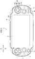
- FIG. 1 is a front view of an electronic device 1 according to an embodiment of the invention.
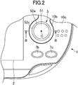
- FIG. 2 is an enlarged front view of the electronic device 1, in which an operation stick 5 on the right side described later is enlarged.
- FIG. 3 is a cross-sectional view taken along the line III-III shown in FIG. 2 .
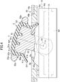
- FIG. 4 is a cross-sectional view showing a state where the operation stick 5 is tilted.
- the direction shown as X1-X2 of FIG. 1 is the right-left direction
- the direction shown as Y1-Y2 is the up-down direction.
- the electronic device 1 is a portable electronic device such as a game machine or a personal information terminal (PDA) and has an audio reproduction function, a video reproduction function, or a wired or wireless communication function. As shown in FIG. 1 , the electronic device 1 has a substantially rectangular display screen 2 on the front surface. The display screen 2 is disposed substantially at the center portion on the front surface. The electronic device 1 has holding portions 1R and 1L that can be held by a user with hands, on the right and the left of the display screen 2. As a form of use of the electronic device 1, a user holds the electronic device 1 by grasping the holding portions 1R and 1L between thumbs, middle fingers, and the like.
- the holding portions 1R and 1L are provided with a plurality of operation members which protrude from the front surface of the housing 10 of the electronic device 1 and can be operated by a user.
- the electronic device 1 has operation sticks 5 positioned on the right and the left of the display screen 2.
- the operation stick 5 protrudes from the front surface of the housing 10.
- the operation stick 5 has an operated portion 54 formed into a substantially discoid shape at the head part.
- the operated portion 54 is a part pressed by the finger of a user when the operation stick 5 is operated by the user.
- the operation stick 5 has a bar-shaped part (hereinafter, a column portion) 53 extending toward the inside of the housing 10 from the operated portion 54 (specifically, a base portion 52 described later).
- the diameter of the column portion 53 is smaller than that of the operated portion 54.
- the operation stick 5 can be moved in the radial direction about the center line C of the column portion 53.
- the operation stick 3 can be tilted in the radial direction (see FIG. 4 ).
- a user presses the outer peripheral edge (an outer peripheral edge 52c (see FIG. 3 ) of a frame portion 52a described later) of the operated portion 54 of the operation stick 5 with a finger to tilt the operation stick 5.
- the user while a user presses the surface (a pressed surface 51a (see FIG. 3 ) described later) of the operation stick 5 with a finger, the user moves the finger in the radial direction (for example, in the up-down direction) to tilt the operation stick 5.
- the movement of the operation stick 5 is not limited to this.
- the operation stick 5 may be enabled to slide in the radial direction without being tilted.
- the electronic device 1 includes a case 6.
- the case 6 in this example is a thin rectangular solid.
- the case 6 accommodates a mechanism A for supporting the base portion of the column portion 53 therein so that the operation stick 5 is moved in the radial direction of the column portion 53.
- the supporting mechanism A in this example includes two shafts 61 and 62 orthogonal to each other.
- the shafts 61 and 62 are supported to be rotatable around their axial lines O1 and 02.
- the shaft 62 is supported by the case 6, and the shaft 61 is supported by the shaft 62.
- the base portion of the column portion 53 is connected to the shaft 61 to be rotatable around the shaft 61.
- the column portion 53 can be tilted in all radial directions of the column portion 53 including the up-down direction, the right-left direction, and the like.
- the case 6 also accommodates a sensor (not shown) for detecting a degree of inclination and a direction of inclination of the column portion 53, that is, angles of rotation of the shafts 61 and 62.
- the angle of rotation detected by the sensor is output to a control circuit such as a CPU included in the electronic device 1.
- the operation stick 5 is, for example, an analog stick, and the sensor outputs a signal representing the angle of rotation.
- a circular opening 6a is formed in the case 6.
- the column portion 53 extends outward from the case 6 through the opening 6a.
- the column portion 53 may be tilted to touch the inner edge of the opening 6a (see FIG. 4 ). That is, the inner edge of the opening 6a functions as a stopper that defines the movable range of the operation stick 5.
- the electronic device 1 accommodates various components such as a circuit board (not shown) and is provided with the housing 10 that forms the outer surface of the electronic device 1.
- the case 6 is also accommodated in the housing 10.
- a circular opening 10a which is larger than the opening 6a is formed in the housing 10.
- the operation stick 5 protrudes toward the outside of the housing 10 from the opening 10a.
- the case 6 is larger than the opening 10a.
- the case 6 is fixed to the housing 10 by, for example, screws.
- the housing 10 in this example includes, as shown in FIGS. 2 and 3 , a housing body 10b that functions as a frame to which the circuit board or the case 6 is mounted, and a front panel 10c that is attached on the surface of the housing body 10b and forms the front surface of the electronic device 1.
- the operation stick 5 includes the operated portion 54 at the tip end portion of the column portion 53.
- the operated portion 54 includes a cushion portion 51 that forms the surface of the operated portion 54, and a base portion 52 which is formed integrally with the tip end portion of the column portion 53 and on which the cushion portion 51 is placed.
- the cushion portion 51 and the base portion 52 in this example are circular in a plan view and have a discoid shape on the whole.
- the cushion portion 51 is formed of a material having cushioning properties, that is, a soft material.
- the material of the cushion portion 51 has soft properties that allow the outer shape of the cushion portion 51 to widen out when the pressed surface 51a is pressed. In other words, in a assumed case where the cushion portion 51 not being surrounded by the frame portion 52a described later is pressed by a user, the outer shape of the cushion portion 51 may widen out.
- the cushion portion 51 may be formed of a material having elasticity.
- the material of the cushion portion 51 is, for example, elastomer such as silicone or rubber.
- the base portion 52 has rigidity so as to suppress the outer shape of the cushion portion 51 from widening out.
- the cushion portion 51 is disposed on the base portion 52 as described above. Therefore, even in a case where the outside diameter of the operated portion 54 is designed small, the cushion portion 51 can ensure a sufficient thickness.
- the pressed surface 51a is curved such that the center thereof is swollen up. Therefore, when a user operates the operation stick 5, the finger of the user easily touches the cushion portion 51, so that a good touch feeling is easily obtained.
- the bottom surface of the base portion 52 on which the cushion portion 51 is disposed is also curved such that the center thereof is swollen up in conformity with the pressed surface 51a.
- the cushion portion 51 has substantially the same thickness over the entire region.
- the base portion 52 has, in the outer periphery, the frame portion 52a surrounding the outer periphery of the cushion portion 51.
- the base portion 52 has a recessed portion formed on the inside of the frame portion 52a, and the cushion portion 51 is disposed inside the recessed portion.
- the base portion 52 and the column portion 53 are formed of a material having a higher rigidity than that of the cushion portion 51.
- the material of the base portion 52, that is, the column portion 53 is plastic such as polycarbonate or an ABS resin (in other words, an engineering plastic). Therefore, even when a user presses the frame portion 52a, a change in the outer shape of the frame portion 52a is suppressed. As a result, when the user presses the outer peripheral edge of the operated portion 54, that is, the outer peripheral edge 52c of the frame portion 52a with a finger, the movement of the finger is clearly transmitted to the sensor in the case 6 through the operation stick 5 and the supporting mechanism A. As described above, the operation stick 5 is an analog stick, and therefore users are required to perform a delicate operation. Because the frame portion 52a is formed of the material having a higher rigidity than that of the cushion portion 51, a delicate operation by users can be clearly detected by the sensor in the electronic device 1.
- the inner surface of the frame portion 52a is contact with the outer peripheral edge of the cushion portion 51.
- the frame portion 52a is formed along the entire periphery of the cushion portion 51 as shown in FIG. 2 .
- the frame portion 52a is formed into an annular shape according to the outer shape of the cushion portion 51. Therefore, even in a case where a user presses any position of the outer peripheral edge of the frame portion 52a with a finger, the movement of the finger is clearly transmitted to the supporting mechanism A.
- the frame portion 52a has a front surface 52b that forms the surface of the operated portion 54 together with the pressed surface 51a.
- a slight level difference is formed between the outer peripheral edge of the pressed surface 51a and the front surface 52b, and the front surface 52b is positioned at a slightly lower position than the outer peripheral edge of the pressed surface 51a. Therefore, when a user presses the pressed surface 51a, the outer peripheral edge of the pressed surface 51a can slightly widen out. As a result, the cushioning properties of the cushion portion 51 can be increased.
- the front surface 52b may also be flush with the outer peripheral edge of the pressed surface 51a. In this structure, even when the finger of a user touches both the front surface 52b and the outer peripheral edge of the pressed surface 51a, a good touch feeling can be obtained.
- FIG. 5 is a plan view of the base portion 52. As shown in FIGS. 3 and 5 , through-holes 52d and 52e and a hole (recessed portion) 52f are formed in the base portion 52.
- the cushion portion 51 has protrusions 51c and 51i fitted into the holes 52d, 52e, and 52f. As such, the holes 52d, 52e, and 52f are formed in the base portion 52 other than in the cushion portion 51, so that the thickness of the cushion portion 51 can be ensured over the entire region thereof. As a result, no matter which part of the pressed surface 51a the finger of a user touches, a good touch feeling can be obtained.
- a plurality of the through-holes 52d and 52e are annularly disposed to surround the center line C of the column portion 53 at intervals.
- the protrusions 51c fitted into the holes 52d and 52e are annularly disposed. Therefore, even in a case where the operation stick 5 is moved in any direction, the deviation of the relative positions of the cushion portion 51 and the base portion 52 can be suppressed.
- the holes 52f formed in the base portion 52 are disposed inside the through-holes 52d and 52e and are annularly disposed to surround the center line C.
- the projection 51c has, at the end portion thereof, an engagement portion 51d having a larger width than a width W1 of the through-holes 52d and 52e.
- the engagement portion 51d is caught on the rear surface of the base portion 52. Accordingly, disengagement of the protrusion 51c from the base portion 52 is suppressed.
- the protrusion 51c and the engagement portion 51d are formed at the outer peripheral portions of the cushion portion 51. More specifically, the protrusion 51c protrudes downward from the outer peripheral edge of the cushion portion 51. Therefore, the outer peripheral edge of the cushion portion 51 is suppressed from separating from the base portion 52 or the frame portion 52a.
- the engagement portion 51d in this example is formed into an annular shape surrounding the center line C. That is, the end portions of the protrusions 51c are connected to each other to form the annular engagement portion 51d. Therefore, even though a force is exerted on any position of the outer peripheral edge of the cushion portion 51, the cushion portion 51 is suppressed from separating from the base portion 52 or the frame portion 52a.
- the opening 6a of the case 6 described above has an inside diameter which is larger than the diameter of the column portion 53 so as to allow a tilt of the column portion 53. Therefore, a gap is formed around the column portion 53.
- the operation stick 5 has a cover portion 51e that widens in the radial direction of the column portion 53 and is positioned toward the opening 6a from the operated portion 54.
- the cover portion 51e covers the gap between the column portion 53 and the inner edge of the opening 6a. That is, the cover portion 51e is positioned on the outside of the opening 6a and has an outside diameter that is larger than the diameter of the opening 6a.
- the cover portion 51e in this example has substantially the same outside diameter as that of the operated portion 54.
- the operation stick 5 has, between the cover portion 51e and the operated portion 54, a portion E with a smaller diameter than them.
- the outside diameter of the cover portion 51e is larger than the inside diameter of the opening 6a of the case 6. That is, the outer peripheral edge 51f of the cover portion 51e is positioned further outwardly in the radial direction than the edge of the opening 6a.
- the cover portion 51e covers the opening 6a. That is, when the operation stick 5 is tilted to one side (for example, the right), a part of the cover portion 51e on the opposite side (for example, the left) overlaps the edge of the opening 6a.
- the outside diameter of the cover portion 51e is designed so that, even when the operation stick 5 is tilted to the limit, the outer peripheral edge 51f of the cover portion 51e is positioned further outwardly in the radial direction than the edge of the opening 6a.
- the outside diameter of the cover portion 51e is smaller than the inside diameter of the opening 10a of the housing 10.
- the outer peripheral edge 51f of the cover portion 51e is positioned further inwardly than the edge of the opening 10a.
- the cross-section of the cover portion 51e has an arc shape which becomes close to the case 6 as it goes to the outer periphery of the cover portion 51e (the cross-section here uses, as its cutting surface, a surface passing through the center line C of the column portion 53). That is, the cover portion 51e has an umbrella shape, and extends downward toward the outer periphery.
- the case 6 includes a swollen portion 6b swollen toward the inside of the cover portion 51e.
- the opening portion 6a is formed at the apex portion of the swollen portion 6b.
- the swollen portion 6b is positioned on the inside of the opening 10a of the housing 10. Specifically, the swollen portion 6b overlaps the housing 10 in the horizontal direction.
- the body 6d of the case 6 can be disposed to be close to an inner surface 10d of the housing 10 (here, the inner surface 10d is a surface facing the body 6d).
- the cover portion 51e is positioned toward the outside of the housing 10 than the inner surface 10d of the housing 10. That is, the cover portion 51e is distant from a plane P1 including the inner surface 10d toward the outside of the housing 10.
- the outer peripheral edge 51f of the cover portion 51e can be suppressed from intruding into a gap K between the inner surface 10d of the housing 10 and the case 6.
- the gap K can be reduced, so that a reduction in the thickness of the electronic device 1 can be achieved.
- the outer peripheral edge 51f of the cover portion 51 is distant from the plane P1 toward the outside of the housing 10, and the entirety of the cover portion 51e is disposed toward the outside than the inner surface 10d.
- most of the cover portion 51e may be positioned toward the outside from the plane P1, and the outer peripheral edge 51f of the cover portion 51e may be positioned inwardly from the plane P1.
- the outer peripheral edge 51f of the cover portion 51e is positioned toward the inside of the housing 10 from a plane P2 including the outer surface of the housing 10, and is positioned toward the inside of the housing 10 than the edge of the opening 6a of the case 6.
- the size of the cover portion 51e is designed so that, even when the operation stick 5 is tilted to the limit, the outer peripheral edge 51f does not come into contact with the body 6d of the case 6 or the edge of the housing 10a of the housing 10.
- the cover portion 51e is formed of a flexible material.
- the cover portion 51e is formed of elastomer such as silicone or rubber.
- the material of the cover portion 51e uses such a material, compared to a structure in which the cover portion 51e is formed of a hard material such as plastic, a clearance for preventing the interference between the case 6 or the edge of the opening 10a of the housing 10, and the outer peripheral edge 51f of the cover portion 51e can be reduced. As a result, it becomes easy to increase the size of the cover portion 51e.
- the cushion portion 51 is formed of the same material as the cover portion 51e. Consequently, the number of processes for molding the operation stick 5 can be reduced.
- the operation stick 5 may be molded by two-color molding (that is, double molding). That is, after the base portion 52 and the column portion 53 are formed by primary molding, they are put into a mold (a mold corresponding to the outer shape of the operation stick 5) for secondary molding. The materials of the cushion portion 51 and the cover portion 51e are poured into the mold. Accordingly, the cushion portion 51 and the cover portion 51e which are integrated with the base portion 52 and the column portion 53 are molded.
- the plurality of through-holes 52d and 52e are formed in the bottom of the base portion 52.
- the cover portion 51e and the cushion portion 51 are connected to each other through the through-holes 52d and 52e.
- the engagement portion 51d is formed at the lower ends of the protrusions 51c fitted into the through-holes 52d and 52e.
- An inner peripheral edge (upper edge) 51h of the cover portion 51e is connected to the engagement portion 51d.
- the engagement portion 51d prevents both the cushion portion 51 and the cover portion 51e from being separated from the base portion 52 and the column portion 53.
- the cushion portion 51 and the cover portion 51e are connected using the through-holes 52d and 52e, compared to a structure in which the entirety of the operated portion 54 is enfolded by a material forming the cushion portion 51, the material can be more effectively suppressed from being removed from the operated portion 54.
- the cover portion 51e widens in the radial direction from the upper portion of the column portion 53.
- the column portion 53 includes, in the upper portion, a large diameter portion 53a which has a larger diameter than that of the base portion or the intermediate portion (a part positioned on the inside of the inner periphery of the opening 6a) of the column portion 53.
- the cover portion 51e widens from the outer peripheral surface of the large diameter portion 53a in the radial direction. This structure enables the cover portion 51e having a small width W2 to cover the opening portion 6a of the case 6.
- the supporting mechanism A in the case 6 is suppressed from being exposed.
- the cover portion 51e widens from the lower edge of the large diameter portion 53a in the radial direction. Accordingly, the gap between the cover portion 51e and the swollen portion 6b can be reduced.
- the engagement portion 51d described above is annular, and a part between the upper edge 51h of the cover portion 51e and the engagement portion 51d is tubular. The tubular portion surrounds the outer periphery of the large diameter portion 53a.
- the holding portion 1R on the right is provided with a button group 4R.
- the button group 4R includes a plurality of (specifically, four) buttons 4a, 4b, 4c, and 4d.
- the buttons 4a, 4b, 4c, and 4d are provided at end portions of a cross.
- the holding portion 1L on the left is provided with a direction key 4L.
- the direction key 4L has a plurality of (specifically, four) convex portions formed into a cross shape on the whole.
- the button group 4R and the direction key 4L are respectively positioned on the upper sides of the operation sticks 5 on the left and the right. In addition, the button group 4R and the direction key 4L are positioned further outwardly in the right-left direction than the operation sticks 5.
- users dispose the thumbs on the operation sticks 5 and dispose the middle fingers or the like on the rear surface (the rear surfaces of the holding portions 1R and 1L) of the electronic device 1 to hold the holding portions 1R and 1L.
- users obliquely move the thumbs toward the button group 4R or the direction key 4L as needed.
- buttons 7a, 7b, and 7c are further provided.
- the button 7a is, for example, a home button used for returning an image displayed on the display screen 2 to an initial image.
- the buttons 7b and 7c are, for example, a select button used for selecting an item displayed on the display screen 2, a start button for instructing a start of execution of an application software, and the like.
- the surfaces of the buttons 7a, 7b, and 7c are flush with the front surface of the housing 10, that is, the front panel 10c (see FIG. 3 ).
- FIG. 6 is a cross-sectional view of an operation stick 3 in this example, and a cutting surface thereof is aligned with the line III-III shown in FIG. 2 .
- the method of operating the operation stick 3 or the operation thereof is the same as that of the operation stick 5 described above.
- the operation stick 3 includes an operated portion 34 at the head portion as shown in FIG. 6 .
- the operated portion 34 includes a cushion portion 31 and a base portion 32 on which the cushion portion 31 is placed.
- the structures of the cushion portion 31 and the base portion 32 are substantially the same as those of the cushion portion 51 and the base portion 52 described above. Hereinafter, detailed description will be provided.
- the cushion portion 31 is formed of a soft material, like the cushion portion 51. Therefore, when a user presses a pressed surface 31a of the cushion portion 31, the pressed surface 31a deforms according to the shape of the finger, so that the user can obtain a good touch feeling.
- the cushion portion 31 is disposed on the base portion 32. Therefore, even in a case where the outside diameter of the upper portion of the operation stick 3 including the cushion portion 31 and the base portion 32 needs to be small, the cushion portion 31 can be designed to have a sufficient thickness.
- the pressed surface 31a is curved such that the center thereof is swollen up.
- the thickness of the cushion portion 31 is maximized at a part of the pressed surface 31a on which a force is most likely to be exerted from the finger of the user (that is, the center of the pressed surface 31a). Accordingly, the user can obtain a better touch feeling.
- the cushion portion 31 has a thickness greater than that of the base portion 32. Accordingly, the thickness of the cushion portion 31 can be ensured while suppressing an increase in the thickness of the whole of the operated portion 34.
- the thickness of the center portion of the cushion portion 31 is greater than the thickness D2 of the base portion 32.
- the thickness D1 of the outermost portion of the cushion portion 31 is substantially the same as the thickness D2 of the base portion 32.
- the thickness D1 of the outermost portion of the cushion portion 31 may be greater than the thickness D2 of the base portion 32.
- the thickness D1 of the outermost portion of the cushion portion 31 may be smaller than the thickness D2 of the base portion 32.
- the base portion 32 may be moved in the radial direction about the center line C of the operation stick 3 (for example, in the up-down direction or the right-left direction).
- the operation stick 3 in this example has a column portion 33 extending toward the inside of the electronic device 1 from the base portion 32, like the operation stick 5.
- the base portion of the column portion 33 is supported by a supporting mechanism A included in the case 6 described above and can be tilted in all directions about the center line C.
- the base portion 32 also has a frame portion 32a, like the base portion 52.
- the base portion 32 is formed of a material having a higher rigidity than the material of the cushion portion 31, like the base portion 52. That is, the material of the base portion 32 is plastic such as polycarbonate or an ABS resin (in other words, an engineering plastic). Therefore, when a user presses an outer peripheral edge 32c of the frame portion 32a with the finger, the movement of the finger is clearly transmitted to a sensor of the supporting mechanism A through the operation stick 3.
- the frame portion 32a is formed over the entire periphery of the cushion portion 31, like the frame portion 52a.
- the operation stick 3 in this example is also formed by two-color molding (double molding), like the operation stick 5.
- the frame portion 32a has a front surface 32b which forms the surface of the operated portion 34 together with the pressed surface 31a.
- the front surface 32b and the outer peripheral portion of the pressed surface 31a form the same plane. In other words, the front surface 32b is flush with the outer peripheral portion of the pressed surface 31a.
- the outer peripheral portion of the pressed surface 31a is inclined such that the outer edge thereof descends.
- the front surface 32b is inclined in conformity with the outer peripheral portion of the pressed surface 31a such that its outer peripheral edge descends, and thus is continuously connected to the pressed surface 31a. That is, a gap between the front surface 32b and the pressed surface 31a is not formed.
- the relationship between the front surface 32b and the pressed surface 31a is not limited to this.
- a slight gap between the front surface 32b and the outer peripheral edge of the pressed surface 31a may be formed.
- the pressed surface 31a may be formed to be horizontal. In this case, the entirety of the pressed surface 31a and the front surface 32b of the frame portion 32a may form the same plane.
- a plurality of through-holes 32d are formed in the base portion 32.
- the cushion portion 31 has a plurality of protrusions 31c fitted into the through-holes 32d.
- the plurality of through-holes 32d and the plurality of protrusions 31c are disposed in an annular shape surrounding the center line C, like the through-holes 52d and 52e and the protrusions 51c described above.
- the protrusion 31c reaches the opposite side to the cushion portion 31 of the base portion 32 through the through-hole 32d. That is, the protrusion 31c penetrates through the base portion 32 in the thickness direction.
- the protrusion 31c includes an engagement portion 31d at the end portion.
- the engagement portion 31d is positioned on the rear side of the base portion 32 and has a width greater than the width W3 of the hole formed in the base portion 32. Accordingly, the engagement portion 31d is caught on the rear surface of the base portion 32.
- the engagement portion 31d is annular and surrounds the column portion 33. That is, the end portions of the protrusions 31c are connected to each other to form the annular engagement portion 31d. Therefore, the cushion portion 31 is much less likely to come off the base portion 32.
- the inside diameter of the engagement portion 31d corresponds to the outside diameter of the column portion 33.
- the protrusions 31c and the engagement portion 31d are positioned toward on the outer side of the cushion portion 31. Specifically, the distance R1 between the protrusion 31c and the outer edge of the cushion portion 31 is smaller than the distance between the protrusion 31c and the center line C. Therefore, the outer edge of the cushion portion 31 is more effectively suppressed from separating from the base portion 32.
- the operation sticks 3 and 5 include the cushion portions 31 and 51 having the pressed surfaces 31a and 51a on the surfaces thereof, and the base portions 32 and 52 on which the cushion portions 31 and 51 are placed and which are supported to be movable.
- the base portions 32 and 52 have the frame portions 32a and 52a surrounding the outer peripheries of the cushion portions 31 and 51 and are formed of materials having higher rigidities than those of the cushion portions 31 and 51. Therefore, even when materials with high cushioning properties are used for the cushion portions 31 and 51, changes in the outer shapes of the operated portions 34 and 54 of the operation sticks 3 and 5 are suppressed. As a result, the movement of the finger operating the operation sticks 3 and 5 can be clearly transmitted to the electronic device 1, so that degradation in operability can be suppressed.
- the cushion portions 31 and 51 are disposed on the base portions 32 and 52, even in the case where the sizes of the operated portions 34 and 54 of the operation sticks 3 and 5 are reduced, it becomes easy to maintain the thicknesses of the cushion portions 31 and 51.
- the operation sticks 3 and 5 include the column portions 33 and 53 with a tip end on which the base portions 32 and 52 formed, and the column portions 33 and 53 are movable. Therefore, when a user presses the outer peripheral edges of the frame portions 32a and 52a with a finger to tilt or slide the operation sticks 3 and 5, the movement of the finger is clearly input to the electronic device 1 through the operation sticks 3 and 5.
- the frame portions 32a and 52a are formed over the entire peripheries of the cushion portions 31 and 51. Consequently, when the operation sticks 3 and 5 are moved in any radial direction, the movement of the finger can be clearly input to the electronic device.
- the thickness of the cushion portion 31 is greater than the thickness of the base portion 32. Accordingly, the thickness of the cushion portion 31 can be easily ensured.
- the cushion portions 31 and 51 are provided with the protrusions 31c, 51c, and 51i protruding toward the base portions 32 and 52, and the base portions 32 and 52 have the holes 32d, 52f, and 52d formed thereon into which the protrusions 31c, 51c, and 51i are fitted.
- the base portions 32 and 52 may be provided with protrusions protruding toward the cushion portions 31 and 51, and the cushion portions 31 and 51 may have holes into which the protrusions of the base portions 32 and 52 are fitted.
- the protrusions 31c, 51c, and 51i are arranged in an annular shape surrounding the center line of the column portions 32 and 52. Accordingly, the deviation of the relative positions of the cushion portions 31 and 51 and the base portions 32 and 52 can be effectively suppressed.
- the holes 32d and 52d of the base portions 32 and 52 penetrate through the base portions 32 and 52, and the protrusions 31c and 51c of the cushion portions 31 and 51 reach the opposite sides of the base portions 32 and 52 through the holes 32d and 52d, and have, at the end portions, the engagement portions 31d and 51d caught on the base portions 32 and 52. Accordingly, the cushion portions 31 and 51 can be suppressed from separating from the base portions 32 and 52.
- the cushion portions 31 and 51 are provided with the plurality of protrusions 31c and 51c and they are arranged in an annular shape surrounding the column portions 33 and 53.
- the engagement portions 31d and 51d formed at the end portions thereof are formed into annular shapes. Accordingly, even in a case where the operation sticks are moved in any direction, the cushion portions 31 and 51 are effectively suppressed from coming off the base portions 32 and 52.
- the frame portion 32a includes an outer surface which forms the same plane together with the outer peripheral portion of the surface of the cushion portion 31.
- the materials of the cushion portions 31 and 51 have soft properties such that the outer shapes thereof widen out when the surfaces of the cushion portions 31 and 51 is pressed.
- the cushion portions 31 and 51 have such a degree of soft properties, a better touch feeling can be obtained when a user operates the operation sticks 3 and 5.
- the operation stick 5 includes the cover portion 51e. Accordingly, the mechanism in the case 6 can be hidden from view, and infiltration of dust or the like into the case 6 can be prevented by the cover portion 51e.
- the cover portion 51e is positioned toward the outside of the housing 10 than the inner surface 10d of the housing 10.
- the case 6 can be disposed closer to the inner surface 10d of the housing 10. Therefore, a reduction in the thickness and a reduction in the size of the electronic device 1 can be achieved.
- the outer peripheral edge 51f of the cover portion 51e is positioned further outwardly in the radial direction than the edge of the opening 6a of the case 6, and is positioned further inwardly in the radial direction than the edge of the opening 10a of the housing 10.
- the cover 51e is connected to the cushion portion 51.
- the cover portion 51e is connected through the through-hole 52d formed in the base portion 52. Accordingly, the cover portion 51e can be firmly fixed to the column portion 53 and the base portion 52.
- the cover portion 51e is formed of a flexible material. Accordingly, compared to a structure in which the cover portion 51e is formed of a hard material such as plastic, the clearance for preventing the interference between the case 6 or the edge of the opening 10a of the housing 10, and the outer peripheral edge 51f of the cover portion 51e can be reduced. As a result, it becomes easy to increase the size of the cover portion 51e, so that the function of the cover portion 51e can be enhanced.
- the material of the cover portion 51e is the same as the material of the cushion portion 51. Therefore, the number of processes for molding the operation stick 5 can be reduced.
- the case 6 has the opening 6a formed thereon and the swollen portion 6b swollen toward the inside of the cover portion 51e.
- the large diameter portion 53a may not necessarily be provided in the column portion 53.
- the cover portion 51e may widen in the radial direction from a part having the same thickness as that of the base portion of the column portion 53.
- the case 6 may not necessarily be provided with the swollen portion 6b.
- the main body 6d of the case 6 may have the opening 6a.
- the cover portion 51e and the cushion portion 51 may not necessarily be connected to each other.
- the cover portion 51e and the cushion portion 51 may be respectively fixed to the column portion 53 and the base portion 52.
- the cushion portion 51 may be adhered to the base portion 52, and the cover portion 51e may be adhered to the column portion 53.
- the protrusion 51c and the engagement portion 51d may not be provided in the cushion portion 51.
- the cushion portion 31 may be adhered to the base portion 32. In this case, the protrusion 31c and the engagement portion 31d may not be provided in the cushion portion 31.
- buttons 4a, 4b, 4c, and 4d constituting the button group 4R and the direction key 4L may include the cushion portions 31 and 51 and the base portions 32 and 52 described above.
- the frame portions 32a and 52a are disposed in the outer peripheries of the cushion portions 31 and 51, the finger of the user may touch the frame portions 32a and 52a as well as the cushion portions 31 and 51. As a result, pressing of the direction key 4L and the buttons 4a, 4b, 4c, and 4d can be clearly transmitted to the electronic device.
- a film made of a different material from the cushion portion 31 may be adhered to the surface of the cushion portion 31. Accordingly, smoothness of the surface of the cushion portion 31 can be enhanced or a non-slip function of the surface of the cushion portion 31 can be enhanced.
Landscapes
- Engineering & Computer Science (AREA)
- Theoretical Computer Science (AREA)
- General Engineering & Computer Science (AREA)
- Physics & Mathematics (AREA)
- General Physics & Mathematics (AREA)
- Human Computer Interaction (AREA)
- Multimedia (AREA)
- Computer Hardware Design (AREA)
- Automation & Control Theory (AREA)
- Switches With Compound Operations (AREA)
- Position Input By Displaying (AREA)
- Casings For Electric Apparatus (AREA)
Abstract
Description
- The present invention relates to an operation member provided in an electronic device, such as (though not exclusively) a pushbutton or an operation stick.
- An electronic device such as a portable game machine or a controller of a game device includes an operation member that is operated by a user with a finger, such as a pushbutton or an operation stick. In the specification of
U.S. Patent No. 6394906 , an operation stick provided in a controller is disclosed. The operation stick has a column portion, and the upper end of the column portion is formed into a discoid shape. The entirety of the outer surface of the discoid part is covered with a cover. The cover enfolds the upper end of the column portion. The cover is formed of a softer material (elastomer in PatentU.S. Patent No. 6394906 ) than that of the column portion. Accordingly, an improvement in a touch feeling obtained when a user touches the operation stick is achieved. - However, when the outside diameter of the operation stick is designed small in the structure where the cover enfolds the upper end of the column portion, there is a need to reduce the thickness of the cover. Therefore, it becomes difficult to maintain the thickness of the cover, that is, cushioning properties. In addition, when a material with higher cushioning properties is used for the cover in the structure in which the cover enfolds the upper end of the column portion, it becomes difficult to clearly transmit a movement of the finger operating the operation stick to the electronic device, resulting in a reduction in operability.
- Various respective aspects and features of the invention are defined in the appended claims. Combinations of features from the dependent claims may be combined with features of the independent claims as appropriate and not merely as explicitly set out in the claims.
- An operation member according to an aspect of the invention can be operated by a user with a finger. The operation member includes: a cushion portion including, on a surface thereof, a pressed surface that is pressed by the finger of the user; and a base portion on which the cushion portion is placed and which is supported to be movable; and a frame portion formed in the base portion to surround an outer periphery of the cushion portion. The frame portion and the base portion are formed of a material having a higher rigidity than that of the cushion portion.
- In addition, an electronic device according to another aspect of the invention includes the operation member.
- According to the aspects of the invention, because the operation member has the frame portion surrounding the outer periphery of the cushion portion, even in the case where a material having high cushioning properties is used for the cushion portion, the movement of the finger operating the operation member can be clearly transmitted to the electronic device, thereby suppressing deterioration in operability. In addition, because the cushion portion is disposed on the base portion, even when the operation member is reduced in size, it becomes easy to maintain the thickness of the cushion portion.
- Embodiments of the invention will now be described with reference to the accompanying drawings, throughout which like parts are referred to by like references, and in which:
-
FIG. 1 is a front view of an electronic device according to an embodiment of the invention. -
FIG. 2 is an enlarged front view of the electronic device, in which an operation stick on the right side is enlarged. -
FIG. 3 is a cross-sectional view taken along the line III-III shown inFIG. 2 . -
FIG. 4 is a cross-sectional view showing a state where the operation stick is tilted. -
FIG. 5 is a plan view of a base portion included in the operation stick. -
FIG. 6 is a cross-sectional view of another example of the operation stick. - Hereinafter, an embodiment of the invention will be described with reference to the drawings.
FIG. 1 is a front view of an electronic device 1 according to an embodiment of the invention.FIG. 2 is an enlarged front view of the electronic device 1, in which an operation stick 5 on the right side described later is enlarged.FIG. 3 is a cross-sectional view taken along the line III-III shown inFIG. 2 .FIG. 4 is a cross-sectional view showing a state where theoperation stick 5 is tilted. In the following description, the direction shown as X1-X2 ofFIG. 1 is the right-left direction, and the direction shown as Y1-Y2 is the up-down direction. - The electronic device 1 is a portable electronic device such as a game machine or a personal information terminal (PDA) and has an audio reproduction function, a video reproduction function, or a wired or wireless communication function. As shown in
FIG. 1 , the electronic device 1 has a substantiallyrectangular display screen 2 on the front surface. Thedisplay screen 2 is disposed substantially at the center portion on the front surface. The electronic device 1 has holdingportions display screen 2. As a form of use of the electronic device 1, a user holds the electronic device 1 by grasping theholding portions - As shown in
FIG. 1 , theholding portions housing 10 of the electronic device 1 and can be operated by a user. Specifically, the electronic device 1 hasoperation sticks 5 positioned on the right and the left of thedisplay screen 2. The operation stick 5 protrudes from the front surface of thehousing 10. As shown inFIG. 3 , theoperation stick 5 has an operatedportion 54 formed into a substantially discoid shape at the head part. The operatedportion 54 is a part pressed by the finger of a user when theoperation stick 5 is operated by the user. Theoperation stick 5 has a bar-shaped part (hereinafter, a column portion) 53 extending toward the inside of thehousing 10 from the operated portion 54 (specifically, abase portion 52 described later). The diameter of thecolumn portion 53 is smaller than that of the operatedportion 54. Theoperation stick 5 can be moved in the radial direction about the center line C of thecolumn portion 53. In this example, theoperation stick 3 can be tilted in the radial direction (seeFIG. 4 ). - As a form of the operation, a user presses the outer peripheral edge (an outer
peripheral edge 52c (seeFIG. 3 ) of aframe portion 52a described later) of the operatedportion 54 of theoperation stick 5 with a finger to tilt theoperation stick 5. In addition, as another form of the operation, while a user presses the surface (a pressedsurface 51a (seeFIG. 3 ) described later) of theoperation stick 5 with a finger, the user moves the finger in the radial direction (for example, in the up-down direction) to tilt theoperation stick 5. The movement of theoperation stick 5 is not limited to this. For example, theoperation stick 5 may be enabled to slide in the radial direction without being tilted. - As shown in
FIG. 3 , the electronic device 1 includes acase 6. Thecase 6 in this example is a thin rectangular solid. Thecase 6 accommodates a mechanism A for supporting the base portion of thecolumn portion 53 therein so that theoperation stick 5 is moved in the radial direction of thecolumn portion 53. The supporting mechanism A in this example includes twoshafts shafts shaft 62 is supported by thecase 6, and theshaft 61 is supported by theshaft 62. The base portion of thecolumn portion 53 is connected to theshaft 61 to be rotatable around theshaft 61. By this structure, thecolumn portion 53 can be tilted in all radial directions of thecolumn portion 53 including the up-down direction, the right-left direction, and the like. In addition, thecase 6 also accommodates a sensor (not shown) for detecting a degree of inclination and a direction of inclination of thecolumn portion 53, that is, angles of rotation of theshafts operation stick 5 is, for example, an analog stick, and the sensor outputs a signal representing the angle of rotation. - As shown in
FIG. 3 , acircular opening 6a is formed in thecase 6. Thecolumn portion 53 extends outward from thecase 6 through the opening 6a. In this example, thecolumn portion 53 may be tilted to touch the inner edge of the opening 6a (seeFIG. 4 ). That is, the inner edge of the opening 6a functions as a stopper that defines the movable range of theoperation stick 5. - The electronic device 1 accommodates various components such as a circuit board (not shown) and is provided with the
housing 10 that forms the outer surface of the electronic device 1. As shown inFIG. 3 , thecase 6 is also accommodated in thehousing 10. Acircular opening 10a which is larger than theopening 6a is formed in thehousing 10. Theoperation stick 5 protrudes toward the outside of thehousing 10 from theopening 10a. In addition, thecase 6 is larger than theopening 10a. Thecase 6 is fixed to thehousing 10 by, for example, screws. Moreover, thehousing 10 in this example includes, as shown inFIGS. 2 and3 , ahousing body 10b that functions as a frame to which the circuit board or thecase 6 is mounted, and afront panel 10c that is attached on the surface of thehousing body 10b and forms the front surface of the electronic device 1. - As described above, the
operation stick 5 includes the operatedportion 54 at the tip end portion of thecolumn portion 53. As shown inFIG. 3 , the operatedportion 54 includes acushion portion 51 that forms the surface of the operatedportion 54, and abase portion 52 which is formed integrally with the tip end portion of thecolumn portion 53 and on which thecushion portion 51 is placed. Thecushion portion 51 and thebase portion 52 in this example are circular in a plan view and have a discoid shape on the whole. - As a form of the operation of the
operation stick 5, a user tilts theoperation stick 5 while pressing thesurface 51a of the cushion portion 51 (hereinafter, thesurface 51a is referred to as apressed surface 51a) . Thecushion portion 51 is formed of a material having cushioning properties, that is, a soft material. The material of thecushion portion 51 has soft properties that allow the outer shape of thecushion portion 51 to widen out when the pressedsurface 51a is pressed. In other words, in a assumed case where thecushion portion 51 not being surrounded by theframe portion 52a described later is pressed by a user, the outer shape of thecushion portion 51 may widen out. Therefore, when the user presses the pressedsurface 51a of thecushion portion 51, the pressedsurface 51a deforms according to the shape of the finger, so that the user can obtain a good touch feeling. Thecushion portion 51 may be formed of a material having elasticity. The material of thecushion portion 51 is, for example, elastomer such as silicone or rubber. Thebase portion 52 has rigidity so as to suppress the outer shape of thecushion portion 51 from widening out. - The
cushion portion 51 is disposed on thebase portion 52 as described above. Therefore, even in a case where the outside diameter of the operatedportion 54 is designed small, thecushion portion 51 can ensure a sufficient thickness. - As shown in
FIG. 3 , the pressedsurface 51a is curved such that the center thereof is swollen up. Therefore, when a user operates theoperation stick 5, the finger of the user easily touches thecushion portion 51, so that a good touch feeling is easily obtained. In addition, the bottom surface of thebase portion 52 on which thecushion portion 51 is disposed is also curved such that the center thereof is swollen up in conformity with the pressedsurface 51a. In addition, thecushion portion 51 has substantially the same thickness over the entire region. By this structure, a portion with excessively high cushioning properties in the pressedsurface 51a can be prevented from generating. - As shown in
FIG. 3 , thebase portion 52 has, in the outer periphery, theframe portion 52a surrounding the outer periphery of thecushion portion 51. In other words, thebase portion 52 has a recessed portion formed on the inside of theframe portion 52a, and thecushion portion 51 is disposed inside the recessed portion. - The
base portion 52 and thecolumn portion 53 are formed of a material having a higher rigidity than that of thecushion portion 51. The material of thebase portion 52, that is, thecolumn portion 53 is plastic such as polycarbonate or an ABS resin (in other words, an engineering plastic). Therefore, even when a user presses theframe portion 52a, a change in the outer shape of theframe portion 52a is suppressed. As a result, when the user presses the outer peripheral edge of the operatedportion 54, that is, the outerperipheral edge 52c of theframe portion 52a with a finger, the movement of the finger is clearly transmitted to the sensor in thecase 6 through theoperation stick 5 and the supporting mechanism A. As described above, theoperation stick 5 is an analog stick, and therefore users are required to perform a delicate operation. Because theframe portion 52a is formed of the material having a higher rigidity than that of thecushion portion 51, a delicate operation by users can be clearly detected by the sensor in the electronic device 1. - The inner surface of the
frame portion 52a is contact with the outer peripheral edge of thecushion portion 51. Theframe portion 52a is formed along the entire periphery of thecushion portion 51 as shown inFIG. 2 . In this example, theframe portion 52a is formed into an annular shape according to the outer shape of thecushion portion 51. Therefore, even in a case where a user presses any position of the outer peripheral edge of theframe portion 52a with a finger, the movement of the finger is clearly transmitted to the supporting mechanism A. - As shown in
FIG. 3 , theframe portion 52a has afront surface 52b that forms the surface of the operatedportion 54 together with the pressedsurface 51a. In this example, a slight level difference is formed between the outer peripheral edge of the pressedsurface 51a and thefront surface 52b, and thefront surface 52b is positioned at a slightly lower position than the outer peripheral edge of the pressedsurface 51a. Therefore, when a user presses the pressedsurface 51a, the outer peripheral edge of the pressedsurface 51a can slightly widen out. As a result, the cushioning properties of thecushion portion 51 can be increased. In this regard, thefront surface 52b may also be flush with the outer peripheral edge of the pressedsurface 51a. In this structure, even when the finger of a user touches both thefront surface 52b and the outer peripheral edge of the pressedsurface 51a, a good touch feeling can be obtained. - One of the
cushion portion 51 and thebase portion 52 is provided with a protrusion fitted into a hole formed in the other. Accordingly, deviation of the relative positions of thecushion portion 51 and thebase portion 52 can be suppressed.FIG. 5 is a plan view of thebase portion 52. As shown inFIGS. 3 and5 , through-holes base portion 52. Thecushion portion 51 hasprotrusions holes holes base portion 52 other than in thecushion portion 51, so that the thickness of thecushion portion 51 can be ensured over the entire region thereof. As a result, no matter which part of the pressedsurface 51a the finger of a user touches, a good touch feeling can be obtained. - As shown in
FIG. 5 , a plurality of the through-holes column portion 53 at intervals. Similarly, theprotrusions 51c fitted into theholes operation stick 5 is moved in any direction, the deviation of the relative positions of thecushion portion 51 and thebase portion 52 can be suppressed. In addition, theholes 52f formed in thebase portion 52 are disposed inside the through-holes cushion portion 51 is prevented from being misaligned from thebase portion 52. - As shown in
FIG. 3 , theprojection 51c has, at the end portion thereof, anengagement portion 51d having a larger width than a width W1 of the through-holes engagement portion 51d is caught on the rear surface of thebase portion 52. Accordingly, disengagement of theprotrusion 51c from thebase portion 52 is suppressed. - The
protrusion 51c and theengagement portion 51d are formed at the outer peripheral portions of thecushion portion 51. More specifically, theprotrusion 51c protrudes downward from the outer peripheral edge of thecushion portion 51. Therefore, the outer peripheral edge of thecushion portion 51 is suppressed from separating from thebase portion 52 or theframe portion 52a. In addition, theengagement portion 51d in this example is formed into an annular shape surrounding the center line C. That is, the end portions of theprotrusions 51c are connected to each other to form theannular engagement portion 51d. Therefore, even though a force is exerted on any position of the outer peripheral edge of thecushion portion 51, thecushion portion 51 is suppressed from separating from thebase portion 52 or theframe portion 52a. - As shown in
FIG. 3 , theopening 6a of thecase 6 described above has an inside diameter which is larger than the diameter of thecolumn portion 53 so as to allow a tilt of thecolumn portion 53. Therefore, a gap is formed around thecolumn portion 53. Theoperation stick 5 has acover portion 51e that widens in the radial direction of thecolumn portion 53 and is positioned toward theopening 6a from the operatedportion 54. Thecover portion 51e covers the gap between thecolumn portion 53 and the inner edge of theopening 6a. That is, thecover portion 51e is positioned on the outside of theopening 6a and has an outside diameter that is larger than the diameter of theopening 6a. By this structure including the cover portion51e, the supporting mechanism A in thecase 6 can be hidden from view, and infiltration of dust or the like into thecase 6 can be prevented. In this regard, thecover portion 51e in this example has substantially the same outside diameter as that of the operatedportion 54. Theoperation stick 5 has, between thecover portion 51e and the operatedportion 54, a portion E with a smaller diameter than them. - The outside diameter of the
cover portion 51e is larger than the inside diameter of theopening 6a of thecase 6. That is, the outerperipheral edge 51f of thecover portion 51e is positioned further outwardly in the radial direction than the edge of theopening 6a. In this example, as shown inFIG. 4 , even when theoperation stick 5 is tilted to the limit, that is, even when thecolumn portion 53 comes into contact with the edge of theopening 6a, thecover portion 51e covers theopening 6a. That is, when theoperation stick 5 is tilted to one side (for example, the right), a part of thecover portion 51e on the opposite side (for example, the left) overlaps the edge of theopening 6a. In conclusion, the outside diameter of thecover portion 51e is designed so that, even when theoperation stick 5 is tilted to the limit, the outerperipheral edge 51f of thecover portion 51e is positioned further outwardly in the radial direction than the edge of theopening 6a. As shown inFIG. 3 , the outside diameter of thecover portion 51e is smaller than the inside diameter of theopening 10a of thehousing 10. In other words, the outerperipheral edge 51f of thecover portion 51e is positioned further inwardly than the edge of theopening 10a. By thecover portion 51e having such a size, interference between the outerperipheral edge 51f of thecover portion 51e and thehousing 10 is easily prevented. In this example, even when theoperation stick 5 is tilted to the limit, the outerperipheral edge 51f of thecover portion 51e is positioned further inwardly than the edge of theopening 10a (seeFIG. 4 ). - As shown in
FIG. 3 , the cross-section of thecover portion 51e has an arc shape which becomes close to thecase 6 as it goes to the outer periphery of thecover portion 51e (the cross-section here uses, as its cutting surface, a surface passing through the center line C of the column portion 53). That is, thecover portion 51e has an umbrella shape, and extends downward toward the outer periphery. By the shape of thecover portion 51e, a gap between the edge of theopening 6a and thecover portion 51e that occurs when theoperation stick 5 is tilted as shown inFIG. 4 can be reduced. - As shown in
FIG. 3 , thecase 6 includes aswollen portion 6b swollen toward the inside of thecover portion 51e. Theopening portion 6a is formed at the apex portion of theswollen portion 6b. By this structure, a space between amain body 6d of thecase 6 and thecover portion 51e can be effectively used for increasing the capacity of thecase 6. Theswollen portion 6b is positioned on the inside of theopening 10a of thehousing 10. Specifically, theswollen portion 6b overlaps thehousing 10 in the horizontal direction. By this structure, thebody 6d of thecase 6 can be disposed to be close to aninner surface 10d of the housing 10 (here, theinner surface 10d is a surface facing thebody 6d). - As shown in
FIG. 3 , thecover portion 51e is positioned toward the outside of thehousing 10 than theinner surface 10d of thehousing 10. That is, thecover portion 51e is distant from a plane P1 including theinner surface 10d toward the outside of thehousing 10. By this structure, the outerperipheral edge 51f of thecover portion 51e can be suppressed from intruding into a gap K between theinner surface 10d of thehousing 10 and thecase 6. As a result, the gap K can be reduced, so that a reduction in the thickness of the electronic device 1 can be achieved. In this example, the outerperipheral edge 51f of thecover portion 51 is distant from the plane P1 toward the outside of thehousing 10, and the entirety of thecover portion 51e is disposed toward the outside than theinner surface 10d. Alternatively, most of thecover portion 51e may be positioned toward the outside from the plane P1, and the outerperipheral edge 51f of thecover portion 51e may be positioned inwardly from the plane P1. - In this example, the outer
peripheral edge 51f of thecover portion 51e is positioned toward the inside of thehousing 10 from a plane P2 including the outer surface of thehousing 10, and is positioned toward the inside of thehousing 10 than the edge of theopening 6a of thecase 6. By this structure, a pathway from the gap between the edge of theopening 10a of thehousing 10 and the outerperipheral edge 51f of thecover portion 51e to the gap between the edge of theopening 6a of thecase 6 and thecolumn portion 53 is bent, and thus external dust or the like is much less likely to intrude into thecase 6. - As shown in
FIG. 4 , the size of thecover portion 51e is designed so that, even when theoperation stick 5 is tilted to the limit, the outerperipheral edge 51f does not come into contact with thebody 6d of thecase 6 or the edge of thehousing 10a of thehousing 10. Thecover portion 51e is formed of a flexible material. For example, thecover portion 51e is formed of elastomer such as silicone or rubber. As the material of thecover portion 51e uses such a material, compared to a structure in which thecover portion 51e is formed of a hard material such as plastic, a clearance for preventing the interference between thecase 6 or the edge of theopening 10a of thehousing 10, and the outerperipheral edge 51f of thecover portion 51e can be reduced. As a result, it becomes easy to increase the size of thecover portion 51e. - In this example, the
cushion portion 51 is formed of the same material as thecover portion 51e. Consequently, the number of processes for molding theoperation stick 5 can be reduced. For example, theoperation stick 5 may be molded by two-color molding (that is, double molding). That is, after thebase portion 52 and thecolumn portion 53 are formed by primary molding, they are put into a mold (a mold corresponding to the outer shape of the operation stick 5) for secondary molding. The materials of thecushion portion 51 and thecover portion 51e are poured into the mold. Accordingly, thecushion portion 51 and thecover portion 51e which are integrated with thebase portion 52 and thecolumn portion 53 are molded. - As described above, the plurality of through-
holes base portion 52. As shown inFIG. 3 , thecover portion 51e and thecushion portion 51 are connected to each other through the through-holes engagement portion 51d is formed at the lower ends of theprotrusions 51c fitted into the through-holes cover portion 51e is connected to theengagement portion 51d. Theengagement portion 51d prevents both thecushion portion 51 and thecover portion 51e from being separated from thebase portion 52 and thecolumn portion 53. In particular, since thecushion portion 51 and thecover portion 51e are connected using the through-holes portion 54 is enfolded by a material forming thecushion portion 51, the material can be more effectively suppressed from being removed from the operatedportion 54. - As shown in
FIG. 3 , thecover portion 51e widens in the radial direction from the upper portion of thecolumn portion 53. In this example, thecolumn portion 53 includes, in the upper portion, alarge diameter portion 53a which has a larger diameter than that of the base portion or the intermediate portion (a part positioned on the inside of the inner periphery of theopening 6a) of thecolumn portion 53. Thecover portion 51e widens from the outer peripheral surface of thelarge diameter portion 53a in the radial direction. This structure enables thecover portion 51e having a small width W2 to cover theopening portion 6a of thecase 6. As a result, even in a case where a part of the outerperipheral edge 51f of thecover portion 51e is turned up to become distant from thecase 6, the supporting mechanism A in thecase 6 is suppressed from being exposed. Particularly, thecover portion 51e widens from the lower edge of thelarge diameter portion 53a in the radial direction. Accordingly, the gap between thecover portion 51e and theswollen portion 6b can be reduced. In this regard, theengagement portion 51d described above is annular, and a part between theupper edge 51h of thecover portion 51e and theengagement portion 51d is tubular. The tubular portion surrounds the outer periphery of thelarge diameter portion 53a. - With reference to
FIG. 1 , other operation members provided in the front surface of the electronic device 1 will be described. - The holding
portion 1R on the right is provided with abutton group 4R. Thebutton group 4R includes a plurality of (specifically, four)buttons buttons portion 1L on the left is provided with a direction key 4L. The direction key 4L has a plurality of (specifically, four) convex portions formed into a cross shape on the whole. Thebutton group 4R and the direction key 4L are respectively positioned on the upper sides of the operation sticks 5 on the left and the right. In addition, thebutton group 4R and the direction key 4L are positioned further outwardly in the right-left direction than the operation sticks 5. In many cases, users dispose the thumbs on the operation sticks 5 and dispose the middle fingers or the like on the rear surface (the rear surfaces of the holdingportions portions button group 4R or the direction key 4L as needed. - In the front surface of the electronic device 1, a plurality of (in this example, three)
buttons button 7a is, for example, a home button used for returning an image displayed on thedisplay screen 2 to an initial image. Thebuttons display screen 2, a start button for instructing a start of execution of an application software, and the like. In this example, the surfaces of thebuttons housing 10, that is, thefront panel 10c (seeFIG. 3 ). - The operation stick may not necessarily include the
cover portion 51e.FIG. 6 is a cross-sectional view of anoperation stick 3 in this example, and a cutting surface thereof is aligned with the line III-III shown inFIG. 2 . The method of operating theoperation stick 3 or the operation thereof is the same as that of theoperation stick 5 described above. - The
operation stick 3 includes an operatedportion 34 at the head portion as shown inFIG. 6 . The operatedportion 34 includes a cushion portion 31 and a base portion 32 on which the cushion portion 31 is placed. The structures of the cushion portion 31 and the base portion 32 are substantially the same as those of thecushion portion 51 and thebase portion 52 described above. Hereinafter, detailed description will be provided. - The cushion portion 31 is formed of a soft material, like the
cushion portion 51. Therefore, when a user presses apressed surface 31a of the cushion portion 31, the pressedsurface 31a deforms according to the shape of the finger, so that the user can obtain a good touch feeling. In addition, as described above, the cushion portion 31 is disposed on the base portion 32. Therefore, even in a case where the outside diameter of the upper portion of theoperation stick 3 including the cushion portion 31 and the base portion 32 needs to be small, the cushion portion 31 can be designed to have a sufficient thickness. - The pressed
surface 31a is curved such that the center thereof is swollen up. As a result, the thickness of the cushion portion 31 is maximized at a part of the pressedsurface 31a on which a force is most likely to be exerted from the finger of the user (that is, the center of the pressedsurface 31a). Accordingly, the user can obtain a better touch feeling. - The cushion portion 31 has a thickness greater than that of the base portion 32. Accordingly, the thickness of the cushion portion 31 can be ensured while suppressing an increase in the thickness of the whole of the operated
portion 34. In this example, the thickness of the center portion of the cushion portion 31 is greater than the thickness D2 of the base portion 32. The thickness D1 of the outermost portion of the cushion portion 31 is substantially the same as the thickness D2 of the base portion 32. Alternatively, the thickness D1 of the outermost portion of the cushion portion 31 may be greater than the thickness D2 of the base portion 32. On the contrary, the thickness D1 of the outermost portion of the cushion portion 31 may be smaller than the thickness D2 of the base portion 32. - The base portion 32 may be moved in the radial direction about the center line C of the operation stick 3 (for example, in the up-down direction or the right-left direction). The
operation stick 3 in this example has acolumn portion 33 extending toward the inside of the electronic device 1 from the base portion 32, like theoperation stick 5. The base portion of thecolumn portion 33 is supported by a supporting mechanism A included in thecase 6 described above and can be tilted in all directions about the center line C. - The base portion 32 also has a
frame portion 32a, like thebase portion 52. The base portion 32 is formed of a material having a higher rigidity than the material of the cushion portion 31, like thebase portion 52. That is, the material of the base portion 32 is plastic such as polycarbonate or an ABS resin (in other words, an engineering plastic). Therefore, when a user presses an outerperipheral edge 32c of theframe portion 32a with the finger, the movement of the finger is clearly transmitted to a sensor of the supporting mechanism A through theoperation stick 3. In this regard, theframe portion 32a is formed over the entire periphery of the cushion portion 31, like theframe portion 52a. Further, theoperation stick 3 in this example is also formed by two-color molding (double molding), like theoperation stick 5. - The
frame portion 32a has afront surface 32b which forms the surface of the operatedportion 34 together with the pressedsurface 31a. Thefront surface 32b and the outer peripheral portion of the pressedsurface 31a form the same plane. In other words, thefront surface 32b is flush with the outer peripheral portion of the pressedsurface 31a. By this structure, even when a user presses both thefront surface 32b and the pressedsurface 31a, a good touch feeling can be obtained. - The outer peripheral portion of the pressed
surface 31a is inclined such that the outer edge thereof descends. Thefront surface 32b is inclined in conformity with the outer peripheral portion of the pressedsurface 31a such that its outer peripheral edge descends, and thus is continuously connected to the pressedsurface 31a. That is, a gap between thefront surface 32b and the pressedsurface 31a is not formed. In this regard, the relationship between thefront surface 32b and the pressedsurface 31a is not limited to this. A slight gap between thefront surface 32b and the outer peripheral edge of the pressedsurface 31a may be formed. Further, the pressedsurface 31a may be formed to be horizontal. In this case, the entirety of the pressedsurface 31a and thefront surface 32b of theframe portion 32a may form the same plane. - In addition, like the
base portion 52, a plurality of through-holes 32d are formed in the base portion 32. The cushion portion 31 has a plurality ofprotrusions 31c fitted into the through-holes 32d. By forming theholes 32d in the base portion 32 other than the cushion portion 31, the thickness of the cushion portion 31 can be ensured over the entire region of the cushion portion 31. In addition, the plurality of through-holes 32d and the plurality ofprotrusions 31c are disposed in an annular shape surrounding the center line C, like the through-holes protrusions 51c described above. - The
protrusion 31c reaches the opposite side to the cushion portion 31 of the base portion 32 through the through-hole 32d. That is, theprotrusion 31c penetrates through the base portion 32 in the thickness direction. Theprotrusion 31c includes anengagement portion 31d at the end portion. Theengagement portion 31d is positioned on the rear side of the base portion 32 and has a width greater than the width W3 of the hole formed in the base portion 32. Accordingly, theengagement portion 31d is caught on the rear surface of the base portion 32. Theengagement portion 31d is annular and surrounds thecolumn portion 33. That is, the end portions of theprotrusions 31c are connected to each other to form theannular engagement portion 31d. Therefore, the cushion portion 31 is much less likely to come off the base portion 32. The inside diameter of theengagement portion 31d corresponds to the outside diameter of thecolumn portion 33. - The
protrusions 31c and theengagement portion 31d are positioned toward on the outer side of the cushion portion 31. Specifically, the distance R1 between theprotrusion 31c and the outer edge of the cushion portion 31 is smaller than the distance between theprotrusion 31c and the center line C. Therefore, the outer edge of the cushion portion 31 is more effectively suppressed from separating from the base portion 32. - As described above, the operation sticks 3 and 5 include the
cushion portions 31 and 51 having the pressed surfaces 31a and 51a on the surfaces thereof, and thebase portions 32 and 52 on which thecushion portions 31 and 51 are placed and which are supported to be movable. Thebase portions 32 and 52 have theframe portions cushion portions 31 and 51 and are formed of materials having higher rigidities than those of thecushion portions 31 and 51. Therefore, even when materials with high cushioning properties are used for thecushion portions 31 and 51, changes in the outer shapes of the operatedportions cushion portions 31 and 51 are disposed on thebase portions 32 and 52, even in the case where the sizes of the operatedportions cushion portions 31 and 51. - The operation sticks 3 and 5 include the
column portions base portions 32 and 52 formed, and thecolumn portions frame portions - The
frame portions cushion portions 31 and 51. Consequently, when the operation sticks 3 and 5 are moved in any radial direction, the movement of the finger can be clearly input to the electronic device. - The thickness of the cushion portion 31 is greater than the thickness of the base portion 32. Accordingly, the thickness of the cushion portion 31 can be easily ensured.
- The
cushion portions 31 and 51 are provided with theprotrusions base portions 32 and 52, and thebase portions 32 and 52 have theholes protrusions cushion portions 31 and 51 over entire area. Alternatively, thebase portions 32 and 52 may be provided with protrusions protruding toward thecushion portions 31 and 51, and thecushion portions 31 and 51 may have holes into which the protrusions of thebase portions 32 and 52 are fitted. - Further, the
protrusions column portions 32 and 52. Accordingly, the deviation of the relative positions of thecushion portions 31 and 51 and thebase portions 32 and 52 can be effectively suppressed. - In addition, the
holes base portions 32 and 52 penetrate through thebase portions 32 and 52, and theprotrusions cushion portions 31 and 51 reach the opposite sides of thebase portions 32 and 52 through theholes engagement portions base portions 32 and 52. Accordingly, thecushion portions 31 and 51 can be suppressed from separating from thebase portions 32 and 52. - In addition, the
cushion portions 31 and 51 are provided with the plurality ofprotrusions column portions engagement portions cushion portions 31 and 51 are effectively suppressed from coming off thebase portions 32 and 52. - The
frame portion 32a includes an outer surface which forms the same plane together with the outer peripheral portion of the surface of the cushion portion 31. By this structure, even when a user presses theframe portion 32a and the cushion portion 31, a good touch feeling can be obtained. - The materials of the
cushion portions 31 and 51 have soft properties such that the outer shapes thereof widen out when the surfaces of thecushion portions 31 and 51 is pressed. When thecushion portions 31 and 51 have such a degree of soft properties, a better touch feeling can be obtained when a user operates the operation sticks 3 and 5. - The
operation stick 5 includes thecover portion 51e. Accordingly, the mechanism in thecase 6 can be hidden from view, and infiltration of dust or the like into thecase 6 can be prevented by thecover portion 51e. - The
cover portion 51e is positioned toward the outside of thehousing 10 than theinner surface 10d of thehousing 10. By such arrangement of thecover portion 51e, it becomes easy to suppress the outer peripheral portion of thecover portion 51e from intruding between theinner surface 10d of thehousing 10 and thecase 6. As a result, thecase 6 can be disposed closer to theinner surface 10d of thehousing 10. Therefore, a reduction in the thickness and a reduction in the size of the electronic device 1 can be achieved. - The outer
peripheral edge 51f of thecover portion 51e is positioned further outwardly in the radial direction than the edge of theopening 6a of thecase 6, and is positioned further inwardly in the radial direction than the edge of theopening 10a of thehousing 10. By thecover portion 51e with such a size, while entering of dust or the like through the gap between the edge of theopening 6a and thecolumn portion 53 is suppressed, the interference between thehousing 10 and thecover portion 51e can be easily prevented when theoperation stick 5 is tilted. - In addition, the
cover 51e is connected to thecushion portion 51. By this structure, it becomes easy to mount thecover portion 51e to thebase portion 52 and thecolumn portion 53. - The
cover portion 51e is connected through the through-hole 52d formed in thebase portion 52. Accordingly, thecover portion 51e can be firmly fixed to thecolumn portion 53 and thebase portion 52. - In addition, the
cover portion 51e is formed of a flexible material. Accordingly, compared to a structure in which thecover portion 51e is formed of a hard material such as plastic, the clearance for preventing the interference between thecase 6 or the edge of theopening 10a of thehousing 10, and the outerperipheral edge 51f of thecover portion 51e can be reduced. As a result, it becomes easy to increase the size of thecover portion 51e, so that the function of thecover portion 51e can be enhanced. - The material of the
cover portion 51e is the same as the material of thecushion portion 51. Therefore, the number of processes for molding theoperation stick 5 can be reduced. - In addition, the
case 6 has theopening 6a formed thereon and theswollen portion 6b swollen toward the inside of thecover portion 51e. By this structure, the capacity of thecase 6 can be increased effectively using the space between thecover portion 51e and thebody 6d of thecase 6. - Note that, the invention is not limited to the electronic device 1 described above, and various modifications can be made.
- For example, the
large diameter portion 53a may not necessarily be provided in thecolumn portion 53. In this case, thecover portion 51e may widen in the radial direction from a part having the same thickness as that of the base portion of thecolumn portion 53. - The
case 6 may not necessarily be provided with theswollen portion 6b. In this case, themain body 6d of thecase 6 may have theopening 6a. - The
cover portion 51e and thecushion portion 51 may not necessarily be connected to each other. In this case, thecover portion 51e and thecushion portion 51 may be respectively fixed to thecolumn portion 53 and thebase portion 52. For example, thecushion portion 51 may be adhered to thebase portion 52, and thecover portion 51e may be adhered to thecolumn portion 53. In this case, theprotrusion 51c and theengagement portion 51d may not be provided in thecushion portion 51. In addition, the cushion portion 31 may be adhered to the base portion 32. In this case, theprotrusion 31c and theengagement portion 31d may not be provided in the cushion portion 31. - The structure in which the
cushion portions 31 and 51 and thebase portions 32 and 52 are included may also be applied to buttons as well as the operation sticks. That is, thebuttons button group 4R and the direction key 4L may include thecushion portions 31 and 51 and thebase portions 32 and 52 described above. In this case, it becomes easy to determine the clearance between the outer periphery of thebuttons buttons frame portions cushion portions 31 and 51, the finger of the user may touch theframe portions cushion portions 31 and 51. As a result, pressing of the direction key 4L and thebuttons - In addition, a film made of a different material from the cushion portion 31 may be adhered to the surface of the cushion portion 31. Accordingly, smoothness of the surface of the cushion portion 31 can be enhanced or a non-slip function of the surface of the cushion portion 31 can be enhanced.
Claims (15)
- An operation member of an electronic device, which is provided in the electronic device and can be operated by a user with a finger, comprising:a cushion portion including, on a surface thereof, a pressed surface that is pressed by the finger of the user;a base portion on which the cushion portion is placed and which is supported to be movable; anda frame portion formed in the base portion to surround an outer periphery of the cushion portion, the frame portion and the base portion being formed of a material having a higher rigidity than that of the cushion portion.
- The operation member according to claim 1, wherein the operation member is an operation stick having a column portion with a tip end on which the base portion is formed.
- The operation member according to claim 2, wherein the frame portion is formed over an entire periphery of the cushion portion.
- The operation member according to claim 2, wherein
one of the cushion portion and the base portion is provided with a protrusion protruding toward the other of the cushion portion and the base portion, and
the other of the cushion portion and the base portion is provided with a hole into which the protrusion is fitted. - The operation member according to claim 4, wherein the protrusion is provided in the cushion portion, and the hole is provided in the base portion.
- The operation member according to claim 5, wherein
the hole penetrates through the base portion, and
the protrusion reaches a side of the base portion which is opposite to the cushion portion through the hole, and includes, at an end thereof, an engagement portion caught on the base portion. - The operation member according to claim 6, including a plurality of protrusions each functioning as the protrusion,
the plurality of protrusions are annularly arranged to surround a center line of the column portion, and
the engagement portions of the protrusions are formed into an annular shape. - The operation member according to claim 1, wherein the material of the cushion portion has softness such that an outer shape thereof widens out when the surface of the cushion portion is pressed.
- An electronic device having the operation member according to claim 1.
- The electronic device according to claim 9, including:an operation stick functioning as the operation member, the operation stick including a column portion, and an operated portion provided at a tip end of the column portion and including the base portion and the cushion portion, the operation stick being movable in a radial direction of the column portion;a case accommodating a mechanism for supporting a base of the column portion therein and having an opening formed thereon through which the column portion passes; anda cover portion provided to the operation stick and positioned toward the case from the operated portion, the cover portion widening in the radial direction of the column portion to cover a gap between an outer peripheral surface of the column portion and an edge of the opening of the case.
- The electronic device according to claim 10, further comprising a housing which accommodates the case and has an opening formed thereon, the opening of the housing having a larger size than that of the opening of the case, the operation stick protruding through the opening of the housing,
wherein the cover portion is positioned toward an outside of the housing than an inner surface of the housing. - The electronic device according to claim 11, wherein an outer peripheral edge of the cover portion is positioned further outwardly in the radial direction than an edge of the opening of the case, and is positioned further inwardly in the radial direction than an edge of the opening of the housing.
- The electronic device according to claim 10, wherein the cover portion is connected to the cushion portion.
- The electronic device according to claim 13, wherein the cover portion is connected to the cushion portion through a through-hole formed in the base portion.
- The electronic device according to claim 10, wherein the cover portion is formed of a flexible material.
Applications Claiming Priority (2)
| Application Number | Priority Date | Filing Date | Title |
|---|---|---|---|
| JP2011013471A JP5276130B2 (en) | 2011-01-25 | 2011-01-25 | Operation member provided in electronic device, and electronic device |
| JP2011177058A JP5318164B2 (en) | 2011-08-12 | 2011-08-12 | Electronics |
Publications (2)
| Publication Number | Publication Date |
|---|---|
| EP2479651A1 true EP2479651A1 (en) | 2012-07-25 |
| EP2479651B1 EP2479651B1 (en) | 2016-05-11 |
Family
ID=45562739
Family Applications (1)
| Application Number | Title | Priority Date | Filing Date |
|---|---|---|---|
| EP12152334.4A Active EP2479651B1 (en) | 2011-01-25 | 2012-01-24 | Operation member provided in electronic device, and electronic device |
Country Status (3)
| Country | Link |
|---|---|
| US (2) | US8803803B2 (en) |
| EP (1) | EP2479651B1 (en) |
| CN (1) | CN102707807B (en) |
Families Citing this family (6)
| Publication number | Priority date | Publication date | Assignee | Title |
|---|---|---|---|---|
| CN107340887B (en) * | 2016-04-28 | 2020-04-10 | 致伸科技股份有限公司 | Rocker module |
| US9943757B2 (en) * | 2016-06-24 | 2018-04-17 | Microsoft Technology Licensing, Llc | Adjustable tension thumbstick |
| US9931567B2 (en) * | 2016-06-24 | 2018-04-03 | Microsoft Technology Licensing, Llc | Adjustable tension thumbstick |
| JP7353912B2 (en) * | 2019-10-17 | 2023-10-02 | 任天堂株式会社 | Input devices, game controllers, information processing devices |
| US12544657B2 (en) * | 2020-03-31 | 2026-02-10 | Sony Interactive Entertainment Inc. | Input device |
| TWI755964B (en) * | 2020-12-09 | 2022-02-21 | 英業達股份有限公司 | Operation rod assembly for preventing rotation under operation |
Citations (5)
| Publication number | Priority date | Publication date | Assignee | Title |
|---|---|---|---|---|
| US2040424A (en) * | 1934-01-17 | 1936-05-12 | Remington Typewriter Co | Typewriting machine |
| US6394906B1 (en) | 1997-09-22 | 2002-05-28 | Sony Computer Entertainment Inc. | Actuating device for game machine |
| WO2008002926A2 (en) * | 2006-06-26 | 2008-01-03 | Sternberg Aaron B | Joystick thumb cushion |
| US20090148219A1 (en) * | 2007-12-05 | 2009-06-11 | Microsoft Corporation | Reduced impact keyboard with cushioned keys |
| US20100124634A1 (en) * | 1996-09-26 | 2010-05-20 | Slotta Mark R | Cushioned cap with annular portion and method for forming same |
Family Cites Families (30)
| Publication number | Priority date | Publication date | Assignee | Title |
|---|---|---|---|---|
| JPS6449292A (en) | 1987-08-19 | 1989-02-23 | Nec Corp | Semiconductor light-emitting device |
| JPH03120575U (en) | 1990-03-23 | 1991-12-11 | ||
| JPH0638137U (en) * | 1992-10-26 | 1994-05-20 | 株式会社セガ・エンタープライゼス | Control key mechanism |
| JP3628358B2 (en) * | 1994-05-09 | 2005-03-09 | 株式会社ソニー・コンピュータエンタテインメント | Game console controller |
| JP3097504B2 (en) | 1995-06-19 | 2000-10-10 | 住友電装株式会社 | Lever switch |
| JP3216499B2 (en) | 1995-09-14 | 2001-10-09 | 住友電装株式会社 | Lever switch |
| JPH1049292A (en) | 1996-07-31 | 1998-02-20 | Mitsumi Electric Co Ltd | Multi-directional switch device |
| US6231444B1 (en) * | 1996-10-11 | 2001-05-15 | Sony Computer Entertainment Inc. | Operating device for game machine |
| US20020018048A1 (en) * | 1997-02-04 | 2002-02-14 | Seffernick Lewis L. | Z-axis pointing stick with esd protection |
| JPH09326219A (en) * | 1997-02-26 | 1997-12-16 | Sega Enterp Ltd | Control key device and game device |
| JP4194165B2 (en) | 1998-04-10 | 2008-12-10 | 富士通コンポーネント株式会社 | pointing device |
| JP2001135198A (en) * | 1999-11-01 | 2001-05-18 | Sony Computer Entertainment Inc | Operating device for entertainment system and entertainment system having the operating device |
| JP2001143556A (en) | 1999-11-12 | 2001-05-25 | Sony Computer Entertainment Inc | Operating device |
| JP2001155591A (en) | 1999-11-26 | 2001-06-08 | Kyocera Corp | Mobile phone |
| US20020075233A1 (en) * | 2000-12-20 | 2002-06-20 | White Christopher Daniel | Ergonomic pointing device |
| US6788291B2 (en) * | 2001-11-06 | 2004-09-07 | Cts Corporation | Integrated surface-mount pointing device |
| US7081883B2 (en) * | 2002-05-14 | 2006-07-25 | Michael Changcheng Chen | Low-profile multi-channel input device |
| US20060181517A1 (en) * | 2005-02-11 | 2006-08-17 | Apple Computer, Inc. | Display actuator |
| CN102176190A (en) | 2003-09-26 | 2011-09-07 | 索尼计算机娱乐公司 | Portable electronic device |
| JP4189315B2 (en) * | 2003-12-26 | 2008-12-03 | 任天堂株式会社 | GAME DEVICE AND GAME PROGRAM |
| TWM262824U (en) * | 2004-09-17 | 2005-04-21 | Paten Wireless Technology Inc | Multi-directional pointing device |
| JP2006100084A (en) | 2004-09-29 | 2006-04-13 | Matsushita Electric Ind Co Ltd | Multi-directional operation device |
| US20100026652A1 (en) * | 2005-09-01 | 2010-02-04 | David Hirshberg | System and method for user interface |
| JP3120575U (en) | 2006-01-17 | 2006-04-13 | ▲黄▼賢達 | Push-button switch |
| US20090295724A1 (en) * | 2008-05-28 | 2009-12-03 | Wen-Feng Cheng | Adjustable torque joystick |
| US8436814B2 (en) * | 2008-09-25 | 2013-05-07 | Denso Corporation | In-vehicle manipulation apparatus and in-vehicle input apparatus |
| JP5366588B2 (en) * | 2009-02-23 | 2013-12-11 | 株式会社ソニー・コンピュータエンタテインメント | Support device for portable electronic equipment |
| JP5356165B2 (en) * | 2009-09-10 | 2013-12-04 | 信越ポリマー株式会社 | pointing device |
| JP5358392B2 (en) * | 2009-10-21 | 2013-12-04 | アルプス電気株式会社 | Input processing device |
| JP5643549B2 (en) * | 2010-06-11 | 2014-12-17 | 任天堂株式会社 | Image processing system, image processing program, image processing apparatus, and image processing method |
-
2012
- 2012-01-23 US US13/355,815 patent/US8803803B2/en active Active
- 2012-01-24 EP EP12152334.4A patent/EP2479651B1/en active Active
- 2012-01-29 CN CN201210066181.9A patent/CN102707807B/en active Active
-
2014
- 2014-07-01 US US14/320,817 patent/US9342112B2/en active Active
Patent Citations (5)
| Publication number | Priority date | Publication date | Assignee | Title |
|---|---|---|---|---|
| US2040424A (en) * | 1934-01-17 | 1936-05-12 | Remington Typewriter Co | Typewriting machine |
| US20100124634A1 (en) * | 1996-09-26 | 2010-05-20 | Slotta Mark R | Cushioned cap with annular portion and method for forming same |
| US6394906B1 (en) | 1997-09-22 | 2002-05-28 | Sony Computer Entertainment Inc. | Actuating device for game machine |
| WO2008002926A2 (en) * | 2006-06-26 | 2008-01-03 | Sternberg Aaron B | Joystick thumb cushion |
| US20090148219A1 (en) * | 2007-12-05 | 2009-06-11 | Microsoft Corporation | Reduced impact keyboard with cushioned keys |
Also Published As
| Publication number | Publication date |
|---|---|
| US20120188156A1 (en) | 2012-07-26 |
| US8803803B2 (en) | 2014-08-12 |
| US20140340312A1 (en) | 2014-11-20 |
| CN102707807A (en) | 2012-10-03 |
| US9342112B2 (en) | 2016-05-17 |
| CN102707807B (en) | 2017-09-12 |
| EP2479651B1 (en) | 2016-05-11 |
Similar Documents
| Publication | Publication Date | Title |
|---|---|---|
| JP7813859B2 (en) | Game Controller | |
| JP7611344B2 (en) | Game Controller | |
| JP7660172B2 (en) | Input device, game controller, information processing device | |
| US9342112B2 (en) | Operation member provided in electronic device, and electronic device | |
| US7129433B2 (en) | Button assembly and an electronic device | |
| US7880106B2 (en) | Switch assembly constructions | |
| JP6782567B2 (en) | Game controller | |
| JP6893763B2 (en) | Game controller | |
| JP6063201B2 (en) | Operation device | |
| JP5318164B2 (en) | Electronics | |
| EP1770734B1 (en) | Rubber key device | |
| JP7624534B2 (en) | Input device, game controller, information processing device | |
| US20110006928A1 (en) | Composite switch and portable device with same | |
| JP5276130B2 (en) | Operation member provided in electronic device, and electronic device | |
| US20250355509A1 (en) | Controller | |
| WO2025094368A1 (en) | Input device | |
| WO2024180657A1 (en) | Input device and controller |
Legal Events
| Date | Code | Title | Description |
|---|---|---|---|
| PUAI | Public reference made under article 153(3) epc to a published international application that has entered the european phase |
Free format text: ORIGINAL CODE: 0009012 |
|
| 17P | Request for examination filed |
Effective date: 20120209 |
|
| AK | Designated contracting states |
Kind code of ref document: A1 Designated state(s): AL AT BE BG CH CY CZ DE DK EE ES FI FR GB GR HR HU IE IS IT LI LT LU LV MC MK MT NL NO PL PT RO RS SE SI SK SM TR |
|
| AX | Request for extension of the european patent |
Extension state: BA ME |
|
| REG | Reference to a national code |
Ref country code: DE Ref legal event code: R079 Ref document number: 602012018236 Country of ref document: DE Free format text: PREVIOUS MAIN CLASS: G06F0003033000 Ipc: G06F0003033800 |
|
| RIC1 | Information provided on ipc code assigned before grant |
Ipc: G06F 3/0338 20130101AFI20151126BHEP |
|
| GRAP | Despatch of communication of intention to grant a patent |
Free format text: ORIGINAL CODE: EPIDOSNIGR1 |
|
| INTG | Intention to grant announced |
Effective date: 20160104 |
|
| GRAS | Grant fee paid |
Free format text: ORIGINAL CODE: EPIDOSNIGR3 |
|
| GRAA | (expected) grant |
Free format text: ORIGINAL CODE: 0009210 |
|
| AK | Designated contracting states |
Kind code of ref document: B1 Designated state(s): AL AT BE BG CH CY CZ DE DK EE ES FI FR GB GR HR HU IE IS IT LI LT LU LV MC MK MT NL NO PL PT RO RS SE SI SK SM TR |
|
| REG | Reference to a national code |
Ref country code: GB Ref legal event code: FG4D |
|
| REG | Reference to a national code |
Ref country code: CH Ref legal event code: EP |
|
| REG | Reference to a national code |
Ref country code: AT Ref legal event code: REF Ref document number: 799140 Country of ref document: AT Kind code of ref document: T Effective date: 20160515 |
|
| REG | Reference to a national code |
Ref country code: IE Ref legal event code: FG4D |
|
| RAP2 | Party data changed (patent owner data changed or rights of a patent transferred) |
Owner name: SONY INTERACTIVE ENTERTAINMENT INC. |
|
| REG | Reference to a national code |
Ref country code: DE Ref legal event code: R096 Ref document number: 602012018236 Country of ref document: DE |
|
| REG | Reference to a national code |
Ref country code: DE Ref legal event code: R081 Ref document number: 602012018236 Country of ref document: DE Owner name: SONY INTERACTIVE ENTERTAINMENT INC., JP Free format text: FORMER OWNER: SONY COMPUTER ENTERTAINMENT INC., TOKYO, JP |
|
| REG | Reference to a national code |
Ref country code: DE Ref legal event code: R082 Ref document number: 602012018236 Country of ref document: DE |
|
| REG | Reference to a national code |
Ref country code: LT Ref legal event code: MG4D |
|
| REG | Reference to a national code |
Ref country code: NL Ref legal event code: MP Effective date: 20160511 |
|
| PG25 | Lapsed in a contracting state [announced via postgrant information from national office to epo] |
Ref country code: FI Free format text: LAPSE BECAUSE OF FAILURE TO SUBMIT A TRANSLATION OF THE DESCRIPTION OR TO PAY THE FEE WITHIN THE PRESCRIBED TIME-LIMIT Effective date: 20160511 Ref country code: NO Free format text: LAPSE BECAUSE OF FAILURE TO SUBMIT A TRANSLATION OF THE DESCRIPTION OR TO PAY THE FEE WITHIN THE PRESCRIBED TIME-LIMIT Effective date: 20160811 Ref country code: LT Free format text: LAPSE BECAUSE OF FAILURE TO SUBMIT A TRANSLATION OF THE DESCRIPTION OR TO PAY THE FEE WITHIN THE PRESCRIBED TIME-LIMIT Effective date: 20160511 Ref country code: NL Free format text: LAPSE BECAUSE OF FAILURE TO SUBMIT A TRANSLATION OF THE DESCRIPTION OR TO PAY THE FEE WITHIN THE PRESCRIBED TIME-LIMIT Effective date: 20160511 |
|
| REG | Reference to a national code |
Ref country code: AT Ref legal event code: MK05 Ref document number: 799140 Country of ref document: AT Kind code of ref document: T Effective date: 20160511 |
|
| PG25 | Lapsed in a contracting state [announced via postgrant information from national office to epo] |
Ref country code: LV Free format text: LAPSE BECAUSE OF FAILURE TO SUBMIT A TRANSLATION OF THE DESCRIPTION OR TO PAY THE FEE WITHIN THE PRESCRIBED TIME-LIMIT Effective date: 20160511 Ref country code: RS Free format text: LAPSE BECAUSE OF FAILURE TO SUBMIT A TRANSLATION OF THE DESCRIPTION OR TO PAY THE FEE WITHIN THE PRESCRIBED TIME-LIMIT Effective date: 20160511 Ref country code: HR Free format text: LAPSE BECAUSE OF FAILURE TO SUBMIT A TRANSLATION OF THE DESCRIPTION OR TO PAY THE FEE WITHIN THE PRESCRIBED TIME-LIMIT Effective date: 20160511 Ref country code: ES Free format text: LAPSE BECAUSE OF FAILURE TO SUBMIT A TRANSLATION OF THE DESCRIPTION OR TO PAY THE FEE WITHIN THE PRESCRIBED TIME-LIMIT Effective date: 20160511 Ref country code: GR Free format text: LAPSE BECAUSE OF FAILURE TO SUBMIT A TRANSLATION OF THE DESCRIPTION OR TO PAY THE FEE WITHIN THE PRESCRIBED TIME-LIMIT Effective date: 20160812 Ref country code: SE Free format text: LAPSE BECAUSE OF FAILURE TO SUBMIT A TRANSLATION OF THE DESCRIPTION OR TO PAY THE FEE WITHIN THE PRESCRIBED TIME-LIMIT Effective date: 20160511 Ref country code: PT Free format text: LAPSE BECAUSE OF FAILURE TO SUBMIT A TRANSLATION OF THE DESCRIPTION OR TO PAY THE FEE WITHIN THE PRESCRIBED TIME-LIMIT Effective date: 20160912 |
|
| REG | Reference to a national code |
Ref country code: FR Ref legal event code: PLFP Year of fee payment: 6 |
|
| PG25 | Lapsed in a contracting state [announced via postgrant information from national office to epo] |
Ref country code: IT Free format text: LAPSE BECAUSE OF FAILURE TO SUBMIT A TRANSLATION OF THE DESCRIPTION OR TO PAY THE FEE WITHIN THE PRESCRIBED TIME-LIMIT Effective date: 20160511 |
|
| PG25 | Lapsed in a contracting state [announced via postgrant information from national office to epo] |
Ref country code: SK Free format text: LAPSE BECAUSE OF FAILURE TO SUBMIT A TRANSLATION OF THE DESCRIPTION OR TO PAY THE FEE WITHIN THE PRESCRIBED TIME-LIMIT Effective date: 20160511 Ref country code: DK Free format text: LAPSE BECAUSE OF FAILURE TO SUBMIT A TRANSLATION OF THE DESCRIPTION OR TO PAY THE FEE WITHIN THE PRESCRIBED TIME-LIMIT Effective date: 20160511 Ref country code: EE Free format text: LAPSE BECAUSE OF FAILURE TO SUBMIT A TRANSLATION OF THE DESCRIPTION OR TO PAY THE FEE WITHIN THE PRESCRIBED TIME-LIMIT Effective date: 20160511 Ref country code: RO Free format text: LAPSE BECAUSE OF FAILURE TO SUBMIT A TRANSLATION OF THE DESCRIPTION OR TO PAY THE FEE WITHIN THE PRESCRIBED TIME-LIMIT Effective date: 20160511 Ref country code: CZ Free format text: LAPSE BECAUSE OF FAILURE TO SUBMIT A TRANSLATION OF THE DESCRIPTION OR TO PAY THE FEE WITHIN THE PRESCRIBED TIME-LIMIT Effective date: 20160511 |
|
| REG | Reference to a national code |
Ref country code: DE Ref legal event code: R097 Ref document number: 602012018236 Country of ref document: DE |
|
| PG25 | Lapsed in a contracting state [announced via postgrant information from national office to epo] |
Ref country code: PL Free format text: LAPSE BECAUSE OF FAILURE TO SUBMIT A TRANSLATION OF THE DESCRIPTION OR TO PAY THE FEE WITHIN THE PRESCRIBED TIME-LIMIT Effective date: 20160511 Ref country code: AT Free format text: LAPSE BECAUSE OF FAILURE TO SUBMIT A TRANSLATION OF THE DESCRIPTION OR TO PAY THE FEE WITHIN THE PRESCRIBED TIME-LIMIT Effective date: 20160511 Ref country code: BE Free format text: LAPSE BECAUSE OF FAILURE TO SUBMIT A TRANSLATION OF THE DESCRIPTION OR TO PAY THE FEE WITHIN THE PRESCRIBED TIME-LIMIT Effective date: 20160511 Ref country code: SM Free format text: LAPSE BECAUSE OF FAILURE TO SUBMIT A TRANSLATION OF THE DESCRIPTION OR TO PAY THE FEE WITHIN THE PRESCRIBED TIME-LIMIT Effective date: 20160511 |
|
| PLBE | No opposition filed within time limit |
Free format text: ORIGINAL CODE: 0009261 |
|
| STAA | Information on the status of an ep patent application or granted ep patent |
Free format text: STATUS: NO OPPOSITION FILED WITHIN TIME LIMIT |
|
| 26N | No opposition filed |
Effective date: 20170214 |
|
| PG25 | Lapsed in a contracting state [announced via postgrant information from national office to epo] |
Ref country code: SI Free format text: LAPSE BECAUSE OF FAILURE TO SUBMIT A TRANSLATION OF THE DESCRIPTION OR TO PAY THE FEE WITHIN THE PRESCRIBED TIME-LIMIT Effective date: 20160511 |
|
| REG | Reference to a national code |
Ref country code: CH Ref legal event code: PL |
|
| PG25 | Lapsed in a contracting state [announced via postgrant information from national office to epo] |
Ref country code: MC Free format text: LAPSE BECAUSE OF FAILURE TO SUBMIT A TRANSLATION OF THE DESCRIPTION OR TO PAY THE FEE WITHIN THE PRESCRIBED TIME-LIMIT Effective date: 20160511 |
|
| PG25 | Lapsed in a contracting state [announced via postgrant information from national office to epo] |
Ref country code: LI Free format text: LAPSE BECAUSE OF NON-PAYMENT OF DUE FEES Effective date: 20170131 Ref country code: CH Free format text: LAPSE BECAUSE OF NON-PAYMENT OF DUE FEES Effective date: 20170131 |
|
| REG | Reference to a national code |
Ref country code: IE Ref legal event code: MM4A |
|
| PG25 | Lapsed in a contracting state [announced via postgrant information from national office to epo] |
Ref country code: LU Free format text: LAPSE BECAUSE OF NON-PAYMENT OF DUE FEES Effective date: 20170124 |
|
| REG | Reference to a national code |
Ref country code: FR Ref legal event code: PLFP Year of fee payment: 7 |
|
| PG25 | Lapsed in a contracting state [announced via postgrant information from national office to epo] |
Ref country code: IE Free format text: LAPSE BECAUSE OF NON-PAYMENT OF DUE FEES Effective date: 20170124 |
|
| PG25 | Lapsed in a contracting state [announced via postgrant information from national office to epo] |
Ref country code: MT Free format text: LAPSE BECAUSE OF NON-PAYMENT OF DUE FEES Effective date: 20170124 |
|
| PG25 | Lapsed in a contracting state [announced via postgrant information from national office to epo] |
Ref country code: AL Free format text: LAPSE BECAUSE OF FAILURE TO SUBMIT A TRANSLATION OF THE DESCRIPTION OR TO PAY THE FEE WITHIN THE PRESCRIBED TIME-LIMIT Effective date: 20160511 |
|
| PG25 | Lapsed in a contracting state [announced via postgrant information from national office to epo] |
Ref country code: HU Free format text: LAPSE BECAUSE OF FAILURE TO SUBMIT A TRANSLATION OF THE DESCRIPTION OR TO PAY THE FEE WITHIN THE PRESCRIBED TIME-LIMIT; INVALID AB INITIO Effective date: 20120124 |
|
| PG25 | Lapsed in a contracting state [announced via postgrant information from national office to epo] |
Ref country code: BG Free format text: LAPSE BECAUSE OF FAILURE TO SUBMIT A TRANSLATION OF THE DESCRIPTION OR TO PAY THE FEE WITHIN THE PRESCRIBED TIME-LIMIT Effective date: 20160511 |
|
| PG25 | Lapsed in a contracting state [announced via postgrant information from national office to epo] |
Ref country code: CY Free format text: LAPSE BECAUSE OF NON-PAYMENT OF DUE FEES Effective date: 20160511 |
|
| PG25 | Lapsed in a contracting state [announced via postgrant information from national office to epo] |
Ref country code: MK Free format text: LAPSE BECAUSE OF FAILURE TO SUBMIT A TRANSLATION OF THE DESCRIPTION OR TO PAY THE FEE WITHIN THE PRESCRIBED TIME-LIMIT Effective date: 20160511 |
|
| PG25 | Lapsed in a contracting state [announced via postgrant information from national office to epo] |
Ref country code: TR Free format text: LAPSE BECAUSE OF FAILURE TO SUBMIT A TRANSLATION OF THE DESCRIPTION OR TO PAY THE FEE WITHIN THE PRESCRIBED TIME-LIMIT Effective date: 20160511 |
|
| PG25 | Lapsed in a contracting state [announced via postgrant information from national office to epo] |
Ref country code: IS Free format text: LAPSE BECAUSE OF FAILURE TO SUBMIT A TRANSLATION OF THE DESCRIPTION OR TO PAY THE FEE WITHIN THE PRESCRIBED TIME-LIMIT Effective date: 20160911 |
|
| P01 | Opt-out of the competence of the unified patent court (upc) registered |
Effective date: 20230519 |
|
| PGFP | Annual fee paid to national office [announced via postgrant information from national office to epo] |
Ref country code: GB Payment date: 20251219 Year of fee payment: 15 |
|
| PGFP | Annual fee paid to national office [announced via postgrant information from national office to epo] |
Ref country code: FR Payment date: 20251217 Year of fee payment: 15 |
|
| PGFP | Annual fee paid to national office [announced via postgrant information from national office to epo] |
Ref country code: DE Payment date: 20251217 Year of fee payment: 15 |