EP2479431A2 - Power generating device connected with exerciser - Google Patents
Power generating device connected with exerciser Download PDFInfo
- Publication number
- EP2479431A2 EP2479431A2 EP11162739A EP11162739A EP2479431A2 EP 2479431 A2 EP2479431 A2 EP 2479431A2 EP 11162739 A EP11162739 A EP 11162739A EP 11162739 A EP11162739 A EP 11162739A EP 2479431 A2 EP2479431 A2 EP 2479431A2
- Authority
- EP
- European Patent Office
- Prior art keywords
- power generating
- frame
- generating unit
- exerciser
- roller
- Prior art date
- Legal status (The legal status is an assumption and is not a legal conclusion. Google has not performed a legal analysis and makes no representation as to the accuracy of the status listed.)
- Granted
Links
Images


Classifications
-
- F—MECHANICAL ENGINEERING; LIGHTING; HEATING; WEAPONS; BLASTING
- F03—MACHINES OR ENGINES FOR LIQUIDS; WIND, SPRING, OR WEIGHT MOTORS; PRODUCING MECHANICAL POWER OR A REACTIVE PROPULSIVE THRUST, NOT OTHERWISE PROVIDED FOR
- F03G—SPRING, WEIGHT, INERTIA OR LIKE MOTORS; MECHANICAL-POWER PRODUCING DEVICES OR MECHANISMS, NOT OTHERWISE PROVIDED FOR OR USING ENERGY SOURCES NOT OTHERWISE PROVIDED FOR
- F03G5/00—Devices for producing mechanical power from muscle energy
- F03G5/06—Devices for producing mechanical power from muscle energy other than of endless-walk type
- F03G5/062—Devices for producing mechanical power from muscle energy other than of endless-walk type driven by humans
-
- F—MECHANICAL ENGINEERING; LIGHTING; HEATING; WEAPONS; BLASTING
- F03—MACHINES OR ENGINES FOR LIQUIDS; WIND, SPRING, OR WEIGHT MOTORS; PRODUCING MECHANICAL POWER OR A REACTIVE PROPULSIVE THRUST, NOT OTHERWISE PROVIDED FOR
- F03G—SPRING, WEIGHT, INERTIA OR LIKE MOTORS; MECHANICAL-POWER PRODUCING DEVICES OR MECHANISMS, NOT OTHERWISE PROVIDED FOR OR USING ENERGY SOURCES NOT OTHERWISE PROVIDED FOR
- F03G5/00—Devices for producing mechanical power from muscle energy
- F03G5/06—Devices for producing mechanical power from muscle energy other than of endless-walk type
-
- F—MECHANICAL ENGINEERING; LIGHTING; HEATING; WEAPONS; BLASTING
- F03—MACHINES OR ENGINES FOR LIQUIDS; WIND, SPRING, OR WEIGHT MOTORS; PRODUCING MECHANICAL POWER OR A REACTIVE PROPULSIVE THRUST, NOT OTHERWISE PROVIDED FOR
- F03G—SPRING, WEIGHT, INERTIA OR LIKE MOTORS; MECHANICAL-POWER PRODUCING DEVICES OR MECHANISMS, NOT OTHERWISE PROVIDED FOR OR USING ENERGY SOURCES NOT OTHERWISE PROVIDED FOR
- F03G5/00—Devices for producing mechanical power from muscle energy
- F03G5/086—Devices for producing mechanical power from muscle energy using flywheels
Definitions
- the present invention relates to a power generating device, and more particularly, to a power generating device operated by operation of an exerciser.
- the present invention intends to provide a power generating device which is operated by using the exerciser and the power generating device does not need the belt and has a shock absorbing member for reducing vibration transferred to the users.
- the present invention relates to a power generating device and comprises a power generating unit connected to a frame and two outer casings are connected on two sides of the power generating unit.
- Each outer casing has an arm and each outer casing has a resilient member.
- the power generating unit has an input shaft to which a roller is connected.
- the roller is made by silicone rubber or other anti-wearing and anti-contamination material, and contacts the energy transferring end of the exerciser by the resilient members so as to activate the power generating unit.
- Each of two ends of the input shaft has a magnet unit and a Si-steel coil unit connected thereto.
- the magnet unit is mounted to the Si-steel coil unit by the inner casing corresponding thereto.
- the Si-steel coil unit is fixed to the outer casing corresponding thereto.
- the roller is made by silicone rubber and pivotably connected to the input shaft so as to drive the flywheel and the input shaft.
- the frame is connected to the exerciser and a shock-absorbing member is located beneath the frame.
- the exerciser has a fixing board to which the frame is connected.
- the fixing board is an L-shaped board and includes multiple oval holes to which the frame is connected.
- the shock-absorbing member is made by rubber and connected to the exerciser by extending bolts through the oval holes in the fixing board.
- the shock-absorbing member is integrally formed with the exerciser.
- the frame includes two semi-circular ends and each of the two semi-circular ends has the resilient member connected thereto which is a torsion spring and fixed to the arm of the outer casing. Multiple bosses are connected to the two semi-circular ends of the frame.
- the power generating unit is positioned by engagement between the bosses and the arms.
- the primary object of the present invention is to provide a power generating unit which does not need belts and the input shaft always drives the flywheel to generate electric power while using the exerciser.
- the power generating unit is compact and the generated power can power panels.
- Another object of the present invention is to provide a power generating unit wherein the vibration from the power generating unit can be absorbed before being transferred to the users.
- Yet another object of the present invention is to provide a power generating unit wherein the parts of the power generating unit can be conveniently replaced.
- the present invention therefore relates to a power generating device comprising:
- the power generating unit 1 of the present invention is connected to a frame 2 which is connected to an exerciser 5.
- the exerciser 5 has an energy transferring end which is a flywheel 51 connected thereto and includes a fixing board 6 which is an L-shaped board and includes multiple oval holes 61 to which the frame 2 is connected.
- the power generating unit 1 comprises two outer casing 12 connected on two sides thereof and each outer casing 12 has an arm 11. Each outer casing 12 has a resilient member 4 connected thereto.
- the power generating unit 1 has an input shaft 13 and a roller 14 is mounted to the input shaft 13.
- Each of two ends of the input shaft 13 has a magnet unit 15 and a Si-steel coil unit 16 connected thereto, the magnet unit 15 is mounted to the Si-steel coil unit 16 by the inner casing 151 thereof and the Si-steel coil unit 16 is fixed to the outer casing 12 corresponding thereto.
- Each of the Si-steel coil units 16 includes multiple wires which are electrically connected to a control circuit so as to output pre-set voltage and current to the control panel (not shown) of the exerciser 5.
- the input shaft 13 extends centrally through the inner casings 151 of the magnetic unit 15 and the roller 14 is mounted to the input shaft 13.
- the roller 14 is made by silicone rubber or other anti-wearing or anti-contamination material and pivotably connected to the input shaft 13.
- the roller 14 is in contact with the flywheel 51 which is the energy transferring end of the exerciser 5 by the resilient members 4.
- Each of the arms 11 of the outer casings 12 has a connection hole 111 and the frame 2 is connected to the outer casings 12 by extending bolts 7 through the connection holes 111.
- the frame 2 is connected to the exerciser 5 and has two connection tubes 21 on two ends thereof and the bolts 7 extend through the connection holes 111 and are connected to the connection tubes 21.
- a shock-absorbing member 3 is located beneath the frame 2 which is connected to the fixing board 6 of the exerciser 5 by extending bolts 7 extending through the oval holes 61 of the fixing board 6.
- the shock-absorbing member 3 is made by rubber or other shock-absorbing material and can be integrally formed with the exerciser 5.
- the frame 2 includes two semi-circular ends and each of the two semi-circular ends has the resilient member 4 connected thereto which is a torsion spring and fixed to the arm 11 of the outer casing 12. The first end of each resilient member 4 is fixed to the stop 22 and the second end of each resilient member 4 is connected to the power generating unit 1.
- the roller 14 is in contact with the flywheel 51 which is the energy transferring end of the exerciser 5.
- Multiple bosses 23 are connected to the two semi-circular ends of the frame 2 and the power generating unit 1 is positioned by engagement between the bosses 23 and the arms 11. The bosses 23 are equally distanced from each other so as to set the angular position of the power generating unit 1.
- the shock-absorbing member 3 absorbs vibration from the power generating unit 1 when the users operate the exerciser 5.
- the roller 4 can still in contact with the flywheel 51 which is the energy transferring end of the exerciser 5, by the resilient members 4 at the arms 11 of the outer casings 12. There will be no gap between the roller 14 and the flywheel 51 even if the exerciser 5 is operated for a long period of time. Therefore, the roller 14 always drives the input shaft 13 to generate electric power.
- the position of the shock-absorbing member 3 can be adjusted by connected to different oval holes 61 in the fixing board 6 to ensure that the roller 14 still contacts the flywheel 51 which is the energy transferring end of the exerciser 5.
- the roller 14 is made of silicone rubber or rubber so that it can be used for a longer period of time and is not contaminated. Even if the roller 14 needs to be replaced, the user can simply unscrew the bolts 7 to replace the roller 14. Because the roller 14 is always in contact with the energy transferring end of the exerciser 5, so that the power generating device can be used on wide range of applications. The parts of the power generating device can be easily replaced and have longer life of use, and can be cooperated with different types of exercisers.
- the power generating unit does not use any belt to drive the input shaft 13 which is driven by the roller 14 in contact with the energy transferring end which is the flywheel 51 as shown in Fig. 1 , so that the size of the power generating unit 1 can be minimized.
- the resilient members ensure that the roller 14 is in contact with the energy transferring end which is the flywheel 51, even if the exerciser is operated for a long period of time. There will be no gap between the roller 14 and the energy transferring end which is the flywheel 51.
- the frame 2 is connected to the shock-absorbing member 3 which is made by rubber so as to absorb vibration from the power generating unit 1.
- the roller 14 is made of silicone rubber or rubber so that it can be used for a longer period of time and is not contaminated. Even if the roller 14 needs to be replaced, the user can simply unscrew the bolts 7 to replace the roller 14.
Abstract
Description
- The present invention relates to a power generating device, and more particularly, to a power generating device operated by operation of an exerciser.
- Along with less space in urban life, gyms are one of the choices for most people and some people prepare exercisers at home so that they can work out at home. In order to save energy, some exercisers are equipped with power generating devices which are operated while operating the exercisers, and the power generating devices transfer the kinetic energy into electric power which is used to power the exercisers and/or stored for power other electric products. One of the power generating devices is disclosed in Taiwan Utility Patent No.
095220552 - The present invention intends to provide a power generating device which is operated by using the exerciser and the power generating device does not need the belt and has a shock absorbing member for reducing vibration transferred to the users.
- The present invention relates to a power generating device and comprises a power generating unit connected to a frame and two outer casings are connected on two sides of the power generating unit. Each outer casing has an arm and each outer casing has a resilient member. The power generating unit has an input shaft to which a roller is connected. The roller is made by silicone rubber or other anti-wearing and anti-contamination material, and contacts the energy transferring end of the exerciser by the resilient members so as to activate the power generating unit. Each of two ends of the input shaft has a magnet unit and a Si-steel coil unit connected thereto. The magnet unit is mounted to the Si-steel coil unit by the inner casing corresponding thereto. The Si-steel coil unit is fixed to the outer casing corresponding thereto. The roller is made by silicone rubber and pivotably connected to the input shaft so as to drive the flywheel and the input shaft. The frame is connected to the exerciser and a shock-absorbing member is located beneath the frame. The exerciser has a fixing board to which the frame is connected. The fixing board is an L-shaped board and includes multiple oval holes to which the frame is connected. The shock-absorbing member is made by rubber and connected to the exerciser by extending bolts through the oval holes in the fixing board. The shock-absorbing member is integrally formed with the exerciser. The frame includes two semi-circular ends and each of the two semi-circular ends has the resilient member connected thereto which is a torsion spring and fixed to the arm of the outer casing. Multiple bosses are connected to the two semi-circular ends of the frame. The power generating unit is positioned by engagement between the bosses and the arms.
- The primary object of the present invention is to provide a power generating unit which does not need belts and the input shaft always drives the flywheel to generate electric power while using the exerciser. The power generating unit is compact and the generated power can power panels.
- Another object of the present invention is to provide a power generating unit wherein the vibration from the power generating unit can be absorbed before being transferred to the users.
- Yet another object of the present invention is to provide a power generating unit wherein the parts of the power generating unit can be conveniently replaced.
- The present invention therefore relates to a power generating device comprising:
- a power generating unit connected to a frame and two outer casings connected on two sides of the power generating unit, each outer casing having an arm, each outer casing having a resilient member, the power generating unit having an input shaft, a roller mounted to the input shaft, the frame adapted to be connected to an exerciser and a shock-absorbing member located beneath the frame, the roller adapted to be in contact with an energy transferring end of the exerciser by the resilient members so as to transfer kinetic energy into electric power.
- The present invention will become more obvious from the following description when taken in connection with the accompanying drawings which show, for purposes of illustration only, a preferred embodiment in accordance with the present invention.
-
-
Fig. 1 is a perspective view to show the power generating unit of the present invention connected to an exerciser; -
Fig. 2 is an exploded view to show the power generating unit of the present invention; -
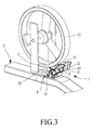
Fig. 3 is another perspective view to show the power generating unit of the present invention connected to an exerciser; -
Fig. 4 is a side view of the power generating unit of the present invention connected to an exerciser; -
Fig. 4a is an enlarged view to show the engagement between the bosses and the arms to set the angular position of the power generating unit, and -
Fig. 5 is a cross sectional view to show the power generating unit of the present invention. - Referring to
Figs. 1 ,2 ,3 ,4 ,4a and5 , thepower generating unit 1 of the present invention is connected to aframe 2 which is connected to anexerciser 5. In this embodiment, theexerciser 5 has an energy transferring end which is aflywheel 51 connected thereto and includes afixing board 6 which is an L-shaped board and includes multipleoval holes 61 to which theframe 2 is connected. - The
power generating unit 1 comprises twoouter casing 12 connected on two sides thereof and eachouter casing 12 has anarm 11. Eachouter casing 12 has aresilient member 4 connected thereto. Thepower generating unit 1 has aninput shaft 13 and aroller 14 is mounted to theinput shaft 13. Each of two ends of theinput shaft 13 has amagnet unit 15 and a Si-steel coil unit 16 connected thereto, themagnet unit 15 is mounted to the Si-steel coil unit 16 by theinner casing 151 thereof and the Si-steel coil unit 16 is fixed to theouter casing 12 corresponding thereto. Each of the Si-steel coil units 16 includes multiple wires which are electrically connected to a control circuit so as to output pre-set voltage and current to the control panel (not shown) of theexerciser 5. Theinput shaft 13 extends centrally through theinner casings 151 of themagnetic unit 15 and theroller 14 is mounted to theinput shaft 13. Theroller 14 is made by silicone rubber or other anti-wearing or anti-contamination material and pivotably connected to theinput shaft 13. Theroller 14 is in contact with theflywheel 51 which is the energy transferring end of theexerciser 5 by theresilient members 4. Each of thearms 11 of theouter casings 12 has aconnection hole 111 and theframe 2 is connected to theouter casings 12 by extendingbolts 7 through theconnection holes 111. - The
frame 2 is connected to theexerciser 5 and has twoconnection tubes 21 on two ends thereof and thebolts 7 extend through theconnection holes 111 and are connected to theconnection tubes 21. A shock-absorbingmember 3 is located beneath theframe 2 which is connected to thefixing board 6 of theexerciser 5 by extendingbolts 7 extending through theoval holes 61 of thefixing board 6. The shock-absorbingmember 3 is made by rubber or other shock-absorbing material and can be integrally formed with theexerciser 5. Theframe 2 includes two semi-circular ends and each of the two semi-circular ends has theresilient member 4 connected thereto which is a torsion spring and fixed to thearm 11 of theouter casing 12. The first end of eachresilient member 4 is fixed to thestop 22 and the second end of eachresilient member 4 is connected to thepower generating unit 1. By theresilient members 4, theroller 14 is in contact with theflywheel 51 which is the energy transferring end of theexerciser 5.Multiple bosses 23 are connected to the two semi-circular ends of theframe 2 and the power generatingunit 1 is positioned by engagement between thebosses 23 and thearms 11. Thebosses 23 are equally distanced from each other so as to set the angular position of thepower generating unit 1. - The shock-absorbing
member 3 absorbs vibration from the power generatingunit 1 when the users operate theexerciser 5. As shown inFigs. 4 and 4a , when theroller 14 is worn out, theroller 4 can still in contact with theflywheel 51 which is the energy transferring end of theexerciser 5, by theresilient members 4 at thearms 11 of theouter casings 12. There will be no gap between theroller 14 and theflywheel 51 even if theexerciser 5 is operated for a long period of time. Therefore, theroller 14 always drives theinput shaft 13 to generate electric power. When theresilient members 4 fail to function properly and cannot urge theroller 14 to contact against theflywheel 51 which is the energy transferring end of theexerciser 5, the position of the shock-absorbingmember 3 can be adjusted by connected to differentoval holes 61 in thefixing board 6 to ensure that theroller 14 still contacts theflywheel 51 which is the energy transferring end of theexerciser 5. Furthermore, theroller 14 is made of silicone rubber or rubber so that it can be used for a longer period of time and is not contaminated. Even if theroller 14 needs to be replaced, the user can simply unscrew thebolts 7 to replace theroller 14. Because theroller 14 is always in contact with the energy transferring end of theexerciser 5, so that the power generating device can be used on wide range of applications. The parts of the power generating device can be easily replaced and have longer life of use, and can be cooperated with different types of exercisers. - The power generating unit does not use any belt to drive the
input shaft 13 which is driven by theroller 14 in contact with the energy transferring end which is theflywheel 51 as shown inFig. 1 , so that the size of thepower generating unit 1 can be minimized. The resilient members ensure that theroller 14 is in contact with the energy transferring end which is theflywheel 51, even if the exerciser is operated for a long period of time. There will be no gap between theroller 14 and the energy transferring end which is theflywheel 51. - The
frame 2 is connected to the shock-absorbingmember 3 which is made by rubber so as to absorb vibration from thepower generating unit 1. - The
roller 14 is made of silicone rubber or rubber so that it can be used for a longer period of time and is not contaminated. Even if theroller 14 needs to be replaced, the user can simply unscrew thebolts 7 to replace theroller 14. - While we have shown and described the embodiment in accordance with the present invention, it should be clear to those skilled in the art that further embodiments may be made without departing from the scope of the present invention.
Claims (8)
- A power generating device comprising:a power generating unit (1) connected to a frame (2) and two outer casings (12) connected on two sides of the power generating unit (1), each outer casing (12) having an arm (11), each outer casing (12) having a resilient member (4), the power generating unit (1) having an input shaft (13), a roller (14) mounted to the input shaft (13), the frame (2) adapted to be connected to an exerciser (5) and a shock-absorbing member (3) located beneath the frame (2), the roller (14) adapted to be in contact with an energy transferring end of the exerciser (5) by the resilient members (4) so as to transfer kinetic energy into electric power.
- The device as claimed in claim 1, wherein each of two ends of the input shaft (13) has a magnet unit (15) and a Si-steel coil unit (16) connected thereto, the magnet unit (15) is mounted to the Si-steel coil unit (16) by an inner casing (151) thereof, the Si-steel coil unit (16) is fixed to the outer casing (12) corresponding thereto, the roller (14) is pivotably connected to the input shaft (13) so as to drive the input shaft (13).
- The device as claimed in claim 1, wherein the fixing board (6) is an L-shaped board and includes multiple oval holes (61) to which the frame (2) is connected.
- The device as claimed in claim 3, wherein the shock-absorbing member (3) is adapted to be connected to the exerciser (5) by extending bolts (7) through the oval holes (61) in the fixing board (6).
- The device as claimed in claim 1, wherein the frame (2) includes two semi-circular ends and each of the two semi-circular ends has the resilient member (4) connected thereto which is a torsion spring and fixed to the arm (11) of the outer casing (12).
- The device as claimed in claim 5, wherein multiple bosses (23) are connected to the two semi-circular ends of the frame (2), the power generating unit (1) is positioned by engagement between the bosses (23) and the arms (11).
- The device as claimed in claim 1, wherein the frame (2) includes a connection tube (21) and a stop (22) connected to each of two ends thereof, the power generating unit (1) has two connection holes (111) and the connection tubes (21) are securely connected to the connection holes (111) by bolts (7).
- The device as claimed in claim 7, wherein each of the resilient members (4) is mounted to the connection tube (21) corresponding thereto, a first end of each resilient member (4) is fixed to the stop (22) and a second end of each resilient member (4) is connected to the power generating unit (1).
Applications Claiming Priority (1)
| Application Number | Priority Date | Filing Date | Title |
|---|---|---|---|
| TW100201172U TWM406444U (en) | 2011-01-19 | 2011-01-19 | Installation of replaceable fitness generator structure having shock-absorbing effect |
Publications (3)
| Publication Number | Publication Date |
|---|---|
| EP2479431A2 true EP2479431A2 (en) | 2012-07-25 |
| EP2479431A3 EP2479431A3 (en) | 2012-11-28 |
| EP2479431B1 EP2479431B1 (en) | 2013-10-30 |
Family
ID=45080241
Family Applications (1)
| Application Number | Title | Priority Date | Filing Date |
|---|---|---|---|
| EP11162739.4A Not-in-force EP2479431B1 (en) | 2011-01-19 | 2011-04-15 | Power generating device connected with exerciser |
Country Status (3)
| Country | Link |
|---|---|
| US (1) | US8672811B2 (en) |
| EP (1) | EP2479431B1 (en) |
| TW (1) | TWM406444U (en) |
Cited By (1)
| Publication number | Priority date | Publication date | Assignee | Title |
|---|---|---|---|---|
| CN102861417A (en) * | 2012-08-31 | 2013-01-09 | 樊荣 | Rocker arm body-building generating device |
Families Citing this family (4)
| Publication number | Priority date | Publication date | Assignee | Title |
|---|---|---|---|---|
| US9283421B2 (en) | 2013-03-21 | 2016-03-15 | E. Gen Llc | Stationary exercise equipment power generator |
| CN103437967B (en) * | 2013-08-19 | 2015-10-28 | 华南理工大学 | A kind of have the adjustable body kinetic energy acquisition equipment of oscillation frequency |
| CN103501079A (en) * | 2013-09-18 | 2014-01-08 | 杜文娟 | Device for controlling bicycle to generate power and charge storage battery with natural force and use method |
| CN108843527A (en) * | 2018-06-26 | 2018-11-20 | 肇庆高新区国专科技有限公司 | A kind of power generator of dibit great wheel |
Family Cites Families (7)
| Publication number | Priority date | Publication date | Assignee | Title |
|---|---|---|---|---|
| US643095A (en) * | 1898-06-30 | 1900-02-06 | Dowd Electrical Company | Magneto-electric lighting apparatus for bicycles. |
| US5050865A (en) * | 1987-12-28 | 1991-09-24 | Quent Augspurger | Cycle training device |
| US6987327B1 (en) * | 2003-07-21 | 2006-01-17 | Gerardo Ramos Lucatero | Electric generating convertible bicycle |
| WO2006102529A2 (en) * | 2005-03-23 | 2006-09-28 | Saris Cycling Group, Inc. | Closed loop control of resistance in a resistance-type exercise system |
| US20070284881A1 (en) * | 2006-06-01 | 2007-12-13 | Mclaughlin Brian | Energy generation device adaptable to a means of rotation |
| US7691030B2 (en) * | 2008-07-24 | 2010-04-06 | Chi-Chang Hsiao | Shock-absorbing device for an exercycle dynamo |
| JP2010259520A (en) * | 2009-04-30 | 2010-11-18 | Motoji Ono | Conveyor structure, tread mill and conveyor |
-
2011
- 2011-01-19 TW TW100201172U patent/TWM406444U/en not_active IP Right Cessation
- 2011-02-15 US US13/028,015 patent/US8672811B2/en not_active Expired - Fee Related
- 2011-04-15 EP EP11162739.4A patent/EP2479431B1/en not_active Not-in-force
Cited By (1)
| Publication number | Priority date | Publication date | Assignee | Title |
|---|---|---|---|---|
| CN102861417A (en) * | 2012-08-31 | 2013-01-09 | 樊荣 | Rocker arm body-building generating device |
Also Published As
| Publication number | Publication date |
|---|---|
| US20120184408A1 (en) | 2012-07-19 |
| TWM406444U (en) | 2011-07-01 |
| US8672811B2 (en) | 2014-03-18 |
| EP2479431B1 (en) | 2013-10-30 |
| EP2479431A3 (en) | 2012-11-28 |
Similar Documents
| Publication | Publication Date | Title |
|---|---|---|
| EP2479431B1 (en) | Power generating device connected with exerciser | |
| US11418099B2 (en) | Vibration actuator and electronic equipment | |
| CN111510532B (en) | Electronic device | |
| KR101101330B1 (en) | Lenear vibration device | |
| US20150375028A1 (en) | Systems and Methods Related to Coupling an Energy Harvester to Exercise Equipment | |
| JP2018503472A (en) | Personal cleaning care tools | |
| TWM438274U (en) | Electric massage device and massage driving structure thereof | |
| US10855155B2 (en) | Permanent magnet linear motor and linear vibrator | |
| CN209403052U (en) | Intelligent grass-removing | |
| JP2005094832A (en) | Generator | |
| CN109139511A (en) | A kind of Intelligent noise reduction radiator fan | |
| KR20170042395A (en) | Generating apparatus | |
| JP3182491U (en) | Power generation device and portable electronic device using the same | |
| CN204029540U (en) | A kind of damping epoxy air-immersed transformer | |
| AU2003258629A1 (en) | Small electrical appliance with a drive device for generation of an oscillating movement | |
| US10536066B2 (en) | Pressed generator, remote control signal transmitter, remote control device and shower equipped with pressed generator | |
| FR2975447B1 (en) | MODULAR ELECTRIC COMPRESSOR WITH ASSEMBLY DEVICE | |
| TW201201486A (en) | Levitation type linear power generation device | |
| CN205754512U (en) | A kind of drop resistant type mobile phone shell being easy to heat radiation | |
| CN203850960U (en) | Anti-falling type motor device | |
| CN215186857U (en) | Magnetic assembly and electronic device | |
| CN104460829A (en) | Electronic device module, electronic device, protective component and working frequency improving method | |
| CN113137350A (en) | Power generation device for electronic equipment and electronic equipment | |
| CN210472578U (en) | Massage gun | |
| AU2003258628A1 (en) | Drive device for the generation of an oscillating movement for a small electrical appliance |
Legal Events
| Date | Code | Title | Description |
|---|---|---|---|
| PUAI | Public reference made under article 153(3) epc to a published international application that has entered the european phase |
Free format text: ORIGINAL CODE: 0009012 |
|
| AK | Designated contracting states |
Kind code of ref document: A2 Designated state(s): AL AT BE BG CH CY CZ DE DK EE ES FI FR GB GR HR HU IE IS IT LI LT LU LV MC MK MT NL NO PL PT RO RS SE SI SK SM TR |
|
| AX | Request for extension of the european patent |
Extension state: BA ME |
|
| PUAL | Search report despatched |
Free format text: ORIGINAL CODE: 0009013 |
|
| AK | Designated contracting states |
Kind code of ref document: A3 Designated state(s): AL AT BE BG CH CY CZ DE DK EE ES FI FR GB GR HR HU IE IS IT LI LT LU LV MC MK MT NL NO PL PT RO RS SE SI SK SM TR |
|
| AX | Request for extension of the european patent |
Extension state: BA ME |
|
| RIC1 | Information provided on ipc code assigned before grant |
Ipc: F03G 7/08 20060101AFI20121019BHEP Ipc: F03G 5/00 20060101ALI20121019BHEP |
|
| 17P | Request for examination filed |
Effective date: 20130219 |
|
| RIC1 | Information provided on ipc code assigned before grant |
Ipc: F03G 7/08 20060101AFI20130306BHEP Ipc: F03G 5/00 20060101ALI20130306BHEP |
|
| GRAP | Despatch of communication of intention to grant a patent |
Free format text: ORIGINAL CODE: EPIDOSNIGR1 |
|
| INTG | Intention to grant announced |
Effective date: 20130517 |
|
| GRAS | Grant fee paid |
Free format text: ORIGINAL CODE: EPIDOSNIGR3 |
|
| GRAA | (expected) grant |
Free format text: ORIGINAL CODE: 0009210 |
|
| AK | Designated contracting states |
Kind code of ref document: B1 Designated state(s): AL AT BE BG CH CY CZ DE DK EE ES FI FR GB GR HR HU IE IS IT LI LT LU LV MC MK MT NL NO PL PT RO RS SE SI SK SM TR |
|
| REG | Reference to a national code |
Ref country code: GB Ref legal event code: FG4D |
|
| REG | Reference to a national code |
Ref country code: CH Ref legal event code: EP |
|
| REG | Reference to a national code |
Ref country code: AT Ref legal event code: REF Ref document number: 638569 Country of ref document: AT Kind code of ref document: T Effective date: 20131115 |
|
| REG | Reference to a national code |
Ref country code: IE Ref legal event code: FG4D |
|
| REG | Reference to a national code |
Ref country code: DE Ref legal event code: R096 Ref document number: 602011003535 Country of ref document: DE Effective date: 20131224 |
|
| REG | Reference to a national code |
Ref country code: NL Ref legal event code: VDEP Effective date: 20131030 |
|
| REG | Reference to a national code |
Ref country code: AT Ref legal event code: MK05 Ref document number: 638569 Country of ref document: AT Kind code of ref document: T Effective date: 20131030 |
|
| REG | Reference to a national code |
Ref country code: LT Ref legal event code: MG4D |
|
| REG | Reference to a national code |
Ref country code: DE Ref legal event code: R082 Ref document number: 602011003535 Country of ref document: DE Representative=s name: CABINET CHAILLOT, FR |
|
| PG25 | Lapsed in a contracting state [announced via postgrant information from national office to epo] |
Ref country code: NL Free format text: LAPSE BECAUSE OF FAILURE TO SUBMIT A TRANSLATION OF THE DESCRIPTION OR TO PAY THE FEE WITHIN THE PRESCRIBED TIME-LIMIT Effective date: 20131030 Ref country code: FI Free format text: LAPSE BECAUSE OF FAILURE TO SUBMIT A TRANSLATION OF THE DESCRIPTION OR TO PAY THE FEE WITHIN THE PRESCRIBED TIME-LIMIT Effective date: 20131030 Ref country code: BE Free format text: LAPSE BECAUSE OF FAILURE TO SUBMIT A TRANSLATION OF THE DESCRIPTION OR TO PAY THE FEE WITHIN THE PRESCRIBED TIME-LIMIT Effective date: 20131030 Ref country code: SE Free format text: LAPSE BECAUSE OF FAILURE TO SUBMIT A TRANSLATION OF THE DESCRIPTION OR TO PAY THE FEE WITHIN THE PRESCRIBED TIME-LIMIT Effective date: 20131030 Ref country code: HR Free format text: LAPSE BECAUSE OF FAILURE TO SUBMIT A TRANSLATION OF THE DESCRIPTION OR TO PAY THE FEE WITHIN THE PRESCRIBED TIME-LIMIT Effective date: 20131030 Ref country code: IS Free format text: LAPSE BECAUSE OF FAILURE TO SUBMIT A TRANSLATION OF THE DESCRIPTION OR TO PAY THE FEE WITHIN THE PRESCRIBED TIME-LIMIT Effective date: 20140228 Ref country code: NO Free format text: LAPSE BECAUSE OF FAILURE TO SUBMIT A TRANSLATION OF THE DESCRIPTION OR TO PAY THE FEE WITHIN THE PRESCRIBED TIME-LIMIT Effective date: 20140130 Ref country code: LT Free format text: LAPSE BECAUSE OF FAILURE TO SUBMIT A TRANSLATION OF THE DESCRIPTION OR TO PAY THE FEE WITHIN THE PRESCRIBED TIME-LIMIT Effective date: 20131030 |
|
| REG | Reference to a national code |
Ref country code: DE Ref legal event code: R082 Ref document number: 602011003535 Country of ref document: DE Representative=s name: CABINET CHAILLOT, FR Effective date: 20140408 Ref country code: DE Ref legal event code: R081 Ref document number: 602011003535 Country of ref document: DE Owner name: DELIGHTECH CORPORATION, TW Free format text: FORMER OWNER: DELIGHTTECH CORP., TAICHUNG, TW Effective date: 20140408 |
|
| PG25 | Lapsed in a contracting state [announced via postgrant information from national office to epo] |
Ref country code: RS Free format text: LAPSE BECAUSE OF FAILURE TO SUBMIT A TRANSLATION OF THE DESCRIPTION OR TO PAY THE FEE WITHIN THE PRESCRIBED TIME-LIMIT Effective date: 20131030 Ref country code: ES Free format text: LAPSE BECAUSE OF FAILURE TO SUBMIT A TRANSLATION OF THE DESCRIPTION OR TO PAY THE FEE WITHIN THE PRESCRIBED TIME-LIMIT Effective date: 20131030 Ref country code: LV Free format text: LAPSE BECAUSE OF FAILURE TO SUBMIT A TRANSLATION OF THE DESCRIPTION OR TO PAY THE FEE WITHIN THE PRESCRIBED TIME-LIMIT Effective date: 20131030 Ref country code: CY Free format text: LAPSE BECAUSE OF FAILURE TO SUBMIT A TRANSLATION OF THE DESCRIPTION OR TO PAY THE FEE WITHIN THE PRESCRIBED TIME-LIMIT Effective date: 20131030 Ref country code: AT Free format text: LAPSE BECAUSE OF FAILURE TO SUBMIT A TRANSLATION OF THE DESCRIPTION OR TO PAY THE FEE WITHIN THE PRESCRIBED TIME-LIMIT Effective date: 20131030 |
|
| PG25 | Lapsed in a contracting state [announced via postgrant information from national office to epo] |
Ref country code: PT Free format text: LAPSE BECAUSE OF FAILURE TO SUBMIT A TRANSLATION OF THE DESCRIPTION OR TO PAY THE FEE WITHIN THE PRESCRIBED TIME-LIMIT Effective date: 20140228 |
|
| RAP2 | Party data changed (patent owner data changed or rights of a patent transferred) |
Owner name: DELIGHTECH CORPORATION |
|
| REG | Reference to a national code |
Ref country code: GB Ref legal event code: S117 Free format text: REQUEST FILED; REQUEST FOR CORRECTION UNDER SECTION 117 FILED ON 20 MARCH 2014 |
|
| PG25 | Lapsed in a contracting state [announced via postgrant information from national office to epo] |
Ref country code: EE Free format text: LAPSE BECAUSE OF FAILURE TO SUBMIT A TRANSLATION OF THE DESCRIPTION OR TO PAY THE FEE WITHIN THE PRESCRIBED TIME-LIMIT Effective date: 20131030 |
|
| REG | Reference to a national code |
Ref country code: DE Ref legal event code: R097 Ref document number: 602011003535 Country of ref document: DE |
|
| PG25 | Lapsed in a contracting state [announced via postgrant information from national office to epo] |
Ref country code: CZ Free format text: LAPSE BECAUSE OF FAILURE TO SUBMIT A TRANSLATION OF THE DESCRIPTION OR TO PAY THE FEE WITHIN THE PRESCRIBED TIME-LIMIT Effective date: 20131030 Ref country code: PL Free format text: LAPSE BECAUSE OF FAILURE TO SUBMIT A TRANSLATION OF THE DESCRIPTION OR TO PAY THE FEE WITHIN THE PRESCRIBED TIME-LIMIT Effective date: 20131030 Ref country code: SK Free format text: LAPSE BECAUSE OF FAILURE TO SUBMIT A TRANSLATION OF THE DESCRIPTION OR TO PAY THE FEE WITHIN THE PRESCRIBED TIME-LIMIT Effective date: 20131030 Ref country code: RO Free format text: LAPSE BECAUSE OF FAILURE TO SUBMIT A TRANSLATION OF THE DESCRIPTION OR TO PAY THE FEE WITHIN THE PRESCRIBED TIME-LIMIT Effective date: 20131030 Ref country code: IT Free format text: LAPSE BECAUSE OF FAILURE TO SUBMIT A TRANSLATION OF THE DESCRIPTION OR TO PAY THE FEE WITHIN THE PRESCRIBED TIME-LIMIT Effective date: 20131030 |
|
| PLBE | No opposition filed within time limit |
Free format text: ORIGINAL CODE: 0009261 |
|
| STAA | Information on the status of an ep patent application or granted ep patent |
Free format text: STATUS: NO OPPOSITION FILED WITHIN TIME LIMIT |
|
| PG25 | Lapsed in a contracting state [announced via postgrant information from national office to epo] |
Ref country code: DK Free format text: LAPSE BECAUSE OF FAILURE TO SUBMIT A TRANSLATION OF THE DESCRIPTION OR TO PAY THE FEE WITHIN THE PRESCRIBED TIME-LIMIT Effective date: 20131030 |
|
| 26N | No opposition filed |
Effective date: 20140731 |
|
| REG | Reference to a national code |
Ref country code: GB Ref legal event code: S117 Free format text: CORRECTIONS ALLOWED; REQUEST FOR CORRECTION UNDER SECTION 117 FILED ON 20 MARCH 2014, ALLOWED ON 15 SEPTEMBER 2014 |
|
| REG | Reference to a national code |
Ref country code: DE Ref legal event code: R097 Ref document number: 602011003535 Country of ref document: DE Effective date: 20140731 |
|
| PG25 | Lapsed in a contracting state [announced via postgrant information from national office to epo] |
Ref country code: LU Free format text: LAPSE BECAUSE OF FAILURE TO SUBMIT A TRANSLATION OF THE DESCRIPTION OR TO PAY THE FEE WITHIN THE PRESCRIBED TIME-LIMIT Effective date: 20140415 Ref country code: MC Free format text: LAPSE BECAUSE OF FAILURE TO SUBMIT A TRANSLATION OF THE DESCRIPTION OR TO PAY THE FEE WITHIN THE PRESCRIBED TIME-LIMIT Effective date: 20131030 |
|
| REG | Reference to a national code |
Ref country code: CH Ref legal event code: PL |
|
| REG | Reference to a national code |
Ref country code: IE Ref legal event code: MM4A |
|
| PG25 | Lapsed in a contracting state [announced via postgrant information from national office to epo] |
Ref country code: LI Free format text: LAPSE BECAUSE OF NON-PAYMENT OF DUE FEES Effective date: 20140430 Ref country code: CH Free format text: LAPSE BECAUSE OF NON-PAYMENT OF DUE FEES Effective date: 20140430 |
|
| PG25 | Lapsed in a contracting state [announced via postgrant information from national office to epo] |
Ref country code: SI Free format text: LAPSE BECAUSE OF FAILURE TO SUBMIT A TRANSLATION OF THE DESCRIPTION OR TO PAY THE FEE WITHIN THE PRESCRIBED TIME-LIMIT Effective date: 20131030 |
|
| PG25 | Lapsed in a contracting state [announced via postgrant information from national office to epo] |
Ref country code: IE Free format text: LAPSE BECAUSE OF NON-PAYMENT OF DUE FEES Effective date: 20140415 |
|
| PG25 | Lapsed in a contracting state [announced via postgrant information from national office to epo] |
Ref country code: MT Free format text: LAPSE BECAUSE OF FAILURE TO SUBMIT A TRANSLATION OF THE DESCRIPTION OR TO PAY THE FEE WITHIN THE PRESCRIBED TIME-LIMIT Effective date: 20131030 |
|
| REG | Reference to a national code |
Ref country code: FR Ref legal event code: PLFP Year of fee payment: 6 |
|
| PG25 | Lapsed in a contracting state [announced via postgrant information from national office to epo] |
Ref country code: SM Free format text: LAPSE BECAUSE OF FAILURE TO SUBMIT A TRANSLATION OF THE DESCRIPTION OR TO PAY THE FEE WITHIN THE PRESCRIBED TIME-LIMIT Effective date: 20131030 |
|
| PG25 | Lapsed in a contracting state [announced via postgrant information from national office to epo] |
Ref country code: BG Free format text: LAPSE BECAUSE OF FAILURE TO SUBMIT A TRANSLATION OF THE DESCRIPTION OR TO PAY THE FEE WITHIN THE PRESCRIBED TIME-LIMIT Effective date: 20131030 Ref country code: GR Free format text: LAPSE BECAUSE OF FAILURE TO SUBMIT A TRANSLATION OF THE DESCRIPTION OR TO PAY THE FEE WITHIN THE PRESCRIBED TIME-LIMIT Effective date: 20140131 |
|
| PG25 | Lapsed in a contracting state [announced via postgrant information from national office to epo] |
Ref country code: HU Free format text: LAPSE BECAUSE OF FAILURE TO SUBMIT A TRANSLATION OF THE DESCRIPTION OR TO PAY THE FEE WITHIN THE PRESCRIBED TIME-LIMIT; INVALID AB INITIO Effective date: 20110415 Ref country code: TR Free format text: LAPSE BECAUSE OF FAILURE TO SUBMIT A TRANSLATION OF THE DESCRIPTION OR TO PAY THE FEE WITHIN THE PRESCRIBED TIME-LIMIT Effective date: 20131030 |
|
| REG | Reference to a national code |
Ref country code: FR Ref legal event code: PLFP Year of fee payment: 7 |
|
| REG | Reference to a national code |
Ref country code: FR Ref legal event code: PLFP Year of fee payment: 8 |
|
| PG25 | Lapsed in a contracting state [announced via postgrant information from national office to epo] |
Ref country code: MK Free format text: LAPSE BECAUSE OF FAILURE TO SUBMIT A TRANSLATION OF THE DESCRIPTION OR TO PAY THE FEE WITHIN THE PRESCRIBED TIME-LIMIT Effective date: 20131030 |
|
| PG25 | Lapsed in a contracting state [announced via postgrant information from national office to epo] |
Ref country code: AL Free format text: LAPSE BECAUSE OF FAILURE TO SUBMIT A TRANSLATION OF THE DESCRIPTION OR TO PAY THE FEE WITHIN THE PRESCRIBED TIME-LIMIT Effective date: 20131030 |
|
| PGFP | Annual fee paid to national office [announced via postgrant information from national office to epo] |
Ref country code: DE Payment date: 20190426 Year of fee payment: 9 |
|
| PGFP | Annual fee paid to national office [announced via postgrant information from national office to epo] |
Ref country code: FR Payment date: 20190416 Year of fee payment: 9 |
|
| PGFP | Annual fee paid to national office [announced via postgrant information from national office to epo] |
Ref country code: GB Payment date: 20190425 Year of fee payment: 9 |
|
| REG | Reference to a national code |
Ref country code: DE Ref legal event code: R119 Ref document number: 602011003535 Country of ref document: DE |
|
| PG25 | Lapsed in a contracting state [announced via postgrant information from national office to epo] |
Ref country code: DE Free format text: LAPSE BECAUSE OF NON-PAYMENT OF DUE FEES Effective date: 20201103 Ref country code: FR Free format text: LAPSE BECAUSE OF NON-PAYMENT OF DUE FEES Effective date: 20200430 |
|
| GBPC | Gb: european patent ceased through non-payment of renewal fee |
Effective date: 20200415 |
|
| PG25 | Lapsed in a contracting state [announced via postgrant information from national office to epo] |
Ref country code: GB Free format text: LAPSE BECAUSE OF NON-PAYMENT OF DUE FEES Effective date: 20200415 |