EP2479403A2 - Combustion engine - Google Patents
Combustion engine Download PDFInfo
- Publication number
- EP2479403A2 EP2479403A2 EP12000374A EP12000374A EP2479403A2 EP 2479403 A2 EP2479403 A2 EP 2479403A2 EP 12000374 A EP12000374 A EP 12000374A EP 12000374 A EP12000374 A EP 12000374A EP 2479403 A2 EP2479403 A2 EP 2479403A2
- Authority
- EP
- European Patent Office
- Prior art keywords
- crankshaft
- engine
- shaft
- lubricant oil
- kick
- Prior art date
- Legal status (The legal status is an assumption and is not a legal conclusion. Google has not performed a legal analysis and makes no representation as to the accuracy of the status listed.)
- Withdrawn
Links
Images


Classifications
-
- F—MECHANICAL ENGINEERING; LIGHTING; HEATING; WEAPONS; BLASTING
- F01—MACHINES OR ENGINES IN GENERAL; ENGINE PLANTS IN GENERAL; STEAM ENGINES
- F01M—LUBRICATING OF MACHINES OR ENGINES IN GENERAL; LUBRICATING INTERNAL COMBUSTION ENGINES; CRANKCASE VENTILATING
- F01M11/00—Component parts, details or accessories, not provided for in, or of interest apart from, groups F01M1/00 - F01M9/00
- F01M11/02—Arrangements of lubricant conduits
-
- F—MECHANICAL ENGINEERING; LIGHTING; HEATING; WEAPONS; BLASTING
- F01—MACHINES OR ENGINES IN GENERAL; ENGINE PLANTS IN GENERAL; STEAM ENGINES
- F01M—LUBRICATING OF MACHINES OR ENGINES IN GENERAL; LUBRICATING INTERNAL COMBUSTION ENGINES; CRANKCASE VENTILATING
- F01M11/00—Component parts, details or accessories, not provided for in, or of interest apart from, groups F01M1/00 - F01M9/00
- F01M11/03—Mounting or connecting of lubricant purifying means relative to the machine or engine; Details of lubricant purifying means
-
- F—MECHANICAL ENGINEERING; LIGHTING; HEATING; WEAPONS; BLASTING
- F02—COMBUSTION ENGINES; HOT-GAS OR COMBUSTION-PRODUCT ENGINE PLANTS
- F02B—INTERNAL-COMBUSTION PISTON ENGINES; COMBUSTION ENGINES IN GENERAL
- F02B61/00—Adaptations of engines for driving vehicles or for driving propellers; Combinations of engines with gearing
- F02B61/02—Adaptations of engines for driving vehicles or for driving propellers; Combinations of engines with gearing for driving cycles
-
- F—MECHANICAL ENGINEERING; LIGHTING; HEATING; WEAPONS; BLASTING
- F02—COMBUSTION ENGINES; HOT-GAS OR COMBUSTION-PRODUCT ENGINE PLANTS
- F02B—INTERNAL-COMBUSTION PISTON ENGINES; COMBUSTION ENGINES IN GENERAL
- F02B75/00—Other engines
- F02B75/16—Engines characterised by number of cylinders, e.g. single-cylinder engines
-
- F—MECHANICAL ENGINEERING; LIGHTING; HEATING; WEAPONS; BLASTING
- F16—ENGINEERING ELEMENTS AND UNITS; GENERAL MEASURES FOR PRODUCING AND MAINTAINING EFFECTIVE FUNCTIONING OF MACHINES OR INSTALLATIONS; THERMAL INSULATION IN GENERAL
- F16H—GEARING
- F16H57/00—General details of gearing
- F16H57/04—Features relating to lubrication or cooling or heating
- F16H57/048—Type of gearings to be lubricated, cooled or heated
- F16H57/0487—Friction gearings
- F16H57/0489—Friction gearings with endless flexible members, e.g. belt CVTs
-
- F—MECHANICAL ENGINEERING; LIGHTING; HEATING; WEAPONS; BLASTING
- F02—COMBUSTION ENGINES; HOT-GAS OR COMBUSTION-PRODUCT ENGINE PLANTS
- F02B—INTERNAL-COMBUSTION PISTON ENGINES; COMBUSTION ENGINES IN GENERAL
- F02B75/00—Other engines
- F02B75/02—Engines characterised by their cycles, e.g. six-stroke
- F02B2075/022—Engines characterised by their cycles, e.g. six-stroke having less than six strokes per cycle
- F02B2075/027—Engines characterised by their cycles, e.g. six-stroke having less than six strokes per cycle four
-
- F—MECHANICAL ENGINEERING; LIGHTING; HEATING; WEAPONS; BLASTING
- F02—COMBUSTION ENGINES; HOT-GAS OR COMBUSTION-PRODUCT ENGINE PLANTS
- F02B—INTERNAL-COMBUSTION PISTON ENGINES; COMBUSTION ENGINES IN GENERAL
- F02B2275/00—Other engines, components or details, not provided for in other groups of this subclass
- F02B2275/20—SOHC [Single overhead camshaft]
-
- F—MECHANICAL ENGINEERING; LIGHTING; HEATING; WEAPONS; BLASTING
- F16—ENGINEERING ELEMENTS AND UNITS; GENERAL MEASURES FOR PRODUCING AND MAINTAINING EFFECTIVE FUNCTIONING OF MACHINES OR INSTALLATIONS; THERMAL INSULATION IN GENERAL
- F16H—GEARING
- F16H57/00—General details of gearing
- F16H57/02—Gearboxes; Mounting gearing therein
- F16H2057/0203—Gearboxes; Mounting gearing therein the gearbox is associated or combined with a crank case of an engine
-
- F—MECHANICAL ENGINEERING; LIGHTING; HEATING; WEAPONS; BLASTING
- F16—ENGINEERING ELEMENTS AND UNITS; GENERAL MEASURES FOR PRODUCING AND MAINTAINING EFFECTIVE FUNCTIONING OF MACHINES OR INSTALLATIONS; THERMAL INSULATION IN GENERAL
- F16H—GEARING
- F16H57/00—General details of gearing
- F16H57/02—Gearboxes; Mounting gearing therein
- F16H2057/02039—Gearboxes for particular applications
- F16H2057/02043—Gearboxes for particular applications for vehicle transmissions
- F16H2057/02065—Gearboxes for particular applications for vehicle transmissions for motorcycles or squads
-
- F—MECHANICAL ENGINEERING; LIGHTING; HEATING; WEAPONS; BLASTING
- F16—ENGINEERING ELEMENTS AND UNITS; GENERAL MEASURES FOR PRODUCING AND MAINTAINING EFFECTIVE FUNCTIONING OF MACHINES OR INSTALLATIONS; THERMAL INSULATION IN GENERAL
- F16H—GEARING
- F16H57/00—General details of gearing
- F16H57/02—Gearboxes; Mounting gearing therein
- F16H57/035—Gearboxes for gearing with endless flexible members
-
- F—MECHANICAL ENGINEERING; LIGHTING; HEATING; WEAPONS; BLASTING
- F16—ENGINEERING ELEMENTS AND UNITS; GENERAL MEASURES FOR PRODUCING AND MAINTAINING EFFECTIVE FUNCTIONING OF MACHINES OR INSTALLATIONS; THERMAL INSULATION IN GENERAL
- F16H—GEARING
- F16H57/00—General details of gearing
- F16H57/04—Features relating to lubrication or cooling or heating
- F16H57/0402—Cleaning of lubricants, e.g. filters or magnets
- F16H57/0404—Lubricant filters
-
- F—MECHANICAL ENGINEERING; LIGHTING; HEATING; WEAPONS; BLASTING
- F16—ENGINEERING ELEMENTS AND UNITS; GENERAL MEASURES FOR PRODUCING AND MAINTAINING EFFECTIVE FUNCTIONING OF MACHINES OR INSTALLATIONS; THERMAL INSULATION IN GENERAL
- F16H—GEARING
- F16H57/00—General details of gearing
- F16H57/04—Features relating to lubrication or cooling or heating
- F16H57/0467—Elements of gearings to be lubricated, cooled or heated
- F16H57/0475—Engine and gearing, i.e. joint lubrication or cooling or heating thereof
Definitions
- the present invention relates to an engine with a V-belt type continuously variable transmission positioned on one side of an engine case. Further, the invention relates to a vehicle, in particular a motorcycle.
- Some of the engines for use on motorcycles are provided with a CVT located on the axially outer side of the engine case and housing a V-belt type of CVT mechanism in a transmission case.
- a CVT located on the axially outer side of the engine case and housing a V-belt type of CVT mechanism in a transmission case.
- the transmission case occupies one side of the engine case, a problem of increased lateral and longitudinal engine dimensions may occur depending on the arrangement of engine accessories such as parts constituting the lubricating and starting systems.
- a conventional type of engine of the above kind with a V-belt type of CVT has, for example, an arrangement wherein an oil filter of the lubricating system is removably attached to and protruding on the side wall of the engine case, as it is disclosed in JP-A-2002-021989 A .
- the described arrangement of the kick shaft has a problem of increased lateral engine dimension, too, because the mechanism for transmitting the rotation of the kick shaft to the crankshaft is disposed on the outer side of the generator of the engine case in the lateral direction.
- this object is solved in an inventive manner in that a filter chamber housing a lubricating oil filter is provided at a side of said engine case which is opposite to the side of said continuously variable transmission, said filter chamber overlapping with at least a part of a generator of said engine in a crankshaft direction, and/or in that a kick shaft is placed at a side of said engine case which is opposite to the side at which said continuously variable transmission is positioned, and/or in that the kick shaft is placed, as seen in a crankshaft direction, below a transmission shaft of said continuously variable transmission and/or an output shaft of a clutch mechanism connected to said transmission shaft, and/or in that a center of a lubricant oil chamber for collecting lubricating oil is offset in a crankshaft direction to the side of said continuously variable transmission with respect to an engine center line passing through a cylinder axis of the engine, and/or in that at least one of: a series of kick gears for transmitting the rotation of a kick shaft to a crankshaft
- said continuously variable transmission is provided with and houses in a transmission case a drive pulley attached to one end of a crankshaft of the engine, a driven pulley attached to one end of a transmission shaft being parallel to said crankshaft, and a V-belt routed around the drive and driven pulleys, and/or in that said generator is attached to the end of said crankshaft opposite to the side to which said continuously variable transmission is attached, and/or in that said filter chamber is positioned in a depressed manner overlapping with at least a part of a lubricating oil chamber of the engine when viewed in the crankshaft direction.
- said filter chamber is located below a first plane which includes an axis of a crankshaft of the engine and an axis of a transmission shaft of the continuously variable transmission, wherein preferably said filter chamber is located between a second plane orthogonal to said first plane and including the axis of said crankshaft and a third plane orthogonal to said first plane and including the axis of said transmission shaft.
- a clutch mechanism is attached to a transmission shaft of said continuously variable transmission, wherein said clutch mechanism overlaps at least in part with a crank arm of a crankshaft of the engine in the crankshaft direction, wherein an axis of said filter chamber is located adjacent to a bottom edge of said clutch mechanism, and/or wherein said filter chamber is separated from said clutch mechanism in the crankshaft direction.
- an exhaust pipe is connected to an exhaust opening of a cylinder which is oriented in a forward direction of said engine case, the exhaust pipe being connected to the engine case and passing below said transmission case and/or along a side of a bottom of said engine case in a backward direction of the engine case.
- a lubricant oil chamber for collecting lubricating oil is disposed below a crank chamber and offset to the side of the engine case at which said continuously variable transmission is positioned, wherein at least a part of said filter chamber overlaps with said lubricant oil chamber as seen in the crankshaft direction.
- an engine is provided with a V-belt type continuously variable transmission positioned on one side of an engine case, wherein a kick shaft is placed at a side of said engine case which is opposite to the side at which said continuously variable transmission is positioned, and/or in that the kick shaft is placed, as seen in a crankshaft direction, below a transmission shaft of said continuously variable transmission and/or an output shaft of a clutch mechanism connected to said transmission shaft.
- said transmission shaft and said output shaft are coaxially disposed, and/or in that said kick shaft is located approximately directly below said output shaft and/or overlaps with both, a driven pulley of said continuously variable transmission and said clutch mechanism.
- a kick gear attached to said kick shaft is capable of engaging with a first intermediate gear attached to one end of an intermediate shaft
- a second intermediate gear attached to an opposite end of said intermediate shaft is capable of engaging with a crank gear attached to said crankshaft
- said kick gear and said first intermediate gear are disposed in an inner side of a support wall portion for supporting a journal portion of said crankshaft on the side opposite the side of said continuously variable transmission
- said second intermediate gear and said crank gear are disposed on the outer side of said support wall portion.
- an engine is provided with a V-belt, wherein a center of a lubricant oil chamber for collecting lubricating oil is offset in a crankshaft direction to the side of said continuously variable transmission with respect to an engine center line passing through a cylinder axis of the engine, and/or in that at least one of: a series of kick gears for transmitting the rotation of a kick shaft to a crankshaft of the engine, a series of pump gears for transmitting the rotation of said crankshaft to a lubricant oil pump, a series of starting gears for transmitting the rotation of a starter to said crankshaft, and/ or a series of balancer gears for transmitting the rotation of said crankshaft to a balancer shaft, is offset in the crankshaft direction to a side of the engine case which is opposite to the side of said continuously variable transmission with respect to a center of a lubricant oil chamber and/or an engine center line.
- a side wall of said lubricant oil chamber at the side of the engine case opposite to the continuously variable transmission is constituted of a support wall portion supporting a journal portion of said crankshaft on the side of the engine case opposite to said continuously variable transmission, and/or in that at least one of said series of kick gears, said series of pump gears, said series of starting gears, and said series of balancer gears is disposed along said support wall portion.
- said lubricant oil chamber is located in an area reaching from a lower part of a crank chamber of said engine case to a lower part of said transmission case.
- a generator is attached to an end of said crankshaft which is opposite to said side of said continuously variable transmission, and/or in that at least one of said series of kick gears, said series of pump gears, series of starting gears, and series of balancer gears passes between said generator and said support wall portion and is connected to said crankshaft.
- a filter chamber is disposed in a depressed manner on the side surface of said engine case opposite to said continuously variable transmission overlapping at least in part with a generator wherein preferably an oil filter for filtering lubricant oil is provided in said filter chamber.
- At least a part of said filter chamber overlaps with any one of said series of kick gears, said series of pump gears, series of starting gears, and series of balancer gears as seen in the crankshaft direction.
- said series of kick gears is constituted that a kick gear attached to said kick shaft is capable of engaging with a first intermediate gear attached to one end of an intermediate shaft, a second intermediate gear attached to an opposite end of said intermediate shaft is capable of engaging with a crank gear attached to said crankshaft, said kick gear and said first intermediate gear are disposed on an inner side of a support wall portion, and said second intermediate gear and said crank gear are disposed on an outer side of said support wall portion.
- said series of pump gears is constituted to transmit a rotation of said crank gear attached between a support wall portion of said crankshaft and said generator to a pump gear via an intermediate gear, and/or said pump gear is attached to a rotational shaft of said lubricant oil pump attached to a portion of said support wall portion constituting the side wall of said lubricant oil chamber.
- At least a portion of said lubricant oil chamber, in particular a swell portion thereof, is arranged next to and/or reaches below a drive pulley of said V-belt type continuously variable transmission, in particular when seen in a sectional view cutting through a pump shaft of a lubricating oil pump and a crankshaft of the engine.
- At least a portion of said lubricant oil chamber, in particular a swell portion thereof, is arranged next to and/or reaches below a driven pulley of said V-belt type continuously variable transmission and/or a clutch mechanism and/or an output shaft, in particular when seen in a sectional view cutting through a filter chamber and an output shaft of said V-belt type continuously variable transmission.
- At least a portion of said lubricant oil chamber, in particular a swell portion thereof, protruding outwardly form a side of the engine is arranged at a lower side of a transmission case of said V-belt type continuously variable transmission, in particular when seen in a direction parallel with a crankshaft of the engine.
- said lubricant oil chamber is located below a first plane which includes an axis of a crankshaft of the engine and an axis of an output shaft of the continuously variable transmission, wherein preferably a main portion of said lubricant oil chamber is located between a second plane orthogonal to said first plane and including the axis of said crankshaft and a third plane orthogonal to said first plane and including the axis of said transmission shaft.
- the lubricant oil chamber is disposed below a crank chamber and/or shifted to the side of a transmission case of the continuously variable transmission, wherein preferably at least a part of the lubricant oil chamber overlaps with a filter chamber, as seen in the crankshaft direction.
- an exhaust pipe extends along a transmission case of the continuously variable transmission and a lateral side of the lubricant oil chamber.
- a center of said lubricant oil chamber of is defined by a virtual plane cutting vertically through a crankshaft of the engine and having an about equal distance to inner sides of side walls of the lubricant oil chamber, in particular when measured in a sectional view cutting through a pump shaft of a lubricating oil pump and a crankshaft of the engine, wherein preferably one of the side walls is an inside wall supporting the lubricating oil pump and/or the other side wall is a side wall of a swell portion of said lubricant oil chamber.
- the above object is solved in an inventive manner in that the vehicle, being in particular a motorcycle, comprises an engine according to at least one of the claims 1 to 24.
- engine case is a general term including the following cases: the crankcase in which the crankshaft is placed, the clutch case in which the clutch mechanism is housed, and the generator case in which the generator is placed.
- Each case is formed partially or wholly to be integral with other case or cases, or separately formed.
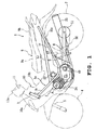
- an engine 2 of this embodiment is mounted on the motorcycle 1, a head pipe 3 is secured to the front end of a vehicle body frame 1 a to support a front fork 5 that is capable of turning right and left about its axis and supports a front wheel 4 with a shaft, a rear arm bracket 6 secured to the central part of the vehicle frame 1 a to support a rear arm 8 which supports a rear wheel 7 with a shaft for up and down swinging, and a seat 9 made up of a front rider's seat 9a and a rear rider's seat 9b is mounted on the vehicle body frame 1 a.
- the vehicle body frame 1a is made up of right and left down tubes 1b extending from the head pipe 3 obliquely rear downward, right and left upper tubes 1 c extending from the rear ends of the down tubes 1 b obliquely rear upward, and right and left seat rails 1 d extending in the longitudinal direction of the vehicle to interconnect the down tubes 1b and upper tubes 1 c.
- the vehicle body frame 1 a is surrounded with a resinous vehicle body cover 10 made up of a front cover 10a, a leg shield 10b, and a side cover 10c.
- Steering handlebars 11 are secured to the upper end of the front fork 5 and surrounded with a handlebars cover 11 a.
- a rear damper 12 is suspended between the rear arm 8 and the rear arm bracket 6.
- the engine 2 is an air-cooled, four-stroke, single cylinder engine and suspension-supported between rear lower parts of the down tubes 1 b, with its cylinder axis tilted forward by about 45 degrees.
- the engine 2 comprises an engine unit 15 and a V-belt type of CVT 16, and the engine case of the engine unit 15 houses a wet type, multi-plate, centrifugal clutch mechanism 17 and a reduction gear mechanism 18.
- the engine unit 15 in rough description, is constituted with a cylinder block 19, a cylinder head 20 placed on the top mating surface of the cylinder block 19, a head cover 21 placed over the cylinder head 20, a crankcase 22 attached to the bottom mating surface of the cylinder block 19 to house a crankshaft 28, and a generator case 44 attached on the left side of the crankcase 22.
- the engine case of this embodiment is made up of the crankcase 22 and the generator case 44.
- the rear surface of the cylinder head 20 is provided with an intake port 20b connected to a combustion recess 20a.
- the intake port 20b is connected through an intake pipe 23a to a carburetor 23.
- the front surface of the cylinder head 20 is provided with an exhaust port 20c connected to the combustion recess 20a.
- An exhaust pipe 24 is connected to the exhaust port 20c.
- the exhaust pipe 24 extends obliquely toward the right lower side of the engine, along under the transmission case 45 (to be described later) and the right side of a swelled portion 22b of a lubricant oil chamber, and obliquely rearward along the vehicle body and is connected to a muffler 25 disposed on the right side of the rear wheel 7.
- an electrode of an ignition plug 30 inserted obliquely downward from the right side of the engine.
- the cylinder block 19 has a chain chamber 19a formed on the left side and interconnecting the interior of the crankcase 22 and the interior of the cylinder head 20.
- a timing chain 34 placed in the chain chamber 19a drives a camshaft 31 that drives to open and close an intake valve 32 and an exhaust valve 33 with the crankshaft 28.
- a piston 26 for free sliding therein.
- the piston 26 is connected to the small end 27b of a connecting rod 27.
- a transmission shaft 47 is placed behind and parallel to the crankshaft 28.
- An output shaft 48 is placed coaxially and to the left of the transmission shaft 47.
- the output shaft 48 at its left end protruding out of the crankcase, is provided with a drive sprocket 49 linked through a chain 50 with a driven sprocket 51 on the rear wheel 7.
- a generator 42 is attached to the left end of the crankshaft 28 located on the opposite side of the transmission case 45.
- the generator 42 is constituted with a sleeve 43 taper-fitted onto the crankshaft 28, a rotor 42a secured to the sleeve 43, and a stator 42b in a position radially opposite the rotor 42a and secured to a boss portion 42c coaxially with the crankshaft of the generator case 44.
- the crankcase 22 is split into the first case 40 on the left side in the crankshaft direction and the second case 41 on the right side.
- the generator case 44 for housing the generator 42 is removably attached to the left side, in the crankshaft direction, of the first case 40.
- the transmission case 45 serving to house the CVT 16 is attached to the right side, in the crankshaft direction, of the second case 41.
- the parting line B of the first and second cases 40 and 41 is slightly displaced to the left of the cylinder axis A (engine center line).
- the first and second cases 40 and 41 are constituted, in rough description, with first and second peripheral walls 40a and 41 a that are generally open toward outside in the crankshaft direction, on the inner side of which are integrally formed first and second support walls 40b and 41 b that support the crankshaft 28.
- the first support wall 40b of the first case 40 has a left journal support wall portion 40c for supporting, through a left side journal bearing 35, the left crank journal portion 28c of the crankshaft 28, and a reduction gear mechanism support wall portion 40d formed to project in a stepped manner a small amount to the left in the crankshaft direction relative to the left journal support wall portion 40c.
- the second support wall 41 b of the second case 41 has a right journal support wall portion 41 c for supporting the right crank journal portion 28d of the crankshaft 28 through a right side journal bearing 36, and a clutch support wall portion 41 d formed to project in a stepped manner to the left in the crankshaft direction relative to the right journal support wall portion 41 c.
- crank arms 28a, 28b, and the crank pin 29 of the crankshaft 28 are housed in the crank chamber 37 formed with the left and right journal crank support wall portions 40c and 41 c.
- the centrifugal clutch mechanism 17 is housed in a clutch chamber 38 formed with the second peripheral wall 41 a and the clutch support wall portion 41 d.
- the clutch chamber 38 is separated from the crank chamber 37 and communicates with the crank chamber 37 through an opening 103 described later.
- a reduction chamber 39 is formed with the reduction gear mechanism support wall portion 40d and the clutch support wall portion 41 d to house the reduction gear mechanism 18, and directly communicates with the crank chamber 37 without separation.
- the reduction gear mechanism 18 is constituted as follows: A reduction shaft 52 is provided parallel to the transmission shaft 47 between the support wall portions 40d and 41 d. The right side portion of the reduction shaft 52 is supported through a reduction shaft bearing 53 with the clutch support wall portion 41 d while its left side portion is supported through a reduction shaft bearing 54 with a recess 40e formed in the reduction gear mechanism support wall portion 40d. A primary reduction small gear 74 capable of making relative rotation is attached to the transmission shaft 47 placed in the clutch chamber 38. A primary reduction large gear 75 engaging with the primary reduction small gear 74 is secured with a key to the reduction shaft 52. The reduction shaft 52 located in the reduction chamber 39 is integrally formed with a secondary reduction small gear 52a. A secondary reduction large gear 48a engaging with the secondary reduction small gear 52a is integrally formed with the output shaft 48.
- the output shaft 48 is placed coaxially with the transmission shaft 47.
- the right end portion of the output shaft 48 is disposed with a support hole 48b in a depressed manner into which the left end portion of the transmission shaft 47 is to be inserted.
- the right end portion of the output shaft 48 is supported with the left end portion of the transmission shaft 47 through a bearing 76 attached in the support hole 48b.
- the left end portion of the output shaft 48 is passed through and supported with the reduction gear mechanism support wall portion 40d of the first case 40 through a bearing 77.
- the drive sprocket 49 is secured to the projecting end portion of the output shaft 48.
- the CVT 16 is constituted with the drive pulley 55 attached to the right outside end portion of the crankshaft 28, the driven pulley 56 attached to the right outside end of the transmission shaft 47, and the V-belt 57 routed around both the drive pulley and the driven pulley to be connected to each other.
- the V-belt 57 is made of resin that is heat resistant and durable. Details of the constitution are as follows. A large number of resin blocks 57a, made of a material such as polyamide resin mixed with carbon fibers or aramid fibers and formed in the shape of H lying on its side, are placed in succession and joined together by fitting pairs of ring-shaped connecting members 57b made of highly heat resistant rubber thereonto.
- the drive pulley 55 is made up of a fixed pulley half 55a and a movable pulley half 55b, with the former fixed to the right end portion of the crankshaft 28 while the latter placed on the inner side, in the crankshaft direction, of the fixed pulley half 55a, arranged to be axially slidable and rotatable together with the crankshaft 28 through a slide collar 59.
- a cam plate 58 and the slide collar 59 are spline-fitted onto the right end portion of the crankshaft 28, on the axially outer side of which is attached the fixed pulley half 55a and secured by means of a locking nut 60.
- Cylindrical weights 61 are placed between the movable pulley half 55b and the cam plate 58. As the crankshaft 28 rotates faster, the weights 61 move radially outward by centrifugal force to move the movable pulley half 55b axially outward and increase the routing radius of the pulley. As a result, reduction ratio decreases.
- the driven pulley 56 is made up of a fixed pulley half 56a and a movable pulley half 56b, with the former fixed to the right outside end portion of the transmission shaft 47 while the latter placed on the outer side, in the crankshaft direction, of the fixed pulley half 56a, to be axially slidable.
- a cylindrical slide collar 62 secured to the axially central portion of the fixed pulley half 56a is spline-fitted onto the transmission shaft 47.
- a cylindrical boss member 63 secured to the axially central portion of the movable pulley half 56b is fitted, to be axially movable, onto the slide collar 62.
- Guide pins 64 planted into the slide collar 62 engage with slide grooves 63a formed in the boss member 63 so that the guide pins 64 can slide and the movable pulley half 56b can rotate together with the fixed pulley half 56a.
- a spring receiving member 65 of an annular plate shape is attached at the fore-end portion of the slide collar 62 at the fore-end portion of the slide collar 62.
- a coil spring 67 for constantly urging the movable pulley half 56b toward the fixed pulley half 56a is interposed between the spring receiving member 65 and the movable pulley half 56b.
- the driven pulley 56 is pushed into a position recessed from the fore-end portion 62a of the slide collar 62 and secured to the transmission shaft 47 by means of a locking nut 66 screwed to the fore-end 47a of the transmission shaft 47.
- the inside diameter of the slide collar 62 is stepped to a diameter larger than the outside diameter of the transmission shaft 47, and the fore-end portion 47a of the transmission shaft 47 is stepped to a smaller diameter.
- the locking nut 66 and the washer 66a can be placed smoothly in the slide collar 62. In this way, it is possible to place the locking nut 66 toward the inner side in the crankshaft direction from the spring receiving member 65 for the coil spring 67.
- this embodiment is arranged that the movable pulley half 56b of the driven pulley 56 attached to the transmission shaft 47 is located on the outer side in the crankshaft direction of the fixed pulley half 56a, it is possible to secure a free space on the inner side of the driven pulley 56 of the transmission shaft 47 and use the space for placing the centrifugal clutch mechanism 17 adjacent to the fixed pulley half 56a.
- This makes it possible to coaxially place the output shaft 48 on part of the transmission shaft 47 located on the opposite side of the driven pulley 56 without increasing the engine width.
- the engine size can be reduced in the longitudinal direction of the vehicle.
- this embodiment is arranged that the locking nut 66 is placed in an axially recessed position using the spring receiving member 65 that supports the coil spring 67 for urging the movable pulley half 56b against the fixed pulley half 56a, it is possible to restrict the dimension of the engine from increasing in the vehicle width direction by reducing the amount of protrusion of the coil spring 67 toward the outer side in the transmission shaft direction with a simple constitution while securing necessary length of the coil spring 67.
- a transmission case 204 protrudes outward in the vehicle width direction according to the size of the locking nut 203.
- this embodiment is arranged that the locking nut 66 is placed in an axially recessed position from the outside end of the spring receiving member 65, so that the protrusion of the transmission case 45 is reduced by a dimension of (t), about 10 mm.
- the coil spring 67 Since the coil spring 67 is located on the axially outer side, the coil spring 67 can be serviced easily after only removing the retaining ring 65a. If the movable pulley half were placed inside the fixed pulley half, or if the coil spring were placed axially on the inner side, servicing work efficiency would become poor because the entire driven pulley would have to be removed.
- the transmission case 45 is constituted to be generally sealed and formed to be separate from or independent of the crankcase 22 in an elliptic shape as seen from the right ( FIG. 4 ) so as to cover most of the upper side of the crankcase 22.
- the transmission case 45 is constituted with a case 45a of a bottomed box shape that is open toward the outer side in the crankshaft direction, and a lid 45b that closes the opening in airtight state, and is secured to the second case 41 using bolts 70.
- the case 45a is made of molded resin and the lid 45b is made of cast aluminum alloy.
- a space (a) is formed between the bottom wall 45c of the case 45a and the second case 41 and restricts the heat of the engine 2 from being transmitted to the transmission case 45. Further, since the case 45a is made of molded resin, heat of the engine 2 can be restricted from being transmitted to the transmission case 45 in terms thereof.
- a clutch cover 71 is attached in oil-tight state to the opening 41 e.
- the clutch cover 71 is removably fixed to the opening edge of the second peripheral wall 41 a by means of bolts 72. In this way, the transmission case 45 can be removed together with the driven pulley 56, and the centrifugal clutch mechanism 17 can be removed together with the transmission shaft 47 after removing the clutch cover 71.
- the centrifugal clutch mechanism 17 is positioned and supported to be axially immovable with clutch bearings 80 on one side and 81 on the other side, with the former attached to the axially left end and the latter in the center of the transmission shaft 47.
- the clutch bearing 80 on one side is supported with the clutch support wall portion 41 d.
- the clutch bearing 81 on the other side is supported with the clutch cover 71.
- the clutch support wall portion 41 d that supports the clutch bearing 80 and the reduction shaft bearing 53 is displaced toward the left of the second crank support wall portion 41 c that supports the right hand journal bearing 36. In other words, it is located between the first crank support wall portion 40c that supports the left journal bearing 35 and the second crank support wall portion 41c. More concretely, it is located on the cylinder axis A or slightly displaced from the cylinder axis A toward the parting line B.
- the clutch cover 71 that supports the clutch bearing 81 on the other side is located more on the right outer side in the crankshaft direction than the second crank support wall portion 41 b that supports the right journal bearing 36.
- the reduction gear mechanism support wall portion 40d that supports the left side bearing 77 of the output shaft 48 is located more on the left outer side than the first crank support wall portion 40c that supports the left journal bearing 35.
- the transmission case 45 can be made in a sealed constitution to prevent water and dust from entering inside.
- Using the resinous belt 57 with enhanced durability makes it possible to reduce the outside diameters of the drive pulley 55 and the driven pulley 56, and accordingly, the distance between axes of the drive pulley 55 and the driven pulley 56 so that the engine as a whole is made compact.
- the transmission case 45 is made in a sealed constitution separate from or independent of the crankcase 22. Therefore, the space (a) provided between the crankcase 22 and the transmission case 45 blocks engine heat, preventing heat of the engine 2 from being transmitted to the transmission case 45 and restricting temperature rise in the belt chamber.
- the crankcase 22 is parted in the crankshaft direction into the first and second cases 40 and 41.
- the transmission case 45 is placed on the outer side in the crankshaft direction of the second case 41.
- the centrifugal clutch mechanism 17 is located in the vicinity on the inner side in the crankshaft direction of the transmission case 45.
- centrifugal clutch mechanism 17 Since the centrifugal clutch mechanism 17 is supported at two points with one and the other clutch bearings 80 and 81 attached to the transmission shaft 47, the centrifugal clutch mechanism 17 is positioned in the axial direction and supported with a simple constitution without using separate components.
- This embodiment is arranged that the clutch support wall portion 41 d that supports the clutch bearing 80 on one side is placed between the first and second crank support wall portions 40c and 41 c that support the left and right journal bearings 35 and 36 of the crankshaft 28 and the clutch cover 71 (wall for supporting the other side of the clutch) that supports the clutch bearing 81 on the other side is located on the outer side in the crankshaft direction of the second crank support wall portion 41 c that supports the right journal bearing 36.
- the clutch cover 71 is removably attached to the opening 41 e of the second case 41, the work of maintenance and replacing parts can be made easily because the centrifugal clutch 17 can be removed together with the transmission shaft 47 after the transmission case 45 and the clutch cover 71 are removed.
- the output shaft 48 is located coaxially on the side, opposite the transmission case 45, of the transmission shaft 47, and the drive sprocket 49 is attached to the output shaft 48. Owing to this, it is possible to place coaxially the centrifugal clutch mechanism 17 and the drive sprocket 49 to reduce the engine size in the longitudinal direction of the vehicle.
- the centrifugal clutch mechanism 17 is located near the inner side in the crankshaft direction of the driven pulley 56. To put it more concretely, the clutch mechanism 17 around the opening of a cup-shape outer clutch 83 is disposed to overlap in the crankshaft direction with the right crank arm 28b of the crankshaft 28.
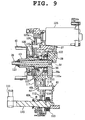
- the centrifugal clutch mechanism 17 is of a wet, multiple plate type, as mainly shown in FIGs. 12 to 15 , constituted in rough description as follows:
- the boss 83b of the outer clutch 83 is spline-fitted onto the transmission shaft 47 to rotate together.
- An inner clutch 84 is coaxially placed on the axially inner side of the outer clutch 83.
- the hub portion 84a of the inner clutch 84 is spline-fitted onto the primary reduction small gear 74 to rotate together.
- the primary reduction small gear 74 is rotatably attached to the transmission shaft 47.
- outer clutch plates 85 Plural number of outer clutch plates 85 are placed in the outer clutch 83 and on both sides of them are placed two pressing plates 86 and 86. Those components 85 and 86 are engaged with the outer clutch 83 so as to rotate together.
- Inner clutch plates 87 are placed among the outer clutch plates 85 and the pressing plates 86. The inner clutch plates 87 are engaged with the outer periphery of the inner clutch 84 so as to rotate together.
- a cam surface 83a is formed inside the outer clutch 83 and weights 88 are placed between the cam surface 83a and the pressing plates 86 located on the outer side.
- weights 88 are moved toward the left and radially outward of the outer clutch 83 in FIG. 12 (in the clutch engagement direction) to press and move the pressing plates 86 and make the outer and inner clutch plates 85 and 86 engage with each other.
- the upper half of FIG. 12 shows the centrifugal clutch mechanism 17 in the disengaged state and the lower half shows the engaged state.
- the centrifugal clutch mechanism 17 is provided with a clutch plate anti-stick mechanism 90.
- the clutch plate anti-stick mechanism 90 is constituted with plate springs 91 interposed between the outer clutch plates 85, and between the outer clutch plates 85 and the pressing plates 86 to urge the outer clutch plates 85 and the pressing plates 86 in the direction of parting from each other.
- pins 92 are passed through the inner clutch plates 87 at circumferential intervals.
- Coil springs 93 are placed among the inner clutch plates 87 to urge them in the direction of parting from each other.
- the weights 88 move radially outward by centrifugal force as the engine revolution increases, and their axial positions are determined with the cam surface 83a.
- the engine revolution exceeds a predetermined value by the opening operation of the throttle (not shown)
- the weights 88 press and move the pressing plates 86, and press together the outer and inner clutch plates 85 and 87.
- the engine revolution is transmitted from the transmission shaft 47 through the reduction gear mechanism 18 to the output shaft 48.
- the rotation of the output shaft 48 causes the rear wheel 7 to rotate through the drive sprocket 49 and the chain 50.
- the weights 88 move radially inward.
- pressing force of the weights 88 is released, the outer and inner clutch plates 85 and 87 make relative rotation, and the engine revolution is disengaged between the transmission shaft 47 and the output shaft 48.
- the outer clutch plates 85 and the pressing plates 86 separate from each other with the repulsive force of the plate springs 91, and the inner clutch plates 87 part from each other with the repulsive force of the coil springs 93.
- pins 92 prevent the inner clutch plates 87 from moving in the axial direction, the inner clutch plates 87 are prevented from tilting when the clutch is disengaged, which also helps prevent the clutch from dragging.
- the lubricant oil system is arranged that the lubricant oil in the lubricant oil chamber 95 formed at the bottom portion 22a of the crankcase 22 is drawn up and pressure-fed with an oil pump 96 to the bearings of the crankshaft 28, camshaft 31, and other sliding parts to be lubricated, and allowed to freely fall and return to the lubricant oil chamber 95.
- the lubricant oil chamber 95 is positioned below the crank chamber 37 and provided with a swell portion 22b swelling toward the right side of the engine.
- the swell portion 22b is located below the transmission case 45, and between the swell portion 22b and the transmission case 45 is formed a gap (c).
- the space (a) between the transmission case 45 and the crank case 22 connects to the outside through the gap (c).
- the center (D) of the lubricant oil chamber 95 as a whole is disposed to be shifted toward the right side in the crankshaft direction:
- the inside wall 22c of the lubricant oil chamber 95 constituting the side wall opposite the transmission case is approximately in the same position, in the crankshaft direction, as the left journal support wall 40c for supporting the left side journal bearing 35 of the crankshaft 28.
- the oil pump 96 is placed on the inner surface 22c of the lubricant oil chamber 95.
- the oil pump 96 is positioned between the left journal support wall 40c and the generator 42, in the crankshaft direction.
- the oil pump 96 comprises a pump shaft 96a supported with a housing 97 having a suction port 97a and a discharge port 97b, and a pump gear 98 attached to the outside end portion of the pump shaft 96a.
- a suction passage 40f communicating with the suction port 97a is formed in the first case 40 and made open through an oil strainer 99 at the bottom surface in the lubricant oil chamber 95.
- a lubricant oil supply passage 40g communicating with the discharge port 97b is formed also in the first case 40 and made to communicate through an oil filter 100 with a main supply passage 44a formed in the generator case 44. The downstream end of the main supply passage 44a is connected to an oil chamber 44c communicating with the left end surface of the crankshaft 28.
- An oil passage 28e communicating with the oil chamber 44c is formed axially in the crankshaft 28 and made open, through a branch passage 29a formed in the crankpin 29, to a connecting bearing portion 101 where the crankpin 29 and the connecting rod 27 are interconnected.
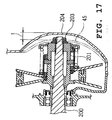
- the oil filter 100 is constituted that an element 100b is housed in a filter chamber 100a disposed in the generator case 44 in a depressed manner and the filter chamber 100a is removably covered with a filter cover 100c.
- the filter chamber 100a is formed to overlap, in the crankshaft direction, with the generator 42 and the filter cover 100c is approximately in the same position, in the crankshaft direction, with the generator case 44.
- the filter chamber 100a is located below the first plane C including the axes of the crankshaft 28 and the transmission shaft 47 and between the second plane E orthogonal to the first plane C and includes the axis of the crankshaft 28, and the third plane F orthogonal to the first plane C and includes the axis of the transmission shaft 47.
- the filter chamber 100a is located below the crank chamber 37 and, as seen in the crankshaft direction, overlaps in part with the lubricant oil chamber 95.
- the clutch mechanism 17 is mounted on the transmission shaft 47 so as to overlap, at least in part, in the crankshaft direction, with the right crank arm 28b of the crankshaft 28.
- the axis of the filter chamber 100a is disposed adjacent to, more particularly, slightly below the bottom edge of the clutch mechanism 17 and parts to the left side, in the crankshaft direction, from the clutch mechanism 17.
- a reference numeral 44d shows an oil level check window for checking if the lubricant oil level is between MAX to MIN.
- the lubricant oil drawn up with the oil pump 96 is pressure-fed to the oil passage 28e through the supply passage 40g, the oil filter 100, and the main supply passage 44a and then from the oil passage 28e to the connecting bearing portion 101 through the branch passage 29a.
- the lubricant oil supplied to the connecting bearing portion 101 is spread with oil feeding pressure and centrifugal force of the crankshaft 28 within the crank chamber 37. Part of the spread lubricant oil enters the reduction chamber 39 to lubricate the secondary reduction small gear 52a and secondary reduction large gear 48a and falls into the lubricant oil chamber 95.
- the free space under the transmission case 45 is effectively used to increase the amount of lubricant oil in the lubricant oil chamber 95. Therefore, unlike the arrangement in which the depth of the case bottom is increased to secure the amount of lubricant oil, the height of the engine 2 does not need to be increased.
- this embodiment is arranged that the V-belt is made of a resin member and the transmission case 45 is made to be independent of the crankcase 22, heat resistance and durability of the V-belt are enhanced in comparison with an arrangement using a rubber belt, and thermal effect from the engine is restricted. As a result, it is possible to reduce the diameters of the drive pulley 55 and the driven pulley 56, and the size of the transmission case 45. This makes it possible to produce a free space under the transmission case 45 and accordingly form the swell portion, and increase the lubricant oil capacity.
- the filter chamber 100a is disposed in a depressed manner on the side surface of the generator case 44 opposite the transmission case 45 so as to overlap, in the crankshaft direction, with the generator 42, it is possible to dispose the oil filter 100 without protruding from the engine case 44 and to eliminate the problem of engine width increase due to the disposition of the oil filter 100 while the transmission case 45 is provided.
- the filter chamber 100a is located below the first plane C including the axes of the crankshaft 28 and the transmission shaft 47 and between the second plane E orthogonal to the first plane C and includes the axis of the crankshaft 28, and the third plane F orthogonal to the first plane C and includes the axis of the transmission shaft 47. Therefore, it is possible to secure a space for the filter chamber 100a to be disposed in a depressed manner on the generator case 44 opposite the transmission case 45 and to dispose the oil filter 100 without protruding from the generator case 44.
- the clutch mechanism 17 is placed from the generator case 44 toward the inner side in the crankshaft direction, and since the filter chamber 100a is placed so that the axis is located below the bottom edge of the clutch mechanism 17, it is possible to more reliably secure a space for disposing the filter chamber 100a and to dispose the oil filter 100 without protruding from the side surface of the generator case 44.
- the exhaust pipe 24 extends toward the rear of the vehicle body along the transmission case 45 and the lateral side of the lubricant oil chamber 95, it is possible to place the exhaust pipe 24 without interfering with the filter chamber 100a placed opposite the transmission case 45 and to ensure ease of maintenance including replacement of the oil filter 100.
- the lubricant oil chamber 95 is disposed below the crank chamber and shifted to the side of the transmission case 45, it is possible to place the filter chamber 100a overlapping with at least a part of the lubricant oil chamber 95, as seen in the crankshaft direction, and to secure a space for disposing the filter chamber 100a.
- part of the centrifugal clutch mechanism 17 is located in the area, as seen in the direction at right angles to the crankshaft, where lubricant oil is spread from the connecting bearing portion 101 of the connecting rod 27 and the crankpin 29. That is to say, the outer and inner clutch plates 85 and 87 of the centrifugal clutch mechanism 17 are located to face the crank chamber 37.
- a lead-in opening 103 for leading the lubricant oil spread from the connecting bearing portion 101 into the clutch chamber 38 is formed in the second peripheral wall 41 a that defines the crank chamber 37 and the clutch chamber 38.
- the clutch support wall portion 41 d is integrally formed with a guide portion 104 extending to the inward of the clutch chamber 38.
- the guide portion 104 is located on the extension of the line interconnecting the crankshaft 28 and the transmission shaft 47 and comprises a lubricant oil receiving portion 104a extending vertically so as to generally face the lead-in opening 103 and a guide portion 104b continuously extending in an arcuate shape from the lower end of the lubricant oil receiving portion 104a toward the underside of the transmission shaft 47.
- the guide portion 104b is located as inserted into the truncated-cone-shaped boss portion of the inner clutch 84.
- the lubricant oil entering through the lead-in opening 103 is received with the guide portion 104, guided more to the inner side than to the outer side of the centrifugal clutch mechanism 17, supplied by centrifugal force of the centrifugal clutch mechanism 17 between the outer and inner clutch plates 85 and 87, and supplied to the engaging area of the primary reduction large and small gears 75 and 74 (as shown with arrows in FIGs. 3 and 7 ).
- the centrifugal clutch mechanism lubricating structure of the present embodiment is arranged that the lubricant oil supplied to the connecting bearing portion 101 of the crankpin 29 and the connecting rod big end 27a is led to the centrifugal clutch mechanism 17. Therefore, it is possible to supply a large amount of lubricant oil that is spread from the connecting bearing portion 101 to the centrifugal clutch mechanism 17 to prevent the outer and inner clutch plates 85 and 87 from being seized by heat without employing a special lubrication oil passage.
- This embodiment makes it possible to lead the lubricant oil from the crank chamber 37 effectively into the clutch chamber 38 with a very simple constitution since the centrifugal clutch mechanism 17 is located, as seen in the direction at right angles to the crankshaft, in the area over which the lubricant oil from the connecting bearing portion 101 is spread, and the lead-in opening 103 for permitting the entry of lubricant oil is formed in the second peripheral wall 41 a that defines the clutch chamber 38 and the crank chamber 37.
- This embodiment is arranged that the clutch support wall portion 41 d is integrally formed with a guide portion 104 extending to the inward of the clutch chamber 38.
- the guide portion 104 is located on the extension of the line interconnecting the crankshaft 28 and the transmission shaft 47 and comprises a lubricant oil receiving portion 104a extending vertically so as to generally face the lead-in opening 103 and a guide portion 104b continuously extending in an arcuate shape from the lower end of the lubricant oil receiving portion 104a toward the underside of the transmission shaft 47. Therefore, lubricant oil is supplied more securely to the outer and inner clutch plates 85 and 87.
- a kick shaft 110 is placed parallel to and nearly vertically below the output shaft 48.
- the kick shaft 110 as seen in the crankshaft direction, is located to overlap with at least a part of both the clutch mechanism 17 and the driven pulley 56.
- the kick shaft 110 is journal-supported at the portion inside the drive sprocket 49 with the boss portion 40h of the first case 40 and at the outside portion with the boss portion 44b integrally formed with the generator case 44.
- a kick arm 111 is attached to the outside end portion of the kick shaft 110 and a kick gear 112 is spline-fitted to be axially slidable onto the inside end portion of the kick shaft 110
- the kick gear 112 is located inside the first case 40.
- a return spring 113 is wound around the inside end portion of the kick shaft 110 to urge the kick shaft 110 toward the starting position.
- a main intermediate shaft 114 and a sub-intermediate shaft 115 are placed between the kick shaft 110 and the crankshaft 28 and parallel to the kick shaft 110.
- the main intermediate shaft 114 extends between the first and second cases 40 and 41 and journal-supported with them.
- a main intermediate gear 116 capable of engaging with the kick gear 112 is attached to the main intermediate shaft 114.
- the sub-intermediate shaft 115 is journal-supported with the bearing portion 40j formed in the first case 40.
- the inside and outside ends of the sub-intermediate shaft 115 project respectively inward and outward of the first case 40.
- a first intermediate gear 115a for engaging with the main intermediate gear 116 is integrally formed inside the case of the sub-intermediate shaft 115 and a second intermediate gear 117 is attached outside the case.
- the second intermediate gear 117 engages with a first crank gear 121 which will be described later.
- the series of kick gears for transmitting rotation of the kick shaft 110 to the crankshaft 28 is constituted with the kick gear 112, the main intermediate gear 116, the first intermediate gear 115a, and the second intermediate gear 117.
- the series of kick gears is located between the first support wall portion 40b for supporting the left journal bearing 35 and the generator 42.
- the kick gear 112, the main intermediate gear 116, and the first intermediate gear 115a are located in a position that communicates with the lubricant oil chamber 95 inside the first case 40.
- the second intermediate gear 117, the first crank gear 121, and the cam sprocket 122 are located outside the first case 40.
- the kick shaft 110 rotates, the kick gear 112 moves axially and engages with the main intermediate gear 116 to transmit the rotation to the first crank gear 121 through the first and second intermediate gears 115a and 117 and rotate the crankshaft 28.
- crankshaft 28 between the left journal bearing 35 and the sleeve 43 of the generator 42 is provided with a one-way clutch 120, the first crank gear 121, and a cam sprocket 122 in the order from outer side.
- the one-way clutch 120 is provided with a starting gear 120a connected through an idler gear 124 to a drive gear 125a of a starter motor 125.
- the starter motor 125 with its motor axis parallel to the crankshaft 28, is secured to the front wall of the crankcase 22.
- the series of starting gears for transmitting rotation of the starter motor 125 to the crankshaft 28 is constituted with the drive gear 125a, the idler gear 124, and the starting gear 120a.
- the series of starting gears is located between the support wall for supporting the right journal bearing 35 and the generator 42.
- the kick mechanism of this embodiment is arranged that the kick gear 112, the main intermediate gear 116, and the first intermediate gear 115a are located in the position that communicates with the lubricant oil chamber 95, engaging parts of those gears are sufficiently lubricated.
- the sub-intermediate shaft 115 is made to pass through the first case 40 from the inside to the outside to transmit the rotation of the kick shaft 110 from the inner side of the sub-intermediate shaft 115 to the outer side, and from the second intermediate gear 117 on the outer side to the crankshaft 28 through the first crank gear 121, it is possible to locate the first crank gear 121 on the outer side than the crank journal portion 28c, to reduce the distance between the crankshaft bearings 35 and 36, and to journal-support the crankshaft 28 while reducing the bending moment due to the connecting rod 27. It is also possible to secure the layout space for the cam sprocket 122 and the second crank gear 127 to facilitate the layout around the crankshaft.
- this embodiment is arranged that the kick shaft 110 is located nearly vertically below the output shaft 48, the kick arm 111 is easy to kick down and the size of the engine 2 can be reduced in the longitudinal direction of the vehicle.
- Part of the kick shaft 110 on the inner side in the vehicle width direction of the rear wheel drive sprocket 49 is journal-supported with the first clutch support wall portion 40d, part of it on the outer side in the vehicle width direction is journal-supported with the generator case 44, and the kick arm 111 is attached to part of the kick shaft 111 projecting to the outer side of the kick shaft 110 than the generator case 44. Therefore, it is possible to place the kick shaft 110 and the kick arm 111 in positions for kicking down without interfering with the rear wheel drive sprocket 49.
- the kick shaft 110 As shown in FIG. 4 , the kick shaft 110, as seen in the crankshaft direction, is located within the axial projection area of the transmission case 45, more particularly, within the axial projection areas of the driven sprocket 56 and the centrifugal clutch mechanism 17. That is to say, it is located nearly just below the driven pulley 56.
- the kick shaft 110 is placed on the opposite side of the transmission case 45 as described above, a space for placing the kick shaft need not be secured in the transmission case 45, so that it is possible to place the drive pulley 55 and the driven pulley 56 of the CVT 16 close to each other to the extent that only a small gap (b) (see FIG 3 ) exists and accordingly the dimension of the engine 2 is reduced in the longitudinal direction of the vehicle.
- the kick shaft 110 is placed within the area of projection in the crankshaft direction of the crankcase 45, it is possible to place the kick shaft 110 in a position that is near the crankshaft 28 and easy to kick down.
- this embodiment is arranged that the centrifugal clutch mechanism 17 is placed in the vicinity on the inner side in the crankshaft direction of the driven pulley 56, and since the kick shaft 110 is placed in a position that is within the axial projection area of the centrifugal clutch mechanism 17 and nearly vertically below the transmission shaft 47, it is possible to utilize a free space within the projection area of the centrifugal clutch mechanism to locate the kick shaft 110 in the optimum position for kicking down and to reduce the size of the engine 2 in the vehicle's longitudinal direction.
- a balancer shaft 129 is placed parallel to and rearward above the crankshaft 28.
- the balancer shaft 129 is journal-supported through balancer shaft bearings 130 and 131 with the first and second cases 40 and 41.
- the left end of the balancer shaft 129 projects outside the first case 40 and is connected to a balancer gear 132.
- a damping member 133 is attached to the inside circumferential surface of the balancer gear 132.
- the left and right crank arms 28a and 28b of the crankshaft 28 are located inside the balancer bearings 130 and 131, and the balancer weight 129a of the balancer shaft 129 is placed between the left and right crank arms 28a and 28b and near the crankshaft 28 so as to be superposed on the rotary locus of the crankpin 29. This makes the area around the balancer shaft compact.
- the crankshaft 28 is press-fit into the first crank gear (first drive gear) 121 to which is attached a second crank gear (second drive gear) 127 to rotate together.
- the balancer gear (second driven gear) 132 engages with the second crank gear 127. That is to say, inside circumferential teeth 127a are formed on the inside circumferential surface of the second crank gear 127, with the inside circumferential teeth 127a engaging with the outside circumferential teeth 121a of the first crank gear 121 (see FIG. 6 ).
- the series of balancer gears for transmitting rotation of the crankshaft 28 to the balancer gear 132 is constituted with the first crank gear 121, the second crank gear 127, and the balancer gear 132.
- the series of balancer gears is located between the support wall for supporting the left journal bearing 35 and the generator 42.
- the pump gear (first driven gear) 98 is connected through the second intermediate gear 117 to the first crank gear 121.
- the series of pump gears for transmitting rotation of the crankshaft 28 to the oil pump 96 is constituted with the first crank gear 121, the second intermediate gear 117, and the pump gear 98.
- the series of pump gears is located between the support wall for supporting the left journal bearing 35 and the generator 42.
- the one-way clutch 120, the first crank gear 121, and the cam sprocket 122 attached to the crankshaft 28 are held to be axially immovable between the sleeve 43 and the journal bearing 35 as a nut 123 is screwed and tightened to the left end portion of the crankshaft 28.
- This embodiment is arranged that the second intermediate gear 117 engaging with the first crank gear 121 is used both for transmitting the rotation of the kick shaft 110 to the crankshaft 28 and for transmitting the rotation of the crankshaft 28 to the gear pump 98, so that it is possible to reduce the crankshaft length accordingly and make the engine compact in width.
- first crank gear 121 press-fitted into the crankshaft 28 engages with the inside circumferential teeth 127a of the second crank gear 127 and with the second intermediate gear 117, it is possible to secure a sufficient length of the first crank gear 121 to be press-fitted into the crankshaft 28 and reliably transmit the rotation of the crankshaft 28 to the pump gear 98 and the balancer gear 132.
- the outside circumferential teeth 121 a of the first crank gear 121 engage with the inside circumferential teeth 127a of the second crank gear 127 so that the second crank gear 127 can be easily assembled, and removed for the purpose of maintenance. That is, the second crank gear 127 can be easily removed from the first crank gear 121 after removing the nut 123 from the crankshaft 28 and taking out the sleeve 43 and the one-way clutch 121.
- the positioning arrangement of various shafts of the engine 2 is as follows.
- the transmission shaft 47 and the output shaft 48 are behind and on the same level with the crankshaft 28.
- the balancer shaft 129 and the reduction shaft 52 are placed above the first plane C that includes the axes of the crankshaft 28 and the output shaft 48.
- the kick shaft 110, the pump shaft 96a, and the main and sub-intermediate shafts 114 and 115 are placed above the first plane C.
- the kick shaft 110 is placed nearly vertically below the output shaft 48.
- the pump shaft 96a is placed nearly vertically below the balancer shaft 129.
- the main and sub-intermediate shafts 114, 115 are placed on the line interconnecting the crankshaft 28 and the kick shaft 110.
- This embodiment is arranged that the balancer shaft 129 is placed above the first plane C that includes the axes of the crankshaft 28 and the output shaft 48, and the kick shaft 110 and the pump shaft 96a of the oil pump 96 are below the first plane C, so that those components are well balanced in upper and lower positions to avoid increase in the engine size. That is, a locating space is formed behind the cylinder bore and above the first plane C, and the balancer shaft 129 is located in the space. Since the balancer shaft 129 rotates with a large rotation locus of the weight 129a, if the weight were dipped in lubricant oil, a large amount of horsepower would be lost as lubricant oil is stirred.
- the balancer shaft 129 does not stir lubricant oil.
- This embodiment is also arranged that the reduction shaft 52 is placed by utilizing the free space located above the first plane C and between the balancer shaft 129 and the output shaft 48. Although the reduction shaft 52 is placed in a high position that is less likely to be spread with lubricant oil, since lubricant oil spread from the connecting bearing portion 101 of the connecting rod of the crankshaft 28 is supplied to the reduction gear 75 and other parts, no problem occurs as to poor lubrication.
- the kick shaft 110 is placed nearly vertically below the output shaft 48, it is possible to reduce the longitudinal size of the engine 2 and place the kick shaft 110 in a position where it is easy to kick down.
- the lubricant oil chamber 95 is disposed to be shifted to the side of the transmission case 45 and the series of kick gears, pump gears, starting gears, and balancer gears are shifted and disposed to the opposite side of the transmission case 45 from the lubricant oil chamber 95 of the engine case, more particularly, it is placed between the first support wall portion 40b for supporting the left crank journal portion and the generator 42. Therefore, it is possible to dispose the series of gears by effectively using the space between the generator 42 and the first support wall 40b, to secure a space for disposing the series of gears, and to avoid engine width increase.
- the lubricant oil chamber 95 is located in the area from the lower part of the crank chamber to the lower part of the transmission case, it is possible to dispose and shift the lubricant oil chamber 95 while securing required capacity of the lubricant oil chamber 95, and to secure a space for disposing the series of,gears.
- the series of gears are disposed along the first support wall 40b for supporting the crank journal portion or between the support wall 40b and the generator 42, it is possible to dispose the filter chamber 100a on the side surface of the generator 42 opposite the transmission case and in an overlapping position with at least a part of any of the series of gears, and to dispose the oil filter 100 without the engine size increase in longitudinal and lateral directions.
- the engine is arranged that the filter chamber is disposed in a depressed manner on the side surface of the engine case opposite to the transmission case, and that the filter chamber overlaps, in the crankshaft direction, at least in part with the generator. Therefore, it is possible to dispose the oil filter without protruding from the engine case and to eliminate the problem of engine width increase due to the disposition of the oil filter while the transmission case is provided.
- the filter chamber is located below the first plane including the axes of the crankshaft and the transmission shaft. More preferably, it is arranged that the filter chamber is located between the second plane orthogonal to the first plane and including the axis of the crankshaft and the third plane orthogonal to the first plane and including the axis of the transmission shaft. Therefore, it is possible to secure a space in the engine case for disposing the filter chamber in a depressed manner opposite to the transmission case, to dispose the oil filter without protruding from the engine case, and to avoid engine width increase.
- the clutch mechanism is attached to overlap at least in part with the crank arm of the crankshaft in the crankshaft direction, that is, the clutch mechanism is placed in the engine case from the opposite side of the transmission case toward the inner side in the crankshaft direction, and that the axis of the filter chamber is located adjacent to the bottom edge of the clutch mechanism. Therefore, it is possible to more reliably secure a space for disposing the filter chamber, to dispose the oil filter without protruding from the side surface of the engine case, and to avoid engine width increase.
- the exhaust pipe extends toward the rear of the vehicle body along the lower part of the transmission case and the lateral side of the engine case bottom. Therefore, it is possible to place the exhaust pipe without interfering with the filter chamber placed opposite to the transmission case and to ensure ease of maintenance including replacement of the oil filter.
- the lubricant oil chamber is disposed below the crank chamber and shifted to the side of the transmission case. Therefore, it is possible to place the filter chamber overlapping with at least a part of the lubricant oil chamber, as seen in the crankshaft direction, to secure a space for disposing the filter chamber, and to place the oil filter without protruding from the engine case.
- the kick shaft is placed on the opposite side of the transmission case, below the transmission shaft and the output shaft, and in order to overlap with at least one of the driven pulley or the clutch mechanism.
- the kick shaft is placed to overlap with both the driven pulley and the clutch mechanism. Therefore, it is possible to reduce the distance between axes of the drive pulley and the driven pulley, and accordingly, the longitudinal dimension of the engine. Further, since the kick shaft is placed on the opposite side of the transmission case, it is possible to place the kick shaft in a position that is near the crankshaft and easy to kick down.
- the kick gear and the first intermediate gear are disposed in the inner side of the support wall portion for supporting the crank journal portion on the opposite side of the transmission case, and that the second intermediate gear and the crank gear are disposed on the outer side of the support wall portion. Therefore, it is possible to dispose the crank gear immediately adjacent to the outer side of the crank journal portion and to avoid engine width increase due to the disposition of the series of kick gears while the transmission case is provided.
- the lubricant oil chamber is disposed to be shifted to the side of the transmission case, and that at least one of the series of kick gears, pump gears, starting gears, and balancer gears is disposed to be shifted to the opposite side of the transmission case from the lubricant oil chamber of the engine case. Therefore, it is possible to secure a space in the engine case on the opposite side of the transmission case for disposing the series of gears due to the shifted disposition of the lubricant oil chamber, and to avoid engine width increase.
- the side wall of the lubricant oil chamber on the opposite side of the transmission case is constituted of the support wall portion for supporting the journal portion on the opposite side of the transmission case, and that at least one of the series of kick gears, pump gears, starting gears, and balancer gears is disposed along the support wall portion. Therefore, it is possible to more reliably secure a space in the engine case on the opposite side of the transmission case for disposing the series of gears due to the shifted disposition of the lubricant oil chamber, and to avoid engine width increase.
- the lubricant oil chamber is located in the area from the lower part of the crank chamber of the engine case to the lower part of the transmission case. Therefore, it is possible to dispose the lubricant oil chamber to be shifted while securing required capacity of the lubricant oil chamber, accordingly to secure a space for disposing the series of gears, and to avoid engine width increase.
- the generator is attached to the crankshaft at the opposite end of the transmission case, and that at least one of the series of kick gears, pump gears, starting gears, and balancer gears passes between the generator and the support wall portion for supporting the opposite side and is connected to the crankshaft. Therefore, it is possible to dispose the series of gears by effectively using the space between the generator and the support wall portion and to avoid increasing longitudinal and lateral dimensions of the engine.
- the series of gears are disposed along the support wall for supporting the crank journal portion or between the support wall and the generator, and that the filter chamber is disposed in a depressed manner on the side surface of the engine case opposite to the transmission case so as to overlap with the generator in the crankshaft direction.
- the filter chamber is placed to overlap with at least a part of any of the series of gears, as seen in the crankshaft direction. Therefore, it is possible, in case that the engine comprises a transmission case on one side of the engine case, to dispose the filter chamber in a depressed manner without interfering with the series of gears placed opposite to the transmission case, and to dispose the oil filter without engine width increase.
- the kick gear and the first intermediate gear are disposed in the inner side of the support wall portion for supporting the opposite side, and that the second intermediate gear and the crank gear are disposed on the outer side of the support wall portion for supporting the opposite side. Therefore, it is possible to dispose the crank gear immediately adjacent to the outer side of the crank journal portion and to avoid engine width increase due to the disposition of the series of kick gears while the transmission case is provided.
- the lubricant oil pump is attached to the portion constituting the side wall of the lubricant oil chamber shifted to the side of the transmission case. Therefore, it is possible to place the lubricant oil pump toward the inner side in the crankshaft direction without any difficulty and to avoid engine width increase.
- an engine preferably comprises a V-belt type continuously variable transmission on one side of an engine case, said CVT being provided with and housing in a transmission case a drive pulley attached to one end of a crankshaft, a driven pulley attached to one end of a transmission shaft parallel to said crankshaft, and a V-belt routed around the pulleys, and said engine case supporting said crankshaft and transmission shaft in a rotatable manner; and a generator attached to the opposite end of said crankshaft in said engine case.
- a filter chamber is provided in the opposite side surface of said transmission case of said engine case in a depressed manner so as to overlap with at least a part of said generator in the crankshaft direction, and an oil filter for filtering lubricating oil is disposed in said filter chamber.
- said filter chamber is located below the first plane including the axes of said crankshaft and said transmission shaft.
- said filter chamber is located between the second plane orthogonal to said first plane and including the axis of said crankshaft and the third plane orthogonal to said first plane and including the axis of said transmission shaft.
- a clutch mechanism is attached to said transmission shaft, said clutch mechanism overlapping at least in part with a crank arm of said crankshaft in the crankshaft direction, the axis of said filter chamber is located adjacent to the bottom edge of said clutch mechanism, and said filter chamber is separated from said clutch mechanism in the crankshaft direction.
- an exhaust pipe is connected to an exhaust opening of a cylinder connected to said engine case and passing below said transmission case and along the side of the bottom of said engine case to extend in the backward direction of the vehicle.
- a lubricant oil chamber for collecting the lubricating oil is disposed below a crank chamber and shifted to the side of said transmission case, and at least a part of said filter chamber overlaps with said lubricant oil chamber as seen in the crankshaft direction.
- an engine as described above comprises a kick shaft which is placed on the opposite side of said transmission case and parallel to said crankshaft and positioned, as seen in the crankshaft direction, below said transmission shaft and an output shaft in order to overlap with at least one of said driven pulley or said clutch mechanism.
- said transmission shaft and said output shaft are coaxially disposed, and said kick shaft is located approximately directly below said output shaft and overlaps with both said driven pulley and said clutch mechanism.
- the engine is provided with a kick gear attached to said kick shaft which is capable of engaging with the first intermediate gear attached to one end of an intermediate shaft, the second intermediate gear attached to the opposite end of said intermediate shaft is capable of engaging with a crank gear attached to said crankshaft, said kick gear and said first intermediate gear are disposed in the inner side of a support wall portion for supporting a journal portion on the opposite side of said transmission case of said crankshaft, and said second intermediate gear and said crank gear are disposed on the outer side of said support wall portion.
- an engine as described above is configured that the center of said lubricant oil chamber for collecting the lubricating oil in the crankshaft direction is disposed to be shifted to the side of said transmission case from the engine center line passing through a cylinder axis line, and at least one of a series of kick gears for transmitting the rotation of said kick shaft to said crankshaft, a series of pump gears for transmitting the rotation of said crankshaft to a lubricant oil pump, a series of starting gears for transmitting the rotation of a starter to said crankshaft, and a series of balancer gears for transmitting the rotation of said crankshaft to a balancer shaft is disposed to be shifted to the opposite side of said transmission case from said lubricant oil chamber of said engine case.
- the side wall of said lubricant oil chamber on the opposite side of said transmission case is constituted of a support wall portion for supporting a journal portion on the opposite side of said transmission case of said crankshaft and at least one of said series of kick gears, said series of pump gears, said series of starting gears, and said series of balancer gears is disposed along said support wall portion for supporting the opposite side.
- said lubricant oil chamber is located in the area from the lower part of said crank chamber of said engine case to the lower part of said transmission case.
- said filter chamber is disposed in a depressed manner on the side surface of said engine case opposite to said transmission case so as to overlap at least in part with said generator attached to the end of said crankshaft opposite to said transmission case, and said oil filter for filtering the lubricant oil is provided in said filter chamber.
- said series of kick gears is constituted that the kick gear attached to the kick shaft is capable of engaging with the first intermediate gear attached to one end of an intermediate shaft, the second intermediate gear attached on the opposite end of said intermediate shaft is capable of engaging with said crank gear attached to said crankshaft, said kick gear and said first intermediate gear are disposed in the inner side of said support wall portion, and said second intermediate gear and said crank gear are disposed on the outer side of said support wall portion.
- said series of pump gears is constituted to transmit the rotation of said crank gear attached between said support wall portion of said crankshaft and said generator to the pump gear through an intermediate gear, and said pump gears are attached to a rotational shaft of said lubricant oil pump attached to the portion of said support wall portion constituting the side wall of said lubricant oil chamber.
- an engine comprises: a V-belt type continuously variable transmission on one side of an engine case, said CVT being provided with and housing in a transmission case a drive pulley attached to one end of a crankshaft, a driven pulley attached to one end of a transmission shaft parallel to said crankshaft, a V-belt routed around the pulleys, said engine case supporting said crankshaft and transmission shaft in a rotatable manner, and a generator attached to the opposite end of said crankshaft in said engine case; in which a filter chamber is disposed in the opposite side surface of said transmission case of said engine case in a depressed manner so as to overlap with at least a part of said generator in the crankshaft direction, and an oil filter for filtering lubricating oil is disposed in said filter chamber.
- the engine with a V-belt type continuously variable transmission (16) is positioned on one side of an engine case (15), wherein a filter chamber (100a) housing a lubricating oil filter (100b) is provided at a side of said engine case (15) which is opposite to the side of said continuously variable transmission (16), said filter chamber (100a) overlapping with at least a part of a generator (42) of said engine (2) in a crankshaft direction.
- said continuously variable transmission (16) is provided with and houses in a transmission case (45) a drive pulley (55) attached to one end of a crankshaft (28) of the engine (2), a driven pulley (56) attached to one end of a transmission shaft (47) being parallel to said crankshaft (28), and a V-belt (57) routed around the drive and driven pulleys (55,56), and/or in that said generator (42) is attached to the end of said crankshaft (28) opposite to the side to which said continuously variable transmission (16) is attached, and/or in that said filter chamber (100a) is positioned in a depressed manner overlapping with at least a part of a lubricating oil chamber (95) of the engine (2) when viewed in the crankshaft direction.
- said filter chamber (100a) is located below a first plane (C) which includes an axis of a crankshaft (28) of the engine (2) and an axis of a transmission shaft (48) of the continuously variable transmission (16), wherein preferably said filter chamber (100a) is located between a second plane (E) orthogonal to said first plane (C) and including the axis of said crankshaft (28) and a third plane (F) orthogonal to said first plane (C) and including the axis of said transmission shaft (48).
- a clutch mechanism (17) is attached to a transmission shaft (47) of said continuously variable transmission (16), wherein said clutch mechanism (17) overlaps at least in part with a crank arm (28a,28b) of a crankshaft (28) of the engine (2) in the crankshaft direction, wherein an axis of said filter chamber (100a) is located adjacent to a bottom edge of said clutch mechanism (17), and/or wherein said filter chamber (100a) is separated from said clutch mechanism (17) in the crankshaft direction.
- an exhaust pipe (24) is connected to an exhaust opening (20c) of a cylinder which is oriented in a forward direction of said engine case (15), the exhaust pipe (24) being connected to the engine case (15) and passing below said transmission case (45) and/or along a side of a bottom of said engine case (15) in a backward direction of the engine case (15).
- a lubricant oil chamber (95) for collecting lubricating oil is disposed below a crank chamber (37) and offset to the side of the engine case (15) at which said continuously variable transmission (16) is positioned, wherein at least a part of said filter chamber (100a) overlaps with said lubricant oil chamber (95) as seen in the crankshaft direction.
- the engine in particular with a V-belt type continuously variable transmission (16) is positioned on one side of an engine case (15), wherein a kick shaft (110) is placed at a side of said engine case (15) which is opposite to the side at which said continuously variable transmission (16) is positioned, and/or in that the kick shaft (110) is placed, as seen in a crankshaft direction, below a transmission shaft (47) of said continuously variable transmission (16) and/or an output shaft (48) of a clutch mechanism (17) connected to said transmission shaft (48).
- a kick gear (112) attached to said kick shaft (110) is capable of engaging with a first intermediate gear (115a) attached to one end of an intermediate shaft (115), a second intermediate gear (117) attached to an opposite end of said intermediate shaft (115) is capable of engaging with a crank gear (121) attached to said crankshaft (28), in that said kick gear (112) and said first intermediate gear (115a) are disposed in an inner side of a support wall portion (40c) for supporting a journal portion of said crankshaft (28) on the side opposite the side of said continuously variable transmission (16), and in that said second intermediate gear (117) and said crank gear (121) are disposed on the outer side of said support wall portion (40c).
- the engine with a V-belt type continuously variable transmission (16) is positioned on one side of an engine case (15), wherein a center (D) of a lubricant oil chamber (95) for collecting lubricating oil is offset in a crankshaft direction to the side of said continuously variable transmission (16) with respect to an engine center line (A) passing through a cylinder axis of the engine (2), and/or in that at least one of: a series of kick gears (112, 115a, 116, 117, 121) for transmitting the rotation of a kick shaft (110) to a crankshaft (28) of the engine (2), a series of pump gears (98,117,121) for transmitting the rotation of said crankshaft (28) to a lubricant oil pump (96), a series of starting gears (120a,124,125a) for transmitting the rotation of a starter (125) to said crankshaft (28), and/ or a series of balancer gears (121,127,132) for
- a side wall (22c) of said lubricant oil chamber (95) at the side of the engine case (15) opposite to the continuously variable transmission (16) is constituted of a support wall portion (40c) supporting a journal portion of said crankshaft (28) on the side of the engine case (15) opposite to said continuously variable transmission (16), and/or in that at least one of said series of kick gears (112, 115a, 116, 117, 121), said series of pump gears (98, 117, 121), said series of starting gears (120a,124,125a), and said series of balancer gears (121,127,132) is disposed along said support wall portion (40c).
- said lubricant oil chamber (95) is located in an area reaching from a lower part of a crank chamber (37) of said engine case (15) to a lower part of said transmission case (45).
- a generator (42) is attached to an end of said crankshaft (28) which is opposite to said side of said continuously variable transmission (16), and/or in that at least one of said series of kick gears (112, 115a, 116, 117, 121), said series of pump gears (98, 117, 121), series of starting gears (120a,124,125a), and series of balancer gears (121,127,132) passes between said generator (42) and said support wall portion (40c) and is connected to said crankshaft (28).
- a filter chamber (110a) is disposed in a depressed manner on the side surface of said engine case (15) opposite to said continuously variable transmission (16) overlapping at least in part with a generator (42) wherein preferably an oil filter (100b) for filtering lubricant oil is provided in said filter chamber (100a).
- At least a part of said filter chamber (95) overlaps with any one of said series of kick gears (112, 115a, 116, 117, 121), said series of pump gears (98, 117, 121), series of starting gears (120a,124,125a), and series of balancer gears (121,127,132) as seen in the crankshaft direction.
- said series of kick gears (112, 115a, 116, 117, 121) is constituted that a kick gear (112) attached to said kick shaft (110) is capable of engaging with a first intermediate gear (115a) attached to one end of an intermediate shaft (115), a second intermediate gear (117) attached to an opposite end of said intermediate shaft (115) is capable of engaging with a crank gear (121) attached to said crankshaft (28), said kick gear (112) and said first intermediate gear (115a) are disposed on an inner side of a support wall portion (40c), and said second intermediate gear (117) and said crank gear (121) are disposed on an outer side of said support wall portion (40c).
- said series of pump gears (98, 117, 121) is constituted to transmit a rotation of said crank gear (121) attached between a support wall portion (40c) of said crankshaft (28) and said generator (42) to a pump gear (98) via an intermediate gear (117), and/or said pump gear (98) is attached to a rotational shaft (96a) of said lubricant oil pump (96) attached to a portion of said support wall portion (40c) constituting the side wall (22c) of said lubricant oil chamber (95).
- a portion of said lubricant oil chamber (95), in particular a swell portion (22b) thereof, is arranged next to and/or reaches below a drive pulley (55) of said V-belt type continuously variable transmission (16), in particular when seen in a sectional view cutting through a pump shaft (96a) of a lubricating oil pump (96) and a crankshaft (28) of the engine.
- At least a portion of said lubricant oil chamber (95), in particular a swell portion (22b) thereof, is arranged next to and/or reaches below a driven pulley (56) of said V-belt type continuously variable transmission (16) and/or a clutch mechanism (17) and/or an output shaft (48), in particular when seen in a sectional view cutting through a filter chamber (100a) and an output shaft (48) of said V-belt type continuously variable transmission (16).
- At least a portion of said lubricant oil chamber (95), in particular a swell portion (22b) thereof, protruding outwardly from a side of the engine is arranged at a lower side of a transmission case (45) of said V-belt type continuously variable transmission (16), in particular when seen in a direction parallel with a crankshaft (28) of the engine.
- said lubricant oil chamber (95) is located below a first plane (C) which includes an axis of a crankshaft (28) of the engine (2) and an axis of an output shaft (48) of the continuously variable transmission (16), wherein preferably a main portion of said lubricant oil chamber (95) is located between a second plane (E) orthogonal to said first plane (C) and including the axis of said crankshaft (28) and a third plane (F) orthogonal to said first plane (C) and including the axis of said transmission shaft (48).
- the lubricant oil chamber (95) is disposed below a crank chamber (37) and/or shifted to the side of a transmission case (45)) of the continuously variable transmission (16), wherein preferably at least a part of the lubricant oil chamber (95) overlaps with a filter chamber (100a), as seen in the crankshaft direction.
- an exhaust pipe (24) extends along a transmission case (45)) of the continuously variable transmission (16) and a lateral side of the lubricant oil chamber (95a).
- a center (D) of said lubricant oil chamber (95) of is defined by a virtual plane cutting vertically through a crankshaft (28) of the engine and having an about equal distance to inner sides of side walls of the lubricant oil chamber (95), in particular when measured in a sectional view cutting through a pump shaft (96a) of a lubricating oil pump (96) and a crankshaft (28) of the engine, wherein preferably one of the side walls is an inside wall (22c) supporting the lubricating oil pump (96) and/or the other side wall is a side wall of a swell portion (22b) of said lubricant oil chamber (95).
- a vehicle in particular a motorcycle, is characterized by comprising an engine as described above.
Abstract
Description
- The present invention relates to an engine with a V-belt type continuously variable transmission positioned on one side of an engine case. Further, the invention relates to a vehicle, in particular a motorcycle.
- Some of the engines for use on motorcycles, for example, are provided with a CVT located on the axially outer side of the engine case and housing a V-belt type of CVT mechanism in a transmission case. In the engine described as above, since the transmission case occupies one side of the engine case, a problem of increased lateral and longitudinal engine dimensions may occur depending on the arrangement of engine accessories such as parts constituting the lubricating and starting systems.
- A conventional type of engine of the above kind with a V-belt type of CVT has, for example, an arrangement wherein an oil filter of the lubricating system is removably attached to and protruding on the side wall of the engine case, as it is disclosed in
JP-A-2002-021989 A - Besides, a conventional arrangement of a kick shaft constituting the starting system is known, wherein the kick shaft is located on the opposite side of the transmission case and between a drive and a driven pulley, as it is disclosed in
JP-A-H5-213262 - Additionally, the described arrangement of the kick shaft has a problem of increased lateral engine dimension, too, because the mechanism for transmitting the rotation of the kick shaft to the crankshaft is disposed on the outer side of the generator of the engine case in the lateral direction.
- It is, therefore, an object of the invention to provide an improved engine having a reduced size in longitudinal and lateral directions.
- It is further an object of the invention to provide a vehicle, in particular a motorcycle, having an improved engine.
- For an engine as described above, this object is solved in an inventive manner in that a filter chamber housing a lubricating oil filter is provided at a side of said engine case which is opposite to the side of said continuously variable transmission, said filter chamber overlapping with at least a part of a generator of said engine in a crankshaft direction, and/or in that a kick shaft is placed at a side of said engine case which is opposite to the side at which said continuously variable transmission is positioned, and/or in that the kick shaft is placed, as seen in a crankshaft direction, below a transmission shaft of said continuously variable transmission and/or an output shaft of a clutch mechanism connected to said transmission shaft, and/or in that a center of a lubricant oil chamber for collecting lubricating oil is offset in a crankshaft direction to the side of said continuously variable transmission with respect to an engine center line passing through a cylinder axis of the engine, and/or in that at least one of: a series of kick gears for transmitting the rotation of a kick shaft to a crankshaft of the engine, a series of pump gears for transmitting the rotation of said crankshaft to a lubricant oil pump, a series of starting gears for transmitting the rotation of a starter to said crankshaft, and/or a series of balancer gears for transmitting the rotation of said crankshaft to a balancer shaft, is offset in the crankshaft direction to a side of the engine case which is opposite to the side of said continuously variable transmission with respect to a center of a lubricant oil chamber and/or an engine center line.
- According to a preferred embodiment, said continuously variable transmission is provided with and houses in a transmission case a drive pulley attached to one end of a crankshaft of the engine, a driven pulley attached to one end of a transmission shaft being parallel to said crankshaft, and a V-belt routed around the drive and driven pulleys, and/or in that said generator is attached to the end of said crankshaft opposite to the side to which said continuously variable transmission is attached, and/or in that said filter chamber is positioned in a depressed manner overlapping with at least a part of a lubricating oil chamber of the engine when viewed in the crankshaft direction.
- According to another embodiment, said filter chamber is located below a first plane which includes an axis of a crankshaft of the engine and an axis of a transmission shaft of the continuously variable transmission, wherein preferably said filter chamber is located between a second plane orthogonal to said first plane and including the axis of said crankshaft and a third plane orthogonal to said first plane and including the axis of said transmission shaft.
- According to still another embodiment, a clutch mechanism is attached to a transmission shaft of said continuously variable transmission, wherein said clutch mechanism overlaps at least in part with a crank arm of a crankshaft of the engine in the crankshaft direction, wherein an axis of said filter chamber is located adjacent to a bottom edge of said clutch mechanism, and/or wherein said filter chamber is separated from said clutch mechanism in the crankshaft direction.
- Preferably, an exhaust pipe is connected to an exhaust opening of a cylinder which is oriented in a forward direction of said engine case, the exhaust pipe being connected to the engine case and passing below said transmission case and/or along a side of a bottom of said engine case in a backward direction of the engine case.
- Further, preferably a lubricant oil chamber for collecting lubricating oil is disposed below a crank chamber and offset to the side of the engine case at which said continuously variable transmission is positioned, wherein at least a part of said filter chamber overlaps with said lubricant oil chamber as seen in the crankshaft direction.
- Alternatively or additionally to any of the above embodiments, an engine is provided with a V-belt type continuously variable transmission positioned on one side of an engine case, wherein a kick shaft is placed at a side of said engine case which is opposite to the side at which said continuously variable transmission is positioned, and/or in that the kick shaft is placed, as seen in a crankshaft direction, below a transmission shaft of said continuously variable transmission and/or an output shaft of a clutch mechanism connected to said transmission shaft.
- Preferably, said transmission shaft and said output shaft are coaxially disposed, and/or in that said kick shaft is located approximately directly below said output shaft and/or overlaps with both, a driven pulley of said continuously variable transmission and said clutch mechanism.
- Furthermore, preferably a kick gear attached to said kick shaft is capable of engaging with a first intermediate gear attached to one end of an intermediate shaft, a second intermediate gear attached to an opposite end of said intermediate shaft is capable of engaging with a crank gear attached to said crankshaft, in that said kick gear and said first intermediate gear are disposed in an inner side of a support wall portion for supporting a journal portion of said crankshaft on the side opposite the side of said continuously variable transmission, and in that said second intermediate gear and said crank gear are disposed on the outer side of said support wall portion.
- Alternatively or additionally to any of the above embodiments, an engine is provided with a V-belt, wherein a center of a lubricant oil chamber for collecting lubricating oil is offset in a crankshaft direction to the side of said continuously variable transmission with respect to an engine center line passing through a cylinder axis of the engine, and/or in that at least one of: a series of kick gears for transmitting the rotation of a kick shaft to a crankshaft of the engine, a series of pump gears for transmitting the rotation of said crankshaft to a lubricant oil pump, a series of starting gears for transmitting the rotation of a starter to said crankshaft, and/ or a series of balancer gears for transmitting the rotation of said crankshaft to a balancer shaft, is offset in the crankshaft direction to a side of the engine case which is opposite to the side of said continuously variable transmission with respect to a center of a lubricant oil chamber and/or an engine center line.
- Preferably, a side wall of said lubricant oil chamber at the side of the engine case opposite to the continuously variable transmission is constituted of a support wall portion supporting a journal portion of said crankshaft on the side of the engine case opposite to said continuously variable transmission, and/or in that at least one of said series of kick gears, said series of pump gears, said series of starting gears, and said series of balancer gears is disposed along said support wall portion.
- Further, preferably said lubricant oil chamber is located in an area reaching from a lower part of a crank chamber of said engine case to a lower part of said transmission case.
- According to a further embodiment, a generator is attached to an end of said crankshaft which is opposite to said side of said continuously variable transmission, and/or in that at least one of said series of kick gears, said series of pump gears, series of starting gears, and series of balancer gears passes between said generator and said support wall portion and is connected to said crankshaft.
- According to a still further embodiment, a filter chamber is disposed in a depressed manner on the side surface of said engine case opposite to said continuously variable transmission overlapping at least in part with a generator wherein preferably an oil filter for filtering lubricant oil is provided in said filter chamber.
- Again, preferably at least a part of said filter chamber overlaps with any one of said series of kick gears, said series of pump gears, series of starting gears, and series of balancer gears as seen in the crankshaft direction.
- Further, preferably said series of kick gears is constituted that a kick gear attached to said kick shaft is capable of engaging with a first intermediate gear attached to one end of an intermediate shaft, a second intermediate gear attached to an opposite end of said intermediate shaft is capable of engaging with a crank gear attached to said crankshaft, said kick gear and said first intermediate gear are disposed on an inner side of a support wall portion, and said second intermediate gear and said crank gear are disposed on an outer side of said support wall portion.
- Still further, preferably said series of pump gears is constituted to transmit a rotation of said crank gear attached between a support wall portion of said crankshaft and said generator to a pump gear via an intermediate gear, and/or said pump gear is attached to a rotational shaft of said lubricant oil pump attached to a portion of said support wall portion constituting the side wall of said lubricant oil chamber.
- More preferably, at least a portion of said lubricant oil chamber, in particular a swell portion thereof, is arranged next to and/or reaches below a drive pulley of said V-belt type continuously variable transmission, in particular when seen in a sectional view cutting through a pump shaft of a lubricating oil pump and a crankshaft of the engine.
- Still more preferably, at least a portion of said lubricant oil chamber, in particular a swell portion thereof, is arranged next to and/or reaches below a driven pulley of said V-belt type continuously variable transmission and/or a clutch mechanism and/or an output shaft, in particular when seen in a sectional view cutting through a filter chamber and an output shaft of said V-belt type continuously variable transmission.
- Furthermore, preferably at least a portion of said lubricant oil chamber, in particular a swell portion thereof, protruding outwardly form a side of the engine is arranged at a lower side of a transmission case of said V-belt type continuously variable transmission, in particular when seen in a direction parallel with a crankshaft of the engine.
- Therein, preferably said lubricant oil chamber is located below a first plane which includes an axis of a crankshaft of the engine and an axis of an output shaft of the continuously variable transmission, wherein preferably a main portion of said lubricant oil chamber is located between a second plane orthogonal to said first plane and including the axis of said crankshaft and a third plane orthogonal to said first plane and including the axis of said transmission shaft.
- Further, preferably the lubricant oil chamber is disposed below a crank chamber and/or shifted to the side of a transmission case of the continuously variable transmission, wherein preferably at least a part of the lubricant oil chamber overlaps with a filter chamber, as seen in the crankshaft direction.
- Furthermore, preferably an exhaust pipe extends along a transmission case of the continuously variable transmission and a lateral side of the lubricant oil chamber.
- Still further, preferably a center of said lubricant oil chamber of is defined by a virtual plane cutting vertically through a crankshaft of the engine and having an about equal distance to inner sides of side walls of the lubricant oil chamber, in particular when measured in a sectional view cutting through a pump shaft of a lubricating oil pump and a crankshaft of the engine, wherein preferably one of the side walls is an inside wall supporting the lubricating oil pump and/or the other side wall is a side wall of a swell portion of said lubricant oil chamber.
- For a vehicle, the above object is solved in an inventive manner in that the vehicle, being in particular a motorcycle, comprises an engine according to at least one of the claims 1 to 24.
- Further preferred embodiments are subject to the respective subclaims.
- In the following, the invention will be described in greater detail by means of preferred embodiments thereof with reference to the attached drawings, wherein:
- FIG. 1
- is a left side view of a motorcycle on which an engine as an embodiment of the present invention is mounted;
- FIG. 2
- is a sectional plan view extended along the line II-II in
FIG. 6 of the above engine; - FIG. 3
- is a sectional plan view of the CVT mechanism and the centrifugal clutch mechanism portion of the above engine;
- FIG. 4
- is a right side view of the above engine;
- FIG. 5
- is a left side view of the above engine;
- FIG. 6
- is a right side view of the above engine with the CVT mechanism and the centrifugal clutch mechanism removed;
- FIG. 7
- is a right side view of the crankcase of the above engine;
- FIG. 8
- is a sectional rear view along the line VIII-VIII in
FIG. 5 of the above crankcase; - Fig. 9
- is a sectional plan view along the line IX-IX in
FIG. 5 of the kick mechanism of the above engine; - FIG. 10
- is a sectional rear view of the above kick mechanism;
- FIG. 11
- is a sectional rear view showing the lubricant oil path of the above engine;
- FIG. 12
- is a sectional view of the above centrifugal clutch;
- FIG. 13
- is a side view of the above centrifugal clutch;
- FIG. 14
- is an enlarged sectional view of an essential part of the above centrifugal clutch;
- FIG. 15
- is an enlarged sectional view of an essential part of the above centrifugal clutch;
- FIG. 16
- is a left side view of the above crankcase; and
- FIG. 17
- is a sectional view of the conventional driven pulley generally in use.
- The "engine case" as used herein is a general term including the following cases: the crankcase in which the crankshaft is placed, the clutch case in which the clutch mechanism is housed, and the generator case in which the generator is placed. Each case is formed partially or wholly to be integral with other case or cases, or separately formed.
- Incidentally, the terms "right" and "left" as used herein are meant as seen from the rider seated on the seat.
- To roughly describe the constitution of a motorcycle 1 shown in the drawings, an
engine 2 of this embodiment is mounted on the motorcycle 1, a head pipe 3 is secured to the front end of a vehicle body frame 1 a to support a front fork 5 that is capable of turning right and left about its axis and supports afront wheel 4 with a shaft, arear arm bracket 6 secured to the central part of the vehicle frame 1 a to support arear arm 8 which supports a rear wheel 7 with a shaft for up and down swinging, and a seat 9 made up of a front rider'sseat 9a and a rear rider'sseat 9b is mounted on the vehicle body frame 1 a. - The vehicle body frame 1a is made up of right and left down tubes 1b extending from the head pipe 3 obliquely rear downward, right and left upper tubes 1 c extending from the rear ends of the down tubes 1 b obliquely rear upward, and right and
left seat rails 1 d extending in the longitudinal direction of the vehicle to interconnect the down tubes 1b and upper tubes 1 c. - The vehicle body frame 1 a is surrounded with a resinous vehicle body cover 10 made up of a
front cover 10a, aleg shield 10b, and aside cover 10c. - Steering
handlebars 11 are secured to the upper end of the front fork 5 and surrounded with a handlebars cover 11 a. Arear damper 12 is suspended between therear arm 8 and therear arm bracket 6. - The
engine 2 is an air-cooled, four-stroke, single cylinder engine and suspension-supported between rear lower parts of the down tubes 1 b, with its cylinder axis tilted forward by about 45 degrees. Theengine 2 comprises anengine unit 15 and a V-belt type ofCVT 16, and the engine case of theengine unit 15 houses a wet type, multi-plate, centrifugalclutch mechanism 17 and areduction gear mechanism 18. - The
engine unit 15, in rough description, is constituted with acylinder block 19, acylinder head 20 placed on the top mating surface of thecylinder block 19, ahead cover 21 placed over thecylinder head 20, acrankcase 22 attached to the bottom mating surface of thecylinder block 19 to house acrankshaft 28, and agenerator case 44 attached on the left side of thecrankcase 22. The engine case of this embodiment is made up of thecrankcase 22 and thegenerator case 44. - The rear surface of the
cylinder head 20 is provided with anintake port 20b connected to acombustion recess 20a. Theintake port 20b is connected through an intake pipe 23a to acarburetor 23. The front surface of thecylinder head 20 is provided with anexhaust port 20c connected to thecombustion recess 20a. Anexhaust pipe 24 is connected to theexhaust port 20c. Theexhaust pipe 24 extends obliquely toward the right lower side of the engine, along under the transmission case 45 (to be described later) and the right side of a swelledportion 22b of a lubricant oil chamber, and obliquely rearward along the vehicle body and is connected to amuffler 25 disposed on the right side of the rear wheel 7. In thecombustion recess 20a is positioned an electrode of anignition plug 30 inserted obliquely downward from the right side of the engine. - The
cylinder block 19 has achain chamber 19a formed on the left side and interconnecting the interior of thecrankcase 22 and the interior of thecylinder head 20. Atiming chain 34 placed in thechain chamber 19a drives acamshaft 31 that drives to open and close anintake valve 32 and anexhaust valve 33 with thecrankshaft 28. - In the cylinder bore of the
cylinder block 19 is inserted apiston 26 for free sliding therein. Thepiston 26 is connected to thesmall end 27b of a connectingrod 27. The connectingrod 27, at itsbig end 27a, is connected to acrankpin 29 forcibly inserted between right and left crankarms crankshaft 28 through a needle bearing. - A
transmission shaft 47 is placed behind and parallel to thecrankshaft 28. Anoutput shaft 48 is placed coaxially and to the left of thetransmission shaft 47. Theoutput shaft 48, at its left end protruding out of the crankcase, is provided with adrive sprocket 49 linked through achain 50 with a drivensprocket 51 on the rear wheel 7. - A
generator 42 is attached to the left end of thecrankshaft 28 located on the opposite side of thetransmission case 45. Thegenerator 42 is constituted with asleeve 43 taper-fitted onto thecrankshaft 28, arotor 42a secured to thesleeve 43, and astator 42b in a position radially opposite therotor 42a and secured to aboss portion 42c coaxially with the crankshaft of thegenerator case 44. - The
crankcase 22 is split into thefirst case 40 on the left side in the crankshaft direction and thesecond case 41 on the right side. Thegenerator case 44 for housing thegenerator 42 is removably attached to the left side, in the crankshaft direction, of thefirst case 40. Thetransmission case 45 serving to house theCVT 16 is attached to the right side, in the crankshaft direction, of thesecond case 41. - The parting line B of the first and
second cases second cases peripheral walls second support walls crankshaft 28. - The
first support wall 40b of thefirst case 40 has a left journalsupport wall portion 40c for supporting, through a left side journal bearing 35, the left crankjournal portion 28c of thecrankshaft 28, and a reduction gear mechanismsupport wall portion 40d formed to project in a stepped manner a small amount to the left in the crankshaft direction relative to the left journalsupport wall portion 40c. - The
second support wall 41 b of thesecond case 41 has a right journalsupport wall portion 41 c for supporting the rightcrank journal portion 28d of thecrankshaft 28 through a right side journal bearing 36, and a clutchsupport wall portion 41 d formed to project in a stepped manner to the left in the crankshaft direction relative to the right journalsupport wall portion 41 c. - The crank
arms crank pin 29 of thecrankshaft 28 are housed in thecrank chamber 37 formed with the left and right journal cranksupport wall portions - The centrifugal
clutch mechanism 17 is housed in aclutch chamber 38 formed with the secondperipheral wall 41 a and the clutchsupport wall portion 41 d. Theclutch chamber 38 is separated from thecrank chamber 37 and communicates with thecrank chamber 37 through anopening 103 described later. - A
reduction chamber 39 is formed with the reduction gear mechanismsupport wall portion 40d and the clutchsupport wall portion 41 d to house thereduction gear mechanism 18, and directly communicates with thecrank chamber 37 without separation. - The
reduction gear mechanism 18 is constituted as follows: Areduction shaft 52 is provided parallel to thetransmission shaft 47 between thesupport wall portions reduction shaft 52 is supported through a reduction shaft bearing 53 with the clutchsupport wall portion 41 d while its left side portion is supported through a reduction shaft bearing 54 with arecess 40e formed in the reduction gear mechanismsupport wall portion 40d. A primary reductionsmall gear 74 capable of making relative rotation is attached to thetransmission shaft 47 placed in theclutch chamber 38. A primary reductionlarge gear 75 engaging with the primary reductionsmall gear 74 is secured with a key to thereduction shaft 52. Thereduction shaft 52 located in thereduction chamber 39 is integrally formed with a secondary reductionsmall gear 52a. A secondary reductionlarge gear 48a engaging with the secondary reductionsmall gear 52a is integrally formed with theoutput shaft 48. - The
output shaft 48 is placed coaxially with thetransmission shaft 47. The right end portion of theoutput shaft 48 is disposed with asupport hole 48b in a depressed manner into which the left end portion of thetransmission shaft 47 is to be inserted. The right end portion of theoutput shaft 48 is supported with the left end portion of thetransmission shaft 47 through abearing 76 attached in thesupport hole 48b. The left end portion of theoutput shaft 48 is passed through and supported with the reduction gear mechanismsupport wall portion 40d of thefirst case 40 through abearing 77. Thedrive sprocket 49 is secured to the projecting end portion of theoutput shaft 48. - The
CVT 16 is constituted with thedrive pulley 55 attached to the right outside end portion of thecrankshaft 28, the drivenpulley 56 attached to the right outside end of thetransmission shaft 47, and the V-belt 57 routed around both the drive pulley and the driven pulley to be connected to each other. - The V-
belt 57 is made of resin that is heat resistant and durable. Details of the constitution are as follows. A large number ofresin blocks 57a, made of a material such as polyamide resin mixed with carbon fibers or aramid fibers and formed in the shape of H lying on its side, are placed in succession and joined together by fitting pairs of ring-shaped connectingmembers 57b made of highly heat resistant rubber thereonto. - The
drive pulley 55 is made up of a fixedpulley half 55a and amovable pulley half 55b, with the former fixed to the right end portion of thecrankshaft 28 while the latter placed on the inner side, in the crankshaft direction, of the fixedpulley half 55a, arranged to be axially slidable and rotatable together with thecrankshaft 28 through aslide collar 59. Acam plate 58 and theslide collar 59 are spline-fitted onto the right end portion of thecrankshaft 28, on the axially outer side of which is attached the fixedpulley half 55a and secured by means of a lockingnut 60.Cylindrical weights 61 are placed between themovable pulley half 55b and thecam plate 58. As thecrankshaft 28 rotates faster, theweights 61 move radially outward by centrifugal force to move the movable pulley half 55b axially outward and increase the routing radius of the pulley. As a result, reduction ratio decreases. - The driven
pulley 56 is made up of a fixedpulley half 56a and amovable pulley half 56b, with the former fixed to the right outside end portion of thetransmission shaft 47 while the latter placed on the outer side, in the crankshaft direction, of the fixedpulley half 56a, to be axially slidable. Acylindrical slide collar 62 secured to the axially central portion of the fixedpulley half 56a is spline-fitted onto thetransmission shaft 47. Acylindrical boss member 63 secured to the axially central portion of themovable pulley half 56b is fitted, to be axially movable, onto theslide collar 62. Guide pins 64 planted into theslide collar 62 engage withslide grooves 63a formed in theboss member 63 so that the guide pins 64 can slide and themovable pulley half 56b can rotate together with the fixedpulley half 56a. - At the fore-end portion of the
slide collar 62 is attached aspring receiving member 65 of an annular plate shape by means of a retainingring 65a. Acoil spring 67 for constantly urging the movable pulley half 56b toward the fixedpulley half 56a is interposed between thespring receiving member 65 and themovable pulley half 56b. - The driven
pulley 56 is pushed into a position recessed from the fore-end portion 62a of theslide collar 62 and secured to thetransmission shaft 47 by means of a lockingnut 66 screwed to the fore-end 47a of thetransmission shaft 47. - Here, the inside diameter of the
slide collar 62 is stepped to a diameter larger than the outside diameter of thetransmission shaft 47, and the fore-end portion 47a of thetransmission shaft 47 is stepped to a smaller diameter. The lockingnut 66 and thewasher 66a can be placed smoothly in theslide collar 62. In this way, it is possible to place the lockingnut 66 toward the inner side in the crankshaft direction from thespring receiving member 65 for thecoil spring 67. Since this embodiment is arranged that the movable pulley half 56b of the drivenpulley 56 attached to thetransmission shaft 47 is located on the outer side in the crankshaft direction of the fixedpulley half 56a, it is possible to secure a free space on the inner side of the drivenpulley 56 of thetransmission shaft 47 and use the space for placing the centrifugalclutch mechanism 17 adjacent to the fixedpulley half 56a. This makes it possible to coaxially place theoutput shaft 48 on part of thetransmission shaft 47 located on the opposite side of the drivenpulley 56 without increasing the engine width. As a result, unlike the conventional arrangement of placing the output shaft behind the transmission shaft, the engine size can be reduced in the longitudinal direction of the vehicle. - Since this embodiment is arranged that the locking
nut 66 is placed in an axially recessed position using thespring receiving member 65 that supports thecoil spring 67 for urging the movable pulley half 56b against the fixedpulley half 56a, it is possible to restrict the dimension of the engine from increasing in the vehicle width direction by reducing the amount of protrusion of thecoil spring 67 toward the outer side in the transmission shaft direction with a simple constitution while securing necessary length of thecoil spring 67. - In other words, in a constitution for example shown in
FIG. 17 in which aslide collar 201 is secured to atransmission shaft 200 by tightening a lockingnut 203 on the outside end surface of theslide collar 201, atransmission case 204 protrudes outward in the vehicle width direction according to the size of the lockingnut 203. In contrast to the above, this embodiment is arranged that the lockingnut 66 is placed in an axially recessed position from the outside end of thespring receiving member 65, so that the protrusion of thetransmission case 45 is reduced by a dimension of (t), about 10 mm. - Since the
coil spring 67 is located on the axially outer side, thecoil spring 67 can be serviced easily after only removing the retainingring 65a. If the movable pulley half were placed inside the fixed pulley half, or if the coil spring were placed axially on the inner side, servicing work efficiency would become poor because the entire driven pulley would have to be removed. - The
transmission case 45 is constituted to be generally sealed and formed to be separate from or independent of thecrankcase 22 in an elliptic shape as seen from the right (FIG. 4 ) so as to cover most of the upper side of thecrankcase 22. Thetransmission case 45 is constituted with acase 45a of a bottomed box shape that is open toward the outer side in the crankshaft direction, and alid 45b that closes the opening in airtight state, and is secured to thesecond case 41 usingbolts 70. Thecase 45a is made of molded resin and thelid 45b is made of cast aluminum alloy. - A space (a) is formed between the
bottom wall 45c of thecase 45a and thesecond case 41 and restricts the heat of theengine 2 from being transmitted to thetransmission case 45. Further, since thecase 45a is made of molded resin, heat of theengine 2 can be restricted from being transmitted to thetransmission case 45 in terms thereof. - On the outer side in the crankshaft direction of the second
peripheral wall 41 a forming theclutch chamber 38 is formed anopening 41 e of the size that permits the centrifugalclutch mechanism 17 to be put in and taken out. Aclutch cover 71 is attached in oil-tight state to theopening 41 e. Theclutch cover 71 is removably fixed to the opening edge of the secondperipheral wall 41 a by means ofbolts 72. In this way, thetransmission case 45 can be removed together with the drivenpulley 56, and the centrifugalclutch mechanism 17 can be removed together with thetransmission shaft 47 after removing theclutch cover 71. - The centrifugal
clutch mechanism 17 is positioned and supported to be axially immovable withclutch bearings 80 on one side and 81 on the other side, with the former attached to the axially left end and the latter in the center of thetransmission shaft 47. Theclutch bearing 80 on one side is supported with the clutchsupport wall portion 41 d. Theclutch bearing 81 on the other side is supported with theclutch cover 71. - The clutch
support wall portion 41 d that supports theclutch bearing 80 and the reduction shaft bearing 53 is displaced toward the left of the second cranksupport wall portion 41 c that supports the right hand journal bearing 36. In other words, it is located between the first cranksupport wall portion 40c that supports the left journal bearing 35 and the second cranksupport wall portion 41c. More concretely, it is located on the cylinder axis A or slightly displaced from the cylinder axis A toward the parting line B. - The
clutch cover 71 that supports theclutch bearing 81 on the other side is located more on the right outer side in the crankshaft direction than the second cranksupport wall portion 41 b that supports theright journal bearing 36. The reduction gear mechanismsupport wall portion 40d that supports the left side bearing 77 of theoutput shaft 48 is located more on the left outer side than the first cranksupport wall portion 40c that supports the left journal bearing 35. - According to the present embodiment, it is possible to enhance the heat resistance and durability of the belt in comparison with a rubber belt by making the V-
belt 57 routed around thedrive pulley 55 and the drivenpulley 56 with a resin member, so that the V-belt 57 requires no cooling. As a result, thetransmission case 45 can be made in a sealed constitution to prevent water and dust from entering inside. - Using the
resinous belt 57 with enhanced durability makes it possible to reduce the outside diameters of thedrive pulley 55 and the drivenpulley 56, and accordingly, the distance between axes of thedrive pulley 55 and the drivenpulley 56 so that the engine as a whole is made compact. - In this embodiment, the
transmission case 45 is made in a sealed constitution separate from or independent of thecrankcase 22. Therefore, the space (a) provided between thecrankcase 22 and thetransmission case 45 blocks engine heat, preventing heat of theengine 2 from being transmitted to thetransmission case 45 and restricting temperature rise in the belt chamber. - The
crankcase 22 is parted in the crankshaft direction into the first andsecond cases transmission case 45 is placed on the outer side in the crankshaft direction of thesecond case 41. The centrifugalclutch mechanism 17 is located in the vicinity on the inner side in the crankshaft direction of thetransmission case 45. As a result, it is possible to place theoutput shaft 48 coaxially with thetransmission shaft 47 on the opposite side of theCVT 16 to reduce the longitudinal dimension of theengine 2 while restricting its width dimension. - Since the centrifugal
clutch mechanism 17 is supported at two points with one and the otherclutch bearings transmission shaft 47, the centrifugalclutch mechanism 17 is positioned in the axial direction and supported with a simple constitution without using separate components. - This embodiment is arranged that the clutch
support wall portion 41 d that supports theclutch bearing 80 on one side is placed between the first and second cranksupport wall portions right journal bearings crankshaft 28 and the clutch cover 71 (wall for supporting the other side of the clutch) that supports theclutch bearing 81 on the other side is located on the outer side in the crankshaft direction of the second cranksupport wall portion 41 c that supports theright journal bearing 36. Therefore, it is possible to secure the capacity of theclutch chamber 38 while reducing the distance between axes of thecrankshaft 28 and thetransmission shaft 47 in comparison with an arrangement in which the first cranksupport wall 40c and theclutch support wall 41 on one side are located on the same line, and the second cranksupport wall 41 c and theclutch cover 71 are located on the same line, so that the centrifugalclutch mechanism 17 is housed compactly and the engine as a whole is made compact. - Since the
clutch cover 71 is removably attached to theopening 41 e of thesecond case 41, the work of maintenance and replacing parts can be made easily because the centrifugal clutch 17 can be removed together with thetransmission shaft 47 after thetransmission case 45 and theclutch cover 71 are removed. - In this embodiment, the
output shaft 48 is located coaxially on the side, opposite thetransmission case 45, of thetransmission shaft 47, and thedrive sprocket 49 is attached to theoutput shaft 48. Owing to this, it is possible to place coaxially the centrifugalclutch mechanism 17 and thedrive sprocket 49 to reduce the engine size in the longitudinal direction of the vehicle. - The centrifugal
clutch mechanism 17 is located near the inner side in the crankshaft direction of the drivenpulley 56. To put it more concretely, theclutch mechanism 17 around the opening of a cup-shape outer clutch 83 is disposed to overlap in the crankshaft direction with theright crank arm 28b of thecrankshaft 28. - The centrifugal
clutch mechanism 17 is of a wet, multiple plate type, as mainly shown inFIGs. 12 to 15 , constituted in rough description as follows: Theboss 83b of the outer clutch 83 is spline-fitted onto thetransmission shaft 47 to rotate together. An inner clutch 84 is coaxially placed on the axially inner side of theouter clutch 83. Thehub portion 84a of theinner clutch 84 is spline-fitted onto the primary reductionsmall gear 74 to rotate together. Incidentally, the primary reductionsmall gear 74 is rotatably attached to thetransmission shaft 47. - Plural number of outer
clutch plates 85 are placed in the outer clutch 83 and on both sides of them are placed twopressing plates components clutch plates 87 are placed among the outerclutch plates 85 and thepressing plates 86. The innerclutch plates 87 are engaged with the outer periphery of the inner clutch 84 so as to rotate together. - A
cam surface 83a is formed inside the outer clutch 83 andweights 88 are placed between thecam surface 83a and thepressing plates 86 located on the outer side. As centrifugal force works on theweights 88, they are moved toward the left and radially outward of the outer clutch 83 inFIG. 12 (in the clutch engagement direction) to press and move thepressing plates 86 and make the outer and innerclutch plates FIG. 12 shows the centrifugalclutch mechanism 17 in the disengaged state and the lower half shows the engaged state. - The centrifugal
clutch mechanism 17 is provided with a clutch plateanti-stick mechanism 90. The clutch plateanti-stick mechanism 90 is constituted with plate springs 91 interposed between the outerclutch plates 85, and between the outerclutch plates 85 and thepressing plates 86 to urge the outerclutch plates 85 and thepressing plates 86 in the direction of parting from each other. - To prevent the inner
clutch plates 87 from moving in the axial direction, pins 92 are passed through the innerclutch plates 87 at circumferential intervals. Coil springs 93 are placed among the innerclutch plates 87 to urge them in the direction of parting from each other. - In the centrifugal
clutch mechanism 17 of this embodiment, theweights 88 move radially outward by centrifugal force as the engine revolution increases, and their axial positions are determined with thecam surface 83a. When the engine revolution exceeds a predetermined value by the opening operation of the throttle (not shown), theweights 88 press and move thepressing plates 86, and press together the outer and innerclutch plates transmission shaft 47 through thereduction gear mechanism 18 to theoutput shaft 48. The rotation of theoutput shaft 48 causes the rear wheel 7 to rotate through thedrive sprocket 49 and thechain 50. - As the throttle is operated to close and the engine revolution decreases, the
weights 88 move radially inward. When the engine revolution falls below a predetermined value, pressing force of theweights 88 is released, the outer and innerclutch plates transmission shaft 47 and theoutput shaft 48. - As the clutch disengages and the pressing force is released, the outer
clutch plates 85 and thepressing plates 86 separate from each other with the repulsive force of the plate springs 91, and the innerclutch plates 87 part from each other with the repulsive force of the coil springs 93. - In this way, the outer and inner
clutch plates - Since
pins 92 prevent the innerclutch plates 87 from moving in the axial direction, the innerclutch plates 87 are prevented from tilting when the clutch is disengaged, which also helps prevent the clutch from dragging. - Next will be described the lubricant oil system of the
engine 2. - The lubricant oil system is arranged that the lubricant oil in the
lubricant oil chamber 95 formed at thebottom portion 22a of thecrankcase 22 is drawn up and pressure-fed with anoil pump 96 to the bearings of thecrankshaft 28,camshaft 31, and other sliding parts to be lubricated, and allowed to freely fall and return to thelubricant oil chamber 95. - The
lubricant oil chamber 95 is positioned below thecrank chamber 37 and provided with aswell portion 22b swelling toward the right side of the engine. Theswell portion 22b is located below thetransmission case 45, and between theswell portion 22b and thetransmission case 45 is formed a gap (c). The space (a) between thetransmission case 45 and the crankcase 22 connects to the outside through the gap (c). - Thus, according to the embodiment, since the
swell portion 22b is formed swelling toward the underside of thetransmission case 45, the center (D) of thelubricant oil chamber 95 as a whole is disposed to be shifted toward the right side in the crankshaft direction: The inside wall 22c of thelubricant oil chamber 95 constituting the side wall opposite the transmission case is approximately in the same position, in the crankshaft direction, as the leftjournal support wall 40c for supporting the left side journal bearing 35 of thecrankshaft 28. - The
oil pump 96, as shown principally inFIG. 11 , is placed on the inner surface 22c of thelubricant oil chamber 95. Theoil pump 96 is positioned between the leftjournal support wall 40c and thegenerator 42, in the crankshaft direction. Theoil pump 96 comprises apump shaft 96a supported with ahousing 97 having a suction port 97a and adischarge port 97b, and apump gear 98 attached to the outside end portion of thepump shaft 96a. - A
suction passage 40f communicating with the suction port 97a is formed in thefirst case 40 and made open through anoil strainer 99 at the bottom surface in thelubricant oil chamber 95. A lubricantoil supply passage 40g communicating with thedischarge port 97b is formed also in thefirst case 40 and made to communicate through anoil filter 100 with amain supply passage 44a formed in thegenerator case 44. The downstream end of themain supply passage 44a is connected to anoil chamber 44c communicating with the left end surface of thecrankshaft 28. - An oil passage 28e communicating with the
oil chamber 44c is formed axially in thecrankshaft 28 and made open, through abranch passage 29a formed in thecrankpin 29, to a connectingbearing portion 101 where thecrankpin 29 and the connectingrod 27 are interconnected. - The
oil filter 100 is constituted that anelement 100b is housed in afilter chamber 100a disposed in thegenerator case 44 in a depressed manner and thefilter chamber 100a is removably covered with afilter cover 100c. Thefilter chamber 100a is formed to overlap, in the crankshaft direction, with thegenerator 42 and thefilter cover 100c is approximately in the same position, in the crankshaft direction, with thegenerator case 44. - The
filter chamber 100a, as seen in the crankshaft direction, is located below the first plane C including the axes of thecrankshaft 28 and thetransmission shaft 47 and between the second plane E orthogonal to the first plane C and includes the axis of thecrankshaft 28, and the third plane F orthogonal to the first plane C and includes the axis of thetransmission shaft 47. - Furthermore, the
filter chamber 100a is located below thecrank chamber 37 and, as seen in the crankshaft direction, overlaps in part with thelubricant oil chamber 95. - The
clutch mechanism 17 is mounted on thetransmission shaft 47 so as to overlap, at least in part, in the crankshaft direction, with theright crank arm 28b of thecrankshaft 28. The axis of thefilter chamber 100a is disposed adjacent to, more particularly, slightly below the bottom edge of theclutch mechanism 17 and parts to the left side, in the crankshaft direction, from theclutch mechanism 17. Areference numeral 44d shows an oil level check window for checking if the lubricant oil level is between MAX to MIN. - The lubricant oil drawn up with the
oil pump 96 is pressure-fed to the oil passage 28e through thesupply passage 40g, theoil filter 100, and themain supply passage 44a and then from the oil passage 28e to the connectingbearing portion 101 through thebranch passage 29a. The lubricant oil supplied to the connectingbearing portion 101 is spread with oil feeding pressure and centrifugal force of thecrankshaft 28 within thecrank chamber 37. Part of the spread lubricant oil enters thereduction chamber 39 to lubricate the secondary reductionsmall gear 52a and secondary reductionlarge gear 48a and falls into thelubricant oil chamber 95. - According to the embodiment, since the
bottom portion 22a of thecrankcase 22 is formed with theswell portion 22b swelling toward the underside of thetransmission case 45, the free space under thetransmission case 45 is effectively used to increase the amount of lubricant oil in thelubricant oil chamber 95. Therefore, unlike the arrangement in which the depth of the case bottom is increased to secure the amount of lubricant oil, the height of theengine 2 does not need to be increased. - Since the
bottom portion 22a of thecrankcase 22 is made to swell out toward the underside of thetransmission case 45, the surface area of thelubricant oil chamber 95 is increased, so that cooling property is improved accordingly and the weight balance of the engine as a whole is improved. - Here, since this embodiment is arranged that the V-belt is made of a resin member and the
transmission case 45 is made to be independent of thecrankcase 22, heat resistance and durability of the V-belt are enhanced in comparison with an arrangement using a rubber belt, and thermal effect from the engine is restricted. As a result, it is possible to reduce the diameters of thedrive pulley 55 and the drivenpulley 56, and the size of thetransmission case 45. This makes it possible to produce a free space under thetransmission case 45 and accordingly form the swell portion, and increase the lubricant oil capacity. - In this embodiment, since the
filter chamber 100a is disposed in a depressed manner on the side surface of thegenerator case 44 opposite thetransmission case 45 so as to overlap, in the crankshaft direction, with thegenerator 42, it is possible to dispose theoil filter 100 without protruding from theengine case 44 and to eliminate the problem of engine width increase due to the disposition of theoil filter 100 while thetransmission case 45 is provided. - The
filter chamber 100a is located below the first plane C including the axes of thecrankshaft 28 and thetransmission shaft 47 and between the second plane E orthogonal to the first plane C and includes the axis of thecrankshaft 28, and the third plane F orthogonal to the first plane C and includes the axis of thetransmission shaft 47. Therefore, it is possible to secure a space for thefilter chamber 100a to be disposed in a depressed manner on thegenerator case 44 opposite thetransmission case 45 and to dispose theoil filter 100 without protruding from thegenerator case 44. - Furthermore, since the
clutch mechanism 17 is placed from thegenerator case 44 toward the inner side in the crankshaft direction, and since thefilter chamber 100a is placed so that the axis is located below the bottom edge of theclutch mechanism 17, it is possible to more reliably secure a space for disposing thefilter chamber 100a and to dispose theoil filter 100 without protruding from the side surface of thegenerator case 44. - Since the
exhaust pipe 24 extends toward the rear of the vehicle body along thetransmission case 45 and the lateral side of thelubricant oil chamber 95, it is possible to place theexhaust pipe 24 without interfering with thefilter chamber 100a placed opposite thetransmission case 45 and to ensure ease of maintenance including replacement of theoil filter 100. - Furthermore, since the
lubricant oil chamber 95 is disposed below the crank chamber and shifted to the side of thetransmission case 45, it is possible to place thefilter chamber 100a overlapping with at least a part of thelubricant oil chamber 95, as seen in the crankshaft direction, and to secure a space for disposing thefilter chamber 100a. - Next will be described the constitution of lubricating the centrifugal
clutch mechanism 17. - As shown in
FIGs. 3 and7 , part of the centrifugalclutch mechanism 17 is located in the area, as seen in the direction at right angles to the crankshaft, where lubricant oil is spread from the connectingbearing portion 101 of the connectingrod 27 and thecrankpin 29. That is to say, the outer and innerclutch plates clutch mechanism 17 are located to face thecrank chamber 37. - A lead-in
opening 103 for leading the lubricant oil spread from the connectingbearing portion 101 into theclutch chamber 38 is formed in the secondperipheral wall 41 a that defines thecrank chamber 37 and theclutch chamber 38. - The clutch
support wall portion 41 d is integrally formed with aguide portion 104 extending to the inward of theclutch chamber 38. Theguide portion 104 is located on the extension of the line interconnecting thecrankshaft 28 and thetransmission shaft 47 and comprises a lubricantoil receiving portion 104a extending vertically so as to generally face the lead-inopening 103 and aguide portion 104b continuously extending in an arcuate shape from the lower end of the lubricantoil receiving portion 104a toward the underside of thetransmission shaft 47. Theguide portion 104b is located as inserted into the truncated-cone-shaped boss portion of theinner clutch 84. - With the above arrangement, the lubricant oil entering through the lead-in
opening 103 is received with theguide portion 104, guided more to the inner side than to the outer side of the centrifugalclutch mechanism 17, supplied by centrifugal force of the centrifugalclutch mechanism 17 between the outer and innerclutch plates small gears 75 and 74 (as shown with arrows inFIGs. 3 and7 ). - The centrifugal clutch mechanism lubricating structure of the present embodiment is arranged that the lubricant oil supplied to the connecting
bearing portion 101 of thecrankpin 29 and the connecting rodbig end 27a is led to the centrifugalclutch mechanism 17. Therefore, it is possible to supply a large amount of lubricant oil that is spread from the connectingbearing portion 101 to the centrifugalclutch mechanism 17 to prevent the outer and innerclutch plates - This embodiment makes it possible to lead the lubricant oil from the
crank chamber 37 effectively into theclutch chamber 38 with a very simple constitution since the centrifugalclutch mechanism 17 is located, as seen in the direction at right angles to the crankshaft, in the area over which the lubricant oil from the connectingbearing portion 101 is spread, and the lead-inopening 103 for permitting the entry of lubricant oil is formed in the secondperipheral wall 41 a that defines theclutch chamber 38 and thecrank chamber 37. - This embodiment is arranged that the clutch
support wall portion 41 d is integrally formed with aguide portion 104 extending to the inward of theclutch chamber 38. Theguide portion 104 is located on the extension of the line interconnecting thecrankshaft 28 and thetransmission shaft 47 and comprises a lubricantoil receiving portion 104a extending vertically so as to generally face the lead-inopening 103 and aguide portion 104b continuously extending in an arcuate shape from the lower end of the lubricantoil receiving portion 104a toward the underside of thetransmission shaft 47. Therefore, lubricant oil is supplied more securely to the outer and innerclutch plates - Next will be described the series of kick gears and of starting gears respectively for transmitting rotation force from the kick type starting system and the motor type starting system, and the series of pump gears and of balancer gears respectively for transmitting rotation of the crankshaft to the oil pump and the balancer shaft.
- As mainly shown in
FIGs. 5 ,9 , and10 , akick shaft 110 is placed parallel to and nearly vertically below theoutput shaft 48. Thekick shaft 110, as seen in the crankshaft direction, is located to overlap with at least a part of both theclutch mechanism 17 and the drivenpulley 56. - The
kick shaft 110 is journal-supported at the portion inside thedrive sprocket 49 with theboss portion 40h of thefirst case 40 and at the outside portion with theboss portion 44b integrally formed with thegenerator case 44. - A
kick arm 111 is attached to the outside end portion of thekick shaft 110 and akick gear 112 is spline-fitted to be axially slidable onto the inside end portion of thekick shaft 110 Thekick gear 112 is located inside thefirst case 40. Areturn spring 113 is wound around the inside end portion of thekick shaft 110 to urge thekick shaft 110 toward the starting position. - A main
intermediate shaft 114 and asub-intermediate shaft 115 are placed between thekick shaft 110 and thecrankshaft 28 and parallel to thekick shaft 110. The mainintermediate shaft 114 extends between the first andsecond cases intermediate gear 116 capable of engaging with thekick gear 112 is attached to the mainintermediate shaft 114. - The
sub-intermediate shaft 115 is journal-supported with the bearingportion 40j formed in thefirst case 40. The inside and outside ends of thesub-intermediate shaft 115 project respectively inward and outward of thefirst case 40. A firstintermediate gear 115a for engaging with the mainintermediate gear 116 is integrally formed inside the case of thesub-intermediate shaft 115 and a secondintermediate gear 117 is attached outside the case. The secondintermediate gear 117 engages with afirst crank gear 121 which will be described later. - In this way, the series of kick gears for transmitting rotation of the
kick shaft 110 to thecrankshaft 28 is constituted with thekick gear 112, the mainintermediate gear 116, the firstintermediate gear 115a, and the secondintermediate gear 117. The series of kick gears is located between the firstsupport wall portion 40b for supporting the left journal bearing 35 and thegenerator 42. - The
kick gear 112, the mainintermediate gear 116, and the firstintermediate gear 115a are located in a position that communicates with thelubricant oil chamber 95 inside thefirst case 40. The secondintermediate gear 117, thefirst crank gear 121, and thecam sprocket 122 are located outside thefirst case 40. - As the
kick arm 111 is kicked down, thekick shaft 110 rotates, thekick gear 112 moves axially and engages with the mainintermediate gear 116 to transmit the rotation to thefirst crank gear 121 through the first and secondintermediate gears crankshaft 28. - Part of the
crankshaft 28 between the left journal bearing 35 and thesleeve 43 of thegenerator 42 is provided with a one-way clutch 120, thefirst crank gear 121, and acam sprocket 122 in the order from outer side. - The one-
way clutch 120 is provided with astarting gear 120a connected through anidler gear 124 to adrive gear 125a of astarter motor 125. Thestarter motor 125, with its motor axis parallel to thecrankshaft 28, is secured to the front wall of thecrankcase 22. - The series of starting gears for transmitting rotation of the
starter motor 125 to thecrankshaft 28 is constituted with thedrive gear 125a, theidler gear 124, and thestarting gear 120a. The series of starting gears is located between the support wall for supporting the right journal bearing 35 and thegenerator 42. - Since the kick mechanism of this embodiment is arranged that the
kick gear 112, the mainintermediate gear 116, and the firstintermediate gear 115a are located in the position that communicates with thelubricant oil chamber 95, engaging parts of those gears are sufficiently lubricated. - Since the
sub-intermediate shaft 115 is made to pass through thefirst case 40 from the inside to the outside to transmit the rotation of thekick shaft 110 from the inner side of thesub-intermediate shaft 115 to the outer side, and from the secondintermediate gear 117 on the outer side to thecrankshaft 28 through thefirst crank gear 121, it is possible to locate thefirst crank gear 121 on the outer side than thecrank journal portion 28c, to reduce the distance between thecrankshaft bearings crankshaft 28 while reducing the bending moment due to the connectingrod 27. It is also possible to secure the layout space for thecam sprocket 122 and the second crankgear 127 to facilitate the layout around the crankshaft. In other words, if it were arranged that the rotation of thekick shaft 110 is transmitted to thecrankshaft 28 within thefirst case 40, a gear would be required between the left crankshaft bearing 35 and the left crankarm 28a, the distance between the left andright bearings - Since this embodiment is arranged that the
kick shaft 110 is located nearly vertically below theoutput shaft 48, thekick arm 111 is easy to kick down and the size of theengine 2 can be reduced in the longitudinal direction of the vehicle. - Part of the
kick shaft 110 on the inner side in the vehicle width direction of the rearwheel drive sprocket 49 is journal-supported with the first clutchsupport wall portion 40d, part of it on the outer side in the vehicle width direction is journal-supported with thegenerator case 44, and thekick arm 111 is attached to part of thekick shaft 111 projecting to the outer side of thekick shaft 110 than thegenerator case 44. Therefore, it is possible to place thekick shaft 110 and thekick arm 111 in positions for kicking down without interfering with the rearwheel drive sprocket 49. - As shown in
FIG. 4 , thekick shaft 110, as seen in the crankshaft direction, is located within the axial projection area of thetransmission case 45, more particularly, within the axial projection areas of the drivensprocket 56 and the centrifugalclutch mechanism 17. That is to say, it is located nearly just below the drivenpulley 56. - Since the
kick shaft 110 is placed on the opposite side of thetransmission case 45 as described above, a space for placing the kick shaft need not be secured in thetransmission case 45, so that it is possible to place thedrive pulley 55 and the drivenpulley 56 of theCVT 16 close to each other to the extent that only a small gap (b) (seeFIG 3 ) exists and accordingly the dimension of theengine 2 is reduced in the longitudinal direction of the vehicle. - Since the
kick shaft 110 is placed within the area of projection in the crankshaft direction of thecrankcase 45, it is possible to place thekick shaft 110 in a position that is near thecrankshaft 28 and easy to kick down. - Since this embodiment is arranged that the centrifugal
clutch mechanism 17 is placed in the vicinity on the inner side in the crankshaft direction of the drivenpulley 56, and since thekick shaft 110 is placed in a position that is within the axial projection area of the centrifugalclutch mechanism 17 and nearly vertically below thetransmission shaft 47, it is possible to utilize a free space within the projection area of the centrifugal clutch mechanism to locate thekick shaft 110 in the optimum position for kicking down and to reduce the size of theengine 2 in the vehicle's longitudinal direction. - A
balancer shaft 129 is placed parallel to and rearward above thecrankshaft 28. Thebalancer shaft 129 is journal-supported throughbalancer shaft bearings second cases balancer shaft 129 projects outside thefirst case 40 and is connected to abalancer gear 132. A dampingmember 133 is attached to the inside circumferential surface of thebalancer gear 132. - Here, the left and right crank
arms crankshaft 28 are located inside thebalancer bearings balancer shaft 129 is placed between the left and right crankarms crankshaft 28 so as to be superposed on the rotary locus of thecrankpin 29. This makes the area around the balancer shaft compact. - The
crankshaft 28 is press-fit into the first crank gear (first drive gear) 121 to which is attached a second crank gear (second drive gear) 127 to rotate together. The balancer gear (second driven gear) 132 engages with the second crankgear 127. That is to say, insidecircumferential teeth 127a are formed on the inside circumferential surface of the second crankgear 127, with the insidecircumferential teeth 127a engaging with the outsidecircumferential teeth 121a of the first crank gear 121 (seeFIG. 6 ). - The series of balancer gears for transmitting rotation of the
crankshaft 28 to thebalancer gear 132 is constituted with thefirst crank gear 121, the second crankgear 127, and thebalancer gear 132. The series of balancer gears is located between the support wall for supporting the left journal bearing 35 and thegenerator 42. - The pump gear (first driven gear) 98 is connected through the second
intermediate gear 117 to thefirst crank gear 121. In this way, thefirst crank gear 121 and the secondintermediate gear 117 are used for both kick starting and oil pump drive. The series of pump gears for transmitting rotation of thecrankshaft 28 to theoil pump 96 is constituted with thefirst crank gear 121, the secondintermediate gear 117, and thepump gear 98. The series of pump gears is located between the support wall for supporting the left journal bearing 35 and thegenerator 42. - The one-
way clutch 120, thefirst crank gear 121, and thecam sprocket 122 attached to thecrankshaft 28 are held to be axially immovable between thesleeve 43 and the journal bearing 35 as anut 123 is screwed and tightened to the left end portion of thecrankshaft 28. - This embodiment is arranged that the second
intermediate gear 117 engaging with thefirst crank gear 121 is used both for transmitting the rotation of thekick shaft 110 to thecrankshaft 28 and for transmitting the rotation of thecrankshaft 28 to thegear pump 98, so that it is possible to reduce the crankshaft length accordingly and make the engine compact in width. - Since the
first crank gear 121 press-fitted into thecrankshaft 28 engages with the insidecircumferential teeth 127a of the second crankgear 127 and with the secondintermediate gear 117, it is possible to secure a sufficient length of thefirst crank gear 121 to be press-fitted into thecrankshaft 28 and reliably transmit the rotation of thecrankshaft 28 to thepump gear 98 and thebalancer gear 132. - In this embodiment, it is configured that the outside
circumferential teeth 121 a of thefirst crank gear 121 engage with the insidecircumferential teeth 127a of the second crankgear 127 so that the second crankgear 127 can be easily assembled, and removed for the purpose of maintenance. That is, the second crankgear 127 can be easily removed from thefirst crank gear 121 after removing thenut 123 from thecrankshaft 28 and taking out thesleeve 43 and the one-way clutch 121. - The positioning arrangement of various shafts of the
engine 2 is as follows. - As seen in the crankshaft direction, the
transmission shaft 47 and theoutput shaft 48 are behind and on the same level with thecrankshaft 28. Thebalancer shaft 129 and thereduction shaft 52 are placed above the first plane C that includes the axes of thecrankshaft 28 and theoutput shaft 48. Thekick shaft 110, thepump shaft 96a, and the main andsub-intermediate shafts - The
kick shaft 110 is placed nearly vertically below theoutput shaft 48. Thepump shaft 96a is placed nearly vertically below thebalancer shaft 129. The main andsub-intermediate shafts crankshaft 28 and thekick shaft 110. - This embodiment is arranged that the
balancer shaft 129 is placed above the first plane C that includes the axes of thecrankshaft 28 and theoutput shaft 48, and thekick shaft 110 and thepump shaft 96a of theoil pump 96 are below the first plane C, so that those components are well balanced in upper and lower positions to avoid increase in the engine size. That is, a locating space is formed behind the cylinder bore and above the first plane C, and thebalancer shaft 129 is located in the space. Since thebalancer shaft 129 rotates with a large rotation locus of the weight 129a, if the weight were dipped in lubricant oil, a large amount of horsepower would be lost as lubricant oil is stirred. With this embodiment, however, thebalancer shaft 129 does not stir lubricant oil. This embodiment is also arranged that thereduction shaft 52 is placed by utilizing the free space located above the first plane C and between thebalancer shaft 129 and theoutput shaft 48. Although thereduction shaft 52 is placed in a high position that is less likely to be spread with lubricant oil, since lubricant oil spread from the connectingbearing portion 101 of the connecting rod of thecrankshaft 28 is supplied to thereduction gear 75 and other parts, no problem occurs as to poor lubrication. - Since the
kick shaft 110 is placed nearly vertically below theoutput shaft 48, it is possible to reduce the longitudinal size of theengine 2 and place thekick shaft 110 in a position where it is easy to kick down. - Furthermore, the
lubricant oil chamber 95 is disposed to be shifted to the side of thetransmission case 45 and the series of kick gears, pump gears, starting gears, and balancer gears are shifted and disposed to the opposite side of thetransmission case 45 from thelubricant oil chamber 95 of the engine case, more particularly, it is placed between the firstsupport wall portion 40b for supporting the left crank journal portion and thegenerator 42. Therefore, it is possible to dispose the series of gears by effectively using the space between thegenerator 42 and thefirst support wall 40b, to secure a space for disposing the series of gears, and to avoid engine width increase. - Since the
lubricant oil chamber 95 is located in the area from the lower part of the crank chamber to the lower part of the transmission case, it is possible to dispose and shift thelubricant oil chamber 95 while securing required capacity of thelubricant oil chamber 95, and to secure a space for disposing the series of,gears. - Since the series of gears are disposed along the
first support wall 40b for supporting the crank journal portion or between thesupport wall 40b and thegenerator 42, it is possible to dispose thefilter chamber 100a on the side surface of thegenerator 42 opposite the transmission case and in an overlapping position with at least a part of any of the series of gears, and to dispose theoil filter 100 without the engine size increase in longitudinal and lateral directions. - As described above, the engine is arranged that the filter chamber is disposed in a depressed manner on the side surface of the engine case opposite to the transmission case, and that the filter chamber overlaps, in the crankshaft direction, at least in part with the generator. Therefore, it is possible to dispose the oil filter without protruding from the engine case and to eliminate the problem of engine width increase due to the disposition of the oil filter while the transmission case is provided.
- Therein, it is preferably arranged that the filter chamber is located below the first plane including the axes of the crankshaft and the transmission shaft. More preferably, it is arranged that the filter chamber is located between the second plane orthogonal to the first plane and including the axis of the crankshaft and the third plane orthogonal to the first plane and including the axis of the transmission shaft. Therefore, it is possible to secure a space in the engine case for disposing the filter chamber in a depressed manner opposite to the transmission case, to dispose the oil filter without protruding from the engine case, and to avoid engine width increase.
- Moreover, preferably it is arranged that the clutch mechanism is attached to overlap at least in part with the crank arm of the crankshaft in the crankshaft direction, that is, the clutch mechanism is placed in the engine case from the opposite side of the transmission case toward the inner side in the crankshaft direction, and that the axis of the filter chamber is located adjacent to the bottom edge of the clutch mechanism. Therefore, it is possible to more reliably secure a space for disposing the filter chamber, to dispose the oil filter without protruding from the side surface of the engine case, and to avoid engine width increase.
- Also, preferably it is arranged that the exhaust pipe extends toward the rear of the vehicle body along the lower part of the transmission case and the lateral side of the engine case bottom. Therefore, it is possible to place the exhaust pipe without interfering with the filter chamber placed opposite to the transmission case and to ensure ease of maintenance including replacement of the oil filter.
- Further, preferably it is arranged that the lubricant oil chamber is disposed below the crank chamber and shifted to the side of the transmission case. Therefore, it is possible to place the filter chamber overlapping with at least a part of the lubricant oil chamber, as seen in the crankshaft direction, to secure a space for disposing the filter chamber, and to place the oil filter without protruding from the engine case.
- Additionally or alternatively, it is arranged that the kick shaft is placed on the opposite side of the transmission case, below the transmission shaft and the output shaft, and in order to overlap with at least one of the driven pulley or the clutch mechanism. Preferably, it is arranged that the kick shaft is placed to overlap with both the driven pulley and the clutch mechanism. Therefore, it is possible to reduce the distance between axes of the drive pulley and the driven pulley, and accordingly, the longitudinal dimension of the engine. Further, since the kick shaft is placed on the opposite side of the transmission case, it is possible to place the kick shaft in a position that is near the crankshaft and easy to kick down.
- Further, preferably it is arranged that the kick gear and the first intermediate gear are disposed in the inner side of the support wall portion for supporting the crank journal portion on the opposite side of the transmission case, and that the second intermediate gear and the crank gear are disposed on the outer side of the support wall portion. Therefore, it is possible to dispose the crank gear immediately adjacent to the outer side of the crank journal portion and to avoid engine width increase due to the disposition of the series of kick gears while the transmission case is provided.
- Additionally or alternatively, it is arranged that the lubricant oil chamber is disposed to be shifted to the side of the transmission case, and that at least one of the series of kick gears, pump gears, starting gears, and balancer gears is disposed to be shifted to the opposite side of the transmission case from the lubricant oil chamber of the engine case. Therefore, it is possible to secure a space in the engine case on the opposite side of the transmission case for disposing the series of gears due to the shifted disposition of the lubricant oil chamber, and to avoid engine width increase.
- Preferably, it is arranged that the side wall of the lubricant oil chamber on the opposite side of the transmission case is constituted of the support wall portion for supporting the journal portion on the opposite side of the transmission case, and that at least one of the series of kick gears, pump gears, starting gears, and balancer gears is disposed along the support wall portion. Therefore, it is possible to more reliably secure a space in the engine case on the opposite side of the transmission case for disposing the series of gears due to the shifted disposition of the lubricant oil chamber, and to avoid engine width increase.
- Further, preferably it is arranged that the lubricant oil chamber is located in the area from the lower part of the crank chamber of the engine case to the lower part of the transmission case. Therefore, it is possible to dispose the lubricant oil chamber to be shifted while securing required capacity of the lubricant oil chamber, accordingly to secure a space for disposing the series of gears, and to avoid engine width increase.
- Still further, preferably it is arranged that the generator is attached to the crankshaft at the opposite end of the transmission case, and that at least one of the series of kick gears, pump gears, starting gears, and balancer gears passes between the generator and the support wall portion for supporting the opposite side and is connected to the crankshaft. Therefore, it is possible to dispose the series of gears by effectively using the space between the generator and the support wall portion and to avoid increasing longitudinal and lateral dimensions of the engine.
- Furthermore, preferably it is arranged that the series of gears are disposed along the support wall for supporting the crank journal portion or between the support wall and the generator, and that the filter chamber is disposed in a depressed manner on the side surface of the engine case opposite to the transmission case so as to overlap with the generator in the crankshaft direction. Moreover, preferably it is arranged that the filter chamber is placed to overlap with at least a part of any of the series of gears, as seen in the crankshaft direction. Therefore, it is possible, in case that the engine comprises a transmission case on one side of the engine case, to dispose the filter chamber in a depressed manner without interfering with the series of gears placed opposite to the transmission case, and to dispose the oil filter without engine width increase.
- Also, preferably it is arranged that the kick gear and the first intermediate gear are disposed in the inner side of the support wall portion for supporting the opposite side, and that the second intermediate gear and the crank gear are disposed on the outer side of the support wall portion for supporting the opposite side. Therefore, it is possible to dispose the crank gear immediately adjacent to the outer side of the crank journal portion and to avoid engine width increase due to the disposition of the series of kick gears while the transmission case is provided.
- Moreover, preferably it is arranged that the lubricant oil pump is attached to the portion constituting the side wall of the lubricant oil chamber shifted to the side of the transmission case. Therefore, it is possible to place the lubricant oil pump toward the inner side in the crankshaft direction without any difficulty and to avoid engine width increase.
- As described above, an engine preferably comprises a V-belt type continuously variable transmission on one side of an engine case, said CVT being provided with and housing in a transmission case a drive pulley attached to one end of a crankshaft, a driven pulley attached to one end of a transmission shaft parallel to said crankshaft, and a V-belt routed around the pulleys, and said engine case supporting said crankshaft and transmission shaft in a rotatable manner; and a generator attached to the opposite end of said crankshaft in said engine case.
- According to a first preferred embodiment, a filter chamber is provided in the opposite side surface of said transmission case of said engine case in a depressed manner so as to overlap with at least a part of said generator in the crankshaft direction, and an oil filter for filtering lubricating oil is disposed in said filter chamber.
- Therein, preferably said filter chamber is located below the first plane including the axes of said crankshaft and said transmission shaft.
- Therein, more preferably said filter chamber is located between the second plane orthogonal to said first plane and including the axis of said crankshaft and the third plane orthogonal to said first plane and including the axis of said transmission shaft.
- Further, preferably a clutch mechanism is attached to said transmission shaft, said clutch mechanism overlapping at least in part with a crank arm of said crankshaft in the crankshaft direction, the axis of said filter chamber is located adjacent to the bottom edge of said clutch mechanism, and said filter chamber is separated from said clutch mechanism in the crankshaft direction.
- According to a still further preferred embodiment, an exhaust pipe is connected to an exhaust opening of a cylinder connected to said engine case and passing below said transmission case and along the side of the bottom of said engine case to extend in the backward direction of the vehicle.
- According to a furthermore preferred embodiment, a lubricant oil chamber for collecting the lubricating oil is disposed below a crank chamber and shifted to the side of said transmission case, and at least a part of said filter chamber overlaps with said lubricant oil chamber as seen in the crankshaft direction.
- Additionally or alternatively, an engine as described above comprises a kick shaft which is placed on the opposite side of said transmission case and parallel to said crankshaft and positioned, as seen in the crankshaft direction, below said transmission shaft and an output shaft in order to overlap with at least one of said driven pulley or said clutch mechanism.
- Therein, preferably said transmission shaft and said output shaft are coaxially disposed, and said kick shaft is located approximately directly below said output shaft and overlaps with both said driven pulley and said clutch mechanism.
- More preferably, the engine is provided with a kick gear attached to said kick shaft which is capable of engaging with the first intermediate gear attached to one end of an intermediate shaft, the second intermediate gear attached to the opposite end of said intermediate shaft is capable of engaging with a crank gear attached to said crankshaft, said kick gear and said first intermediate gear are disposed in the inner side of a support wall portion for supporting a journal portion on the opposite side of said transmission case of said crankshaft, and said second intermediate gear and said crank gear are disposed on the outer side of said support wall portion.
- Additionally or alternatively, an engine as described above is configured that the center of said lubricant oil chamber for collecting the lubricating oil in the crankshaft direction is disposed to be shifted to the side of said transmission case from the engine center line passing through a cylinder axis line, and at least one of a series of kick gears for transmitting the rotation of said kick shaft to said crankshaft, a series of pump gears for transmitting the rotation of said crankshaft to a lubricant oil pump, a series of starting gears for transmitting the rotation of a starter to said crankshaft, and a series of balancer gears for transmitting the rotation of said crankshaft to a balancer shaft is disposed to be shifted to the opposite side of said transmission case from said lubricant oil chamber of said engine case.
- Therein, preferably the side wall of said lubricant oil chamber on the opposite side of said transmission case is constituted of a support wall portion for supporting a journal portion on the opposite side of said transmission case of said crankshaft and at least one of said series of kick gears, said series of pump gears, said series of starting gears, and said series of balancer gears is disposed along said support wall portion for supporting the opposite side.
- More preferably, said lubricant oil chamber is located in the area from the lower part of said crank chamber of said engine case to the lower part of said transmission case.
- Moreover, preferably said generator is attached to the end of said crankshaft opposite to said transmission case, and at least one of said series of kick gears, said series of pump gears, series of starting gears, and series of balancer gears passes between said generator and said support wall portion and is connected to said crankshaft.
- According to a further preferred embodiment, said filter chamber is disposed in a depressed manner on the side surface of said engine case opposite to said transmission case so as to overlap at least in part with said generator attached to the end of said crankshaft opposite to said transmission case, and said oil filter for filtering the lubricant oil is provided in said filter chamber.
- Therein, preferably at least a part of said filter chamber overlaps with any one of said series of gears as seen in the crankshaft direction.
- According to a still further preferred embodiment, said series of kick gears is constituted that the kick gear attached to the kick shaft is capable of engaging with the first intermediate gear attached to one end of an intermediate shaft, the second intermediate gear attached on the opposite end of said intermediate shaft is capable of engaging with said crank gear attached to said crankshaft, said kick gear and said first intermediate gear are disposed in the inner side of said support wall portion, and said second intermediate gear and said crank gear are disposed on the outer side of said support wall portion.
- Furthermore, preferably said series of pump gears is constituted to transmit the rotation of said crank gear attached between said support wall portion of said crankshaft and said generator to the pump gear through an intermediate gear, and said pump gears are attached to a rotational shaft of said lubricant oil pump attached to the portion of said support wall portion constituting the side wall of said lubricant oil chamber.
- As described above, an engine comprises: a V-belt type continuously variable transmission on one side of an engine case, said CVT being provided with and housing in a transmission case a drive pulley attached to one end of a crankshaft, a driven pulley attached to one end of a transmission shaft parallel to said crankshaft, a V-belt routed around the pulleys, said engine case supporting said crankshaft and transmission shaft in a rotatable manner, and a generator attached to the opposite end of said crankshaft in said engine case; in which a filter chamber is disposed in the opposite side surface of said transmission case of said engine case in a depressed manner so as to overlap with at least a part of said generator in the crankshaft direction, and an oil filter for filtering lubricating oil is disposed in said filter chamber.
- As described above, the engine with a V-belt type continuously variable transmission (16) is positioned on one side of an engine case (15), wherein a filter chamber (100a) housing a lubricating oil filter (100b) is provided at a side of said engine case (15) which is opposite to the side of said continuously variable transmission (16), said filter chamber (100a) overlapping with at least a part of a generator (42) of said engine (2) in a crankshaft direction.
- According to another preferred embodiment, said continuously variable transmission (16) is provided with and houses in a transmission case (45) a drive pulley (55) attached to one end of a crankshaft (28) of the engine (2), a driven pulley (56) attached to one end of a transmission shaft (47) being parallel to said crankshaft (28), and a V-belt (57) routed around the drive and driven pulleys (55,56), and/or in that said generator (42) is attached to the end of said crankshaft (28) opposite to the side to which said continuously variable transmission (16) is attached, and/or in that said filter chamber (100a) is positioned in a depressed manner overlapping with at least a part of a lubricating oil chamber (95) of the engine (2) when viewed in the crankshaft direction.
- Therein, preferably, said filter chamber (100a) is located below a first plane (C) which includes an axis of a crankshaft (28) of the engine (2) and an axis of a transmission shaft (48) of the continuously variable transmission (16), wherein preferably said filter chamber (100a) is located between a second plane (E) orthogonal to said first plane (C) and including the axis of said crankshaft (28) and a third plane (F) orthogonal to said first plane (C) and including the axis of said transmission shaft (48).
- Moreover, preferably, a clutch mechanism (17) is attached to a transmission shaft (47) of said continuously variable transmission (16), wherein said clutch mechanism (17) overlaps at least in part with a crank arm (28a,28b) of a crankshaft (28) of the engine (2) in the crankshaft direction, wherein an axis of said filter chamber (100a) is located adjacent to a bottom edge of said clutch mechanism (17), and/or wherein said filter chamber (100a) is separated from said clutch mechanism (17) in the crankshaft direction.
- Additionally or alternatively, an exhaust pipe (24) is connected to an exhaust opening (20c) of a cylinder which is oriented in a forward direction of said engine case (15), the exhaust pipe (24) being connected to the engine case (15) and passing below said transmission case (45) and/or along a side of a bottom of said engine case (15) in a backward direction of the engine case (15).
- According to a still further embodiment, a lubricant oil chamber (95) for collecting lubricating oil is disposed below a crank chamber (37) and offset to the side of the engine case (15) at which said continuously variable transmission (16) is positioned, wherein at least a part of said filter chamber (100a) overlaps with said lubricant oil chamber (95) as seen in the crankshaft direction.
- According to another preferred embodiment, the engine, in particular with a V-belt type continuously variable transmission (16) is positioned on one side of an engine case (15), wherein a kick shaft (110) is placed at a side of said engine case (15) which is opposite to the side at which said continuously variable transmission (16) is positioned, and/or in that the kick shaft (110) is placed, as seen in a crankshaft direction, below a transmission shaft (47) of said continuously variable transmission (16) and/or an output shaft (48) of a clutch mechanism (17) connected to said transmission shaft (48).
- Yet, in accordance with another beneficial embodiment wherein said transmission shaft (47) and said output shaft (48) are coaxially disposed, and/or in that said kick shaft (110) is located approximately directly below said output shaft (48) and/or overlaps with both, a driven pulley (47) of said continuously variable transmission (16) and said clutch mechanism (17).
- According to a still further embodiment, a kick gear (112) attached to said kick shaft (110) is capable of engaging with a first intermediate gear (115a) attached to one end of an intermediate shaft (115), a second intermediate gear (117) attached to an opposite end of said intermediate shaft (115) is capable of engaging with a crank gear (121) attached to said crankshaft (28), in that said kick gear (112) and said first intermediate gear (115a) are disposed in an inner side of a support wall portion (40c) for supporting a journal portion of said crankshaft (28) on the side opposite the side of said continuously variable transmission (16), and in that said second intermediate gear (117) and said crank gear (121) are disposed on the outer side of said support wall portion (40c).
- Yet in accordance with another beneficial embodiment, the engine with a V-belt type continuously variable transmission (16) is positioned on one side of an engine case (15), wherein a center (D) of a lubricant oil chamber (95) for collecting lubricating oil is offset in a crankshaft direction to the side of said continuously variable transmission (16) with respect to an engine center line (A) passing through a cylinder axis of the engine (2), and/or in that at least one of: a series of kick gears (112, 115a, 116, 117, 121) for transmitting the rotation of a kick shaft (110) to a crankshaft (28) of the engine (2), a series of pump gears (98,117,121) for transmitting the rotation of said crankshaft (28) to a lubricant oil pump (96), a series of starting gears (120a,124,125a) for transmitting the rotation of a starter (125) to said crankshaft (28), and/ or a series of balancer gears (121,127,132) for transmitting the rotation of said crankshaft (28) to a balancer shaft (129), is offset in the crankshaft direction to a side of the engine case (15) which is opposite to the side of said continuously variable transmission (16) with respect to a center (D) of a lubricant oil chamber (95) and/or an engine center line (A).
- Therein, preferably, a side wall (22c) of said lubricant oil chamber (95) at the side of the engine case (15) opposite to the continuously variable transmission (16) is constituted of a support wall portion (40c) supporting a journal portion of said crankshaft (28) on the side of the engine case (15) opposite to said continuously variable transmission (16), and/or in that at least one of said series of kick gears (112, 115a, 116, 117, 121), said series of pump gears (98, 117, 121), said series of starting gears (120a,124,125a), and said series of balancer gears (121,127,132) is disposed along said support wall portion (40c).
- Moreover, preferably, said lubricant oil chamber (95) is located in an area reaching from a lower part of a crank chamber (37) of said engine case (15) to a lower part of said transmission case (45).
- Additionally or alternatively, a generator (42) is attached to an end of said crankshaft (28) which is opposite to said side of said continuously variable transmission (16), and/or in that at least one of said series of kick gears (112, 115a, 116, 117, 121), said series of pump gears (98, 117, 121), series of starting gears (120a,124,125a), and series of balancer gears (121,127,132) passes between said generator (42) and said support wall portion (40c) and is connected to said crankshaft (28).
- According to a still further embodiment, a filter chamber (110a) is disposed in a depressed manner on the side surface of said engine case (15) opposite to said continuously variable transmission (16) overlapping at least in part with a generator (42) wherein preferably an oil filter (100b) for filtering lubricant oil is provided in said filter chamber (100a).
- According to another preferred embodiment, at least a part of said filter chamber (95) overlaps with any one of said series of kick gears (112, 115a, 116, 117, 121), said series of pump gears (98, 117, 121), series of starting gears (120a,124,125a), and series of balancer gears (121,127,132) as seen in the crankshaft direction.
- Moreover, preferably, said series of kick gears (112, 115a, 116, 117, 121) is constituted that a kick gear (112) attached to said kick shaft (110) is capable of engaging with a first intermediate gear (115a) attached to one end of an intermediate shaft (115), a second intermediate gear (117) attached to an opposite end of said intermediate shaft (115) is capable of engaging with a crank gear (121) attached to said crankshaft (28), said kick gear (112) and said first intermediate gear (115a) are disposed on an inner side of a support wall portion (40c), and said second intermediate gear (117) and said crank gear (121) are disposed on an outer side of said support wall portion (40c).
- Yet, in accordance with another beneficial embodiment, said series of pump gears (98, 117, 121) is constituted to transmit a rotation of said crank gear (121) attached between a support wall portion (40c) of said crankshaft (28) and said generator (42) to a pump gear (98) via an intermediate gear (117), and/or said pump gear (98) is attached to a rotational shaft (96a) of said lubricant oil pump (96) attached to a portion of said support wall portion (40c) constituting the side wall (22c) of said lubricant oil chamber (95).
- According to a still further embodiment, a portion of said lubricant oil chamber (95), in particular a swell portion (22b) thereof, is arranged next to and/or reaches below a drive pulley (55) of said V-belt type continuously variable transmission (16), in particular when seen in a sectional view cutting through a pump shaft (96a) of a lubricating oil pump (96) and a crankshaft (28) of the engine.
- According to another preferred embodiment, at least a portion of said lubricant oil chamber (95), in particular a swell portion (22b) thereof, is arranged next to and/or reaches below a driven pulley (56) of said V-belt type continuously variable transmission (16) and/or a clutch mechanism (17) and/or an output shaft (48), in particular when seen in a sectional view cutting through a filter chamber (100a) and an output shaft (48) of said V-belt type continuously variable transmission (16).
- Additionally, or alternatively, at least a portion of said lubricant oil chamber (95), in particular a swell portion (22b) thereof, protruding outwardly from a side of the engine is arranged at a lower side of a transmission case (45) of said V-belt type continuously variable transmission (16), in particular when seen in a direction parallel with a crankshaft (28) of the engine.
- Moreover, preferably, said lubricant oil chamber (95) is located below a first plane (C) which includes an axis of a crankshaft (28) of the engine (2) and an axis of an output shaft (48) of the continuously variable transmission (16), wherein preferably a main portion of said lubricant oil chamber (95) is located between a second plane (E) orthogonal to said first plane (C) and including the axis of said crankshaft (28) and a third plane (F) orthogonal to said first plane (C) and including the axis of said transmission shaft (48).
- According to a still further embodiment, the lubricant oil chamber (95) is disposed below a crank chamber (37) and/or shifted to the side of a transmission case (45)) of the continuously variable transmission (16), wherein preferably at least a part of the lubricant oil chamber (95) overlaps with a filter chamber (100a), as seen in the crankshaft direction.
- According to a still further embodiment, an exhaust pipe (24) extends along a transmission case (45)) of the continuously variable transmission (16) and a lateral side of the lubricant oil chamber (95a).
- Moreover, preferably, a center (D) of said lubricant oil chamber (95) of is defined by a virtual plane cutting vertically through a crankshaft (28) of the engine and having an about equal distance to inner sides of side walls of the lubricant oil chamber (95), in particular when measured in a sectional view cutting through a pump shaft (96a) of a lubricating oil pump (96) and a crankshaft (28) of the engine, wherein preferably one of the side walls is an inside wall (22c) supporting the lubricating oil pump (96) and/or the other side wall is a side wall of a swell portion (22b) of said lubricant oil chamber (95).
- Yet, in accordance with another beneficial embodiment, a vehicle, in particular a motorcycle, is characterized by comprising an engine as described above.
Claims (18)
- Engine with a V-belt type continuously variable transmission (16) positioned on one side of an engine case (15), characterized in that a kick shaft (110) is placed at a side of said engine case (15) which is opposite to the side at which said continuously variable transmission (16) is positioned, and/or in that the kick shaft (110) is placed, as seen in a crankshaft direction, below a transmission shaft (47) of said continuously variable transmission (16) and/or an output shaft (48) of a clutch mechanism (17) connected to said transmission shaft (48).
- Engine according to claim 1, characterized in that said transmission shaft (47) and said output shaft (48) are coaxially disposed, and/or in that said kick shaft (110) is located approximately directly below said output shaft (48) and/or overlaps with both, a driven pulley (47) of said continuously variable transmission (16) and said clutch mechanism (17).
- Engine according to claim 1 or 2, characterized in that a kick gear (112) attached to said kick shaft (110) is capable of engaging with a first intermediate gear (115a) attached to one end of an intermediate shaft (115), a second intermediate gear (117) attached to an opposite end of said intermediate shaft (115) is capable of engaging with a crank gear (121) attached to said crankshaft (28), in that said kick gear (112) and said first intermediate gear (115a) are disposed in an inner side of a support wall portion (40c) for supporting a journal portion of said crankshaft (28) on the side opposite the side of said continuously variable transmission (16), and in that said second intermediate gear (117) and said crank gear (121) are disposed on the outer side of said support wall portion (40c).
- Engine, in particular according to at least one of the claims 1 to 3, with a V-belt type continuously variable transmission (16) positioned on one side of an engine case (15), characterized in that a center (D) of a lubricant oil chamber (95) for collecting lubricating oil is offset in a crankshaft direction to the side of said continuously variable transmission (16) with respect to an engine center line (A) passing through a cylinder axis of the engine (2), and/or in that at least one of: a series of kick gears (112,115a,116,117,121) for transmitting the rotation of a kick shaft (110) to a crankshaft (28) of the engine (2), a series of pump gears (98,117,121) for transmitting the rotation of said crankshaft (28) to a lubricant oil pump (96), a series of starting gears (120a,124,125a) for transmitting the rotation of a starter (125) to said crankshaft (28), and/ or a series of balancer gears (121,127,132) for transmitting the rotation of said crankshaft (28) to a balancer shaft (129), is offset in the crankshaft direction to a side of the engine case (15) which is opposite to the side of said continuously variable transmission (16) with respect to a center (D) of a lubricant oil chamber (95) and/or an engine center line (A).
- Engine according to claim 4, characterized in that a side wall (22c) of said lubricant oil chamber (95) at the side of the engine case (15) opposite to the continuously variable transmission (16) is constituted of a support wall portion (40c) supporting a journal portion of said crankshaft (28) on the side of the engine case (15) opposite to said continuously variable transmission (16), and/or in that at least one of said series of kick gears (112,115a,116,117,121), said series of pump gears (98,117,121), said series of starting gears (120a,124,125a), and said series of balancer gears (121,127,132) is disposed along said support wall portion (40c).
- Engine according to claim 4 or 5, characterized in that said lubricant oil chamber (95) is located in an area reaching from a lower part of a crank chamber (37) of said engine case (15) to a lower part of said transmission case (45).
- Engine according to at least one of the claims 4 to 6, characterized in that a generator (42) is attached to an end of said crankshaft (28) which is opposite to said side of said continuously variable transmission (16), and/or in that at least one of said series of kick gears (112, 115a, 116, 117, 121), said series of pump gears (98,117,121), series of starting gears (120a,124,125a), and series of balancer gears (121,127,132) passes between said generator (42) and said support wall portion (40c) and is connected to said crankshaft (28).
- Engine according to at least one of the claims 4 to claim 7, characterized in that a filter chamber (110a) is disposed in a depressed manner on the side surface of said engine case (15) opposite to said continuously variable transmission (16) overlapping at least in part with a generator (42) wherein preferably an oil filter (100b) for filtering lubricant oil is provided in said filter chamber (100a).
- Engine according to claim 8, characterized in that at least a part of said filter chamber (95) overlaps with any one of said series of kick gears (112, 115a, 116, 117, 121), said series of pump gears (98, 117, 121), series of starting gears (120a,124,125a), and series of balancer gears (121,127,132) as seen in the crankshaft direction.
- Engine according to at least one of the claims 4 to 8, characterized in that said series of kick gears (112, 115a, 116, 117, 121) is constituted that a kick gear (112) attached to said kick shaft (110) is capable of engaging with a first intermediate gear (115a) attached to one end of an intermediate shaft (115), a second intermediate gear (117) attached to an opposite end of said intermediate shaft (115) is capable of engaging with a crank gear (121) attached to said crankshaft (28), said kick gear (112) and said first intermediate gear (115a) are disposed on an inner side of a support wall portion (40c), and said second intermediate gear (117) and said crank gear (121) are disposed on an outer side of said support wall portion (40c).
- Engine according to at least one of the claims 4 to 9, characterized in that said series of pump gears (98,117,121) is constituted to transmit a rotation of said crank gear (121) attached between a support wall portion (40c) of said crankshaft (28) and said generator (42) to a pump gear (98) via an intermediate gear (117), and/or said pump gear (98) is attached to a rotational shaft (96a) of said lubricant oil pump (96) attached to a portion of said support wall portion (40c) constituting the side wall (22c) of said lubricant oil chamber (95).
- Engine according to at least one of the claims 4 to 10, characterized in that at least a portion of said lubricant oil chamber (95), in particular a swell portion (22b) thereof, is arranged next to and/or reaches below a drive pulley (55) of said V-belt type continuously variable transmission (16), in particular when seen in a sectional view cutting through a pump shaft (96a) of a lubricating oil pump (96) and a crankshaft (28) of the engine.
- Engine according to at least one of the claims 4 to 12, characterized in that at least a portion of said lubricant oil chamber (95), in particular a swell portion (22b) thereof, is arranged next to and/or reaches below a driven pulley (56) of said V-belt type continuously variable transmission (16) and/or a clutch mechanism (17) and/or an output shaft (48), in particular when seen in a sectional view cutting through a filter chamber (100a) and an output shaft (48) of said V-belt type continuously variable transmission (16).
- Engine according to at least one of the claims 4 to 13, characterized in that at least a portion of said lubricant oil chamber (95), in particular a swell portion (22b) thereof, protruding outwardly form a side of the engine is arranged at a lower side of a transmission case (45) of said V-belt type continuously variable transmission (16), in particular when seen in a direction parallel with a crankshaft (28) of the engine.
- Engine according to at least one of the claims 4 to 14, characterized in that said lubricant oil chamber (95) is located below a first plane (C) which includes an axis of a crankshaft (28) of the engine (2) and an axis of an output shaft (48) of the continuously variable transmission (16), wherein preferably a main portion of said lubricant oil chamber (95) is located between a second plane (E) orthogonal to said first plane (C) and including the axis of said crankshaft (28) and a third plane (F) orthogonal to said first plane (C) and including the axis of said transmission shaft (48).
- Engine according to at least one of the claims 4 to 15, characterized in that the lubricant oil chamber (95) is disposed below a crank chamber (37) and/or shifted to the side of a transmission case (45)) of the continuously variable transmission (16), wherein preferably at least a part of the lubricant oil chamber (95) overlaps with a filter chamber (100a), as seen in the crankshaft direction.
- Engine according to at least one of the claims 4 to 16, characterized in that an exhaust pipe (24) extends along a transmission case (45) of the continuously variable transmission (16) and a lateral side of the lubricant oil chamber (95a).
- Engine according to at least one of the claims 4 to 17, characterized in that a center (D) of said lubricant oil chamber (95) of is defined by a virtual plane cutting vertically through a crankshaft (28) of the engine and having an about equal distance to inner sides of side walls of the lubricant oil chamber (95), in particular when measured in a sectional view cutting through a pump shaft (96a) of a lubricating oil pump (96) and a crankshaft (28) of the engine, wherein preferably one of the side walls is an inside wall (22c) supporting the lubricating oil pump (96) and/or the other side wall is a side wall of a swell portion (22b) of said lubricant oil chamber (95).
Applications Claiming Priority (2)
| Application Number | Priority Date | Filing Date | Title |
|---|---|---|---|
| JP2002105025 | 2002-04-08 | ||
| EP03745706A EP1498592B1 (en) | 2002-04-08 | 2003-04-08 | Engine |
Related Parent Applications (1)
| Application Number | Title | Priority Date | Filing Date |
|---|---|---|---|
| EP03745706.6 Division | 2003-04-08 |
Publications (2)
| Publication Number | Publication Date |
|---|---|
| EP2479403A2 true EP2479403A2 (en) | 2012-07-25 |
| EP2479403A3 EP2479403A3 (en) | 2013-07-17 |
Family
ID=28786360
Family Applications (2)
| Application Number | Title | Priority Date | Filing Date |
|---|---|---|---|
| EP12000374.4A Withdrawn EP2479403A3 (en) | 2002-04-08 | 2003-04-08 | Combustion engine |
| EP03745706A Expired - Lifetime EP1498592B1 (en) | 2002-04-08 | 2003-04-08 | Engine |
Family Applications After (1)
| Application Number | Title | Priority Date | Filing Date |
|---|---|---|---|
| EP03745706A Expired - Lifetime EP1498592B1 (en) | 2002-04-08 | 2003-04-08 | Engine |
Country Status (8)
| Country | Link |
|---|---|
| US (3) | US20050107194A1 (en) |
| EP (2) | EP2479403A3 (en) |
| JP (4) | JP4139779B2 (en) |
| CN (3) | CN1932260B (en) |
| AU (1) | AU2003235999A1 (en) |
| BR (1) | BR0309013B1 (en) |
| ES (1) | ES2386541T3 (en) |
| WO (1) | WO2003085241A1 (en) |
Families Citing this family (44)
| Publication number | Priority date | Publication date | Assignee | Title |
|---|---|---|---|---|
| JP2004340294A (en) * | 2003-05-16 | 2004-12-02 | Suzuki Motor Corp | Controller of continuously variable transmission for motorcycle |
| JP4767603B2 (en) * | 2005-07-04 | 2011-09-07 | ヤマハ発動機株式会社 | Power unit and straddle-type vehicle equipped with the power unit |
| PL1743832T3 (en) * | 2005-07-14 | 2010-01-29 | Bayerische Motoren Werke Ag | motorcycle |
| JP2007071254A (en) * | 2005-09-05 | 2007-03-22 | Yamaha Motor Co Ltd | V-belt type continuously variable transmission and riding type vehicle |
| MX2007009788A (en) * | 2006-01-10 | 2007-09-26 | Bajaj Auto Ltd | Internal combustion engine with continuously variable transmission. |
| JP4545131B2 (en) * | 2006-09-29 | 2010-09-15 | 本田技研工業株式会社 | Power transmission device |
| ATE428845T1 (en) * | 2006-11-29 | 2009-05-15 | Yamaha Motor Co Ltd | STRIDE SEAT VEHICLE |
| JP4358222B2 (en) * | 2006-11-30 | 2009-11-04 | 本田技研工業株式会社 | Engine with clutch actuator |
| JP4939190B2 (en) * | 2006-11-30 | 2012-05-23 | 本田技研工業株式会社 | Power unit for small vehicles |
| JP4907368B2 (en) * | 2007-01-26 | 2012-03-28 | ヤマハ発動機株式会社 | Engine unit and saddle riding type vehicle equipped with the same |
| JP2009024618A (en) | 2007-07-20 | 2009-02-05 | Yamaha Motor Co Ltd | Engine |
| EP2031211B1 (en) * | 2007-08-31 | 2013-10-02 | Yamaha Hatsudoki Kabushiki Kaisha | Engine and straddle type vehicle |
| JP5047746B2 (en) * | 2007-09-28 | 2012-10-10 | 本田技研工業株式会社 | Power unit for small vehicles |
| JP5020765B2 (en) * | 2007-09-29 | 2012-09-05 | 本田技研工業株式会社 | Power unit for motorcycle |
| JP2009162194A (en) * | 2008-01-10 | 2009-07-23 | Honda Motor Co Ltd | Lubrication structure of internal combustion engine |
| JP5301184B2 (en) * | 2008-03-25 | 2013-09-25 | 本田技研工業株式会社 | Power unit |
| JP2009257360A (en) * | 2008-04-14 | 2009-11-05 | Yamaha Motor Co Ltd | Engine and vehicle equipped with the same |
| JP5219883B2 (en) * | 2009-02-24 | 2013-06-26 | 本田技研工業株式会社 | Starter motor arrangement structure of internal combustion engine |
| JP5303340B2 (en) * | 2009-03-31 | 2013-10-02 | 本田技研工業株式会社 | Internal combustion engine with kick starter |
| JP5417080B2 (en) * | 2009-08-03 | 2014-02-12 | 本田技研工業株式会社 | Auxiliary arrangement structure of power unit for vehicle |
| JP2011163252A (en) * | 2010-02-12 | 2011-08-25 | Honda Motor Co Ltd | Engine |
| JP5567876B2 (en) * | 2010-03-26 | 2014-08-06 | 本田技研工業株式会社 | Power unit for small vehicles |
| WO2012158220A1 (en) * | 2011-05-19 | 2012-11-22 | Husqvarna Outdoor Products Inc. | Crankcase cover for a four-stroke engine |
| JP5921158B2 (en) * | 2011-11-17 | 2016-05-24 | 株式会社クボタ | Working machine |
| US9689440B2 (en) * | 2013-02-14 | 2017-06-27 | Aisin Aw Co., Ltd. | Power transfer device |
| KR101393586B1 (en) * | 2013-02-25 | 2014-05-12 | 현대자동차 주식회사 | Structure of engine |
| JP5908452B2 (en) * | 2013-12-10 | 2016-04-26 | 本田技研工業株式会社 | Balancer structure of internal combustion engine |
| CN104179567A (en) * | 2014-05-26 | 2014-12-03 | 何长军 | Diesel engine power output shaft system |
| TW201607792A (en) * | 2014-08-29 | 2016-03-01 | Kwang Yang Motor Co | Coupling structure of dynamic and power supply for multipurpose vehicle |
| FR3029584B1 (en) * | 2014-12-03 | 2018-03-16 | IFP Energies Nouvelles | SPEED TRANSMISSION DEVICE FOR THE DISPLACEMENT OF A MOTOR VEHICLE, IN PARTICULAR A MOTORIZED VEHICLE WITH AT LEAST TWO WHEELS, AND MOTOR POWER PACKAGE USING SUCH A DEVICE, IN PARTICULAR FOR A HYBRID VEHICLE. |
| US10054211B2 (en) * | 2015-07-20 | 2018-08-21 | Dennis Zulawski | Drive clutch |
| US11156154B2 (en) * | 2015-12-09 | 2021-10-26 | Honda Motor Co., Ltd. | Internal combustion engine |
| ITUB20156895A1 (en) * | 2015-12-10 | 2017-06-10 | Piaggio & C Spa | TRANSMISSION DEVICE WITH CONTINUOUS CHANGE WITH CHANGE ADJUSTMENT DEVICE |
| JP6574542B2 (en) * | 2016-03-28 | 2019-09-11 | 本田技研工業株式会社 | Power unit |
| JP6444351B2 (en) * | 2016-09-27 | 2018-12-26 | 本田技研工業株式会社 | Oil filter mounting structure for in-vehicle internal combustion engine |
| CN107738575A (en) * | 2017-11-20 | 2018-02-27 | 重庆万虎机电有限责任公司 | The single-cylinder engine and its transmission system of a kind of motor tricycle |
| US10348162B1 (en) * | 2017-12-21 | 2019-07-09 | Ge Aviation Systems Llc | Method and assembly of an electric machine |
| JP6756765B2 (en) * | 2018-03-30 | 2020-09-16 | 本田技研工業株式会社 | Saddle-type vehicle |
| JP6756782B2 (en) | 2018-07-06 | 2020-09-16 | 本田技研工業株式会社 | Internal combustion engine |
| US11047449B2 (en) * | 2019-10-24 | 2021-06-29 | Kevin Blane | Engine counterbalanced by unbalanced crankshaft mounted accessory |
| CN113264141B (en) * | 2020-02-14 | 2023-02-24 | 光阳工业股份有限公司 | Motorcycle rear rocker arm configuration |
| CN113291399A (en) * | 2020-02-21 | 2021-08-24 | 光阳工业股份有限公司 | Motorcycle with a motorcycle body |
| TWI749499B (en) * | 2020-03-30 | 2021-12-11 | 光陽工業股份有限公司 | Transmission structure of locomotive |
| CN111478001B (en) * | 2020-05-14 | 2021-04-13 | 江苏富联通讯技术有限公司 | 5G base station ceramic filter module convenient to assemble and assembling method thereof |
Citations (2)
| Publication number | Priority date | Publication date | Assignee | Title |
|---|---|---|---|---|
| JPH05213262A (en) | 1992-01-31 | 1993-08-24 | Yamaha Motor Co Ltd | Constructing part disposing structure for power transmission device in astride type vehicle |
| JP2002021989A (en) | 2000-07-05 | 2002-01-23 | Yamaha Motor Co Ltd | Cooling apparatus of engine for motorcycle |
Family Cites Families (27)
| Publication number | Priority date | Publication date | Assignee | Title |
|---|---|---|---|---|
| US3212348A (en) * | 1963-03-13 | 1965-10-19 | Suzuki Motor Co | Kick starting device for a motor cycle |
| JPS5653087Y2 (en) | 1974-08-09 | 1981-12-10 | ||
| JPS5927125U (en) | 1982-08-10 | 1984-02-20 | 本田技研工業株式会社 | Internal combustion engine cooling system |
| JPS5996414A (en) * | 1982-11-24 | 1984-06-02 | Yamaha Motor Co Ltd | Engine unit in vehicle such as motorcycle |
| JPS6029334A (en) * | 1983-04-04 | 1985-02-14 | Honda Motor Co Ltd | Driving device in car |
| JP2566241B2 (en) * | 1987-06-24 | 1996-12-25 | ヤマハ発動機株式会社 | Engine starter |
| FR2617540B1 (en) * | 1987-07-01 | 1992-07-10 | Peugeot Cycles | STARTING DEVICE FOR A TWO-WHEELED MOTOR VEHICLE |
| JPH04357351A (en) * | 1991-06-03 | 1992-12-10 | Yamaha Motor Co Ltd | V-belt transmission |
| JPH05213263A (en) * | 1992-01-31 | 1993-08-24 | Yamaha Motor Co Ltd | Power transmission device for motorcycle |
| JP3326842B2 (en) * | 1993-02-10 | 2002-09-24 | スズキ株式会社 | Scooter oil filtration equipment |
| JP3466352B2 (en) * | 1995-11-24 | 2003-11-10 | 本田技研工業株式会社 | Oil supply device for 4-cycle internal combustion engine |
| JP3741228B2 (en) * | 1996-03-12 | 2006-02-01 | 本田技研工業株式会社 | Oil pump device for internal combustion engine |
| JP3875341B2 (en) * | 1996-07-03 | 2007-01-31 | 本田技研工業株式会社 | Engine with vehicle balancer device |
| JP3336270B2 (en) * | 1996-10-18 | 2002-10-21 | 本田技研工業株式会社 | Parallel 4-cylinder engine |
| JP3916014B2 (en) * | 1997-09-14 | 2007-05-16 | 本田技研工業株式会社 | Water-cooled 4-cycle engine |
| JP3996251B2 (en) * | 1997-10-28 | 2007-10-24 | ヤマハ発動機株式会社 | Scooter type motorcycle |
| JP4082791B2 (en) * | 1998-07-17 | 2008-04-30 | 本田技研工業株式会社 | Auxiliary arrangement structure of internal combustion engine for vehicle |
| JP4049474B2 (en) * | 1999-03-04 | 2008-02-20 | 本田技研工業株式会社 | Overhead camshaft engine with starter motor |
| JP4536183B2 (en) * | 1999-06-17 | 2010-09-01 | ヤマハ発動機株式会社 | Motorcycle |
| JP2001003723A (en) * | 1999-06-17 | 2001-01-09 | Yamaha Motor Co Ltd | Engine for motorcycle |
| JP2001010582A (en) * | 1999-06-29 | 2001-01-16 | Yamaha Motor Co Ltd | Arrangement structure of vehicle component in snow mobile |
| JP2001082119A (en) | 1999-09-09 | 2001-03-27 | Honda Motor Co Ltd | Lubricating device for engine |
| JP2001090545A (en) * | 1999-09-24 | 2001-04-03 | Yamaha Motor Co Ltd | Four-cycle engine |
| TW496932B (en) * | 2000-03-30 | 2002-08-01 | Honda Motor Co Ltd | Power transmission device for a small-sized vehicle |
| CN2421195Y (en) | 2000-04-17 | 2001-02-28 | 冯立群 | Air-cooled V-type double-cylinder engine for motorcycle |
| US6758197B2 (en) * | 2000-09-01 | 2004-07-06 | Bombardier-Rotax Gmbh | Blow-by gas separator and decompressor for an internal combustion engine |
| JP4042947B2 (en) * | 2000-10-13 | 2008-02-06 | 本田技研工業株式会社 | Power unit lubrication structure |
-
2003
- 2003-04-08 WO PCT/JP2003/004467 patent/WO2003085241A1/en active Application Filing
- 2003-04-08 JP JP2003582400A patent/JP4139779B2/en not_active Expired - Lifetime
- 2003-04-08 EP EP12000374.4A patent/EP2479403A3/en not_active Withdrawn
- 2003-04-08 EP EP03745706A patent/EP1498592B1/en not_active Expired - Lifetime
- 2003-04-08 CN CN2006101507112A patent/CN1932260B/en not_active Expired - Fee Related
- 2003-04-08 CN CN03802854A patent/CN100593077C/en not_active Expired - Fee Related
- 2003-04-08 ES ES03745706T patent/ES2386541T3/en not_active Expired - Lifetime
- 2003-04-08 US US10/502,709 patent/US20050107194A1/en not_active Abandoned
- 2003-04-08 BR BRPI0309013-2A patent/BR0309013B1/en not_active IP Right Cessation
- 2003-04-08 CN CNB2006101507108A patent/CN100510348C/en not_active Expired - Fee Related
- 2003-04-08 AU AU2003235999A patent/AU2003235999A1/en not_active Abandoned
-
2007
- 2007-10-09 JP JP2007263256A patent/JP4663702B2/en not_active Expired - Lifetime
- 2007-10-09 JP JP2007263255A patent/JP4410817B2/en not_active Expired - Lifetime
- 2007-11-02 US US11/934,738 patent/US7401589B2/en not_active Expired - Lifetime
-
2009
- 2009-03-04 JP JP2009051310A patent/JP4992061B2/en not_active Expired - Lifetime
-
2010
- 2010-07-21 US US12/840,533 patent/USRE42841E1/en not_active Expired - Lifetime
Patent Citations (2)
| Publication number | Priority date | Publication date | Assignee | Title |
|---|---|---|---|---|
| JPH05213262A (en) | 1992-01-31 | 1993-08-24 | Yamaha Motor Co Ltd | Constructing part disposing structure for power transmission device in astride type vehicle |
| JP2002021989A (en) | 2000-07-05 | 2002-01-23 | Yamaha Motor Co Ltd | Cooling apparatus of engine for motorcycle |
Also Published As
| Publication number | Publication date |
|---|---|
| EP1498592B1 (en) | 2012-06-06 |
| JP2008019877A (en) | 2008-01-31 |
| CN1932259A (en) | 2007-03-21 |
| CN1932260B (en) | 2011-06-08 |
| AU2003235999A1 (en) | 2003-10-20 |
| JPWO2003085241A1 (en) | 2005-08-11 |
| WO2003085241A1 (en) | 2003-10-16 |
| EP2479403A3 (en) | 2013-07-17 |
| JP4139779B2 (en) | 2008-08-27 |
| JP4410817B2 (en) | 2010-02-03 |
| JP2008064104A (en) | 2008-03-21 |
| CN1625647A (en) | 2005-06-08 |
| JP4992061B2 (en) | 2012-08-08 |
| EP1498592A1 (en) | 2005-01-19 |
| US20050107194A1 (en) | 2005-05-19 |
| US7401589B2 (en) | 2008-07-22 |
| US20080096718A1 (en) | 2008-04-24 |
| JP4663702B2 (en) | 2011-04-06 |
| EP1498592A4 (en) | 2010-06-23 |
| JP2009113812A (en) | 2009-05-28 |
| CN100593077C (en) | 2010-03-03 |
| USRE42841E1 (en) | 2011-10-18 |
| BR0309013A (en) | 2005-02-01 |
| CN1932260A (en) | 2007-03-21 |
| BR0309013B1 (en) | 2012-04-17 |
| ES2386541T3 (en) | 2012-08-22 |
| CN100510348C (en) | 2009-07-08 |
Similar Documents
| Publication | Publication Date | Title |
|---|---|---|
| EP1498592B1 (en) | Engine | |
| US8202181B2 (en) | Engine | |
| EP1498628B1 (en) | Clutch mechanism lubricating structure of engine | |
| US8512181B2 (en) | Power unit for small vehicle | |
| JP4291859B2 (en) | engine | |
| JP4181051B2 (en) | engine | |
| EP1505275A1 (en) | Engine | |
| JP2003301903A (en) | Engine | |
| EP1130236B1 (en) | Engine | |
| JP2003293786A (en) | Engine | |
| EP2031275A2 (en) | Engine and straddle type vehicle | |
| JP2003293787A (en) | Engine | |
| JP2003293912A (en) | Kick device of engine |
Legal Events
| Date | Code | Title | Description |
|---|---|---|---|
| PUAI | Public reference made under article 153(3) epc to a published international application that has entered the european phase |
Free format text: ORIGINAL CODE: 0009012 |
|
| 17P | Request for examination filed |
Effective date: 20120120 |
|
| AC | Divisional application: reference to earlier application |
Ref document number: 1498592 Country of ref document: EP Kind code of ref document: P |
|
| AK | Designated contracting states |
Kind code of ref document: A2 Designated state(s): AT BE BG CH CY CZ DE DK EE ES FI FR GB GR HU IE IT LI LU MC NL PT RO SE SI SK TR |
|
| PUAL | Search report despatched |
Free format text: ORIGINAL CODE: 0009013 |
|
| AK | Designated contracting states |
Kind code of ref document: A3 Designated state(s): AT BE BG CH CY CZ DE DK EE ES FI FR GB GR HU IE IT LI LU MC NL PT RO SE SI SK TR |
|
| RIC1 | Information provided on ipc code assigned before grant |
Ipc: F16H 57/02 20120101ALI20130613BHEP Ipc: F02B 61/02 20060101ALI20130613BHEP Ipc: F16H 57/04 20100101ALI20130613BHEP Ipc: F02B 67/00 20060101AFI20130613BHEP |
|
| 17Q | First examination report despatched |
Effective date: 20170404 |
|
| RIC1 | Information provided on ipc code assigned before grant |
Ipc: F02B 75/16 20060101ALI20180313BHEP Ipc: F16H 57/02 20120101ALI20180313BHEP Ipc: F16H 57/035 20120101ALI20180313BHEP Ipc: F01M 11/02 20060101ALI20180313BHEP Ipc: F16H 57/04 20100101ALI20180313BHEP Ipc: F02B 61/02 20060101ALI20180313BHEP Ipc: F01M 11/03 20060101ALI20180313BHEP Ipc: F02B 75/02 20060101ALI20180313BHEP Ipc: F02B 67/00 20060101AFI20180313BHEP |
|
| GRAP | Despatch of communication of intention to grant a patent |
Free format text: ORIGINAL CODE: EPIDOSNIGR1 |
|
| INTG | Intention to grant announced |
Effective date: 20180522 |
|
| STAA | Information on the status of an ep patent application or granted ep patent |
Free format text: STATUS: THE APPLICATION IS DEEMED TO BE WITHDRAWN |
|
| 18D | Application deemed to be withdrawn |
Effective date: 20181002 |